EP3248628A1 - Pompe sanguine implantable - Google Patents
Pompe sanguine implantable Download PDFInfo
- Publication number
- EP3248628A1 EP3248628A1 EP17178651.0A EP17178651A EP3248628A1 EP 3248628 A1 EP3248628 A1 EP 3248628A1 EP 17178651 A EP17178651 A EP 17178651A EP 3248628 A1 EP3248628 A1 EP 3248628A1
- Authority
- EP
- European Patent Office
- Prior art keywords
- housing
- rotor
- stator
- blood pump
- face
- Prior art date
- Legal status (The legal status is an assumption and is not a legal conclusion. Google has not performed a legal analysis and makes no representation as to the accuracy of the status listed.)
- Granted
Links
Images

Classifications
-
- A—HUMAN NECESSITIES
- A61—MEDICAL OR VETERINARY SCIENCE; HYGIENE
- A61M—DEVICES FOR INTRODUCING MEDIA INTO, OR ONTO, THE BODY; DEVICES FOR TRANSDUCING BODY MEDIA OR FOR TAKING MEDIA FROM THE BODY; DEVICES FOR PRODUCING OR ENDING SLEEP OR STUPOR
- A61M60/00—Blood pumps; Devices for mechanical circulatory actuation; Balloon pumps for circulatory assistance
- A61M60/40—Details relating to driving
- A61M60/403—Details relating to driving for non-positive displacement blood pumps
- A61M60/419—Details relating to driving for non-positive displacement blood pumps the force acting on the blood contacting member being permanent magnetic, e.g. from a rotating magnetic coupling between driving and driven magnets
-
- A—HUMAN NECESSITIES
- A61—MEDICAL OR VETERINARY SCIENCE; HYGIENE
- A61M—DEVICES FOR INTRODUCING MEDIA INTO, OR ONTO, THE BODY; DEVICES FOR TRANSDUCING BODY MEDIA OR FOR TAKING MEDIA FROM THE BODY; DEVICES FOR PRODUCING OR ENDING SLEEP OR STUPOR
- A61M60/00—Blood pumps; Devices for mechanical circulatory actuation; Balloon pumps for circulatory assistance
- A61M60/10—Location thereof with respect to the patient's body
- A61M60/122—Implantable pumps or pumping devices, i.e. the blood being pumped inside the patient's body
- A61M60/126—Implantable pumps or pumping devices, i.e. the blood being pumped inside the patient's body implantable via, into, inside, in line, branching on, or around a blood vessel
- A61M60/148—Implantable pumps or pumping devices, i.e. the blood being pumped inside the patient's body implantable via, into, inside, in line, branching on, or around a blood vessel in line with a blood vessel using resection or like techniques, e.g. permanent endovascular heart assist devices
-
- A—HUMAN NECESSITIES
- A61—MEDICAL OR VETERINARY SCIENCE; HYGIENE
- A61M—DEVICES FOR INTRODUCING MEDIA INTO, OR ONTO, THE BODY; DEVICES FOR TRANSDUCING BODY MEDIA OR FOR TAKING MEDIA FROM THE BODY; DEVICES FOR PRODUCING OR ENDING SLEEP OR STUPOR
- A61M60/00—Blood pumps; Devices for mechanical circulatory actuation; Balloon pumps for circulatory assistance
- A61M60/10—Location thereof with respect to the patient's body
- A61M60/122—Implantable pumps or pumping devices, i.e. the blood being pumped inside the patient's body
- A61M60/165—Implantable pumps or pumping devices, i.e. the blood being pumped inside the patient's body implantable in, on, or around the heart
- A61M60/178—Implantable pumps or pumping devices, i.e. the blood being pumped inside the patient's body implantable in, on, or around the heart drawing blood from a ventricle and returning the blood to the arterial system via a cannula external to the ventricle, e.g. left or right ventricular assist devices
-
- A—HUMAN NECESSITIES
- A61—MEDICAL OR VETERINARY SCIENCE; HYGIENE
- A61M—DEVICES FOR INTRODUCING MEDIA INTO, OR ONTO, THE BODY; DEVICES FOR TRANSDUCING BODY MEDIA OR FOR TAKING MEDIA FROM THE BODY; DEVICES FOR PRODUCING OR ENDING SLEEP OR STUPOR
- A61M60/00—Blood pumps; Devices for mechanical circulatory actuation; Balloon pumps for circulatory assistance
- A61M60/20—Type thereof
- A61M60/205—Non-positive displacement blood pumps
- A61M60/216—Non-positive displacement blood pumps including a rotating member acting on the blood, e.g. impeller
- A61M60/226—Non-positive displacement blood pumps including a rotating member acting on the blood, e.g. impeller the blood flow through the rotating member having mainly radial components
- A61M60/232—Centrifugal pumps
-
- A—HUMAN NECESSITIES
- A61—MEDICAL OR VETERINARY SCIENCE; HYGIENE
- A61M—DEVICES FOR INTRODUCING MEDIA INTO, OR ONTO, THE BODY; DEVICES FOR TRANSDUCING BODY MEDIA OR FOR TAKING MEDIA FROM THE BODY; DEVICES FOR PRODUCING OR ENDING SLEEP OR STUPOR
- A61M60/00—Blood pumps; Devices for mechanical circulatory actuation; Balloon pumps for circulatory assistance
- A61M60/40—Details relating to driving
- A61M60/403—Details relating to driving for non-positive displacement blood pumps
- A61M60/422—Details relating to driving for non-positive displacement blood pumps the force acting on the blood contacting member being electromagnetic, e.g. using canned motor pumps
-
- A—HUMAN NECESSITIES
- A61—MEDICAL OR VETERINARY SCIENCE; HYGIENE
- A61M—DEVICES FOR INTRODUCING MEDIA INTO, OR ONTO, THE BODY; DEVICES FOR TRANSDUCING BODY MEDIA OR FOR TAKING MEDIA FROM THE BODY; DEVICES FOR PRODUCING OR ENDING SLEEP OR STUPOR
- A61M60/00—Blood pumps; Devices for mechanical circulatory actuation; Balloon pumps for circulatory assistance
- A61M60/50—Details relating to control
- A61M60/508—Electronic control means, e.g. for feedback regulation
- A61M60/515—Regulation using real-time patient data
-
- A—HUMAN NECESSITIES
- A61—MEDICAL OR VETERINARY SCIENCE; HYGIENE
- A61M—DEVICES FOR INTRODUCING MEDIA INTO, OR ONTO, THE BODY; DEVICES FOR TRANSDUCING BODY MEDIA OR FOR TAKING MEDIA FROM THE BODY; DEVICES FOR PRODUCING OR ENDING SLEEP OR STUPOR
- A61M60/00—Blood pumps; Devices for mechanical circulatory actuation; Balloon pumps for circulatory assistance
- A61M60/50—Details relating to control
- A61M60/508—Electronic control means, e.g. for feedback regulation
- A61M60/538—Regulation using real-time blood pump operational parameter data, e.g. motor current
-
- A—HUMAN NECESSITIES
- A61—MEDICAL OR VETERINARY SCIENCE; HYGIENE
- A61M—DEVICES FOR INTRODUCING MEDIA INTO, OR ONTO, THE BODY; DEVICES FOR TRANSDUCING BODY MEDIA OR FOR TAKING MEDIA FROM THE BODY; DEVICES FOR PRODUCING OR ENDING SLEEP OR STUPOR
- A61M60/00—Blood pumps; Devices for mechanical circulatory actuation; Balloon pumps for circulatory assistance
- A61M60/80—Constructional details other than related to driving
- A61M60/802—Constructional details other than related to driving of non-positive displacement blood pumps
- A61M60/818—Bearings
- A61M60/82—Magnetic bearings
-
- A—HUMAN NECESSITIES
- A61—MEDICAL OR VETERINARY SCIENCE; HYGIENE
- A61M—DEVICES FOR INTRODUCING MEDIA INTO, OR ONTO, THE BODY; DEVICES FOR TRANSDUCING BODY MEDIA OR FOR TAKING MEDIA FROM THE BODY; DEVICES FOR PRODUCING OR ENDING SLEEP OR STUPOR
- A61M60/00—Blood pumps; Devices for mechanical circulatory actuation; Balloon pumps for circulatory assistance
- A61M60/80—Constructional details other than related to driving
- A61M60/855—Constructional details other than related to driving of implantable pumps or pumping devices
- A61M60/871—Energy supply devices; Converters therefor
-
- F—MECHANICAL ENGINEERING; LIGHTING; HEATING; WEAPONS; BLASTING
- F04—POSITIVE - DISPLACEMENT MACHINES FOR LIQUIDS; PUMPS FOR LIQUIDS OR ELASTIC FLUIDS
- F04D—NON-POSITIVE-DISPLACEMENT PUMPS
- F04D13/00—Pumping installations or systems
- F04D13/02—Units comprising pumps and their driving means
- F04D13/06—Units comprising pumps and their driving means the pump being electrically driven
- F04D13/0606—Canned motor pumps
-
- F—MECHANICAL ENGINEERING; LIGHTING; HEATING; WEAPONS; BLASTING
- F04—POSITIVE - DISPLACEMENT MACHINES FOR LIQUIDS; PUMPS FOR LIQUIDS OR ELASTIC FLUIDS
- F04D—NON-POSITIVE-DISPLACEMENT PUMPS
- F04D13/00—Pumping installations or systems
- F04D13/02—Units comprising pumps and their driving means
- F04D13/06—Units comprising pumps and their driving means the pump being electrically driven
- F04D13/0606—Canned motor pumps
- F04D13/0633—Details of the bearings
-
- F—MECHANICAL ENGINEERING; LIGHTING; HEATING; WEAPONS; BLASTING
- F04—POSITIVE - DISPLACEMENT MACHINES FOR LIQUIDS; PUMPS FOR LIQUIDS OR ELASTIC FLUIDS
- F04D—NON-POSITIVE-DISPLACEMENT PUMPS
- F04D13/00—Pumping installations or systems
- F04D13/02—Units comprising pumps and their driving means
- F04D13/06—Units comprising pumps and their driving means the pump being electrically driven
- F04D13/0606—Canned motor pumps
- F04D13/064—Details of the magnetic circuit
-
- F—MECHANICAL ENGINEERING; LIGHTING; HEATING; WEAPONS; BLASTING
- F04—POSITIVE - DISPLACEMENT MACHINES FOR LIQUIDS; PUMPS FOR LIQUIDS OR ELASTIC FLUIDS
- F04D—NON-POSITIVE-DISPLACEMENT PUMPS
- F04D13/00—Pumping installations or systems
- F04D13/02—Units comprising pumps and their driving means
- F04D13/06—Units comprising pumps and their driving means the pump being electrically driven
- F04D13/0646—Units comprising pumps and their driving means the pump being electrically driven the hollow pump or motor shaft being the conduit for the working fluid
-
- F—MECHANICAL ENGINEERING; LIGHTING; HEATING; WEAPONS; BLASTING
- F04—POSITIVE - DISPLACEMENT MACHINES FOR LIQUIDS; PUMPS FOR LIQUIDS OR ELASTIC FLUIDS
- F04D—NON-POSITIVE-DISPLACEMENT PUMPS
- F04D29/00—Details, component parts, or accessories
- F04D29/04—Shafts or bearings, or assemblies thereof
- F04D29/046—Bearings
- F04D29/048—Bearings magnetic; electromagnetic
-
- A—HUMAN NECESSITIES
- A61—MEDICAL OR VETERINARY SCIENCE; HYGIENE
- A61M—DEVICES FOR INTRODUCING MEDIA INTO, OR ONTO, THE BODY; DEVICES FOR TRANSDUCING BODY MEDIA OR FOR TAKING MEDIA FROM THE BODY; DEVICES FOR PRODUCING OR ENDING SLEEP OR STUPOR
- A61M2205/00—General characteristics of the apparatus
- A61M2205/33—Controlling, regulating or measuring
- A61M2205/3365—Rotational speed
-
- Y—GENERAL TAGGING OF NEW TECHNOLOGICAL DEVELOPMENTS; GENERAL TAGGING OF CROSS-SECTIONAL TECHNOLOGIES SPANNING OVER SEVERAL SECTIONS OF THE IPC; TECHNICAL SUBJECTS COVERED BY FORMER USPC CROSS-REFERENCE ART COLLECTIONS [XRACs] AND DIGESTS
- Y10—TECHNICAL SUBJECTS COVERED BY FORMER USPC
- Y10T—TECHNICAL SUBJECTS COVERED BY FORMER US CLASSIFICATION
- Y10T29/00—Metal working
- Y10T29/49—Method of mechanical manufacture
- Y10T29/49002—Electrical device making
- Y10T29/49009—Dynamoelectric machine
Definitions
- This description relates to implantable blood pumps.
- Ventricular assist devices are implantable blood pumps used for both short-term and long-term applications where a patient's heart is incapable of providing adequate circulation.
- a patient suffering from heart failure may use a VAD while awaiting a heart transplant.
- a patient may use a VAD while recovering from heart surgery.
- a VAD can supplement a weak heart or can effectively replace the natural heart's function.
- VADs can be implanted in the patient's body and powered by an electrical power source outside the patient's body.
- an implantable blood pump in one general aspect, includes a housing and a blood flow conduit. Within the housing, the blood pump includes a stator located about the blood flow conduit and a magnetically-controlled rotor.
- an implantable blood pump in another general aspect, includes a housing defining an inlet opening and an outlet opening. Within the housing, a dividing wall defines a blood flow conduit extending between the inlet opening and the outlet opening of the housing.
- the blood pump has a rotary motor that includes a stator and a rotor. The stator is disposed within the housing circumferentially about the dividing wall such that the inner blood flow conduit extends through the stator.
- an implantable blood pump in another general aspect, includes a puck-shaped housing having a first face defining an inlet opening, a peripheral sidewall, and a second face opposing the first face.
- the blood pump has an internal dividing wall defining an inner blood flow conduit extending between the inlet opening and an outlet opening of the housing.
- the puck-shaped housing has a thickness from the first face to the second face that is less than a width of the housing between opposing portions of the peripheral sidewall.
- the blood pump also has a motor having a stator and a rotor.
- the stator is disposed in the housing circumferentially about the blood flow conduit and includes magnetic levitation components operable to control an axial position and a radial position of the rotor.
- the rotor is disposed in the inner blood flow conduit and includes an impeller operable to pump blood from the inlet opening to the outlet opening through at least a portion of the magnetic levitation components of the stator.
- the stator is disposed circumferentially about at least a part of the rotor and is positioned relative to the rotor such that in use blood flows within the blood flow conduit through the stator before reaching the rotor.
- the rotor has permanent magnetic poles for magnetic levitation of the rotor.
- a passive magnetic control system is configured to control an axial position of the rotor relative to the stator, and an active electromagnetic control system is configured to radially center the rotor within the inner blood flow conduit.
- An electromagnetic control system controls at least one of a radial position and an axial position of the rotor relative to the stator, and the electromagnetic control system has control electronics located within the housing about the dividing wall.
- the control electronics are located between the inlet opening and the stator.
- the control electronics can be configured to control the active magnetic control system.
- the rotor has only one magnetic moment.
- the stator includes a first coil for driving the rotor and a second coil for controlling a radial position of the rotor, and the first coil and the second coil are wound around a first pole piece of the stator.
- the housing has a first face that defines the inlet opening, a second face opposing the first face, and a peripheral wall extending from the first face to the second face.
- the housing includes a rounded transition from the second face to the peripheral wall.
- the housing defines a volute located such that in use blood flows within the blood flow conduit through the stator before reaching the volute.
- the volute can be located between the stator and the second face.
- the housing can also include a cap that includes the second face, defines at least part of the volute, and defines at least part of the outlet. The cap is engaged with the peripheral wall of the housing.
- the housing also includes an inlet cannula extending from the first face and in fluid communication with the inlet opening. The inlet cannula can be inserted into the patient's heart.
- the outlet opening is defined in the second face and/or the peripheral wall. A thickness of the housing between the first face and the second face is less than a width of the housing.
- a method in another general aspect, includes inserting a puck-shaped blood pump housing into a patient's body.
- the blood pump is inserted such that an opening defined in a first flat face of the housing that is proximate to a stator of the blood pump faces the patient's heart.
- the blood pump is inserted such that a second rounded face of the housing that is proximate to an impeller of the blood pump faces away from the patient's heart.
- the first face is disposed against a portion of the patient's heart such that the second face of the housing faces away from the heart of the patient.
- the method includes inserting an inlet cannula of the housing into the patient's heart.
- making a blood pump includes assembling a motor stator and control electronics in a puck-shaped housing circumferentially about an internal dividing wall.
- the internal dividing wall defines an inner blood flow conduit that extends from an inlet opening to an outlet opening of the housing.
- the stator is assembled in the housing such that the inner blood flow conduit extends through the motor stator.
- Disposed within the inner blood flow conduit is a magnetically-levitated rotor.
- the rotor is surrounded by the stator such that impeller blades carried by the rotor are downstream of the stator from the inlet opening. In use, the impeller pumps blood from the inlet opening to the outlet opening through the stator.
- the rotor has only one magnetic moment.
- the stator includes at least one first coil for driving the rotor and at least one second coil for controlling a radial position of the rotor, the at least one first coil and the at least one second coil being wound around a first pole piece of the stator.
- the housing includes a first face that defines the inlet opening, and further comprising engaging an end cap with a peripheral wall of the housing, the end cap including a second face, defining at least part of a volute, and defining at least part of the outlet opening.
- the housing includes a rounded transition from the second face to the peripheral wall.
- the housing further includes an inlet cannula extending from the first face and in fluid communication with the inlet opening. A thickness of the housing between the first face and the second face is less than a width of the housing.
- a method of pumping blood includes magnetically rotating a centrifugal pump impeller of a blood pump device to draw blood from a patient's heart through an inlet opening of a housing of the blood pump device into an inner blood flow conduit within a stator in the housing, through the inner blood flow conduit, and through an outlet opening of the housing.
- the method includes selectively controlling a radial position of the impeller within the inner blood flow conduit.
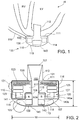
- a left ventricular assist blood pump 100 having a puck-shaped housing 110 is implanted in a patient's body with a first face 111 of the housing 110 positioned against the patient's heart H and a second face 113 of the housing 110 facing away from the heart H.
- the first face 111 of the housing 110 includes an inlet cannula 112 extending into the left ventricle LV of the heart H.
- the second face 113 of the housing 110 has a chamfered edge 114 to avoid irritating other tissue that may come into contact with the blood pump 100, such as the patient's diaphragm.
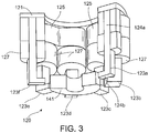
- a stator 120 and electronics 130 of the pump 100 arc positioned on the inflow side of the housing toward first face 111, and a rotor 140 of the pump 100 is positioned along the second face 113.
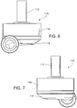
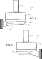
- This positioning of the stator 120, electronics 130, and rotor 140 permits the edge 114 to be chamfered along the contour of the rotor 140, as illustrated in at least Figs. 2 , 4 , and 6-9 , for example.
- the blood pump 100 includes a dividing wall 115 within the housing 110 defining a blood flow conduit 103.
- the blood flow conduit 103 extends from an inlet opening 101 of the inlet cannula 112 through the stator 120 to an outlet opening 105 defined by the housing 110.
- the rotor 140 is positioned within the blood flow conduit 103.
- the stator 120 is disposed circumferentially about a first portion 140a of the rotor 140, for example about a permanent magnet 141.
- the stator 120 is also positioned relative to the rotor 140 such that, in use, blood flows within the blood flow conduit 103 through the stator 120 before reaching the rotor 140.
- the permanent magnet 141 has a permanent magnetic north pole N and a permanent magnetic south pole S for combined active and passive magnetic levitation of the rotor 140 and for rotation of the rotor 140.
- the rotor 140 also has a second portion 140b that includes impeller blades 143.
- the impeller blades 143 are located within a volute 107 of the blood flow conduit such that the impeller blades 143 arc located proximate to the second face 113 of the housing 110.
- the puck-shaped housing 110 further includes a peripheral wall 116 that extends between the first face 111 and a removable cap 118.
- the peripheral wall 116 is formed as a hollow circular cylinder having a width W between opposing portions of the peripheral wall 116.
- the housing 110 also has a thickness T between the first face 111 and the second face 113 that is less than the width W.
- the thickness T is from about 0.5 inches to about 1.5 inches, and the width W is from about 1 inch to about 4 inches.
- the width W can be approximately 2 inches, and the thickness T can be approximately 1 inch.
- the peripheral wall 116 encloses an internal compartment 117 that surrounds the dividing wall 115 and the blood flow conduit 103, with the stator 120 and the electronics 130 disposed in the internal compartment 117 about the dividing wall 115.
- the removable cap 118 includes the second face 113, the chamfered edge 114, and defines the outlet opening 105.
- the cap 118 can be threadably engaged with the peripheral wall 116 to seal the cap 118 in engagement with the peripheral wall 116.
- the cap 118 includes an inner surface 118a of the cap 118 that defines the volute 107 that is in fluid communication with the outlet opening 105.
- the electronics 130 are positioned adjacent to the first face 111 and the stator 120 is positioned adjacent to the electronics 130 on an opposite side of the electronics 130 from the first face 111.
- the electronics 130 include circuit boards 131 and various components 133 carried on the circuit boards 131 to control the operation of the pump 100 by controlling the electrical supply to the stator 120.
- the housing 110 is configured to receive the circuit boards 131 within the internal compartment 117 generally parallel to the first face 111 for efficient use of the space within the internal compartment 117.
- the circuit boards also extend radially-inward towards the dividing wall 115 and radially-outward towards the peripheral wall 116.
- the internal compartment 117 is generally sized no larger than necessary to accommodate the circuit boards 131, and space for heat dissipation, material expansion, potting materials, and/or other elements used in installing the circuit boards 131.
- the external shape of the housing 110 proximate the first face 111 generally fits the shape of the circuits boards 131 closely to provide external dimensions that are not much greater than the dimensions of the circuit boards 131.
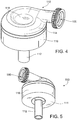
- the stator 120 includes a back iron 121 and pole pieces 123a-123f arranged at intervals around the dividing wall 115.
- the back iron 121 extends around the dividing wall 115 and is formed as a generally flat disc of a ferromagnetic material, such as steel, in order to conduct magnetic flux.
- the back iron 121 is arranged beside the control electronics 130 and provides a base for the pole pieces 123a-123f.
- Each of the pole piece 123a-123f is L-shaped and has a drive coil 125 for generating an electromagnetic field to rotate the rotor 140.
- the pole piece 123a has a first leg 124a that contacts the back iron 121 and extends from the back iron 121 towards the second face 113.
- the pole piece 123a also has a second leg 124b that extends from the first leg 124a towards the dividing wall 115 proximate the location of the permanent magnet 141 of the rotor 140.
- Each of the pole pieces 123a-123f also has a levitation coil 127 for generating an electromagnetic field to control the radial position of the rotor 140.
- Each of the drive coils 125 and the levitation coils 127 includes multiple windings of a conductor around the pole pieces 123a-123f. Particularly, each of the drive coils 125 is wound around two adjacent ones of the pole pieces 123, such as pole pieces 123d and 123e, and each levitation coil 127 is wound around a single pole piece. The drive coils 125 and the levitation coils 127 are wound around the first legs of the pole pieces 123, and magnetic flux generated by passing electrical current though the coils 125 and 127 during use is conducted through the first legs and the second legs of the pole pieces 123 and the back iron 121.
- the drive coils 125 and the levitation coils 127 of the stator 120 are arranged in opposing pairs and are controlled to drive the rotor and to radially levitate the rotor 140 by generating electromagnetic fields that interact with the permanent magnetic poles S and N of the permanent magnet 141. Because the stator 120 includes both the drive coils 125 and the levitation coils 127, only a single stator is needed to levitate the rotor 140 using only passive and active magnetic forces.
- the permanent magnet 141 in this configuration has only one magnetic moment and is formed from a monolithic permanent magnetic body 141.
- the stator 120 can be controlled as discussed in U.S. Patent No. 6,351,048 , the entire contents of which are incorporated herein by reference.
- the control electronics 130 and the stator 120 receive electrical power from a remote power supply via a cable 119 ( Fig. 1 ).
- the rotor 140 is arranged within the housing 110 such that its permanent magnet 141 is located upstream of impeller blades in a location closer to the inlet opening 100.
- the permanent magnet 141 is received within the blood flow conduit 103 proximate the second legs 124b of the pole pieces 123 to provide the passive axial centering force though interaction of the permanent magnet 141 and ferromagnetic material of the pole pieces 123.
- the permanent magnet 141 of the rotor 140 and the dividing wall 115 form a gap 108 between the permanent magnet 141 and the dividing wall 115 when the rotor 140 is centered within the dividing wall 115.
- the gap 108 may be from about 0.2 millimeters to about 2 millimeters. For example, the gap 108 is approximately 1 millimeter.
- the north permanent magnetic pole N and the south permanent magnetic pole S of the permanent magnet 141 provide a permanent magnetic attractive force between the rotor 140 and the stator 120 that acts as a passive axial centering force that tends to maintain the rotor 140 generally centered within the stator 120 and tends to resist the rotor 140 from moving towards the first face 111 or towards the second face 113.
- the gap 108 is smaller, the magnetic attractive force between the permanent magnet 141 and the stator 120 is greater, and the gap 108 is sized to allow the permanent magnet 141 to provide the passive magnetic axial centering force having a magnitude that is adequate to limit the rotor 140 from contacting the dividing wall 115 or the inner surface 118a of the cap 118.
- the rotor 140 also includes a shroud 145 that covers the ends of the impeller blades 143 facing the second face 113 that assists in directing blood flow into the volute 107.
- the shroud 145 and the inner surface 118a of the cap 118 form a gap 109 between the shroud 145 and the inner surface 118a when the rotor 140 is levitated by the stator 120.
- the gap 109 is from about 0.2 millimeters to about 2 millimeters. For example, the gap 109 is approximately 1 millimeter.
- the blood flow conduit 103 As blood flows through the blood flow conduit 103, blood flows through a central aperture 141a formed through the permanent magnet 141. Blood also flows through the gap 108 between the rotor 140 and the dividing wall 115 and through the gap 109 between the shroud 145 and the inner surface 108a of the cap 118.
- the gaps 108 and 109 are large enough to allow adequate blood flow to limit clot formation that may occur if the blood is allowed to become stagnant.
- the gaps 108 and 109 are also large enough to limit pressure forces on the blood cells such that the blood is not damaged when flowing through the pump 100. As a result of the size of the gaps 108 and 109 limiting pressure forces on the blood cells, the gaps 108 and 109 are too large to provide a meaningful hydrodynamic suspension effect. That is to say, the blood does not act as a bearing within the gaps 108 and 109, and the rotor is only magnetically-levitated.
- the rotor 140 is radially suspended by active control of the levitation coils 127 as discussed above, and because the rotor 140 is axially suspended by passive interaction of the permanent magnet 141 and the stator 120, no rotor levitation components are needed proximate the second face 113.
- the incorporation of all the components for rotor levitation in the stator 120 i.e., the levitation coils 127 and the pole pieces 123) allows the cap 118 to be contoured to the shape of the impeller blades 141 and the volute 107. Additionally, incorporation of all the rotor levitation components in the stator 120 eliminates the need for electrical connectors extending from the compartment 117 to the cap 118, which allows the cap to be easily installed and/or removed and eliminates potential sources of pump failure.
- the drive coils 125 of the stator 120 generates electromagnetic fields through the pole pieces 123 that selectively attract and repel the magnetic north pole N and the magnetic south pole S of the rotor 140 to cause the rotor 140 to rotate within stator 120.
- the impeller blades 143 force blood into the volute 107 such that blood is forced out of the outlet opening 105.
- the rotor draws blood into pump 100 through the inlet opening 101.
- the blood flows through the inlet opening 101 and flows through the control electronics 130 and the stator 120 toward the rotor 140.
- the cap 118 can be engaged with the peripheral wall 116 using a different attachment mechanism or technique, including snap-fit engagement, adhesives, or welding.
- the cap 118 has been described as defining the outlet opening 105 and the chamfered edge 114, the outlet opening 105 and/or the chamfered edge 114 can be defined by the peripheral wall 116 or by both the peripheral wall 116 and the cap 118.
- the dividing wall 115 can be formed as part of the cap 118.
- the rotor 140 can include two or more permanent magnets.
- the number and configuration of the pole pieces 123 can also be varied.
- the operation of the control electronics 130 is selected to account for the number and position of pole pieces of the stator and permanent magnets of the rotor.
- the cap 118 can be engaged with the peripheral wall using other techniques, such as adhesives, welding, snap-fit, shrink-fit, or other technique or structure.
- the first face 111 may be formed from a separate piece of material than the peripheral wall 116 and the first face 111, including the inlet cannula 112, can be attached to the peripheral wall 116, such as by welding, after the control electronics 130 and the stator 120 have been mounted in the internal compartment 117.
- the shroud 145 may be omitted and optionally replaced by other flow control devices to achieve a desired pump efficiency.
- the control electronics 130 can be located external to the pump 100, such as in a separate housing implanted in the patient's abdomen, or external to the patient's body.
- the dimensions of the housing 110 can be larger or smaller than those described above.
- the ratio of the width W of the housing 110 to the thickness T of the housing can be different than the ratio described above.
- the width W can be from about 1.1 to about 5 times greater than the thickness T.
- the permanent magnet 141 of the rotor 140 can include two or more pairs of north and south magnetic poles. While the peripheral wall 116 and the dividing wall 115 are illustrated as cylinders having circular cross-sectional shapes, one or both can alternatively be formed having other cross-sectional shapes, such as oval, or an irregular shape. Similarly, the peripheral wall 116 can be tapered such that the housing does not have a constant width W from the first face 111 to the second face 113.
- the blood pump 100 can be used to assist a patient's heart during a transition period, such as during a recovery from illness and/or surgery or other treatment.
- the blood pump 100 can be used to partially or completely replace the function of the patient's heart on a generally permanent basis, such as where the patient's aortic valve is surgically sealed.
Landscapes
- Health & Medical Sciences (AREA)
- Engineering & Computer Science (AREA)
- Heart & Thoracic Surgery (AREA)
- Mechanical Engineering (AREA)
- Cardiology (AREA)
- Hematology (AREA)
- Animal Behavior & Ethology (AREA)
- Veterinary Medicine (AREA)
- Anesthesiology (AREA)
- Biomedical Technology (AREA)
- Public Health (AREA)
- Life Sciences & Earth Sciences (AREA)
- General Health & Medical Sciences (AREA)
- General Engineering & Computer Science (AREA)
- Electromagnetism (AREA)
- Physics & Mathematics (AREA)
- Medical Informatics (AREA)
- Vascular Medicine (AREA)
- External Artificial Organs (AREA)
- Structures Of Non-Positive Displacement Pumps (AREA)
Applications Claiming Priority (3)
| Application Number | Priority Date | Filing Date | Title |
|---|---|---|---|
| US37550410P | 2010-08-20 | 2010-08-20 | |
| EP11750037.1A EP2605809B1 (fr) | 2010-08-20 | 2011-08-18 | Pompe sanguine implantable |
| PCT/US2011/048259 WO2012024493A1 (fr) | 2010-08-20 | 2011-08-18 | Pompe sanguine implantable |
Related Parent Applications (2)
| Application Number | Title | Priority Date | Filing Date |
|---|---|---|---|
| EP11750037.1A Division-Into EP2605809B1 (fr) | 2010-08-20 | 2011-08-18 | Pompe sanguine implantable |
| EP11750037.1A Division EP2605809B1 (fr) | 2010-08-20 | 2011-08-18 | Pompe sanguine implantable |
Publications (2)
| Publication Number | Publication Date |
|---|---|
| EP3248628A1 true EP3248628A1 (fr) | 2017-11-29 |
| EP3248628B1 EP3248628B1 (fr) | 2019-01-02 |
Family
ID=44534700
Family Applications (2)
| Application Number | Title | Priority Date | Filing Date |
|---|---|---|---|
| EP17178651.0A Active EP3248628B1 (fr) | 2010-08-20 | 2011-08-18 | Pompe sanguine implantable |
| EP11750037.1A Active EP2605809B1 (fr) | 2010-08-20 | 2011-08-18 | Pompe sanguine implantable |
Family Applications After (1)
| Application Number | Title | Priority Date | Filing Date |
|---|---|---|---|
| EP11750037.1A Active EP2605809B1 (fr) | 2010-08-20 | 2011-08-18 | Pompe sanguine implantable |
Country Status (7)
| Country | Link |
|---|---|
| US (3) | US9091271B2 (fr) |
| EP (2) | EP3248628B1 (fr) |
| JP (1) | JP5977237B2 (fr) |
| AU (1) | AU2011291984B2 (fr) |
| CA (1) | CA2808658C (fr) |
| TW (1) | TW201212960A (fr) |
| WO (1) | WO2012024493A1 (fr) |
Cited By (13)
| Publication number | Priority date | Publication date | Assignee | Title |
|---|---|---|---|---|
| US10722631B2 (en) | 2018-02-01 | 2020-07-28 | Shifamed Holdings, Llc | Intravascular blood pumps and methods of use and manufacture |
| US11185677B2 (en) | 2017-06-07 | 2021-11-30 | Shifamed Holdings, Llc | Intravascular fluid movement devices, systems, and methods of use |
| US11511103B2 (en) | 2017-11-13 | 2022-11-29 | Shifamed Holdings, Llc | Intravascular fluid movement devices, systems, and methods of use |
| US11654275B2 (en) | 2019-07-22 | 2023-05-23 | Shifamed Holdings, Llc | Intravascular blood pumps with struts and methods of use and manufacture |
| US11724089B2 (en) | 2019-09-25 | 2023-08-15 | Shifamed Holdings, Llc | Intravascular blood pump systems and methods of use and control thereof |
| US11964145B2 (en) | 2019-07-12 | 2024-04-23 | Shifamed Holdings, Llc | Intravascular blood pumps and methods of manufacture and use |
| US12102815B2 (en) | 2019-09-25 | 2024-10-01 | Shifamed Holdings, Llc | Catheter blood pumps and collapsible pump housings |
| US12121713B2 (en) | 2019-09-25 | 2024-10-22 | Shifamed Holdings, Llc | Catheter blood pumps and collapsible blood conduits |
| US12161857B2 (en) | 2018-07-31 | 2024-12-10 | Shifamed Holdings, Llc | Intravascular blood pumps and methods of use |
| US12220570B2 (en) | 2018-10-05 | 2025-02-11 | Shifamed Holdings, Llc | Intravascular blood pumps and methods of use |
| US12409310B2 (en) | 2019-12-11 | 2025-09-09 | Shifamed Holdings, Llc | Descending aorta and vena cava blood pumps |
| US12465748B2 (en) | 2019-08-07 | 2025-11-11 | Supira Medical, Inc. | Catheter blood pumps and collapsible pump housings |
| US12599758B2 (en) | 2019-12-19 | 2026-04-14 | Shifamed Holdings, Llc | Intravascular blood pumps, motors, and fluid control |
Families Citing this family (114)
| Publication number | Priority date | Publication date | Assignee | Title |
|---|---|---|---|---|
| EP3248628B1 (fr) | 2010-08-20 | 2019-01-02 | Tc1 Llc | Pompe sanguine implantable |
| EP2995327A1 (fr) | 2011-03-02 | 2016-03-16 | Thoratec Corporation | Manchon ventriculaire |
| DE102012200806B4 (de) * | 2012-01-20 | 2014-07-31 | Yasa Motors Poland Sp. z.o.o. | Nassläuferpumpe mit Leistungselektronik |
| US9981076B2 (en) | 2012-03-02 | 2018-05-29 | Tc1 Llc | Ventricular cuff |
| US9199019B2 (en) | 2012-08-31 | 2015-12-01 | Thoratec Corporation | Ventricular cuff |
| EP3159023B1 (fr) * | 2012-03-05 | 2017-11-29 | Tc1 Llc | Methode de calibrage de pompes medicales implantables |
| EP2890420B1 (fr) * | 2012-08-31 | 2018-08-29 | Tc1 Llc | Algorithme de détection d'instabilité destiné à une pompe à sang implantable |
| US9492599B2 (en) | 2012-08-31 | 2016-11-15 | Thoratec Corporation | Hall sensor mounting in an implantable blood pump |
| WO2014036410A1 (fr) * | 2012-08-31 | 2014-03-06 | Thoratec Corporation | Algorithme de démarrage destiné à une pompe sanguine implantable |
| US20140188148A1 (en) | 2012-12-27 | 2014-07-03 | Pieter W.C.J. le Blanc | Surgical tunneler |
| DE102013013700A1 (de) * | 2013-04-05 | 2014-10-09 | CircuLite GmbH | Implantierbare Blutpumpe, Blutpumpensystem und Verfahren zur Datenübertragung in einem Blutpumpensystem |
| EP3131600B1 (fr) | 2014-04-15 | 2021-06-16 | Tc1 Llc | Procédés et systèmes pour fournir une rétroaction de batterie à un patient |
| US9744280B2 (en) | 2014-04-15 | 2017-08-29 | Tc1 Llc | Methods for LVAD operation during communication losses |
| US9526818B2 (en) | 2014-04-15 | 2016-12-27 | Thoratec Corporation | Protective cap for driveline cable connector |
| CN110101927B (zh) * | 2014-04-15 | 2021-10-08 | Tc1有限责任公司 | 用于控制血泵的方法和系统 |
| WO2015160995A1 (fr) | 2014-04-15 | 2015-10-22 | Thoratec Corporation | Dispositifs d'assistance ventriculaire |
| EP3131598B1 (fr) | 2014-04-15 | 2020-10-21 | Tc1 Llc | Systèmes de mise à jour de dispositifs d'assistance pour |
| AT515555B1 (de) * | 2014-05-15 | 2015-10-15 | Univ Wien Tech | Magnetkupplung |
| EP2962710A1 (fr) | 2014-07-03 | 2016-01-06 | Berlin Heart GmbH | Procédé et système d'assistance ventriculaire destinés à déterminer une pression d'évacuation |
| WO2016036967A1 (fr) | 2014-09-03 | 2016-03-10 | Thoratec Corporation | Câble de transmission à triple hélice et ses procédés d'assemblage et d'utilisation |
| WO2016187057A1 (fr) | 2015-05-15 | 2016-11-24 | Thoratec Corporation | Amélioration d'une pompe à sang à écoulement axial |
| WO2017015268A1 (fr) | 2015-07-20 | 2017-01-26 | Thoratec Corporation | Estimation de débit à l'aide de capteurs à effet hall |
| WO2017015210A1 (fr) | 2015-07-20 | 2017-01-26 | Thoratec Corporation | Tensiomètre pour l'estimation de débit |
| US10029038B2 (en) | 2015-07-21 | 2018-07-24 | Tc1 Llc | Cantilevered rotor pump and methods for axial flow blood pumping |
| EP3340925B1 (fr) | 2015-08-28 | 2020-09-23 | Tc1 Llc | Dispositifs de commande de pompe à sang et procédés d'utilisation pour un rendement énergétique amélioré |
| WO2017087728A1 (fr) | 2015-11-20 | 2017-05-26 | Tc1 Llc | Connecteurs et câbles améliorés destinés à être utilisés avec des systèmes d'assistance ventriculaire |
| WO2017087785A1 (fr) | 2015-11-20 | 2017-05-26 | Tc1 Llc | Gestion de l'énergie de dispositifs de commande de pompe à sang |
| EP3377133B1 (fr) | 2015-11-20 | 2021-07-14 | Tc1 Llc | Architecture de système permettant un remplacement par un patient de module d'interface/dispositif de commande vad sans détacher un module ancien |
| EP3711788B1 (fr) | 2015-11-20 | 2022-08-03 | Tc1 Llc | Contrôleurs de pompe à sang ayant des batteries disposées en guirlande |
| EP3222301B1 (fr) * | 2016-03-23 | 2018-05-09 | Abiomed Europe GmbH | Pompe sanguine |
| US9985374B2 (en) | 2016-05-06 | 2018-05-29 | Tc1 Llc | Compliant implantable connector and methods of use and manufacture |
| WO2018017716A1 (fr) | 2016-07-21 | 2018-01-25 | Tc1 Llc | Pompe à rotor en porte-à-faux et méthodes de pompe de sang à écoulement axial. |
| WO2018031741A1 (fr) | 2016-08-12 | 2018-02-15 | Tc1 Llc | Dispositifs et procédés de surveillance des performances d'un palier et d'un joint |
| WO2018039124A1 (fr) | 2016-08-22 | 2018-03-01 | Tc1 Llc | Manchon de pompe cardiaque |
| EP3503940B1 (fr) | 2016-08-26 | 2020-11-25 | Tc1 Llc | Prothèse de côte à connecteur percutané intégré pour dispositifs d'assistance ventriculaire. |
| EP3515527A4 (fr) | 2016-09-26 | 2020-05-13 | Tc1 Llc | Modulation de puissance pour pompe cardiaque |
| US10665080B2 (en) | 2016-10-20 | 2020-05-26 | Tc1 Llc | Methods and systems for bone conduction audible alarms for mechanical circulatory support systems |
| US10053230B2 (en) * | 2016-12-26 | 2018-08-21 | Haoxiang Electric Energy (Kunshan) Co., Ltd. | Magnetic levitation obstacle avoidance device and magnetic levitation holder |
| US10894114B2 (en) | 2017-01-12 | 2021-01-19 | Tc1 Llc | Driveline bone anchors and methods of use |
| WO2018132708A1 (fr) | 2017-01-12 | 2018-07-19 | Tc1 Llc | Dispositifs d'ancrage de ligne de transmission percutanée et procédés d'utilisation |
| WO2018136592A2 (fr) | 2017-01-18 | 2018-07-26 | Tc1 Llc | Systèmes et procédés de transfert d'énergie transcutané à l'aide de micro-aiguilles |
| US11235137B2 (en) | 2017-02-24 | 2022-02-01 | Tc1 Llc | Minimally invasive methods and devices for ventricular assist device implantation |
| WO2018183567A1 (fr) | 2017-03-29 | 2018-10-04 | Tc1 Llc | Architecture et procédés de communication pour systèmes de traitement cardiaque |
| WO2018183565A1 (fr) | 2017-03-29 | 2018-10-04 | Harjes Daniel I | Ajustement de protocole sur la base d'un rythme cardiaque irrégulier |
| WO2018183568A1 (fr) | 2017-03-29 | 2018-10-04 | Tc1 Llc | Dispositifs d'assistance ventriculaire à détection de pression et procédés d'utilisation |
| WO2018195301A1 (fr) | 2017-04-21 | 2018-10-25 | Tc1 Llc | Connecteurs aortiques et procédés d'utilisation |
| EP3615104A1 (fr) | 2017-04-28 | 2020-03-04 | Tc1 Llc | Adaptateur de patient pour câble de câble de transmission et méthodes |
| EP4295895A3 (fr) * | 2017-05-11 | 2024-03-27 | Tc1 Llc | Interconnexion thermique pour pompe à sang implantable |
| US11191947B2 (en) | 2018-01-02 | 2021-12-07 | Tc1 Llc | Fluid treatment system for a driveline cable and methods of assembly and use |
| US10973967B2 (en) | 2018-01-10 | 2021-04-13 | Tc1 Llc | Bearingless implantable blood pump |
| US10701043B2 (en) | 2018-01-17 | 2020-06-30 | Tc1 Llc | Methods for physical authentication of medical devices during wireless pairing |
| DE102018201030B4 (de) | 2018-01-24 | 2025-10-16 | Kardion Gmbh | Magnetkuppelelement mit magnetischer Lagerungsfunktion |
| US11529508B2 (en) | 2018-03-02 | 2022-12-20 | Tc1 Llc | Wearable accessory for ventricular assist system |
| WO2019178519A1 (fr) | 2018-03-15 | 2019-09-19 | Tc1 Llc | Procédés et systèmes de prévention de l'insuffisance cardiaque droite |
| US11167123B2 (en) | 2018-03-19 | 2021-11-09 | Tc1 Llc | Coordinated ventricular assist and cardiac rhythm management devices and methods |
| WO2019183126A1 (fr) | 2018-03-20 | 2019-09-26 | Tc1 Llc | Jauge mécanique pour estimer des changements d'inductance dans des systèmes de transfert d'énergie par résonance comportant des bobines souples destinée à être utilisée avec des dispositifs médicaux implantés |
| WO2019182691A1 (fr) | 2018-03-21 | 2019-09-26 | Tc1 Llc | Connecteurs de transmission améliorés et leurs procédés d'utilisation avec des contrôleurs de pompe cardiaque |
| US11389641B2 (en) | 2018-03-21 | 2022-07-19 | Tc1 Llc | Modular flying lead cable and methods for use with heart pump controllers |
| EP3773272B1 (fr) | 2018-03-26 | 2022-09-28 | Tc1 Llc | Systèmes d'irrigation et de capture de particules pendant une implantation de pompe cardiaque |
| RU2683069C1 (ru) * | 2018-03-29 | 2019-03-26 | Федеральное государственное бюджетное учреждение "Национальный медицинский исследовательский центр трансплантологии и искусственных органов имени академика В.И. Шумакова" Министерства здравоохранения Российской Федерации (ФГБУ "НМИЦ ТИО им. ак. В.И. Шумакова" Минздрава России) | Центробежный насос для механической поддержки кровообращения |
| EP4299104B1 (fr) | 2018-04-30 | 2026-03-04 | Tc1 Llc | Raccords de pompe à sang perfectionnés |
| DE102018207575A1 (de) | 2018-05-16 | 2019-11-21 | Kardion Gmbh | Magnetische Stirndreh-Kupplung zur Übertragung von Drehmomenten |
| DE102018207611A1 (de) | 2018-05-16 | 2019-11-21 | Kardion Gmbh | Rotorlagerungssystem |
| DE102018207594A1 (de) | 2018-05-16 | 2019-11-21 | Kardion Gmbh | Rotor, Magnetkupplungsvorrichtung, Elektromotor für ein Herzunterstützungssystem, Pumpeneinheit für ein Herzunterstützungssystem sowie Verfahren zum Herstellen eines Rotors |
| DE102018208538A1 (de) | 2018-05-30 | 2019-12-05 | Kardion Gmbh | Intravasale Blutpumpe und Verfahren zur Herstellung von elektrischen Leiterbahnen |
| DE102018208539A1 (de) | 2018-05-30 | 2019-12-05 | Kardion Gmbh | Motorgehäusemodul zum Abdichten eines Motorraums eines Motors eines Herzunterstützungssystems und Herzunterstützungssystem und Verfahren zum Montieren eines Herzunterstützungssystems |
| DE102018208550A1 (de) | 2018-05-30 | 2019-12-05 | Kardion Gmbh | Leitungsvorrichtung zum Leiten eines Blutstroms für ein Herzunterstützungssystem, Herzunterstützungssystem und Verfahren zum Herstellen einer Leitungsvorrichtung |
| DE102018208549A1 (de) | 2018-05-30 | 2019-12-05 | Kardion Gmbh | Elektronikmodul für ein Herzunterstützungssystem und Verfahren zum Herstellen eines Elektronikmoduls für ein Herzunterstützungssystem |
| DE102018208541A1 (de) | 2018-05-30 | 2019-12-05 | Kardion Gmbh | Axialpumpe für ein Herzunterstützungssystem und Verfahren zum Herstellen einer Axialpumpe für ein Herzunterstützungssystem |
| US11224736B2 (en) | 2018-05-31 | 2022-01-18 | Tc1 Llc | Blood pump controllers |
| DE102018208862A1 (de) | 2018-06-06 | 2019-12-12 | Kardion Gmbh | Implantierbares, vaskuläres Unterstützungssystem |
| DE102018208913A1 (de) | 2018-06-06 | 2019-12-12 | Kardion Gmbh | Verfahren zum Betreiben eines implantierten, ventrikulären Unterstützungssystems |
| DE102018208931A1 (de) | 2018-06-06 | 2019-12-12 | Kardion Gmbh | Vorrichtung zum Bestimmen eines Herzzeitvolumens für ein Herzunterstützungssystem, Herzunterstützungssystem und Verfahren zum Bestimmen eines Herzzeitvolumens |
| DE102018208933A1 (de) | 2018-06-06 | 2019-12-12 | Kardion Gmbh | Verfahren zur Bestimmung einer Strömungsgeschwindigkeit eines durch ein implantiertes, vaskuläres Unterstützungssystem strömenden Fluids |
| DE102018208945A1 (de) | 2018-06-06 | 2019-12-12 | Kardion Gmbh | Analysevorrichtung und Verfahren zum Analysieren einer Viskosität eines Fluids |
| DE102018208879A1 (de) | 2018-06-06 | 2020-01-30 | Kardion Gmbh | Verfahren zur Bestimmung eines Fluid-Gesamtvolumenstroms im Bereich eines implantierten, vaskuläres Unterstützungssystems |
| DE102018208892A1 (de) | 2018-06-06 | 2019-12-12 | Kardion Gmbh | Sensorkopfvorrichtung für ein minimalinvasives Herzunterstützungssystem und Verfahren zum Herstellen einer Sensorkopfvorrichtung für ein Herzunterstützungssystem |
| DE102018208929A1 (de) | 2018-06-06 | 2019-12-12 | Kardion Gmbh | Verfahren zur Bestimmung einer Strömungsgeschwindigkeit eines durch ein implantiertes, vaskuläres Unterstützungssystem strömenden Fluids |
| DE102018208936A1 (de) | 2018-06-06 | 2019-12-12 | Kardion Gmbh | Bestimmvorrichtung und Verfahren zum Bestimmen einer Viskosität eines Fluids |
| DE102018208870A1 (de) | 2018-06-06 | 2019-12-12 | Kardion Gmbh | Verfahren zur Bestimmung eines Fluid-Volumenstroms durch ein implantiertes, vaskuläres Unterstützungssystem |
| DE102018208899A1 (de) | 2018-06-06 | 2019-12-12 | Kardion Gmbh | Verfahren zum Ermitteln der Schallgeschwindigkeit in einem Fluid im Bereich eines implantierten, vaskulären Unterstützungssystems |
| DE102018210076A1 (de) | 2018-06-21 | 2019-12-24 | Kardion Gmbh | Verfahren und Vorrichtung zum Erkennen eines Verschleißzustands eines Herzunterstützungssystems, Verfahren und Vorrichtung zum Betreiben eines Herzunterstützungssystems und Herzunterstützungssystem |
| DE102018210058A1 (de) | 2018-06-21 | 2019-12-24 | Kardion Gmbh | Statorschaufelvorrichtung zur Strömungsführung eines aus einer Austrittsöffnung eines Herzunterstützungssystems ausströmenden Fluids, Herzunterstützungssystem mit Statorschaufelvorrichtung, Verfahren zum Betreiben einer Statorschaufelvorrichtung und Herstellverfahren |
| DE102018211297A1 (de) | 2018-07-09 | 2020-01-09 | Kardion Gmbh | Herzunterstützungssystem und Verfahren zur Überwachung der Integrität einer Haltestruktur eines Herzunterstützungssystems |
| DE102018211328A1 (de) | 2018-07-10 | 2020-01-16 | Kardion Gmbh | Laufradgehäuse für ein implantierbares, vaskuläres Unterstützungssystem |
| DE102018211327A1 (de) | 2018-07-10 | 2020-01-16 | Kardion Gmbh | Laufrad für ein implantierbares, vaskuläres Unterstützungssystem |
| US10947986B2 (en) * | 2018-07-11 | 2021-03-16 | Ch Biomedical (Usa) Inc. | Compact centrifugal pump with magnetically suspended impeller |
| US11241570B2 (en) | 2018-07-17 | 2022-02-08 | Tc1 Llc | Systems and methods for inertial sensing for VAD diagnostics and closed loop control |
| DE102018212153A1 (de) | 2018-07-20 | 2020-01-23 | Kardion Gmbh | Zulaufleitung für eine Pumpeneinheit eines Herzunterstützungssystems, Herzunterstützungssystem und Verfahren zum Herstellen einer Zulaufleitung für eine Pumpeneinheit eines Herzunterstützungssystems |
| AU2019320533B2 (en) | 2018-08-07 | 2024-11-21 | Kardion Gmbh | Bearing device for a cardiac support system, and method for flushing an intermediate space in a bearing device for a cardiac support system |
| DE102018213350A1 (de) | 2018-08-08 | 2020-02-13 | Kardion Gmbh | Vorrichtung und Verfahren zur Überwachung eines Gesundheitszustands des Patienten |
| EP3856274B1 (fr) | 2018-09-25 | 2024-04-17 | Tc1 Llc | Algorithmes de commande de vitesse adaptative et dispositifs de commande d'optimisation de débit dans des dispositifs d'assistance ventriculaire |
| CN118698022A (zh) * | 2018-12-12 | 2024-09-27 | 深圳核心医疗科技股份有限公司 | 心室辅助装置 |
| US12029890B2 (en) | 2020-01-21 | 2024-07-09 | Boston Scientific Scimed, Inc. | Magnetic drives having flux enhancers for blood pumps |
| DE102020102474A1 (de) | 2020-01-31 | 2021-08-05 | Kardion Gmbh | Pumpe zum Fördern eines Fluids und Verfahren zum Herstellen einer Pumpe |
| WO2021257347A1 (fr) | 2020-06-17 | 2021-12-23 | Tc1 Llc | Ensemble pompe à sang extracorporel et ses procédés d'assemblage |
| CA3192451A1 (fr) | 2020-09-14 | 2022-03-17 | Johannes Bette | Pompe de support cardiovasculaire dotee d'un impulseur a zone d'ecoulement variable |
| CN112546425B (zh) * | 2020-10-29 | 2021-07-23 | 苏州心擎医疗技术有限公司 | 磁悬浮马达和磁悬浮血泵 |
| JP2023550938A (ja) | 2020-11-20 | 2023-12-06 | カルディオン ゲーエムベーハー | ガイドワイヤ補助具付き機械的循環支持システム |
| US20220186732A1 (en) * | 2020-12-11 | 2022-06-16 | Sapphire Motors | Integrated pump assembly with one moving part with stacked stator |
| CN112472999B (zh) * | 2020-12-22 | 2025-03-21 | 深圳核心医疗科技股份有限公司 | 血泵 |
| CN117157122A (zh) | 2021-02-10 | 2023-12-01 | 波士顿科学国际有限公司 | 用于血液动力学支持泵的磁性推进器和轴承 |
| US12485271B2 (en) | 2021-04-15 | 2025-12-02 | Tc1 Llc | Systems and methods for medical device connectors |
| JP2022168836A (ja) * | 2021-04-26 | 2022-11-08 | レヴィトロニクス ゲーエムベーハー | 電磁回転駆動装置、遠心ポンプ、及びポンプ・ユニット |
| JP2022168834A (ja) * | 2021-04-26 | 2022-11-08 | レヴィトロニクス ゲーエムベーハー | 電磁回転駆動装置、遠心ポンプ、及びポンプ・ユニット |
| CN118215524A (zh) | 2021-11-16 | 2024-06-18 | 波士顿科学国际有限公司 | 有利于减少溶血的经皮循环支持系统 |
| US12133976B2 (en) | 2021-11-23 | 2024-11-05 | Boston Scientific Scimed, Inc. | Percutaneous circulatory support device facilitating reduced hemolysis class |
| CN116603163B (zh) * | 2022-01-26 | 2024-10-11 | 心擎医疗(苏州)股份有限公司 | 用于对心脏在发生功能衰竭时进行辅助的装置 |
| WO2023158493A1 (fr) | 2022-02-16 | 2023-08-24 | Tc1 Llc | Surveillance de fréquence cardiaque en temps réel pour commande en boucle fermée et/ou synchronisation d'impulsion artificielle de dispositifs d'assistance ventriculaire implantables |
| WO2023229899A1 (fr) | 2022-05-26 | 2023-11-30 | Tc1 Llc | Accéléromètres à trois axes pour surveillance physiologique de patient et commande en boucle fermée de dispositifs d'assistance ventriculaire implantables |
| CN119562841A (zh) | 2022-06-02 | 2025-03-04 | Tc1有限责任公司 | 用于可植入医疗设备的植入连接器增强密封 |
| WO2024050319A1 (fr) | 2022-08-29 | 2024-03-07 | Tc1 Llc | Ensemble connecteur électrique implantable |
| WO2024097236A1 (fr) | 2022-11-01 | 2024-05-10 | Tc1 Llc | Évaluation et gestion de risques d'événements indésirables chez des patients à assistance circulatoire mécanique |
| WO2025137296A1 (fr) | 2023-12-22 | 2025-06-26 | Tc1 Llc | Utilisation d'un capteur de pression ventriculaire gauche pour la mesure de la pression auriculaire gauche et aortique |
Citations (3)
| Publication number | Priority date | Publication date | Assignee | Title |
|---|---|---|---|---|
| US6351048B1 (en) | 1999-06-22 | 2002-02-26 | Levitronix Llc | Electrical rotary drive |
| WO2005032620A1 (fr) * | 2003-10-09 | 2005-04-14 | Ventracor Limited | Turbine |
| US20050135948A1 (en) * | 2003-09-25 | 2005-06-23 | Medforte Research Foundation | Axial-flow blood pump with magnetically suspended, radially and axially stabilized impeller |
Family Cites Families (164)
| Publication number | Priority date | Publication date | Assignee | Title |
|---|---|---|---|---|
| US845816A (en) | 1902-03-05 | 1907-03-05 | Charles H Tompkins | Centripetal-centrifugal pump and condenser. |
| US888654A (en) | 1902-03-05 | 1908-05-26 | Charles H Tompkins | Means for transmitting power. |
| US1026101A (en) | 1910-12-23 | 1912-05-14 | Elon A Marsh | Centrifugal pump. |
| US2128988A (en) | 1937-04-02 | 1938-09-06 | Christian John Russell | Game board |
| US2747512A (en) | 1951-05-24 | 1956-05-29 | Fouche Rene Paul | Motor pump |
| US2864552A (en) | 1954-08-18 | 1958-12-16 | Sir George Godfrey & Partners | Shaft or like bearings |
| CA645624A (en) | 1959-03-20 | 1962-07-24 | A. Buchhold Theodor | Electro-mechanical device |
| US3066849A (en) | 1960-08-18 | 1962-12-04 | Exemplar Inc | High vacuum pump systems |
| US3122101A (en) | 1960-09-22 | 1964-02-25 | North American Aviation Inc | Bearingless pump |
| US3225608A (en) | 1962-11-27 | 1965-12-28 | Gen Motors Corp | Diamagnetic suspension system |
| GB1165884A (en) | 1965-12-03 | 1969-10-01 | Newage Lyon Ltd | Improvements relating to Centrifugal Pumps |
| US3499274A (en) | 1967-08-25 | 1970-03-10 | Rector C Fergason | Cotton harvester |
| US3957389A (en) | 1967-10-26 | 1976-05-18 | Bio-Medicus, Inc. | Pumping apparatus and process characterized by gentle operation |
| DE1933031C3 (de) | 1969-06-30 | 1978-10-26 | Karl 5170 Juelich Boden | Magnetische Lagerung |
| US3575536A (en) | 1969-02-07 | 1971-04-20 | Jet Spray Cooler Inc | Pump for beverage dispenser |
| US3608088A (en) | 1969-04-17 | 1971-09-28 | Univ Minnesota | Implantable blood pump |
| US3597022A (en) | 1969-07-22 | 1971-08-03 | Robert D Waldron | Diamagnetic levitation and/or stabilizing devices |
| US3647324A (en) | 1969-12-18 | 1972-03-07 | Edson Howard Rafferty | Electrically driven pumps capable of use as heart pumps |
| US3611815A (en) | 1969-12-24 | 1971-10-12 | Us Navy | Frictionless gyroscope |
| DE2163256A1 (de) | 1971-12-20 | 1973-07-26 | Maschf Augsburg Nuernberg Ag | Stroemungsmaschine, insbesondere turbopumpe, oder durchstroemmengemesseinrichtung fuer ein aggressives, radioaktives oder reinzuhaltendes stroemungsmittel |
| GB1491710A (en) | 1974-08-15 | 1977-11-16 | Howarth A | Induction machines |
| DE2457783C2 (de) | 1974-12-06 | 1986-10-09 | Arthur Pfeiffer Vakuumtechnik Wetzlar Gmbh, 6334 Asslar | Magnetische Lagerung |
| US4135253A (en) | 1976-11-30 | 1979-01-23 | Medtronic, Inc. | Centrifugal blood pump for cardiac assist |
| US4213207A (en) | 1978-04-07 | 1980-07-22 | Wilson Frederick M | Artificial heart and method of pumping blood |
| FR2451480A1 (fr) | 1979-03-16 | 1980-10-10 | Belenger Jacques | Pompe centrifuge medicale |
| DE2919236C2 (de) | 1979-05-12 | 1982-08-12 | Kernforschungsanlage Jülich GmbH, 5170 Jülich | Magnetisches Schwebelager für einen Rotor |
| DE2938809A1 (de) | 1979-09-25 | 1981-04-02 | Siemens AG, 1000 Berlin und 8000 München | Magnetisches schwebelager |
| JPS5696198A (en) | 1979-12-27 | 1981-08-04 | Matsushita Electric Ind Co Ltd | Pump |
| US4382199A (en) | 1980-11-06 | 1983-05-03 | Nu-Tech Industries, Inc. | Hydrodynamic bearing system for a brushless DC motor |
| DE3280274D1 (de) | 1981-03-18 | 1991-01-31 | Guenther Walter Otto Bramm | Vorrichtung zum pumpen mit einem magnetisch aufgehaengten und angetriebenen rotor. |
| US4688998A (en) | 1981-03-18 | 1987-08-25 | Olsen Don B | Magnetically suspended and rotated impellor pump apparatus and method |
| JPS57181996A (en) | 1981-04-30 | 1982-11-09 | Power Reactor & Nuclear Fuel Dev Corp | Mechanical pump for liquid metal |
| US4405286A (en) | 1982-01-21 | 1983-09-20 | The United States Of America As Represented By The Administrator Of The National Aeronautics And Space Administration | Actively suspended counter-rotating machine |
| US5078741A (en) | 1986-10-12 | 1992-01-07 | Life Extenders Corporation | Magnetically suspended and rotated rotor |
| US4944748A (en) | 1986-10-12 | 1990-07-31 | Bramm Gunter W | Magnetically suspended and rotated rotor |
| US4704121A (en) | 1983-09-28 | 1987-11-03 | Nimbus, Inc. | Anti-thrombogenic blood pump |
| DE3343186A1 (de) | 1983-11-29 | 1985-06-05 | Fraunhofer-Gesellschaft zur Förderung der angewandten Forschung e.V., 8000 München | Magnetische rotorlagerung |
| US4589822A (en) | 1984-07-09 | 1986-05-20 | Mici Limited Partnership Iv | Centrifugal blood pump with impeller |
| US4642036A (en) | 1984-09-17 | 1987-02-10 | Young Niels O | Magnet ball pump |
| FR2613791B1 (fr) | 1987-04-09 | 1992-03-13 | Europ Propulsion | Palier magnetique radial a atterrisseur de secours et application a une turbomachine a suspension magnetique active |
| US4779614A (en) | 1987-04-09 | 1988-10-25 | Nimbus Medical, Inc. | Magnetically suspended rotor axial flow blood pump |
| US4844707A (en) | 1987-06-12 | 1989-07-04 | Kletschka Harold D | Rotary pump |
| US4876492A (en) | 1988-02-26 | 1989-10-24 | General Electric Company | Electronically commutated motor driven apparatus including an impeller in a housing driven by a stator on the housing |
| JPH01257792A (ja) | 1988-04-06 | 1989-10-13 | Fujitsu Ltd | ポンプ装置 |
| JPH0216390A (ja) | 1988-06-30 | 1990-01-19 | Shimadzu Corp | ターボ分子ポンプ |
| JPH0676798B2 (ja) | 1988-08-22 | 1994-09-28 | 株式会社荏原製作所 | 磁気軸受を備えた遠心ポンプ |
| US4878831A (en) | 1988-10-24 | 1989-11-07 | Forney International, Inc. | Infrared flame detector adaptable for different fuels |
| US4957504A (en) | 1988-12-02 | 1990-09-18 | Chardack William M | Implantable blood pump |
| JP2544825B2 (ja) * | 1989-06-05 | 1996-10-16 | 株式会社荏原製作所 | マグネツトポンプ |
| JP3006865B2 (ja) * | 1990-10-11 | 2000-02-07 | エヌティエヌ株式会社 | ターボ形ポンプ |
| US5112202A (en) | 1990-01-31 | 1992-05-12 | Ntn Corporation | Turbo pump with magnetically supported impeller |
| FR2659396B1 (fr) | 1990-03-07 | 1992-05-15 | Cit Alcatel | Pompe a vide pour vide moleculaire propre. |
| US5112200A (en) | 1990-05-29 | 1992-05-12 | Nu-Tech Industries, Inc. | Hydrodynamically suspended rotor axial flow blood pump |
| US5470208A (en) | 1990-10-05 | 1995-11-28 | Kletschka; Harold D. | Fluid pump with magnetically levitated impeller |
| US5055005A (en) | 1990-10-05 | 1991-10-08 | Kletschka Harold D | Fluid pump with levitated impeller |
| US5195877A (en) | 1990-10-05 | 1993-03-23 | Kletschka Harold D | Fluid pump with magnetically levitated impeller |
| US5177387A (en) | 1990-12-04 | 1993-01-05 | University Of Houston-University Park | High temperature superconducting magnetic bearings |
| US5159219A (en) | 1991-05-16 | 1992-10-27 | University Of Houston-University Park | Opposed-magnet bearing with interposed superconductor |
| US5220232A (en) | 1991-09-03 | 1993-06-15 | Allied Signal Aerospace | Stacked magnet superconducting bearing |
| JP2999607B2 (ja) | 1991-09-30 | 2000-01-17 | 日本精工株式会社 | 超電導軸受装置とその操作方法 |
| DE69331271T2 (de) | 1992-07-30 | 2002-12-12 | Cobe Cardiovascular Inc | Kreiselblutpumpe |
| US5527159A (en) | 1993-11-10 | 1996-06-18 | The United States Of America As Represented By The Administrator Of The National Aeronautics And Space Administration | Rotary blood pump |
| US5708346A (en) | 1994-01-10 | 1998-01-13 | Sulzer Electronics Ag | Method and control apparatus for controlling an AC-machine |
| US6808482B1 (en) | 1994-04-15 | 2004-10-26 | Allegheny-Singer Research Institute | Blood pump device and method of producing |
| WO1996017180A1 (fr) | 1994-12-02 | 1996-06-06 | Sulzer Electronics Ag | Procede de compensation de forces vibratoires periodiques dans un generateur a induction electrique |
| EP0819330B1 (fr) | 1995-04-03 | 2001-06-06 | Levitronix LLC | Machine rotative avec systeme electromagnetique d'entrainement en rotation |
| US5725357A (en) | 1995-04-03 | 1998-03-10 | Ntn Corporation | Magnetically suspended type pump |
| EP0845083B1 (fr) | 1995-08-18 | 2004-02-18 | LUST ANTRIEBSTECHNIK GmbH | Palier magnetique et son procede de fonctionnement |
| US5947703A (en) | 1996-01-31 | 1999-09-07 | Ntn Corporation | Centrifugal blood pump assembly |
| JP3553255B2 (ja) | 1996-01-31 | 2004-08-11 | Ntn株式会社 | 粘度計測機能付磁気浮上型ポンプ |
| US5840070A (en) | 1996-02-20 | 1998-11-24 | Kriton Medical, Inc. | Sealless rotary blood pump |
| BR9709305A (pt) * | 1996-05-03 | 1999-08-10 | Univ Utah | Processoãe aparelho de bombeamento contrífugo eletromagneticamente suspenso e girado |
| US6394769B1 (en) | 1996-05-03 | 2002-05-28 | Medquest Products, Inc. | Pump having a magnetically suspended rotor with one active control axis |
| US6302661B1 (en) * | 1996-05-03 | 2001-10-16 | Pratap S. Khanwilkar | Electromagnetically suspended and rotated centrifugal pumping apparatus and method |
| US6244835B1 (en) * | 1996-06-26 | 2001-06-12 | James F. Antaki | Blood pump having a magnetically suspended rotor |
| DE59706479D1 (de) | 1996-07-25 | 2002-04-04 | Lust Antriebstechnik Gmbh | Anordnung und Verfahren zum Betreiben einer magnetgelagerten, elektromotorischen Antriebsvorrichtung bei einer Netzstörung |
| JP4390856B2 (ja) | 1996-09-10 | 2009-12-24 | レビトロニクス エルエルシー | ロータリー・ポンプ及びその駆動方法 |
| AUPO902797A0 (en) | 1997-09-05 | 1997-10-02 | Cortronix Pty Ltd | A rotary blood pump with hydrodynamically suspended impeller |
| DE59712591D1 (de) | 1997-08-25 | 2006-05-04 | Levitronix Llc | Magnetgelagerte Rotationsanordnung |
| EP1019117B2 (fr) | 1997-10-02 | 2015-03-18 | Micromed Technology, Inc. | Unité de contrôle pour système de pompage implantable |
| US6293901B1 (en) | 1997-11-26 | 2001-09-25 | Vascor, Inc. | Magnetically suspended fluid pump and control system |
| US5928131A (en) | 1997-11-26 | 1999-07-27 | Vascor, Inc. | Magnetically suspended fluid pump and control system |
| CA2330048C (fr) * | 1998-04-22 | 2004-04-20 | University Of Utah | Pompe a sang centrifuge a roulements magnetiques hybrides |
| EP0967475B1 (fr) | 1998-06-22 | 2007-11-28 | Levitronix LLC | Méthode pour la détermination de la viscosité d' un liquide |
| DE59915262D1 (de) | 1998-07-10 | 2011-06-01 | Levitronix Llc | Verfahren zur Bestimmung des Druckverlustes und des Durchflusses durch eine Pumpe |
| DE59914570D1 (de) | 1998-08-24 | 2008-01-17 | Levitronix Llc | Sensoranordnung in einem elektromagnetischen Drehantrieb |
| DE59915016D1 (de) | 1998-08-24 | 2009-06-18 | Levitronix Llc | Verfahren zum Bestimmen der radialen Position eines permanentmagnetischen Rotors und elektromagnetischer Drehantrieb |
| EP0989656B1 (fr) | 1998-09-24 | 2009-03-11 | Levitronix LLC | Entraînement de rotation à excitation par aimants permanents |
| DE29821565U1 (de) | 1998-12-02 | 2000-06-15 | Impella Cardiotechnik AG, 52074 Aachen | Lagerlose Blutpumpe |
| US6264635B1 (en) | 1998-12-03 | 2001-07-24 | Kriton Medical, Inc. | Active magnetic bearing system for blood pump |
| AUPP995999A0 (en) | 1999-04-23 | 1999-05-20 | University Of Technology, Sydney | Non-contact estimation and control system |
| US6234772B1 (en) | 1999-04-28 | 2001-05-22 | Kriton Medical, Inc. | Rotary blood pump |
| US6146325A (en) | 1999-06-03 | 2000-11-14 | Arrow International, Inc. | Ventricular assist device |
| US7138776B1 (en) | 1999-07-08 | 2006-11-21 | Heartware, Inc. | Method and apparatus for controlling brushless DC motors in implantable medical devices |
| EP1113177B1 (fr) | 1999-12-27 | 2003-12-03 | Ntn Corporation | Pompe à lévitation magnétique |
| ATE283077T1 (de) | 2000-03-27 | 2004-12-15 | Cleveland Clinic Foundation | Chronisches leistungssteuerungssystem für rotodynamische blutpumpe |
| US6559567B2 (en) | 2000-05-12 | 2003-05-06 | Levitronix Llc | Electromagnetic rotary drive |
| JP2001336528A (ja) | 2000-05-25 | 2001-12-07 | Ntn Corp | 磁気浮上装置 |
| US6589030B2 (en) | 2000-06-20 | 2003-07-08 | Ntn Corporation | Magnetically levitated pump apparatus |
| US6808508B1 (en) | 2000-09-13 | 2004-10-26 | Cardiacassist, Inc. | Method and system for closed chest blood flow support |
| US6626644B2 (en) | 2000-10-30 | 2003-09-30 | Ntn Corporation | Magnetically levitated pump and controlling circuit |
| US6707200B2 (en) | 2000-11-14 | 2004-03-16 | Airex Corporation | Integrated magnetic bearing |
| US6761532B2 (en) * | 2001-03-14 | 2004-07-13 | Vascor, Inc. | Touch down of blood pump impellers |
| DE10123138B4 (de) | 2001-04-30 | 2007-09-27 | Berlin Heart Ag | Verfahren zur Lageregelung eines permanentmagnetisch gelagerten rotierenden Bauteils |
| DE10123139B4 (de) | 2001-04-30 | 2005-08-11 | Berlin Heart Ag | Verfahren zur Regelung einer Unterstützungspumpe für Fluidfördersysteme mit pulsatilem Druck |
| JP3834610B2 (ja) | 2001-07-12 | 2006-10-18 | 独立行政法人産業技術総合研究所 | 動圧軸受を備えた人工心臓ポンプ |
| US6640617B2 (en) | 2001-08-16 | 2003-11-04 | Levitronix Llc | Apparatus and a method for determining the viscosity of a fluid |
| JP2003093500A (ja) * | 2001-09-27 | 2003-04-02 | Nikkiso Co Ltd | 血液ポンプ |
| US6641378B2 (en) | 2001-11-13 | 2003-11-04 | William D. Davis | Pump with electrodynamically supported impeller |
| US7396327B2 (en) | 2002-01-07 | 2008-07-08 | Micromed Technology, Inc. | Blood pump system and method of operation |
| US6901212B2 (en) | 2002-06-13 | 2005-05-31 | Halliburton Energy Services, Inc. | Digital adaptive sensorless commutational drive controller for a brushless DC motor |
| US7338521B2 (en) | 2002-06-13 | 2008-03-04 | World Heart, Inc. | Low profile inlet for an implantable blood pump |
| US6949066B2 (en) | 2002-08-21 | 2005-09-27 | World Heart Corporation | Rotary blood pump diagnostics and cardiac output controller |
| US6817836B2 (en) | 2002-09-10 | 2004-11-16 | Miwatec Incorporated | Methods and apparatus for controlling a continuous flow rotary blood pump |
| US7284956B2 (en) | 2002-09-10 | 2007-10-23 | Miwatec Co., Ltd. | Methods and apparatus for controlling a continuous flow rotary blood pump |
| US7511443B2 (en) | 2002-09-26 | 2009-03-31 | Barrett Technology, Inc. | Ultra-compact, high-performance motor controller and method of using same |
| JP4041376B2 (ja) | 2002-09-30 | 2008-01-30 | テルモ株式会社 | 血液ポンプ装置 |
| DE10330434A1 (de) | 2003-07-04 | 2005-02-03 | Jostra Ag | Zentrifugal-Pumpe |
| US7229258B2 (en) | 2003-09-25 | 2007-06-12 | Medforte Research Foundation | Streamlined unobstructed one-pass axial-flow pump |
| JP2007518464A (ja) | 2003-10-03 | 2007-07-12 | フォスター−ミラー・インコーポレイテッド | 電磁石lcrベアリング付きロータリーポンプ |
| JP4521547B2 (ja) | 2004-04-15 | 2010-08-11 | 株式会社サンメディカル技術研究所 | 血液ポンプの流量推定装置 |
| US7591777B2 (en) | 2004-05-25 | 2009-09-22 | Heartware Inc. | Sensorless flow estimation for implanted ventricle assist device |
| CN101048186A (zh) | 2004-09-07 | 2007-10-03 | 心血管微创医疗公司 | 用于血液泵的生理的控制的方法和系统 |
| US8419609B2 (en) * | 2005-10-05 | 2013-04-16 | Heartware Inc. | Impeller for a rotary ventricular assist device |
| USD534548S1 (en) | 2005-05-26 | 2007-01-02 | Matsushita Electric Industrial Co., Ltd. | Pump |
| EP1898971B1 (fr) | 2005-06-06 | 2015-03-11 | The Cleveland Clinic Foundation | Pompe sanguine |
| JP4517076B2 (ja) * | 2005-06-23 | 2010-08-04 | 独立行政法人産業技術総合研究所 | 動圧軸受を備えた人工心臓ポンプ |
| US8672611B2 (en) | 2006-01-13 | 2014-03-18 | Heartware, Inc. | Stabilizing drive for contactless rotary blood pump impeller |
| EP3954901A1 (fr) | 2006-01-13 | 2022-02-16 | HeartWare, Inc. | Pompe sanguine rotative |
| EP1981585B1 (fr) | 2006-01-27 | 2019-03-06 | CircuLite, Inc. | Systeme d'assistance cardiaque |
| US7850594B2 (en) | 2006-05-09 | 2010-12-14 | Thoratec Corporation | Pulsatile control system for a rotary blood pump |
| RU2009140665A (ru) | 2007-04-05 | 2011-05-10 | Микромед Текнолоджи, Инк. (Us) | Система нагнетания крови и способ ее эксплуатации |
| US8152493B2 (en) | 2007-04-30 | 2012-04-10 | Hearthware Inc. | Centrifugal rotary blood pump with impeller having a hydrodynamic thrust bearing surface |
| JP5415411B2 (ja) | 2007-06-06 | 2014-02-12 | ワールドハート コーポレイション | 交換可能な経皮ケーブルを備える埋め込み型vad |
| AU2008261920A1 (en) | 2007-06-06 | 2008-12-18 | Worldheart Corporation | Wearable VAD controller with reserve battery |
| EP2037236A3 (fr) | 2007-09-11 | 2011-01-19 | Levitronix LLC | Procédé de calibration d'une mesure de débit dans un système d'écoulement et système d'écoulement pour la mise en ouvre de ce procédé |
| EP2282789B1 (fr) | 2008-03-26 | 2015-09-09 | Heart Biotech Limited | Dispositif d'assistance cardiaque |
| EP2274819B1 (fr) | 2008-04-30 | 2017-04-05 | Levitronix GmbH | Machine tournante, procédé pour déterminer un basculement de rotor d'une machine tournante et installation de traitement |
| EP2315609B1 (fr) * | 2008-08-08 | 2015-12-02 | Calon Cardio Technology Ltd | Appareil d'assistance cardiaque |
| JP5103331B2 (ja) | 2008-09-01 | 2012-12-19 | 川崎重工業株式会社 | 舶用スラスタ装置 |
| JP5571087B2 (ja) * | 2008-09-26 | 2014-08-13 | ワールドハート インコーポレーテッド | 磁気浮上血液ポンプ及び該ポンプの小型化を可能にする最適化方法 |
| JP4996578B2 (ja) | 2008-10-28 | 2012-08-08 | 株式会社サンメディカル技術研究所 | 多孔性構造体を具備する医療用装置又は器具 |
| US8517699B2 (en) | 2008-12-16 | 2013-08-27 | Cleveland Clinic Foundation | Centrifugal pump with offset volute |
| US8632449B2 (en) * | 2009-04-16 | 2014-01-21 | Bivacor Pty Ltd | Heart pump controller |
| US9583991B2 (en) | 2009-06-24 | 2017-02-28 | Synchrony, Inc. | Systems, devices, and/or methods for managing magnetic bearings |
| EP2273124B1 (fr) | 2009-07-06 | 2015-02-25 | Levitronix GmbH | Pompe centrifuge et procédé d'équilibrage de la poussée axiale dans une pompe centrifuge |
| EP2319552B1 (fr) | 2009-11-06 | 2014-01-08 | Berlin Heart GmbH | Pompe à sang |
| EP2357374B1 (fr) | 2010-01-29 | 2016-02-17 | Levitronix GmbH | Dispositif de palier magnétique |
| WO2012019126A1 (fr) | 2010-08-06 | 2012-02-09 | Heartware, Inc. | Dispositif de conduit destiné à être utilisé avec un dispositif d'assistance ventriculaire |
| EP3248628B1 (fr) | 2010-08-20 | 2019-01-02 | Tc1 Llc | Pompe sanguine implantable |
| KR101781010B1 (ko) | 2010-09-01 | 2017-10-23 | 레비트로닉스 게엠베하 | 회전 펌프 |
| WO2012054490A1 (fr) | 2010-10-18 | 2012-04-26 | World Heart Corporation | Pompe à sang à pales de roue de séparation et des aubes fixes de séparation et procédés de fabrication |
| US8556795B2 (en) | 2010-11-23 | 2013-10-15 | Minnetronix Inc. | Portable controller with integral power source for mechanical circulation support systems |
| EP2648775B1 (fr) | 2010-12-09 | 2016-03-09 | Heartware, Inc. | Unité de commande et source d'énergie pour pompe à sang implantable |
| US9492601B2 (en) | 2011-01-21 | 2016-11-15 | Heartware, Inc. | Suction detection on an axial blood pump using BEMF data |
| AU2012207146B2 (en) | 2011-01-21 | 2016-10-06 | Heartware, Inc. | Flow estimation in a blood pump |
| US8535212B2 (en) | 2011-03-30 | 2013-09-17 | Jarvik Robert | Centrifugal blood pumps with reverse flow washout |
| WO2013009881A2 (fr) | 2011-07-11 | 2013-01-17 | Vascor, Inc. | Transmission et communication de puissance par voie transcutanée pour un dispositif d'assistance cardiaque implanté et autres dispositifs |
| GB2517609B (en) | 2012-06-08 | 2017-05-31 | Cameron Int Corp | Artificial heart system |
| US9364596B2 (en) | 2013-01-04 | 2016-06-14 | HeartWave, Inc. | Controller and power source for implantable blood pump |
| US8882477B2 (en) | 2013-03-14 | 2014-11-11 | Circulite, Inc. | Magnetically levitated and driven blood pump and method for using the same |
| DE102013013700A1 (de) | 2013-04-05 | 2014-10-09 | CircuLite GmbH | Implantierbare Blutpumpe, Blutpumpensystem und Verfahren zur Datenübertragung in einem Blutpumpensystem |
| US9427508B2 (en) | 2013-06-04 | 2016-08-30 | Heartware, Inc. | Axial flow pump pressure algorithm |
| WO2015023850A1 (fr) | 2013-08-14 | 2015-02-19 | Heartware, Inc. | Hélice pour pompe à flux axial |
-
2011
- 2011-08-18 EP EP17178651.0A patent/EP3248628B1/fr active Active
- 2011-08-18 JP JP2013524979A patent/JP5977237B2/ja not_active Expired - Fee Related
- 2011-08-18 AU AU2011291984A patent/AU2011291984B2/en not_active Ceased
- 2011-08-18 US US13/212,813 patent/US9091271B2/en active Active
- 2011-08-18 CA CA2808658A patent/CA2808658C/fr not_active Expired - Fee Related
- 2011-08-18 WO PCT/US2011/048259 patent/WO2012024493A1/fr not_active Ceased
- 2011-08-18 EP EP11750037.1A patent/EP2605809B1/fr active Active
- 2011-08-19 TW TW100129901A patent/TW201212960A/zh unknown
-
2015
- 2015-06-10 US US14/735,990 patent/US9675741B2/en active Active
-
2017
- 2017-05-12 US US15/594,373 patent/US10500321B2/en active Active
Patent Citations (3)
| Publication number | Priority date | Publication date | Assignee | Title |
|---|---|---|---|---|
| US6351048B1 (en) | 1999-06-22 | 2002-02-26 | Levitronix Llc | Electrical rotary drive |
| US20050135948A1 (en) * | 2003-09-25 | 2005-06-23 | Medforte Research Foundation | Axial-flow blood pump with magnetically suspended, radially and axially stabilized impeller |
| WO2005032620A1 (fr) * | 2003-10-09 | 2005-04-14 | Ventracor Limited | Turbine |
Cited By (16)
| Publication number | Priority date | Publication date | Assignee | Title |
|---|---|---|---|---|
| US11185677B2 (en) | 2017-06-07 | 2021-11-30 | Shifamed Holdings, Llc | Intravascular fluid movement devices, systems, and methods of use |
| US11717670B2 (en) | 2017-06-07 | 2023-08-08 | Shifamed Holdings, LLP | Intravascular fluid movement devices, systems, and methods of use |
| US11511103B2 (en) | 2017-11-13 | 2022-11-29 | Shifamed Holdings, Llc | Intravascular fluid movement devices, systems, and methods of use |
| US12076545B2 (en) | 2018-02-01 | 2024-09-03 | Shifamed Holdings, Llc | Intravascular blood pumps and methods of use and manufacture |
| US11229784B2 (en) | 2018-02-01 | 2022-01-25 | Shifamed Holdings, Llc | Intravascular blood pumps and methods of use and manufacture |
| US10722631B2 (en) | 2018-02-01 | 2020-07-28 | Shifamed Holdings, Llc | Intravascular blood pumps and methods of use and manufacture |
| US12161857B2 (en) | 2018-07-31 | 2024-12-10 | Shifamed Holdings, Llc | Intravascular blood pumps and methods of use |
| US12220570B2 (en) | 2018-10-05 | 2025-02-11 | Shifamed Holdings, Llc | Intravascular blood pumps and methods of use |
| US11964145B2 (en) | 2019-07-12 | 2024-04-23 | Shifamed Holdings, Llc | Intravascular blood pumps and methods of manufacture and use |
| US11654275B2 (en) | 2019-07-22 | 2023-05-23 | Shifamed Holdings, Llc | Intravascular blood pumps with struts and methods of use and manufacture |
| US12465748B2 (en) | 2019-08-07 | 2025-11-11 | Supira Medical, Inc. | Catheter blood pumps and collapsible pump housings |
| US12102815B2 (en) | 2019-09-25 | 2024-10-01 | Shifamed Holdings, Llc | Catheter blood pumps and collapsible pump housings |
| US12121713B2 (en) | 2019-09-25 | 2024-10-22 | Shifamed Holdings, Llc | Catheter blood pumps and collapsible blood conduits |
| US11724089B2 (en) | 2019-09-25 | 2023-08-15 | Shifamed Holdings, Llc | Intravascular blood pump systems and methods of use and control thereof |
| US12409310B2 (en) | 2019-12-11 | 2025-09-09 | Shifamed Holdings, Llc | Descending aorta and vena cava blood pumps |
| US12599758B2 (en) | 2019-12-19 | 2026-04-14 | Shifamed Holdings, Llc | Intravascular blood pumps, motors, and fluid control |
Also Published As
| Publication number | Publication date |
|---|---|
| EP2605809B1 (fr) | 2017-10-11 |
| AU2011291984A1 (en) | 2013-03-14 |
| US20150273125A1 (en) | 2015-10-01 |
| US20120046514A1 (en) | 2012-02-23 |
| CA2808658A1 (fr) | 2012-02-23 |
| US10500321B2 (en) | 2019-12-10 |
| US20170246365A1 (en) | 2017-08-31 |
| EP3248628B1 (fr) | 2019-01-02 |
| JP2013536021A (ja) | 2013-09-19 |
| US9091271B2 (en) | 2015-07-28 |
| US9675741B2 (en) | 2017-06-13 |
| WO2012024493A1 (fr) | 2012-02-23 |
| CA2808658C (fr) | 2017-02-28 |
| AU2011291984B2 (en) | 2014-08-28 |
| TW201212960A (en) | 2012-04-01 |
| JP5977237B2 (ja) | 2016-08-24 |
| EP2605809A1 (fr) | 2013-06-26 |
Similar Documents
| Publication | Publication Date | Title |
|---|---|---|
| AU2011291984B2 (en) | Implantable blood pump | |
| US12383725B2 (en) | Bearingless implantable blood pump | |
| US12017054B2 (en) | Thermal interconnect for implantable blood pump | |
| US10702641B2 (en) | Ventricular assist devices having a hollow rotor and methods of use | |
| US10413650B2 (en) | Hall sensor mounting in an implantable blood pump | |
| JP5539441B2 (ja) | 回転式血液ポンプ | |
| WO2008136979A1 (fr) | Pompe à sang rotative centrifuge |
Legal Events
| Date | Code | Title | Description |
|---|---|---|---|
| PUAI | Public reference made under article 153(3) epc to a published international application that has entered the european phase |
Free format text: ORIGINAL CODE: 0009012 |
|
| STAA | Information on the status of an ep patent application or granted ep patent |
Free format text: STATUS: REQUEST FOR EXAMINATION WAS MADE |
|
| STAA | Information on the status of an ep patent application or granted ep patent |
Free format text: STATUS: EXAMINATION IS IN PROGRESS |
|
| 17P | Request for examination filed |
Effective date: 20170629 |
|
| AC | Divisional application: reference to earlier application |
Ref document number: 2605809 Country of ref document: EP Kind code of ref document: P |
|
| AK | Designated contracting states |
Kind code of ref document: A1 Designated state(s): AL AT BE BG CH CY CZ DE DK EE ES FI FR GB GR HR HU IE IS IT LI LT LU LV MC MK MT NL NO PL PT RO RS SE SI SK SM TR |
|
| 17Q | First examination report despatched |
Effective date: 20171117 |
|
| GRAP | Despatch of communication of intention to grant a patent |
Free format text: ORIGINAL CODE: EPIDOSNIGR1 |
|
| STAA | Information on the status of an ep patent application or granted ep patent |
Free format text: STATUS: GRANT OF PATENT IS INTENDED |
|
| RIC1 | Information provided on ipc code assigned before grant |
Ipc: A61M 1/10 20060101AFI20180612BHEP Ipc: F04D 29/048 20060101ALI20180612BHEP |
|
| INTG | Intention to grant announced |
Effective date: 20180713 |
|
| GRAS | Grant fee paid |
Free format text: ORIGINAL CODE: EPIDOSNIGR3 |
|
| GRAJ | Information related to disapproval of communication of intention to grant by the applicant or resumption of examination proceedings by the epo deleted |
Free format text: ORIGINAL CODE: EPIDOSDIGR1 |
|
| GRAL | Information related to payment of fee for publishing/printing deleted |
Free format text: ORIGINAL CODE: EPIDOSDIGR3 |
|
| GRAJ | Information related to disapproval of communication of intention to grant by the applicant or resumption of examination proceedings by the epo deleted |
Free format text: ORIGINAL CODE: EPIDOSDIGR1 |
|
| GRAL | Information related to payment of fee for publishing/printing deleted |
Free format text: ORIGINAL CODE: EPIDOSDIGR3 |
|
| STAA | Information on the status of an ep patent application or granted ep patent |
Free format text: STATUS: EXAMINATION IS IN PROGRESS |
|
| GRAR | Information related to intention to grant a patent recorded |
Free format text: ORIGINAL CODE: EPIDOSNIGR71 |
|
| STAA | Information on the status of an ep patent application or granted ep patent |
Free format text: STATUS: GRANT OF PATENT IS INTENDED |
|
| GRAA | (expected) grant |
Free format text: ORIGINAL CODE: 0009210 |
|
| STAA | Information on the status of an ep patent application or granted ep patent |
Free format text: STATUS: THE PATENT HAS BEEN GRANTED |
|
| INTG | Intention to grant announced |
Effective date: 20180713 |
|
| INTC | Intention to grant announced (deleted) | ||
| INTG | Intention to grant announced |
Effective date: 20181121 |
|
| AC | Divisional application: reference to earlier application |
Ref document number: 2605809 Country of ref document: EP Kind code of ref document: P |
|
| AK | Designated contracting states |
Kind code of ref document: B1 Designated state(s): AL AT BE BG CH CY CZ DE DK EE ES FI FR GB GR HR HU IE IS IT LI LT LU LV MC MK MT NL NO PL PT RO RS SE SI SK SM TR |
|
| REG | Reference to a national code |
Ref country code: GB Ref legal event code: FG4D |
|
| REG | Reference to a national code |
Ref country code: CH Ref legal event code: EP Ref country code: AT Ref legal event code: REF Ref document number: 1083568 Country of ref document: AT Kind code of ref document: T Effective date: 20190115 |
|
| REG | Reference to a national code |
Ref country code: DE Ref legal event code: R096 Ref document number: 602011055491 Country of ref document: DE |
|
| REG | Reference to a national code |
Ref country code: IE Ref legal event code: FG4D |
|
| REG | Reference to a national code |
Ref country code: NL Ref legal event code: MP Effective date: 20190102 |
|
| REG | Reference to a national code |
Ref country code: LT Ref legal event code: MG4D |
|
| REG | Reference to a national code |
Ref country code: AT Ref legal event code: MK05 Ref document number: 1083568 Country of ref document: AT Kind code of ref document: T Effective date: 20190102 |
|
| PG25 | Lapsed in a contracting state [announced via postgrant information from national office to epo] |
Ref country code: NL Free format text: LAPSE BECAUSE OF FAILURE TO SUBMIT A TRANSLATION OF THE DESCRIPTION OR TO PAY THE FEE WITHIN THE PRESCRIBED TIME-LIMIT Effective date: 20190102 |
|
| PG25 | Lapsed in a contracting state [announced via postgrant information from national office to epo] |
Ref country code: FI Free format text: LAPSE BECAUSE OF FAILURE TO SUBMIT A TRANSLATION OF THE DESCRIPTION OR TO PAY THE FEE WITHIN THE PRESCRIBED TIME-LIMIT Effective date: 20190102 Ref country code: NO Free format text: LAPSE BECAUSE OF FAILURE TO SUBMIT A TRANSLATION OF THE DESCRIPTION OR TO PAY THE FEE WITHIN THE PRESCRIBED TIME-LIMIT Effective date: 20190402 Ref country code: LT Free format text: LAPSE BECAUSE OF FAILURE TO SUBMIT A TRANSLATION OF THE DESCRIPTION OR TO PAY THE FEE WITHIN THE PRESCRIBED TIME-LIMIT Effective date: 20190102 Ref country code: ES Free format text: LAPSE BECAUSE OF FAILURE TO SUBMIT A TRANSLATION OF THE DESCRIPTION OR TO PAY THE FEE WITHIN THE PRESCRIBED TIME-LIMIT Effective date: 20190102 Ref country code: PT Free format text: LAPSE BECAUSE OF FAILURE TO SUBMIT A TRANSLATION OF THE DESCRIPTION OR TO PAY THE FEE WITHIN THE PRESCRIBED TIME-LIMIT Effective date: 20190502 Ref country code: SE Free format text: LAPSE BECAUSE OF FAILURE TO SUBMIT A TRANSLATION OF THE DESCRIPTION OR TO PAY THE FEE WITHIN THE PRESCRIBED TIME-LIMIT Effective date: 20190102 Ref country code: PL Free format text: LAPSE BECAUSE OF FAILURE TO SUBMIT A TRANSLATION OF THE DESCRIPTION OR TO PAY THE FEE WITHIN THE PRESCRIBED TIME-LIMIT Effective date: 20190102 |
|
| PG25 | Lapsed in a contracting state [announced via postgrant information from national office to epo] |
Ref country code: LV Free format text: LAPSE BECAUSE OF FAILURE TO SUBMIT A TRANSLATION OF THE DESCRIPTION OR TO PAY THE FEE WITHIN THE PRESCRIBED TIME-LIMIT Effective date: 20190102 Ref country code: RS Free format text: LAPSE BECAUSE OF FAILURE TO SUBMIT A TRANSLATION OF THE DESCRIPTION OR TO PAY THE FEE WITHIN THE PRESCRIBED TIME-LIMIT Effective date: 20190102 Ref country code: GR Free format text: LAPSE BECAUSE OF FAILURE TO SUBMIT A TRANSLATION OF THE DESCRIPTION OR TO PAY THE FEE WITHIN THE PRESCRIBED TIME-LIMIT Effective date: 20190403 Ref country code: HR Free format text: LAPSE BECAUSE OF FAILURE TO SUBMIT A TRANSLATION OF THE DESCRIPTION OR TO PAY THE FEE WITHIN THE PRESCRIBED TIME-LIMIT Effective date: 20190102 Ref country code: BG Free format text: LAPSE BECAUSE OF FAILURE TO SUBMIT A TRANSLATION OF THE DESCRIPTION OR TO PAY THE FEE WITHIN THE PRESCRIBED TIME-LIMIT Effective date: 20190402 Ref country code: IS Free format text: LAPSE BECAUSE OF FAILURE TO SUBMIT A TRANSLATION OF THE DESCRIPTION OR TO PAY THE FEE WITHIN THE PRESCRIBED TIME-LIMIT Effective date: 20190502 |
|
| REG | Reference to a national code |
Ref country code: DE Ref legal event code: R097 Ref document number: 602011055491 Country of ref document: DE |
|
| PG25 | Lapsed in a contracting state [announced via postgrant information from national office to epo] |
Ref country code: AT Free format text: LAPSE BECAUSE OF FAILURE TO SUBMIT A TRANSLATION OF THE DESCRIPTION OR TO PAY THE FEE WITHIN THE PRESCRIBED TIME-LIMIT Effective date: 20190102 Ref country code: DK Free format text: LAPSE BECAUSE OF FAILURE TO SUBMIT A TRANSLATION OF THE DESCRIPTION OR TO PAY THE FEE WITHIN THE PRESCRIBED TIME-LIMIT Effective date: 20190102 Ref country code: EE Free format text: LAPSE BECAUSE OF FAILURE TO SUBMIT A TRANSLATION OF THE DESCRIPTION OR TO PAY THE FEE WITHIN THE PRESCRIBED TIME-LIMIT Effective date: 20190102 Ref country code: CZ Free format text: LAPSE BECAUSE OF FAILURE TO SUBMIT A TRANSLATION OF THE DESCRIPTION OR TO PAY THE FEE WITHIN THE PRESCRIBED TIME-LIMIT Effective date: 20190102 Ref country code: IT Free format text: LAPSE BECAUSE OF FAILURE TO SUBMIT A TRANSLATION OF THE DESCRIPTION OR TO PAY THE FEE WITHIN THE PRESCRIBED TIME-LIMIT Effective date: 20190102 Ref country code: RO Free format text: LAPSE BECAUSE OF FAILURE TO SUBMIT A TRANSLATION OF THE DESCRIPTION OR TO PAY THE FEE WITHIN THE PRESCRIBED TIME-LIMIT Effective date: 20190102 Ref country code: SK Free format text: LAPSE BECAUSE OF FAILURE TO SUBMIT A TRANSLATION OF THE DESCRIPTION OR TO PAY THE FEE WITHIN THE PRESCRIBED TIME-LIMIT Effective date: 20190102 Ref country code: AL Free format text: LAPSE BECAUSE OF FAILURE TO SUBMIT A TRANSLATION OF THE DESCRIPTION OR TO PAY THE FEE WITHIN THE PRESCRIBED TIME-LIMIT Effective date: 20190102 |
|
| PLBE | No opposition filed within time limit |
Free format text: ORIGINAL CODE: 0009261 |
|
| STAA | Information on the status of an ep patent application or granted ep patent |
Free format text: STATUS: NO OPPOSITION FILED WITHIN TIME LIMIT |
|
| PG25 | Lapsed in a contracting state [announced via postgrant information from national office to epo] |
Ref country code: SM Free format text: LAPSE BECAUSE OF FAILURE TO SUBMIT A TRANSLATION OF THE DESCRIPTION OR TO PAY THE FEE WITHIN THE PRESCRIBED TIME-LIMIT Effective date: 20190102 |
|
| 26N | No opposition filed |
Effective date: 20191003 |
|
| PG25 | Lapsed in a contracting state [announced via postgrant information from national office to epo] |
Ref country code: SI Free format text: LAPSE BECAUSE OF FAILURE TO SUBMIT A TRANSLATION OF THE DESCRIPTION OR TO PAY THE FEE WITHIN THE PRESCRIBED TIME-LIMIT Effective date: 20190102 |
|
| PG25 | Lapsed in a contracting state [announced via postgrant information from national office to epo] |
Ref country code: TR Free format text: LAPSE BECAUSE OF FAILURE TO SUBMIT A TRANSLATION OF THE DESCRIPTION OR TO PAY THE FEE WITHIN THE PRESCRIBED TIME-LIMIT Effective date: 20190102 |
|
| GBPC | Gb: european patent ceased through non-payment of renewal fee |
Effective date: 20190818 |
|
| PG25 | Lapsed in a contracting state [announced via postgrant information from national office to epo] |
Ref country code: LI Free format text: LAPSE BECAUSE OF NON-PAYMENT OF DUE FEES Effective date: 20190831 Ref country code: CH Free format text: LAPSE BECAUSE OF NON-PAYMENT OF DUE FEES Effective date: 20190831 Ref country code: LU Free format text: LAPSE BECAUSE OF NON-PAYMENT OF DUE FEES Effective date: 20190818 Ref country code: MC Free format text: LAPSE BECAUSE OF FAILURE TO SUBMIT A TRANSLATION OF THE DESCRIPTION OR TO PAY THE FEE WITHIN THE PRESCRIBED TIME-LIMIT Effective date: 20190102 |
|
| REG | Reference to a national code |
Ref country code: BE Ref legal event code: MM Effective date: 20190831 |
|
| PG25 | Lapsed in a contracting state [announced via postgrant information from national office to epo] |
Ref country code: IE Free format text: LAPSE BECAUSE OF NON-PAYMENT OF DUE FEES Effective date: 20190818 Ref country code: FR Free format text: LAPSE BECAUSE OF NON-PAYMENT OF DUE FEES Effective date: 20190831 |
|
| PG25 | Lapsed in a contracting state [announced via postgrant information from national office to epo] |
Ref country code: BE Free format text: LAPSE BECAUSE OF NON-PAYMENT OF DUE FEES Effective date: 20190831 Ref country code: GB Free format text: LAPSE BECAUSE OF NON-PAYMENT OF DUE FEES Effective date: 20190818 |
|
| REG | Reference to a national code |
Ref country code: DE Ref legal event code: R079 Ref document number: 602011055491 Country of ref document: DE Free format text: PREVIOUS MAIN CLASS: A61M0001100000 Ipc: A61M0060000000 |
|
| PG25 | Lapsed in a contracting state [announced via postgrant information from national office to epo] |
Ref country code: CY Free format text: LAPSE BECAUSE OF FAILURE TO SUBMIT A TRANSLATION OF THE DESCRIPTION OR TO PAY THE FEE WITHIN THE PRESCRIBED TIME-LIMIT Effective date: 20190102 |
|
| PG25 | Lapsed in a contracting state [announced via postgrant information from national office to epo] |
Ref country code: HU Free format text: LAPSE BECAUSE OF FAILURE TO SUBMIT A TRANSLATION OF THE DESCRIPTION OR TO PAY THE FEE WITHIN THE PRESCRIBED TIME-LIMIT; INVALID AB INITIO Effective date: 20110818 Ref country code: MT Free format text: LAPSE BECAUSE OF FAILURE TO SUBMIT A TRANSLATION OF THE DESCRIPTION OR TO PAY THE FEE WITHIN THE PRESCRIBED TIME-LIMIT Effective date: 20190102 |
|
| PG25 | Lapsed in a contracting state [announced via postgrant information from national office to epo] |
Ref country code: MK Free format text: LAPSE BECAUSE OF FAILURE TO SUBMIT A TRANSLATION OF THE DESCRIPTION OR TO PAY THE FEE WITHIN THE PRESCRIBED TIME-LIMIT Effective date: 20190102 |
|
| REG | Reference to a national code |
Ref country code: DE Ref legal event code: R082 Ref document number: 602011055491 Country of ref document: DE |
|
| P01 | Opt-out of the competence of the unified patent court (upc) registered |
Effective date: 20230616 |
|
| PGFP | Annual fee paid to national office [announced via postgrant information from national office to epo] |
Ref country code: DE Payment date: 20250709 Year of fee payment: 15 |