EP3248683B1 - Kapillarentleerungshilfe - Google Patents
Kapillarentleerungshilfe Download PDFInfo
- Publication number
- EP3248683B1 EP3248683B1 EP17168980.5A EP17168980A EP3248683B1 EP 3248683 B1 EP3248683 B1 EP 3248683B1 EP 17168980 A EP17168980 A EP 17168980A EP 3248683 B1 EP3248683 B1 EP 3248683B1
- Authority
- EP
- European Patent Office
- Prior art keywords
- pipetting device
- capillary tube
- section
- tube
- connecting portion
- Prior art date
- Legal status (The legal status is an assumption and is not a legal conclusion. Google has not performed a legal analysis and makes no representation as to the accuracy of the status listed.)
- Active
Links
Images
Classifications
-
- B—PERFORMING OPERATIONS; TRANSPORTING
- B01—PHYSICAL OR CHEMICAL PROCESSES OR APPARATUS IN GENERAL
- B01L—CHEMICAL OR PHYSICAL LABORATORY APPARATUS FOR GENERAL USE
- B01L3/00—Containers or dishes for laboratory use, e.g. laboratory glassware; Droppers
- B01L3/02—Burettes; Pipettes
- B01L3/021—Pipettes, i.e. with only one conduit for withdrawing and redistributing liquids
-
- A—HUMAN NECESSITIES
- A61—MEDICAL OR VETERINARY SCIENCE; HYGIENE
- A61B—DIAGNOSIS; SURGERY; IDENTIFICATION
- A61B5/00—Measuring for diagnostic purposes; Identification of persons
- A61B5/15—Devices for taking samples of blood
- A61B5/150007—Details
- A61B5/150015—Source of blood
- A61B5/150022—Source of blood for capillary blood or interstitial fluid
-
- A—HUMAN NECESSITIES
- A61—MEDICAL OR VETERINARY SCIENCE; HYGIENE
- A61B—DIAGNOSIS; SURGERY; IDENTIFICATION
- A61B5/00—Measuring for diagnostic purposes; Identification of persons
- A61B5/15—Devices for taking samples of blood
- A61B5/150007—Details
- A61B5/150343—Collection vessels for collecting blood samples from the skin surface, e.g. test tubes, cuvettes
-
- B—PERFORMING OPERATIONS; TRANSPORTING
- B01—PHYSICAL OR CHEMICAL PROCESSES OR APPARATUS IN GENERAL
- B01L—CHEMICAL OR PHYSICAL LABORATORY APPARATUS FOR GENERAL USE
- B01L3/00—Containers or dishes for laboratory use, e.g. laboratory glassware; Droppers
- B01L3/02—Burettes; Pipettes
- B01L3/0275—Interchangeable or disposable dispensing tips
-
- A—HUMAN NECESSITIES
- A61—MEDICAL OR VETERINARY SCIENCE; HYGIENE
- A61B—DIAGNOSIS; SURGERY; IDENTIFICATION
- A61B5/00—Measuring for diagnostic purposes; Identification of persons
- A61B5/15—Devices for taking samples of blood
- A61B5/150007—Details
- A61B5/150206—Construction or design features not otherwise provided for; manufacturing or production; packages; sterilisation of piercing element, piercing device or sampling device
- A61B5/150213—Venting means
-
- A—HUMAN NECESSITIES
- A61—MEDICAL OR VETERINARY SCIENCE; HYGIENE
- A61B—DIAGNOSIS; SURGERY; IDENTIFICATION
- A61B5/00—Measuring for diagnostic purposes; Identification of persons
- A61B5/15—Devices for taking samples of blood
- A61B5/150007—Details
- A61B5/150206—Construction or design features not otherwise provided for; manufacturing or production; packages; sterilisation of piercing element, piercing device or sampling device
- A61B5/150229—Pumps for assisting the blood sampling
-
- A—HUMAN NECESSITIES
- A61—MEDICAL OR VETERINARY SCIENCE; HYGIENE
- A61B—DIAGNOSIS; SURGERY; IDENTIFICATION
- A61B5/00—Measuring for diagnostic purposes; Identification of persons
- A61B5/15—Devices for taking samples of blood
- A61B5/150007—Details
- A61B5/150206—Construction or design features not otherwise provided for; manufacturing or production; packages; sterilisation of piercing element, piercing device or sampling device
- A61B5/150259—Improved gripping, e.g. with high friction pattern or projections on the housing surface or an ergonometric shape
-
- B—PERFORMING OPERATIONS; TRANSPORTING
- B01—PHYSICAL OR CHEMICAL PROCESSES OR APPARATUS IN GENERAL
- B01L—CHEMICAL OR PHYSICAL LABORATORY APPARATUS FOR GENERAL USE
- B01L2300/00—Additional constructional details
- B01L2300/08—Geometry, shape and general structure
- B01L2300/0832—Geometry, shape and general structure cylindrical, tube shaped
- B01L2300/0838—Capillaries
-
- B—PERFORMING OPERATIONS; TRANSPORTING
- B01—PHYSICAL OR CHEMICAL PROCESSES OR APPARATUS IN GENERAL
- B01L—CHEMICAL OR PHYSICAL LABORATORY APPARATUS FOR GENERAL USE
- B01L2400/00—Moving or stopping fluids
- B01L2400/04—Moving fluids with specific forces or mechanical means
- B01L2400/0475—Moving fluids with specific forces or mechanical means specific mechanical means and fluid pressure
- B01L2400/0481—Moving fluids with specific forces or mechanical means specific mechanical means and fluid pressure squeezing of channels or chambers
-
- B—PERFORMING OPERATIONS; TRANSPORTING
- B01—PHYSICAL OR CHEMICAL PROCESSES OR APPARATUS IN GENERAL
- B01L—CHEMICAL OR PHYSICAL LABORATORY APPARATUS FOR GENERAL USE
- B01L2400/00—Moving or stopping fluids
- B01L2400/06—Valves, specific forms thereof
- B01L2400/0688—Valves, specific forms thereof surface tension valves, capillary stop, capillary break
Definitions
- a pipetting device for aspirating liquids of up to 200 ⁇ L is known.
- the micropipette shown there is composed of a capillary tube and a tube section receiving the capillary tube at one end.
- the pipe section terminates at its other end with a gas exchange unit. This is slipped over a flange formed on the pipe section to fasten it. A flange formed on the pipe section is used to handle the pipetting device.
- the air located inside the exchange unit is first pressed out and the liquid is sucked into the capillary tube by negative pressure or by means of capillary tension.
- the gas exchange unit is actuated by pressure with the finger.
- it is made of a less hydrophilic material than the capillary tube.
- the disadvantage is that the gas exchange unit, which is made of silicone or rubber, must first be placed on the pipe section by the user. A certain compensation of the volume of air enclosed in the gas exchange unit is provided for this overlaying, but it can happen if there is in the capillary tube a fluid sample is already in place, but a partial leakage and thus a premature loss of fluid occur.
- the opening of the gas exchange unit is an additional process step. Furthermore, this construction requires several steps to manufacture the individual components. Finally, the risk of contamination of the gas exchange unit with sucked-in fluid cannot be ruled out, which can be problematic in particular when the gas exchange unit is used multiple times.
- Pipetting devices are known in which a capillary tube or a cannula is inserted with one of its ends into an opening of an elongated tube holder.
- a piston is arranged in its main body so as to be longitudinally movable.
- the piston can have an opening for venting the main body, or it is arranged at a slight distance from the inner wall of the main body.
- To take up blood, for example, the piston is pulled almost completely out of the cylinder section of the main body that guides the piston.
- the micropipette or the capillary or cannula is brought into contact with the fluid with its open end until the desired filling level in the capillary tube is reached by capillary pull.
- the capillary tube is emptied by pressing down the plunger with the opening closed by a finger.
- the piston is manufactured as a separate component and therefore has to be assembled first
- EP-A-0 232 517 , WO 99/51350 , EP-A-2 031 408 and DE 20 2004 004951 U describe pipetting devices.
- the invention is based on the object of providing a pipetting device of the type mentioned at the beginning which can be produced with little effort and which simplifies handling and increases safety for the user.
- the pipetting device according to the invention is used for receiving and dispensing medical samples, in particular body fluids such.
- body fluids such as B. blood, suitable.
- Other liquids, dispersions, emulsions or even fluidized suspensions can also be mixed with a such pipetting device are included.
- the sample selection is not limited to medical samples.
- the tube holder is provided with an upsetting section which is deformable in the longitudinal direction of the tube holder and which is integral with the connecting section and with the radially widened section.
- the upsetting section is preferably designed to be reversibly deformable, d. H. it returns to its original shape after deformation.
- the channel section is formed in one piece with the connecting section. This increases the stability of the overall construction, simplifies manufacture and ensures that the capillary tube is securely received in the channel section of the tube holder.
- the tube holder including the radially widened section and the upsetting section, can be manufactured in a single step as a one-piece, ie material-uniform part, e.g. B. in an injection molding process. This is particularly favorable for the inexpensive mass production of the disposable pipetting device.
- the handling of the pipetting device is also made easier because the user has to pull on a gas exchange unit separately, as in the case of the WO 2011/075075 known Micropipette, not applicable.
- the reliability of the pipetting device also increases since a gas exchange unit according to FIG WO 2011/075075 or the assembly of a piston according to the DE 10 2004 021 741 A1 or the WO 2005/094681 A1 necessary is. There is no risk of improper assembly or even damage during assembly.
- a constriction is formed between the channel section and the connecting section. This serves, on the one hand, to stabilize the material, but at the same time also serves to seal the interior of the connecting section against fluid spilling or splashing from the capillary tube or the channel section. Furthermore, the constriction can also be a fastening flange for filters such as, for example, a fluid or blood stop.
- Such a fluid stop can be arranged either on the side facing the capillary tube or on the side facing away from the capillary tube or in the constriction.
- the constriction also serves as a support or fastening flange for the fluid stop.
- a fluid stop that is permeable to air or inert gas but largely impermeable to liquids and solids is provided in the area of the constriction. This reduces the risk that fluids that are possibly virally, bacterially or otherwise contaminated penetrate into the connecting section and possibly penetrate to the outside through the radially widened section which is open on one side and even contaminate the user.
- a flange is rigidly and integrally formed on the connecting section of the tube holder. This enables the user to grasp and hold the pipetting device securely.
- the flange forms an abutment on which the user's fingers can be supported when the pipetting device is emptied.
- the fluid stop is designed in such a way that it compresses through contact with moisture. In this way, the moisture that occurs anyway in the samples can be used in-situ upon contact with the fluid stop. This increases the safety during handling and protects the user from contamination with the sample.
- the inside of the channel section is designed to widen conically towards its open end.
- the capillary tube which has a smaller outer diameter than the diameter of the inner wall of the conically enlarged end, is facilitated by the conically widened end region. Even if only a short section of the capillary tube is grasped when it is picked up, it slides along the conical opening into the channel section and can then be held in place by clamping.
- the tube holder tapers from the outside in the direction of the capillary tube. Both the connecting section and the channel section taper, as a result of which a high stability of the tube holder is ensured.
- the section which can be deformed by upsetting is preferably in the form of an accordion. It is composed in one piece of wall sections alternating in a zigzag shape. The diameter of the zigzag-shaped wall sections preferably increases in the direction facing away from the capillary tube.
- the tube holder including the channel section, connecting section, the radially widened section and the upsetting section, is preferably an injection-molded part made of a polyolefinic material.
- Polyethylene (PE) is particularly preferred, but is not limited to its use.
- the injection molding process enables inexpensive and rapid mass production. Due to the material properties of polyethylene, the tube holder and the sections mentioned have a relatively low weight, fatigue resistance and chemical inertness to most organic solvents.
- the capillary tube from transparent polyvinyl chloride (PVC) or polyethylene terephthalate (PET). This is chemically relatively inert and resistant. They are processed by extrusion, which means that the capillary tubes can be manufactured inexpensively and in large numbers.
- the capillary tubes can also consist of other materials, for example glass.
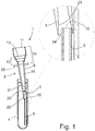
- the pipetting device 1 for receiving medical samples, for example body fluids and in particular blood, is composed of a tube holder 2 and a capillary tube 3 which is cylindrical on the inside and outside.
- the tube holder 2 on the one hand and the capillary tube 3 on the other hand are separate components, that is to say they are manufactured independently of one another.
- the capillary tube 3 can be located in a storage container 4, for example a test tube or a sample tube, before the sample is taken up or the sample is dispensed. Of course, several such capillary tubes 3 can also be present therein.
- the opening thereof is pressed against one end of the capillary tube 3.
- a conically shaped inlet slope on the inside of the channel section 5 serves as an important aid for receiving the capillary tube 3 from the storage container 4.
- the bottom 30 of the storage container 4 has the function of the abutment.
- the tube holder 2 is composed of several sections arranged one behind the other and in flow connection with one another, namely a channel section 5, a connecting section 6 and a radially widened section 10.
- Flow connection here means the possibility of the fluid flowing into or out of the pipetting device 1 when it is sucked in or emptied.
- the tube holder 2, facing the capillary tube 3, is closed by a channel section 5 open towards the capillary tube 3.
- the channel section 5 serves to receive and fasten the capillary tube 3.
- the connecting section 6 is in one piece with a radially widened section 10.
- the radially widened section 10 has a volume that is many times greater than that of the interior of the capillary tube. It is provided with an opening 11 facing away from the capillary tube 3 or the channel section 5, the opening cross section of which is, for example, the same as the cross section of the radially widened section 10.
- Part of the radially expanded section 10 is a reversibly deformable, accordion-like shaped compression section 12.
- the compression section 12 consists of zigzag-shaped segments 13 of different diameters transversely to the longitudinal axis of the pipetting device 1.
- the compression section 12 is integral both with the connecting section 6 and with the radially enlarged section 10.
- the compression section 12 can be deformed from an originally relaxed state into a longitudinally compressed state.
- the volume of air in the section 10 is reduced, so that air flows from the tube holder 2 to the capillary tube 3 and displaces the fluid present there.
- the common volume of the connecting section 6 and the radially widened section 10 is a multiple of the capillary volume enclosed by the capillary tube 3.
- the compression section 12 is actuated by applying pressure with a finger or the thumb, the opening 11 being closed by the finger or thumb at the same time. After the compression, the upsetting section 12 expands again due to the elasticity of the material and reversibly returns to its starting position. This can vary depending on the material. For single-use use, however, reversible deformability is not essential.
- the channel section 5 and the connecting section 6 taper towards the capillary tube 3.
- the shell shape on the inside in the area of the channel section 5 and the connecting section 6 is conical.
- the interior space 15, 16 extending through the channel section 5 and the connecting section 6 is provided with a constriction 20 at the connection point between the channel section 5 and the connection point 6.
- the constriction 20 is an integrally formed, radially inwardly pointing collar or flange 20 which, however, leaves a flow passage free in its center.
- a fluid stop 22 is inserted or fastened in the area of the central opening 21 of the constriction 20.
- the fluid stop 22 is characterized in that it compresses through contact with moisture.
- the fluid contact with the fluid stop 22 can be caused, for example, by fluid spraying vertically upwards from the capillary tube 3, for example during a suction process.
- the fluid stop 22 is largely impermeable to liquids, it is permeable to gas exchange. This is necessary, for example, in order to empty the capillary tube 3 under gas pressure, brought about by pressure on the compression section 12 with the opening 11 closed.
- the inner wall 23 of the channel section 5 is designed to widen conically towards its open end 24.
- the inner diameter of the channel section 5 is therefore smaller in the area of the constriction 20 than in the area of the opening 24. Because the inner diameter widens towards the capillary tube 3, similar to a funnel, and it is in particular larger than the cylindrical outer diameter of the capillary tube 3, the picking up of the capillary tube 3 is considerably facilitated.
- Fig. 1 shows that the capillary tube 3 is not yet attached even if it partially protrudes into the channel section 5.
- the final fastening of the capillary tube 3 in the channel section 5 of the tube holder 2 is carried out by axially pressing the tube holder 2 against the capillary tube 3.
- the conical inner wall 23 of the channel section 5 slides along the capillary tube 3 until a slight press fit is finally achieved.
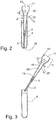
- Such a seat of the capillary tube 3 is for example in Figure 2 to recognize.
- the capillary tube 3 does not necessarily abut the constriction 20 between the channel section 5 and the connecting section 6, even in a press fit.
- a rigid flange 25 formed in one piece on the outside of the connecting section 6 is used to grip and apply the counterpressure when emptying the capillary tube 3. This is arranged on the end of the connecting section 6 facing away from the capillary tube 3. The flange 25 surrounds the tube holder 2 completely or partially.
- the open end 32 of the capillary tube 3 is brought into contact with the blood (drop) 31 or with the medical sample.
- the fluid reaches the capillary tube 3 exclusively by capillary traction.
- the flange 25 molded onto the tube holder 2 serves as a gripping and holding device.
- the pipetting device 1, such as Figure 5 shows, positioned over a suitable collecting receptacle 33 or over a laboratory sample strip 34.
- the opening 11 of the radially widened section 10 is covered by a finger or thumb during the emptying process, and is thus closed.
- the deformable compression section 12 is compressed by the pressure of the finger or thumb, so that the folds are pushed together and the enclosed volume is reduced.
- the deformable section 12 is thus compressed and the fluid is thus pressed out of the capillary tube 3.
- the emptying process is exemplified in Figure 6 for emptying in a collecting container 33 and in Figure 7 shown on a test strip 34 for emptying.
Landscapes
- Health & Medical Sciences (AREA)
- Life Sciences & Earth Sciences (AREA)
- Molecular Biology (AREA)
- Surgery (AREA)
- Biophysics (AREA)
- Pathology (AREA)
- Engineering & Computer Science (AREA)
- Biomedical Technology (AREA)
- Heart & Thoracic Surgery (AREA)
- Medical Informatics (AREA)
- Hematology (AREA)
- Physics & Mathematics (AREA)
- Animal Behavior & Ethology (AREA)
- General Health & Medical Sciences (AREA)
- Public Health (AREA)
- Veterinary Medicine (AREA)
- Clinical Laboratory Science (AREA)
- Chemical & Material Sciences (AREA)
- Chemical Kinetics & Catalysis (AREA)
- Dermatology (AREA)
- Sampling And Sample Adjustment (AREA)
- Measurement Of The Respiration, Hearing Ability, Form, And Blood Characteristics Of Living Organisms (AREA)
Description
- Im Allgemeinen betrifft die Erfindung eine Pipettiervorrichtung zur Aufnahme und Abgabe von medizinischen Proben, zum Beispiel Körperfluiden, mit einem zylindrischen Kapillarröhrchen und einem Röhrchenhalter, wobei der Rörchenhalter besteht aus
- einem Kanalabschnitt zur Aufnahme des Kapillarröhrchens,
- einem radial erweiterten Abschnitt, der dem Kanalabschnitt abgewandt mit einer Öffnung versehen ist,
- einem Verbindungsabschnitt, welcher eine Strömungsverbindung zwischen dem Kanalabschnitt und dem radial erweiterten Abschnitt bildet,
- Aus der
WO 2011/075075 ist eine Pipettiervorrichtung zur Flüssigkeitsaufnahme von bis zu 200 µL bekannt. Die dort gezeigte Mikropipette setzt sich aus einem Kapillarröhrchen und einem das Kapillarröhrchen an einem Ende aufnehmenden Rohrabschnitt zusammen. Der Rohrabschnitt schließt an seinem anderen Ende mit einer Gasaustauscheinheit ab. Diese wird zu ihrer Befestigung über einen an dem Rohrabschnitt angeformten Flansch gestülpt. Ein an dem Rohrabschnitt ausgebildeter Flansch dient der Handhabung der Pipettiervorrichtung. Zum Ansaugen von Flüssigkeit wird zunächst die innerhalb der Austauscheinheit befindliche Luft herausgedrückt und die Flüssigkeit durch Unterdruck oder unter Kapillarzug in das Kapillarröhrchen aufgesogen. Zur späteren Abgabe des Fluids wird die Gasaustauscheinheit durch Druck mit dem Finger betätigt. Um ein Eindringen von Wasser, Blut oder Körperfluiden in den Rohrabschnitt zu vermeiden, ist dieser aus einem weniger hydrophilen Material gefertigt als das Kapillarröhrchen. - Von Nachteil ist, dass zunächst die aus Silikon oder Gummi bestehende Gasaustauscheinheit vom Anwender auf den Rohrabschnitt gestülpt werden muss. Für dieses Überstülpen ist zwar ein gewisser Ausgleich des in der Gasaustauscheinheit eingeschlossenen Luftvolumens vorgesehen, jedoch kann es, wenn sich im Kapillarröhrchen bereits eine Flüssigkeitsprobe befindet, doch zu einem teilweisen Austreten und damit einem vorzeitigen Flüssigkeitsverlust kommen.
- Außerdem ist das Aufstülpen der Gasaustauscheinheit ein zusätzlicher Verfahrensschritt. Weiterhin bedarf diese Konstruktion mehrerer Schritte zur Fertigung der Einzelkomponenten. Schließlich kann die Gefahr einer Kontamination der Gasaustauscheinheit mit angesaugtem Fluid nicht ausgeschlossen werden, was insbesondere bei Mehrfachverwendung der Gasaustauscheinheit problematisch sein kann.
- Aus der
DE 10 2004 021 741 A1 und derWO 2005/094681 A1 sind Pipettiervorrichtungen bekannt, bei welchen ein Kapillarröhrchen oder eine Kanüle mit einem seiner Enden in eine Öffnung eines langgestreckten Röhrchenhalters eingesetzt wird. In dessen Hauptkörper ist längsbeweglich ein Kolben angeordnet. Dabei kann der Kolben eine Öffnung zur Entlüftung des Hauptkörpers besitzen, oder er ist leicht beabstandet zur Innenwand des Hauptkörpers angeordnet. Zum Aufnehmen von zum Beispiel Blut ist der Kolben nahezu vollständig aus dem den Kolben führenden Zylinderabschnitt des Hauptkörpers herausgezogen. Die Mikropipette bzw. die Kapillare oder Kanüle wird mit ihrem offenen Ende solange in Kontakt zum Fluid gebracht, bis durch Kapillarzug das gewünschte Fülllevel im Kapillarröhrchen erreicht ist. Durch Herunterdrücken des Kolbens, bei durch einen Finger verschlossener Öffnung, wird das Kapillarröhrchen entleert. Bei Vorrichtungen dieser Art ist es von Nachteil, dass der Kolben als separates Bauteil gefertigt ist, und somit zunächst montiert werden muss - Auch
EP-A-0 232 517 ,WO 99/51350 EP-A-2 031 408 undDE 20 2004 004951 U beschreiben Pipettiervorrichtungen. - Der Erfindung liegt die Aufgabe zugrunde, eine mit geringem Aufwand herstellbare Pipettiervorrichtung der eingangs genannten Art bereitzustellen, welche die Handhabung erleichtert und die Sicherheit für den Anwender erhöht.
- Zur Lösung der Aufgabe wird eine Pipettiervorrichtung mit den Merkmalen des Anspruchs 1 vorgeschlagen.
- Vorteilhafte Ausgestaltungen der Pipettiervorrichtung sind in den Unteransprüchen angegeben.
- Die erfindungsgemäße Pipettiervorrichtung ist zur Aufnahme und Abgabe von medizinischen Proben, insbesondere Körperfluiden wie z. B. Blut, geeignet. Auch können andere Flüssigkeiten, Dispersionen, Emulsionen oder gar aufgewirbelte Suspensionen mit einer solchen Pipettiervorrichtung aufgenommen werden. Die Probenauswahl ist nicht auf medizinische Proben beschränkt.
- Die Pipettiervorrichtung zur Aufnahme und Abgabe von medizinischen Proben, zum Beispiel Körperfluiden, umfasst ein zylindrisches Kapillarröhrchen und einen Röhrchenhalter. Dieser besteht aus
- einem Kanalabschnitt zur Aufnahme des Kapillarröhrchens,
- einem radial erweiterten Abschnitt, der dem Kanalabschnitt abgewandt mit einer Öffnung versehen ist,
- einem Verbindungsabschnitt, welcher eine Strömungsverbindung zwischen dem Kanalabschnitt und dem radial erweiterten Abschnitt bildet,
- Hierbei ist der Röhrchenhalter zur Verkleinerung des gemeinsamen Volumens mit einem in Längsrichtung des Röhrchenhalters verformbar ausgebildeten Stauchabschnitt, der einstückig mit dem Verbindungsabschnitt und mit dem radial erweiterten Abschnitt ist, versehen. Vorzugsweise ist der Stauchabschnitt reversibel verformbar ausgebildet, d. h. er nimmt nach der Verformung wieder seine ursprüngliche Form an.
- Außerdem ist der Kanalabschnitt einstückig mit dem Verbindungsabschnitt ausgebildet. Dies erhöht die Stabilität der Gesamtkonstruktion, vereinfacht die Fertigung und gewährleistet eine sichere Aufnahme des Kapillarröhrchens in dem Kanalabschnitt des Röhrchenhalters.
- Der Röhrchenhalter kann, einschließlich des radial erweiterten Abschnitts und des Stauchabschnitts, in einem einzigen Schritt als ein einstückiges, d. h. materialeinheitliches Teil hergestellt werden, z. B. in einem Spritzgussverfahren. Dies ist insbesondere für die preiswerte Massenproduktion der Einweg-Pipettiervorrichtung günstig. Auch wird die Handhabung der Pipettiervorrichtung erleichtert, da ein separates Aufstülpen einer Gasaustauscheinheit durch den Anwender, wie bei der aus der
WO 2011/075075 bekannten Mikropipette, entfällt. Darüber hinaus steigt auch die Zuverlässigkeit der Pipettiervorrichtung, da kein Aufsetzen einer Gasaustauscheinheit gemäß derWO 2011/075075 oder die Montage eines Kolbens gemäß derDE 10 2004 021 741 A1 oder derWO 2005/094681 A1 notwendig ist. Die Gefahr eines unsachgemäßen Zusammenbaus oder gar einer Beschädigung bei der Montage entfällt. - Zwischen dem Kanalabschnitt und dem Verbindungsabschnitt ist eine Verengung ausgebildet. Diese dient einerseits der Materialstabilisierung, dient gleichzeitig aber auch als Abdichtung des Innenraums des Verbindungsabschnitts gegen übertretendes oder spritzendes Fluid aus dem Kapillarröhrchen beziehungsweise dem Kanalabschnitt. Weiterhin kann die Verengung auch Befestigungsflansch für Filter wie beispielsweise einen Fluid- oder Blutstopp sein.
- Ein solcher Fluidstopp kann entweder auf der dem Kapillarröhrchen zugewandten Seite oder auf der dem Kapillarröhrchen abgewandten Seite oder in der Verengung angeordnet sein. Die Verengung dient auch als Auflage- oder Befestigungsflansch für den Fluidstopp.
- Erfindungsgemäß ist ein für Luft oder Inertgas durchlässiger, aber für Flüssigkeiten und Feststoffe weitgehend undurchlässiger Fluidstopp im Bereich der Verengung versehen. Dadurch wird die Gefahr verringert, dass möglicherweise viral, bakteriell oder anders kontaminierte Fluide in den Verbindungsabschnitt eindringen und möglicherweise durch den einseitig offenen radial erweiterten Abschnitt nach außen dringen und gar den Anwender kontaminieren.
- In einer bevorzugten Ausgestaltung ist an dem Verbindungsabschnitt des Röhrchenhalters ein Flansch starr und einstückig angeformt. Dies ermöglicht dem Anwender ein sicheres Greifen und Halten der Pipettiervorrichtung. Außerdem bildet der Flansch ein Widerlager, an dem sich die Finger des Benutzers beim Entleeren der Pipettiervorrichtung abstützen können.
- In einer weiteren Ausgestaltung ist der Fluidstopp derart ausgebildet, dass er sich durch den Kontakt mit Feuchtigkeit verdichtet. So kann die ohnehin in den Proben auftretende Feuchtigkeit bei Kontakt mit dem Fluidstopp in-situ ausgenutzt werden. Dies erhöht die Sicherheit bei der Handhabung und schützt den Anwender vor Kontamination mit der Probe.
- In einer weiteren Ausgestaltung ist die Innenseite des Kanalabschnittes zu dessen offenem Ende hin konisch erweitert ausgebildet. Durch den konisch erweiterten Endbereich wird die Aufnahme des Kapillarröhrchens erleichtert, welches von geringerem Außendurchmesser als der Durchmesser der Innenwandung des konisch erweiterten Endes ist. Selbst wenn nur ein kurzer Abschnitt des Kapillarröhrchens bei dessen Aufnahme erfasst wird, gleitet dieser längs der konischen Öffnung in den Kanalabschnitt hinein, und kann dann anschließend durch Klemmen gehalten werden.
- Trotz des innen konisch verlaufenden Kanalabschnitts, verjüngt sich der Röhrchenhalter von außen in Richtung des Kapillarröhrchens. Dabei verjüngen sich sowohl der Verbindungsabschnitt als auch der Kanalabschnitt, wodurch eine hohe Stabilität des Röhrchenhalters sichergestellt ist.
- Vorzugsweise ist der durch Stauchen verformbare Abschnitt von Ziehharmonika-förmiger Gestalt. Dabei setzt er sich einstückig aus zickzackförmig einander abwechselnden Wandabschnitten zusammen. Bevorzugt nimmt der Durchmesser der zickzackförmigen Wandabschnitte in der dem Kapillarröhrchen abgewandten Richtung zu. Der Vorteil dieser Anordnung ist die Möglichkeit der einstückigen Fertigung und des zuverlässigen, vorzugsweise reversiblen Stauchens beim Zusammenschieben der Falten. Die einstückige Fertigung erspart Materialkosten und verbessert für den Anwender die Nutzung.
- Vorzugsweise ist der Röhrchenhalter samt Kanalabschnitt, Verbindungsabschnitt, dem radial erweiterten Abschnitt und dem Stauchabschnitt ein Spritzgussteil aus einem polyolefinischen Material. Insbesondere bevorzugt ist dabei Polyethylen (PE), beschränkt sich aber nicht auf dessen Einsatz. Das Spritzgussverfahren ermöglicht eine kostengünstige und schnelle Massenfertigung. Aus den Materialeigenschaften von Polyethylen ergibt sich für den Röhrchenhalter samt den genannten Abschnitten ein relativ geringes Gewicht, eine Ermüdungsbeständigkeit sowie eine chemische Inertheit gegenüber den meisten organischen Lösungsmitteln.
- Bevorzugt ist es, das Kapillarröhrchen aus transparentem Polyvinylchlorid (PVC) oder Polyethylenterephthalat (PET) zu fertigen. Dieses ist chemisch relativ inert und widerstandsfähig. Die Verarbeitung erfolgt durch Extrusion, wodurch die Kapillarröhrchen kostengünstig und in hoher Stückzahl herstellbar sind. Die Kapillarröhrchen können auch aus anderen Materialien bestehen, beispielsweise Glas.
- Eine Ausführungsform der erfindungsgemäßen Pipettiervorrichtung wird im Folgenden anhand der Zeichnungen näher erläutert. Es zeigen:
- Fig. 1
- eine Schnittdarstellung der Pipettiervorrichtung während der Aufnahme des Kapillarröhrchens aus einem Aufbewahrungsbehältnis, samt einer Vergrößerung;
- Fig. 2
- eine Schnittdarstellung der Pipettiervorrichtung mit im Behältnis des Kapillarröhrchens aufgenommenem Kapillarröhrchen;
- Fig. 3
- eine Schnittdarstellung der Pipettiervorrichtung nach der Aufnahme des Kapillarröhrchens aus dem Behältnis;
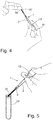
- Fig. 4
- schematische Darstellung der Aufnahme eines Bluttropfens mit der Pipettiervorrichtung;
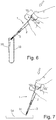
- Fig. 5
- schematische Darstellung der Pipettiervorrichtung kurz vor dem Entleeren des aufgenommenen Fluids in ein Probenbehältnis;
- Fig. 6
- schematische Darstellung der Pipettiervorrichtung beim Entleeren des aufgenommenen Fluids in ein Probenbehältnis;
- Fig. 7
- schematische Darstellung der Pipettiervorrichtung bei der teilweisen Abgabe des aufgenommenen Fluids auf einen Laborteststreifen.
- Die erfindungsgemäße Pipettiervorrichtung 1 zur Aufnahme von medizinischen Proben, zum Beispiel Körperfluiden und insbesondere Blut, setzt sich aus einem Röhrchenhalter 2 und einem innen und außen zylindrischen Kapillarröhrchen 3 zusammen. Wie aus
Figur 1 ersichtlich, sind der Röhrchenhalter 2 einerseits und das Kapillarröhrchen 3 andererseits separate Bauteile, sie werden also unabhängig voneinander gefertigt. - Das Kapillarröhrchen 3 kann sich vor der Probenaufnahme oder der Probenabgabe in einem Aufbewahrungsbehältnis 4 befinden, etwa einem Reagenzglas oder einem Probenröhrchen. Selbstverständlich können darin auch mehrere derartige Kapillarröhrchen 3 vorhanden sein.
- Zur Aufnahme und zur Befestigung des Kapillarröhrchens 3 am Röhrchenhalter 2 wird dieser mit seiner Öffnung gegen das eine Ende des Kapillarröhrchens 3 gedrückt. Dabei dient eine konisch gestaltete Einlaufschräge innen am Kanalabschnitt 5 als wichtige Hilfe zum Aufnehmen des Kapillarröhrchens 3 aus dem Aufbewahrungsbehältnis 4. Wie in
Figur 2 gezeigt, hat der Boden 30 des Aufbewahrungsbehältnisses 4 dabei die Funktion des Widerlagers. Sobald durch axialen Druck gegen das so abgestützte Kapillarröhrchen 3 ein leichter Presssitz des Kapillarröhrchens im Röhrchenhalter 2 erreicht ist, kann die Pipettiervorrichtung 1 verwendet werden. - Der Röhrchenhalter 2 setzt sich aus mehreren hintereinander angeordneten und miteinander in Strömungsverbindung stehenden Abschnitten zusammen, nämlich einem Kanalabschnitt 5, einem Verbindungsabschnitt 6 und einem radial erweiterten Abschnitt 10. Strömungsverbindung meint hier die Strömungsmöglichkeit des Fluids beim Ansaugen oder Entleeren in bzw. aus der Pipettiervorrichtung 1.
- Der Röhrchenhalter 2 ist, dem Kapillarröhrchen 3 zugewandt, durch einen zum Kapillarröhrchen 3 hin offenen Kanalabschnitt 5 abgeschlossen. Der Kanalabschnitt 5 dient zur Aufnahme und Befestigung des Kapillarröhrchens 3. An den Kanalabschnitt 5 schließt sich einstückig der Verbindungsabschnitt 6 an, der die Strömungsverbindung zwischen dem Kanalabschnitt 5 und dem radial erweiterten Abschnitt 10 bildet. Der Verbindungsabschnitt 6 ist einstückig mit einem radial erweiterten Abschnitt 10. Der radial erweiterte Abschnitt 10 weist ein im Vergleich zu dem Inneren des Kapillarröhrchens vielfach größeres Volumen auf. Er ist dem Kapillarröhrchen 3 bzw. dem Kanalabschnitt 5 abgewandt mit einer Öffnung 11 versehen, deren Öffnungsquerschnitt zum Beispiel gleich ist dem Querschnitt des radial erweiterten Abschnitts 10.
- Bestandteil des radial erweiterten Abschnitts 10 ist ein reversibel verformbarer, Ziehharmonika-artig geformter Stauchabschnitt 12. Der Stauchabschnitt 12 besteht aus zickzackförmig aneinandergereihten Segmenten 13 unterschiedlichen Durchmessers quer zur Längsachse der Pipettiervorrichtung 1. Der Stauchabschnitt 12 ist einstückig sowohl mit dem Verbindungsabschnitt 6 als auch mit dem radial erweiterten Abschnitt 10.
- Der Stauchabschnitt 12 kann aus einem ursprünglich relaxierten Zustand in einen in Längsrichtung komprimierten Zustand verformt werden. Dabei reduziert sich das Luftvolumen in dem Abschnitt 10, so dass Luft aus dem Röhrchenhalter 2 zu dem Kapillarröhrchen 3 hin strömt, und das dort vorhandene Fluid verdrängt. Dabei beträgt das gemeinsame Volumen des Verbindungsabschnitts 6 und des radial erweiterten Abschnitts 10 ein Mehrfaches des von dem Kapillarröhrchen 3 umschlossenen Kapillarvolumens.
- Die Betätigung des Stauchabschnitts 12 wird über Druck mit einem Finger oder dem Daumen vollzogen, wobei zugleich die Öffnung 11 durch den Finger bzw. Daumen verschlossen ist. Nach der Kompression dehnt sich der Stauchabschnitt 12 aufgrund der Materialelastizität wieder aus und gelangt reversibel zurück in seine Ausgangslage. Dies kann je nach Material variieren. Für einen Einweg-Gebrauch allerdings ist eine reversible Verformbarkeit nicht zwingend.
- Wie unter anderem
Figur 1 zeigt, verjüngen sich der Kanalabschnitt 5 und der Verbindungsabschnitt 6 zu dem Kapillarröhrchen 3 hin. Die Mantelform innen im Bereich des Kanalabschnitts 5 und des Verbindungsabschnitts 6 ist kegelartig. - Der durch den Kanalabschnitt 5 und den Verbindungsabschnitt 6 sich erstreckende Innenraum 15, 16 ist an der Verbindungsstelle zwischen Kanalabschnitt 5 und Verbindungsstelle 6 mit einer Verengung 20 versehen. Die Verengung 20 ist ein einstückig angeformter, radial nach innen weisender Bund oder Flansch 20, der jedoch in seiner Mitte einen Strömungsdurchgang freilässt.
- Im Bereich der zentralen Öffnung 21 der Verengung 20 ist ein Fluidstopp 22 eingesetzt oder befestigt. Der Fluidstopp 22 zeichnet sich dadurch aus, dass er sich durch den Kontakt mit Feuchtigkeit verdichtet. Der Fluidkontakt mit dem Fluidstopp 22 kann beispielsweise durch vertikal nach oben spritzendes Fluid aus dem Kapillarröhrchen 3 bedingt sein, etwa bei einem Ansaugprozess. Während der Fluidstopp 22 weitgehend undurchlässig für Flüssigkeiten ist, ist er durchlässig für den Gasaustausch. Dies ist beispielsweise notwendig, um das Kapillarröhrchen 3 unter Gasdruck zu entleeren, bewerkstelligt durch Druck auf den Stauchabschnitt 12 bei verschlossener Öffnung 11.
- Wie die Vergrößerung in
Fig. 1 zu erkennen gibt, ist die Innenwandung 23 des Kanalabschnittes 5 zu dessen offenem Ende 24 hin konisch erweitert ausgebildet. Der Innendurchmesser des Kanalabschnitts 5 ist also im Bereich der Verengung 20 kleiner als im Bereich der Öffnung 24. Dadurch, dass sich der Innendurchmesser zu dem Kapillarröhrchen 3 hin erweitert, ähnlich einem Trichter, und er insbesondere größer ist als der zylindrische Außendurchmesser des Kapillarröhrchens 3, wird das Aufnehmen des Kapillarröhrchens 3 beträchtlich erleichtert. - Wie die Vergrößerung in
Fig. 1 jedoch zeigt, ist das Kapillarröhrchen 3 auch bei teilweisem Hineinragen in den Kanalabschnitt 5 noch nicht befestigt. Die endgültige Befestigung des Kapillarröhrchens 3 im Kanalabschnitt 5 des Röhrchenhalters 2 wird durch axiales Drücken des Röhrchenhalters 2 gegen das Kapillarröhrchen 3 vollzogen. Dabei gleitet die konische Innenwandung 23 des Kanalabschnitts 5 entlang des Kapillarröhrchens 3, bis schließlich ein leichter Presssitz erreicht ist. Ein solcher Sitz des Kapillarröhrchens 3 ist beispielsweise inFigur 2 zu erkennen. Das Kapillarröhrchen 3 stößt auch im Presssitz nicht notwendigerweise an die Verengung 20 zwischen Kanalabschnitt 5 und Verbindungsabschnitt 6 an. - Zum Greifen und zum Aufbringen des Gegendrucks beim Entleeren des Kapillarröhrchens 3 dient ein einstückig außen an den Verbindungsabschnitt 6 angeformter, starrer Flansch 25. Dieser ist an dem dem Kapillarröhrchen 3 abgewandten Ende des Verbindungsabschnitts 6 angeordnet. Der Flansch 25 umgibt den Röhrchenhalter 2 vollständig oder partiell.
- Zur Aufnahme von medizinischen Proben, wie in
Figur 4 beispielhaft anhand eines an einem Finger eines Probanden befindlichen Bluttropfens 31 gezeigt, wird das offene Ende 32 des Kapillarröhrchens 3 in Kontakt mit dem Blut(tropfen) 31 bzw. mit der medizinischen Probe gebracht. Das Fluid gelangt ausschließlich durch Kapillarzug in das Kapillarröhrchen 3. Der an dem Röhrchenhalter 2 angeformte Flansch 25 dient hierbei als Greif- und Haltevorrichtung. - Zum Entleeren des Kapillarröhrchens 3 wird die Pipettiervorrichtung 1, wie
Figur 5 zeigt, über einem geeigneten Auffangbehältnis 33 oder über einem Labor-Probenstreifen 34 positioniert. Die Öffnung 11 des radial erweiterten Abschnitts 10 ist beim Entleerungsvorgang von einem Finger oder Daumen bedeckt, und somit verschlossen. Zugleich wird der verformbare Stauchabschnitt 12 durch die Druckkraft des Fingers oder Daumens komprimiert, so dass die Falten zusammengeschoben werden und sich das eingeschlossene Volumen verringert. Der verformbare Abschnitt 12 wird also gestaucht, und so das Fluid aus dem Kapillarröhrchen 3 herausgedrückt. Der Entleerungsvorgang ist beispielhaft inFigur 6 für die Entleerung in einem Auffangbehältnis 33 und inFigur 7 für die Entleerung auf einem Teststreifen 34 dargestellt. -
- 1
- Pipettiervorrichtung
- 2
- Röhrchenhalter
- 3
- Kapillarröhrchen
- 4
- Aufbewahrungsbehältnis
- 5
- Kanalabschnitt
- 6
- Verbindungsabschnitt
- 10
- radial erweiterter Abschnitt
- 11
- Öffnung
- 12
- Stauchabschnitt
- 13
- Segment
- 14
- Mantel
- 15
- Innenraum
- 16
- Innenraum
- 20
- Verengung
- 21
- Öffnung
- 22
- Fluidstopp
- 23
- Innenwandung
- 24
- offenes Ende
- 25
- Flansch
- 30
- Boden
- 31
- Blut(tropfen)
- 32
- offenes Ende
- 33
- Auffangbehältnis
- 34
- Teststreifen, Labor-Probenstreifen
Claims (8)
- Pipettiervorrichtung (1) zur Aufnahme und Abgabe von medizinischen Proben, zum Beispiel Körperfluiden, mit einem zylindrischen Kapillarröhrchen (3) und einem Röhrchenhalter (2), wobei der Rörchenhalter (2) besteht aus- einem Kanalabschnitt (5) zur Aufnahme des Kapillarröhrchens (3),- einem radial erweiterten Abschnitt (10), der dem Kanalabschnitt (5) abgewandt mit einer Öffnung (11) versehen ist,- einem Verbindungsabschnitt (6), welcher eine Strömungsverbindung zwischen dem Kanalabschnitt (5) und dem radial erweiterten Abschnitt (10) bildet,wobei das gemeinsame Volumen des Verbindungsabschnitts (6) und des radial erweiterten Abschnitts (10) ein Mehrfaches des von dem Kapillarröhrchen (3) umschlossenen Kapillarvolumens beträgt und verkleinerbar ist, dadurch gekennzeichnet, dass der Röhrchenhalter (2) zur Verkleinerung des gemeinsamen Volumens mit einem in Längsrichtung des Röhrchenhalters (2) verformbar ausgebildeten Stauchabschnitt (12) versehen ist, der einstückig mit dem Verbindungsabschnitt (6) und mit dem radial erweiterten Abschnitt (10) ist, dass der Kanalabschnitt (5) einstückig mit dem Verbindungsabschnitt (6) ausgebildet ist, und dass zwischen dem Kanalabschnitt (5) und dem Verbindungsabschnitt (6) eine Verengung ausgebildet ist, wobei im Bereich der Verengung (20) ein gasdurchlässiger aber für Flüssigkeiten weitgehend undurchlässiger Fluidstopp (22) angeordnet ist.
- Pipettiervorrichtung nach Anspruch 1, gekennzeichnet durch einen starr und einstückig an dem Verbindungsabschnitt (6) angeformten Flansch (25) zum Greifen der Pipettiervorrichtung (1).
- Pipettiervorrichtung nach einem der vorangehenden Ansprüche, dadurch gekennzeichnet, dass der Fluidstopp (22) als sich durch den Kontakt mit Feuchtigkeit verdichtend ausgebildet ist.
- Pipettiervorrichtung nach einem der vorangehenden Ansprüche, dadurch gekennzeichnet, dass die Innenwandung (23) des Kanalabschnittes (5) zu dessen offenem Ende (24) hin konisch erweitert ausgebildet ist.
- Pipettiervorrichtung nach einem der vorangehenden Ansprüche, dadurch gekennzeichnet, dass sich der Querschnitt des Verbindungsabschnittes (6) zu dem Kanalabschnitt (5) hin verjüngt.
- Pipettiervorrichtung nach einem der vorangehenden Ansprüche, dadurch gekennzeichnet, dass der verformbare Abschnitt (12) von Ziehharmonika-förmiger Gestalt ist.
- Pipettiervorrichtung nach einem der vorangehenden Ansprüche, dadurch gekennzeichnet, dass der Röhrchenhalter (2) samt Kanalabschnitt (5), Verbindungsabschnitt (6), dem radial erweiterten Abschnitt (10) und dem Stauchabschnitt (12) ein Spritzgussteil aus polyolefinischem Material, vorzugsweise aus Polyethylen, ist.
- Pipettiervorrichtung nach einem der vorangehenden Ansprüche, dadurch gekennzeichnet, dass das Kapillarröhrchen (3) aus transparentem Polyvinylchlorid oder Polyethylenterephthalat besteht.
Applications Claiming Priority (1)
| Application Number | Priority Date | Filing Date | Title |
|---|---|---|---|
| DE102016109536.2A DE102016109536A1 (de) | 2016-05-24 | 2016-05-24 | Kapillarentleerungshilfe |
Publications (2)
| Publication Number | Publication Date |
|---|---|
| EP3248683A1 EP3248683A1 (de) | 2017-11-29 |
| EP3248683B1 true EP3248683B1 (de) | 2021-04-07 |
Family
ID=58698956
Family Applications (1)
| Application Number | Title | Priority Date | Filing Date |
|---|---|---|---|
| EP17168980.5A Active EP3248683B1 (de) | 2016-05-24 | 2017-05-02 | Kapillarentleerungshilfe |
Country Status (2)
| Country | Link |
|---|---|
| EP (1) | EP3248683B1 (de) |
| DE (1) | DE102016109536A1 (de) |
Families Citing this family (3)
| Publication number | Priority date | Publication date | Assignee | Title |
|---|---|---|---|---|
| AT527611A1 (de) * | 2023-10-05 | 2025-04-15 | Tagtron Gmbh | Kapillarhalter |
| GB202318356D0 (en) * | 2023-11-30 | 2024-01-17 | Osler Diagnostics Ltd | Liquid collection device and liquid handling device configured to receive a liquid collection device |
| CN118950118B (zh) * | 2024-07-19 | 2026-02-06 | 南京航空航天大学 | 通过冷冻毛细管产生微液滴的装置及方法 |
Family Cites Families (9)
| Publication number | Priority date | Publication date | Assignee | Title |
|---|---|---|---|---|
| DE3614085A1 (de) * | 1985-12-12 | 1987-06-19 | Hirschmann Glasgeraete | Pipette |
| DE3701250A1 (de) * | 1987-01-17 | 1988-07-28 | Carsten A Carstensen | Dosierpipette |
| DE29806142U1 (de) * | 1998-04-03 | 1998-06-18 | november Aktiengesellschaft, Gesellschaft für Molekulare Medizin, 91056 Erlangen | Vorrichtung zur Aufnahme und Abgabe einer definierten Flüssigkeitsmenge |
| DE10128460A1 (de) * | 2001-06-12 | 2003-01-02 | Michael Licht | Vorrichtung und Verfahren zum Sammeln von kleinen wässrigen Flüssigkeitsproben |
| DE202004004951U1 (de) | 2004-03-26 | 2004-08-19 | Sarstedt Ag & Co. | Vorrichtung zur Entnahme von Kapillarblut |
| DE102004021741B4 (de) | 2004-04-30 | 2012-09-20 | Sarstedt Ag & Co. | Blutentnahmevorrichtung, insbesondere für Neugeborene und Kleinkinder oder Kleintiere |
| JP5122091B2 (ja) * | 2006-06-13 | 2013-01-16 | ユニバーサル・バイオ・リサーチ株式会社 | 担体封入変形容器、担体封入変形容器処理装置、および担体封入変形容器処理方法 |
| WO2011075075A1 (en) | 2009-12-18 | 2011-06-23 | Zafena Ab | Micropipette |
| US10137445B2 (en) * | 2015-01-06 | 2018-11-27 | Gunnar Magnusson | Single use capillary micropipette for dispensing a defined volume of a liquid |
-
2016
- 2016-05-24 DE DE102016109536.2A patent/DE102016109536A1/de not_active Withdrawn
-
2017
- 2017-05-02 EP EP17168980.5A patent/EP3248683B1/de active Active
Non-Patent Citations (1)
| Title |
|---|
| None * |
Also Published As
| Publication number | Publication date |
|---|---|
| EP3248683A1 (de) | 2017-11-29 |
| DE102016109536A1 (de) | 2017-11-30 |
Similar Documents
| Publication | Publication Date | Title |
|---|---|---|
| EP2985015B1 (de) | Spritzenadapter | |
| DE2824588C2 (de) | Verschließvorrichtung für ein Vakuumröhrchen zur Blutentnahme | |
| DE2138180C3 (de) | Zentrifugierrohr aus Kunststoff | |
| EP2425896B1 (de) | Spritze für den Gebrauch mit einer Dosiervorrichtung | |
| DE2719815A1 (de) | Medizinische spritze | |
| EP3248683B1 (de) | Kapillarentleerungshilfe | |
| DE2309547C3 (de) | Gerät zum Füllen und Entleeren eines Flüssigkeitsbehälters, z.B. einer Pipette | |
| EP3030348A1 (de) | Vorrichtung zum einbringen einer flüssigen probe in ein mikrofluidisches system | |
| EP0420013A1 (de) | Blutentnahmevorrichtung | |
| EP3962575B1 (de) | Medizinische fluidübertragungsvorrichtung | |
| DE10048126B4 (de) | Vorrichtung zur Entnahme und/oder Dosierung von Flüssigkeitsproben mittels Unterdruck, insbesondere für analytische Untersuchungen | |
| DE102004021741B4 (de) | Blutentnahmevorrichtung, insbesondere für Neugeborene und Kleinkinder oder Kleintiere | |
| DE2415618C3 (de) | Filtervorrichtung zum Trennen von Blutfraktionen | |
| EP1797920B1 (de) | Vorrichtung zur Aufnahme und zum Austragen einer fliessfähigen Substanz | |
| DE102007014418A1 (de) | Verfahren und Vorrichtung zum dosierten Ausbringen eines Mediums | |
| DE102011075026A1 (de) | Fluidhandhabungsvorrichtung mit vollständig entleerbarem fluidreservoir | |
| EP4599935A1 (de) | Pipette | |
| CH703213A1 (de) | Handbedienteil einer Absaugvorrichtung. | |
| DE69814045T2 (de) | Einweg-sicherheitsvorrichtung zur blutübertragung | |
| DE2039000A1 (de) | Verfahren und Vorrichtung zur Entnahme von Fluessigkeitsproben | |
| EP3683483B1 (de) | Anschlussstück zum anschliessen eines schlauches an einen getränkebeutel | |
| EP4438177A1 (de) | Testanordnung zum nachweis einer substanz | |
| AT519610B1 (de) | System und Verfahren zur sterilen Abnahme von Körperflüssigkeit | |
| EP0006581B1 (de) | Vorrichtung zur kontaminationsfreien Probenahme einer Flüssigkeit aus einem Tank | |
| DE1598181B1 (de) | Geraet zum ueberfuehren von proben einer koerperfluessigkeit oder eines anderen stroemungsfaehigen mediums von einem spender, insbesondere blut |
Legal Events
| Date | Code | Title | Description |
|---|---|---|---|
| PUAI | Public reference made under article 153(3) epc to a published international application that has entered the european phase |
Free format text: ORIGINAL CODE: 0009012 |
|
| STAA | Information on the status of an ep patent application or granted ep patent |
Free format text: STATUS: THE APPLICATION HAS BEEN PUBLISHED |
|
| AK | Designated contracting states |
Kind code of ref document: A1 Designated state(s): AL AT BE BG CH CY CZ DE DK EE ES FI FR GB GR HR HU IE IS IT LI LT LU LV MC MK MT NL NO PL PT RO RS SE SI SK SM TR |
|
| AX | Request for extension of the european patent |
Extension state: BA ME |
|
| STAA | Information on the status of an ep patent application or granted ep patent |
Free format text: STATUS: REQUEST FOR EXAMINATION WAS MADE |
|
| 17P | Request for examination filed |
Effective date: 20180516 |
|
| RBV | Designated contracting states (corrected) |
Designated state(s): AL AT BE BG CH CY CZ DE DK EE ES FI FR GB GR HR HU IE IS IT LI LT LU LV MC MK MT NL NO PL PT RO RS SE SI SK SM TR |
|
| STAA | Information on the status of an ep patent application or granted ep patent |
Free format text: STATUS: EXAMINATION IS IN PROGRESS |
|
| 17Q | First examination report despatched |
Effective date: 20180911 |
|
| GRAP | Despatch of communication of intention to grant a patent |
Free format text: ORIGINAL CODE: EPIDOSNIGR1 |
|
| STAA | Information on the status of an ep patent application or granted ep patent |
Free format text: STATUS: GRANT OF PATENT IS INTENDED |
|
| INTG | Intention to grant announced |
Effective date: 20201127 |
|
| RIC1 | Information provided on ipc code assigned before grant |
Ipc: B01L 3/02 20060101AFI20201113BHEP Ipc: A61B 5/15 20060101ALI20201113BHEP Ipc: B01L 9/06 20060101ALN20201113BHEP |
|
| GRAS | Grant fee paid |
Free format text: ORIGINAL CODE: EPIDOSNIGR3 |
|
| GRAA | (expected) grant |
Free format text: ORIGINAL CODE: 0009210 |
|
| STAA | Information on the status of an ep patent application or granted ep patent |
Free format text: STATUS: THE PATENT HAS BEEN GRANTED |
|
| AK | Designated contracting states |
Kind code of ref document: B1 Designated state(s): AL AT BE BG CH CY CZ DE DK EE ES FI FR GB GR HR HU IE IS IT LI LT LU LV MC MK MT NL NO PL PT RO RS SE SI SK SM TR |
|
| REG | Reference to a national code |
Ref country code: GB Ref legal event code: FG4D Free format text: NOT ENGLISH |
|
| REG | Reference to a national code |
Ref country code: CH Ref legal event code: EP Ref country code: AT Ref legal event code: REF Ref document number: 1378977 Country of ref document: AT Kind code of ref document: T Effective date: 20210415 |
|
| REG | Reference to a national code |
Ref country code: DE Ref legal event code: R096 Ref document number: 502017009955 Country of ref document: DE |
|
| REG | Reference to a national code |
Ref country code: IE Ref legal event code: FG4D Free format text: LANGUAGE OF EP DOCUMENT: GERMAN |
|
| REG | Reference to a national code |
Ref country code: NL Ref legal event code: FP |
|
| REG | Reference to a national code |
Ref country code: LT Ref legal event code: MG9D |
|
| PG25 | Lapsed in a contracting state [announced via postgrant information from national office to epo] |
Ref country code: LT Free format text: LAPSE BECAUSE OF FAILURE TO SUBMIT A TRANSLATION OF THE DESCRIPTION OR TO PAY THE FEE WITHIN THE PRESCRIBED TIME-LIMIT Effective date: 20210407 Ref country code: FI Free format text: LAPSE BECAUSE OF FAILURE TO SUBMIT A TRANSLATION OF THE DESCRIPTION OR TO PAY THE FEE WITHIN THE PRESCRIBED TIME-LIMIT Effective date: 20210407 Ref country code: HR Free format text: LAPSE BECAUSE OF FAILURE TO SUBMIT A TRANSLATION OF THE DESCRIPTION OR TO PAY THE FEE WITHIN THE PRESCRIBED TIME-LIMIT Effective date: 20210407 Ref country code: BG Free format text: LAPSE BECAUSE OF FAILURE TO SUBMIT A TRANSLATION OF THE DESCRIPTION OR TO PAY THE FEE WITHIN THE PRESCRIBED TIME-LIMIT Effective date: 20210707 |
|
| PG25 | Lapsed in a contracting state [announced via postgrant information from national office to epo] |
Ref country code: LV Free format text: LAPSE BECAUSE OF FAILURE TO SUBMIT A TRANSLATION OF THE DESCRIPTION OR TO PAY THE FEE WITHIN THE PRESCRIBED TIME-LIMIT Effective date: 20210407 Ref country code: IS Free format text: LAPSE BECAUSE OF FAILURE TO SUBMIT A TRANSLATION OF THE DESCRIPTION OR TO PAY THE FEE WITHIN THE PRESCRIBED TIME-LIMIT Effective date: 20210807 Ref country code: GR Free format text: LAPSE BECAUSE OF FAILURE TO SUBMIT A TRANSLATION OF THE DESCRIPTION OR TO PAY THE FEE WITHIN THE PRESCRIBED TIME-LIMIT Effective date: 20210708 Ref country code: SE Free format text: LAPSE BECAUSE OF FAILURE TO SUBMIT A TRANSLATION OF THE DESCRIPTION OR TO PAY THE FEE WITHIN THE PRESCRIBED TIME-LIMIT Effective date: 20210407 Ref country code: RS Free format text: LAPSE BECAUSE OF FAILURE TO SUBMIT A TRANSLATION OF THE DESCRIPTION OR TO PAY THE FEE WITHIN THE PRESCRIBED TIME-LIMIT Effective date: 20210407 Ref country code: PT Free format text: LAPSE BECAUSE OF FAILURE TO SUBMIT A TRANSLATION OF THE DESCRIPTION OR TO PAY THE FEE WITHIN THE PRESCRIBED TIME-LIMIT Effective date: 20210809 Ref country code: NO Free format text: LAPSE BECAUSE OF FAILURE TO SUBMIT A TRANSLATION OF THE DESCRIPTION OR TO PAY THE FEE WITHIN THE PRESCRIBED TIME-LIMIT Effective date: 20210707 Ref country code: PL Free format text: LAPSE BECAUSE OF FAILURE TO SUBMIT A TRANSLATION OF THE DESCRIPTION OR TO PAY THE FEE WITHIN THE PRESCRIBED TIME-LIMIT Effective date: 20210407 |
|
| REG | Reference to a national code |
Ref country code: DE Ref legal event code: R097 Ref document number: 502017009955 Country of ref document: DE |
|
| REG | Reference to a national code |
Ref country code: DE Ref legal event code: R082 Ref document number: 502017009955 Country of ref document: DE Representative=s name: JANKE SCHOLL PATENTANWAELTE PARTG MBB, DE |
|
| PG25 | Lapsed in a contracting state [announced via postgrant information from national office to epo] |
Ref country code: SM Free format text: LAPSE BECAUSE OF FAILURE TO SUBMIT A TRANSLATION OF THE DESCRIPTION OR TO PAY THE FEE WITHIN THE PRESCRIBED TIME-LIMIT Effective date: 20210407 Ref country code: SK Free format text: LAPSE BECAUSE OF FAILURE TO SUBMIT A TRANSLATION OF THE DESCRIPTION OR TO PAY THE FEE WITHIN THE PRESCRIBED TIME-LIMIT Effective date: 20210407 Ref country code: ES Free format text: LAPSE BECAUSE OF FAILURE TO SUBMIT A TRANSLATION OF THE DESCRIPTION OR TO PAY THE FEE WITHIN THE PRESCRIBED TIME-LIMIT Effective date: 20210407 Ref country code: RO Free format text: LAPSE BECAUSE OF FAILURE TO SUBMIT A TRANSLATION OF THE DESCRIPTION OR TO PAY THE FEE WITHIN THE PRESCRIBED TIME-LIMIT Effective date: 20210407 Ref country code: EE Free format text: LAPSE BECAUSE OF FAILURE TO SUBMIT A TRANSLATION OF THE DESCRIPTION OR TO PAY THE FEE WITHIN THE PRESCRIBED TIME-LIMIT Effective date: 20210407 Ref country code: DK Free format text: LAPSE BECAUSE OF FAILURE TO SUBMIT A TRANSLATION OF THE DESCRIPTION OR TO PAY THE FEE WITHIN THE PRESCRIBED TIME-LIMIT Effective date: 20210407 Ref country code: CZ Free format text: LAPSE BECAUSE OF FAILURE TO SUBMIT A TRANSLATION OF THE DESCRIPTION OR TO PAY THE FEE WITHIN THE PRESCRIBED TIME-LIMIT Effective date: 20210407 Ref country code: MC Free format text: LAPSE BECAUSE OF FAILURE TO SUBMIT A TRANSLATION OF THE DESCRIPTION OR TO PAY THE FEE WITHIN THE PRESCRIBED TIME-LIMIT Effective date: 20210407 Ref country code: LU Free format text: LAPSE BECAUSE OF NON-PAYMENT OF DUE FEES Effective date: 20210502 |
|
| REG | Reference to a national code |
Ref country code: BE Ref legal event code: MM Effective date: 20210531 |
|
| PLBE | No opposition filed within time limit |
Free format text: ORIGINAL CODE: 0009261 |
|
| STAA | Information on the status of an ep patent application or granted ep patent |
Free format text: STATUS: NO OPPOSITION FILED WITHIN TIME LIMIT |
|
| 26N | No opposition filed |
Effective date: 20220110 |
|
| GBPC | Gb: european patent ceased through non-payment of renewal fee |
Effective date: 20210707 |
|
| PG25 | Lapsed in a contracting state [announced via postgrant information from national office to epo] |
Ref country code: IE Free format text: LAPSE BECAUSE OF NON-PAYMENT OF DUE FEES Effective date: 20210502 Ref country code: GB Free format text: LAPSE BECAUSE OF NON-PAYMENT OF DUE FEES Effective date: 20210707 |
|
| PG25 | Lapsed in a contracting state [announced via postgrant information from national office to epo] |
Ref country code: IS Free format text: LAPSE BECAUSE OF FAILURE TO SUBMIT A TRANSLATION OF THE DESCRIPTION OR TO PAY THE FEE WITHIN THE PRESCRIBED TIME-LIMIT Effective date: 20210807 Ref country code: AL Free format text: LAPSE BECAUSE OF FAILURE TO SUBMIT A TRANSLATION OF THE DESCRIPTION OR TO PAY THE FEE WITHIN THE PRESCRIBED TIME-LIMIT Effective date: 20210407 |
|
| PG25 | Lapsed in a contracting state [announced via postgrant information from national office to epo] |
Ref country code: BE Free format text: LAPSE BECAUSE OF NON-PAYMENT OF DUE FEES Effective date: 20210531 |
|
| PG25 | Lapsed in a contracting state [announced via postgrant information from national office to epo] |
Ref country code: HU Free format text: LAPSE BECAUSE OF FAILURE TO SUBMIT A TRANSLATION OF THE DESCRIPTION OR TO PAY THE FEE WITHIN THE PRESCRIBED TIME-LIMIT; INVALID AB INITIO Effective date: 20170502 |
|
| PG25 | Lapsed in a contracting state [announced via postgrant information from national office to epo] |
Ref country code: CY Free format text: LAPSE BECAUSE OF FAILURE TO SUBMIT A TRANSLATION OF THE DESCRIPTION OR TO PAY THE FEE WITHIN THE PRESCRIBED TIME-LIMIT Effective date: 20210407 |
|
| PG25 | Lapsed in a contracting state [announced via postgrant information from national office to epo] |
Ref country code: MK Free format text: LAPSE BECAUSE OF FAILURE TO SUBMIT A TRANSLATION OF THE DESCRIPTION OR TO PAY THE FEE WITHIN THE PRESCRIBED TIME-LIMIT Effective date: 20210407 |
|
| PG25 | Lapsed in a contracting state [announced via postgrant information from national office to epo] |
Ref country code: TR Free format text: LAPSE BECAUSE OF FAILURE TO SUBMIT A TRANSLATION OF THE DESCRIPTION OR TO PAY THE FEE WITHIN THE PRESCRIBED TIME-LIMIT Effective date: 20210407 |
|
| PG25 | Lapsed in a contracting state [announced via postgrant information from national office to epo] |
Ref country code: MT Free format text: LAPSE BECAUSE OF FAILURE TO SUBMIT A TRANSLATION OF THE DESCRIPTION OR TO PAY THE FEE WITHIN THE PRESCRIBED TIME-LIMIT Effective date: 20210407 |
|
| PGFP | Annual fee paid to national office [announced via postgrant information from national office to epo] |
Ref country code: NL Payment date: 20250528 Year of fee payment: 9 |
|
| PGFP | Annual fee paid to national office [announced via postgrant information from national office to epo] |
Ref country code: DE Payment date: 20250526 Year of fee payment: 9 |
|
| PGFP | Annual fee paid to national office [announced via postgrant information from national office to epo] |
Ref country code: IT Payment date: 20250529 Year of fee payment: 9 |
|
| PGFP | Annual fee paid to national office [announced via postgrant information from national office to epo] |
Ref country code: FR Payment date: 20250528 Year of fee payment: 9 |
|
| PGFP | Annual fee paid to national office [announced via postgrant information from national office to epo] |
Ref country code: CH Payment date: 20250620 Year of fee payment: 9 |
|
| PGFP | Annual fee paid to national office [announced via postgrant information from national office to epo] |
Ref country code: AT Payment date: 20250528 Year of fee payment: 9 |