EP3248694A1 - Trennvorrichtung und verfahren zur herstellung von wasserabsorbierendem material - Google Patents
Trennvorrichtung und verfahren zur herstellung von wasserabsorbierendem material Download PDFInfo
- Publication number
- EP3248694A1 EP3248694A1 EP15878835.6A EP15878835A EP3248694A1 EP 3248694 A1 EP3248694 A1 EP 3248694A1 EP 15878835 A EP15878835 A EP 15878835A EP 3248694 A1 EP3248694 A1 EP 3248694A1
- Authority
- EP
- European Patent Office
- Prior art keywords
- beating
- unit
- separation device
- processing target
- separation
- Prior art date
- Legal status (The legal status is an assumption and is not a legal conclusion. Google has not performed a legal analysis and makes no representation as to the accuracy of the status listed.)
- Withdrawn
Links
Images







Classifications
-
- B—PERFORMING OPERATIONS; TRANSPORTING
- B07—SEPARATING SOLIDS FROM SOLIDS; SORTING
- B07B—SEPARATING SOLIDS FROM SOLIDS BY SIEVING, SCREENING, SIFTING OR BY USING GAS CURRENTS; SEPARATING BY OTHER DRY METHODS APPLICABLE TO BULK MATERIAL, e.g. LOOSE ARTICLES FIT TO BE HANDLED LIKE BULK MATERIAL
- B07B1/00—Sieving, screening, sifting, or sorting solid materials using networks, gratings, grids, or the like
- B07B1/18—Drum screens
- B07B1/22—Revolving drums
- B07B1/24—Revolving drums with fixed or moving interior agitators
-
- B—PERFORMING OPERATIONS; TRANSPORTING
- B01—PHYSICAL OR CHEMICAL PROCESSES OR APPARATUS IN GENERAL
- B01J—CHEMICAL OR PHYSICAL PROCESSES, e.g. CATALYSIS OR COLLOID CHEMISTRY; THEIR RELEVANT APPARATUS
- B01J20/00—Solid sorbent compositions or filter aid compositions; Sorbents for chromatography; Processes for preparing, regenerating or reactivating thereof
- B01J20/22—Solid sorbent compositions or filter aid compositions; Sorbents for chromatography; Processes for preparing, regenerating or reactivating thereof comprising organic material
- B01J20/26—Synthetic macromolecular compounds
-
- B—PERFORMING OPERATIONS; TRANSPORTING
- B01—PHYSICAL OR CHEMICAL PROCESSES OR APPARATUS IN GENERAL
- B01J—CHEMICAL OR PHYSICAL PROCESSES, e.g. CATALYSIS OR COLLOID CHEMISTRY; THEIR RELEVANT APPARATUS
- B01J20/00—Solid sorbent compositions or filter aid compositions; Sorbents for chromatography; Processes for preparing, regenerating or reactivating thereof
- B01J20/30—Processes for preparing, regenerating, or reactivating
- B01J20/3028—Granulating, agglomerating or aggregating
-
- B—PERFORMING OPERATIONS; TRANSPORTING
- B01—PHYSICAL OR CHEMICAL PROCESSES OR APPARATUS IN GENERAL
- B01J—CHEMICAL OR PHYSICAL PROCESSES, e.g. CATALYSIS OR COLLOID CHEMISTRY; THEIR RELEVANT APPARATUS
- B01J20/00—Solid sorbent compositions or filter aid compositions; Sorbents for chromatography; Processes for preparing, regenerating or reactivating thereof
- B01J20/30—Processes for preparing, regenerating, or reactivating
- B01J20/32—Impregnating or coating ; Solid sorbent compositions obtained from processes involving impregnating or coating
- B01J20/3231—Impregnating or coating ; Solid sorbent compositions obtained from processes involving impregnating or coating characterised by the coating or impregnating layer
- B01J20/3242—Layers with a functional group, e.g. an affinity material, a ligand, a reactant or a complexing group
- B01J20/3268—Macromolecular compounds
-
- B—PERFORMING OPERATIONS; TRANSPORTING
- B07—SEPARATING SOLIDS FROM SOLIDS; SORTING
- B07B—SEPARATING SOLIDS FROM SOLIDS BY SIEVING, SCREENING, SIFTING OR BY USING GAS CURRENTS; SEPARATING BY OTHER DRY METHODS APPLICABLE TO BULK MATERIAL, e.g. LOOSE ARTICLES FIT TO BE HANDLED LIKE BULK MATERIAL
- B07B1/00—Sieving, screening, sifting, or sorting solid materials using networks, gratings, grids, or the like
- B07B1/18—Drum screens
- B07B1/20—Stationary drums with moving interior agitators
-
- B—PERFORMING OPERATIONS; TRANSPORTING
- B09—DISPOSAL OF SOLID WASTE; RECLAMATION OF CONTAMINATED SOIL
- B09B—DISPOSAL OF SOLID WASTE NOT OTHERWISE PROVIDED FOR
- B09B3/00—Destroying solid waste or transforming solid waste into something useful or harmless
- B09B3/30—Destroying solid waste or transforming solid waste into something useful or harmless involving mechanical treatment
- B09B3/35—Shredding, crushing or cutting
-
- B—PERFORMING OPERATIONS; TRANSPORTING
- B29—WORKING OF PLASTICS; WORKING OF SUBSTANCES IN A PLASTIC STATE IN GENERAL
- B29B—PREPARATION OR PRETREATMENT OF THE MATERIAL TO BE SHAPED; MAKING GRANULES OR PREFORMS; RECOVERY OF PLASTICS OR OTHER CONSTITUENTS OF WASTE MATERIAL CONTAINING PLASTICS
- B29B17/00—Recovery of plastics or other constituents of waste material containing plastics
- B29B17/04—Disintegrating plastics, e.g. by milling
-
- B—PERFORMING OPERATIONS; TRANSPORTING
- B03—SEPARATION OF SOLID MATERIALS USING LIQUIDS OR USING PNEUMATIC TABLES OR JIGS; MAGNETIC OR ELECTROSTATIC SEPARATION OF SOLID MATERIALS FROM SOLID MATERIALS OR FLUIDS; SEPARATION BY HIGH-VOLTAGE ELECTRIC FIELDS
- B03B—SEPARATING SOLID MATERIALS USING LIQUIDS OR USING PNEUMATIC TABLES OR JIGS
- B03B9/00—General arrangement of separating plant, e.g. flow sheets
- B03B9/06—General arrangement of separating plant, e.g. flow sheets specially adapted for refuse
- B03B9/061—General arrangement of separating plant, e.g. flow sheets specially adapted for refuse the refuse being industrial
-
- B—PERFORMING OPERATIONS; TRANSPORTING
- B07—SEPARATING SOLIDS FROM SOLIDS; SORTING
- B07B—SEPARATING SOLIDS FROM SOLIDS BY SIEVING, SCREENING, SIFTING OR BY USING GAS CURRENTS; SEPARATING BY OTHER DRY METHODS APPLICABLE TO BULK MATERIAL, e.g. LOOSE ARTICLES FIT TO BE HANDLED LIKE BULK MATERIAL
- B07B2220/00—Type of materials being separated
- B07B2220/02—Plastics
-
- B—PERFORMING OPERATIONS; TRANSPORTING
- B09—DISPOSAL OF SOLID WASTE; RECLAMATION OF CONTAMINATED SOIL
- B09B—DISPOSAL OF SOLID WASTE NOT OTHERWISE PROVIDED FOR
- B09B2101/00—Type of solid waste
- B09B2101/65—Medical waste
- B09B2101/67—Diapers or nappies
-
- B—PERFORMING OPERATIONS; TRANSPORTING
- B29—WORKING OF PLASTICS; WORKING OF SUBSTANCES IN A PLASTIC STATE IN GENERAL
- B29B—PREPARATION OR PRETREATMENT OF THE MATERIAL TO BE SHAPED; MAKING GRANULES OR PREFORMS; RECOVERY OF PLASTICS OR OTHER CONSTITUENTS OF WASTE MATERIAL CONTAINING PLASTICS
- B29B17/00—Recovery of plastics or other constituents of waste material containing plastics
- B29B17/02—Separating plastics from other materials
-
- B—PERFORMING OPERATIONS; TRANSPORTING
- B29—WORKING OF PLASTICS; WORKING OF SUBSTANCES IN A PLASTIC STATE IN GENERAL
- B29B—PREPARATION OR PRETREATMENT OF THE MATERIAL TO BE SHAPED; MAKING GRANULES OR PREFORMS; RECOVERY OF PLASTICS OR OTHER CONSTITUENTS OF WASTE MATERIAL CONTAINING PLASTICS
- B29B17/00—Recovery of plastics or other constituents of waste material containing plastics
- B29B17/04—Disintegrating plastics, e.g. by milling
- B29B17/0412—Disintegrating plastics, e.g. by milling to large particles, e.g. beads, granules, flakes, slices
-
- B—PERFORMING OPERATIONS; TRANSPORTING
- B29—WORKING OF PLASTICS; WORKING OF SUBSTANCES IN A PLASTIC STATE IN GENERAL
- B29B—PREPARATION OR PRETREATMENT OF THE MATERIAL TO BE SHAPED; MAKING GRANULES OR PREFORMS; RECOVERY OF PLASTICS OR OTHER CONSTITUENTS OF WASTE MATERIAL CONTAINING PLASTICS
- B29B17/00—Recovery of plastics or other constituents of waste material containing plastics
- B29B17/04—Disintegrating plastics, e.g. by milling
- B29B2017/0424—Specific disintegrating techniques; devices therefor
- B29B2017/0488—Hammers or beaters
-
- B—PERFORMING OPERATIONS; TRANSPORTING
- B29—WORKING OF PLASTICS; WORKING OF SUBSTANCES IN A PLASTIC STATE IN GENERAL
- B29L—INDEXING SCHEME ASSOCIATED WITH SUBCLASS B29C, RELATING TO PARTICULAR ARTICLES
- B29L2031/00—Other particular articles
- B29L2031/48—Wearing apparel
- B29L2031/4871—Underwear
- B29L2031/4878—Diapers, napkins
-
- Y—GENERAL TAGGING OF NEW TECHNOLOGICAL DEVELOPMENTS; GENERAL TAGGING OF CROSS-SECTIONAL TECHNOLOGIES SPANNING OVER SEVERAL SECTIONS OF THE IPC; TECHNICAL SUBJECTS COVERED BY FORMER USPC CROSS-REFERENCE ART COLLECTIONS [XRACs] AND DIGESTS
- Y02—TECHNOLOGIES OR APPLICATIONS FOR MITIGATION OR ADAPTATION AGAINST CLIMATE CHANGE
- Y02W—CLIMATE CHANGE MITIGATION TECHNOLOGIES RELATED TO WASTEWATER TREATMENT OR WASTE MANAGEMENT
- Y02W30/00—Technologies for solid waste management
- Y02W30/50—Reuse, recycling or recovery technologies
- Y02W30/52—Mechanical processing of waste for the recovery of materials, e.g. crushing, shredding, separation or disassembly
-
- Y—GENERAL TAGGING OF NEW TECHNOLOGICAL DEVELOPMENTS; GENERAL TAGGING OF CROSS-SECTIONAL TECHNOLOGIES SPANNING OVER SEVERAL SECTIONS OF THE IPC; TECHNICAL SUBJECTS COVERED BY FORMER USPC CROSS-REFERENCE ART COLLECTIONS [XRACs] AND DIGESTS
- Y02—TECHNOLOGIES OR APPLICATIONS FOR MITIGATION OR ADAPTATION AGAINST CLIMATE CHANGE
- Y02W—CLIMATE CHANGE MITIGATION TECHNOLOGIES RELATED TO WASTEWATER TREATMENT OR WASTE MANAGEMENT
- Y02W30/00—Technologies for solid waste management
- Y02W30/50—Reuse, recycling or recovery technologies
- Y02W30/62—Plastics recycling; Rubber recycling
Definitions
- the present invention relates to a separation device and a method for manufacturing a water absorption material using the separation device.
- Patent Document 1 An example of conventional separation devices is disclosed in Patent Document 1.
- a defective disposable diaper or the like in which a water-absorbent member is filled in an exterior material is cut into pieces of a predetermined size by a cutter. Then, the cut pieces are fed into a separator by pneumatic conveyance.
- the separator has a rotational shaft that is provided so as to be rotatable about its axis and a cylindrical mesh unit that surrounds the rotational shaft and that is provided so as to be rotatable concentrically with the rotational shaft in an opposite direction.
- the rotational shaft is provided with a plurality of stirring rods that are disposed radially.
- the cut pieces that are fed into this separator are divided into the exterior material and the water-absorbent member by the rotational axis and the cylindrical mesh unit rotating in mutually opposite directions.
- the water-absorbent member is sifted out by meshes of the cylindrical mesh unit.
- Patent Document 1 JP H8-117688A
- a water-absorbent resin or the like can be separated from a defective disposable diaper or the like.
- conventional separation devices have room for improvement in terms of separation efficiency.
- the present invention was made in view of the above-described problems, and it is an object thereof to provide a separation device having high separation efficiency and a method for manufacturing a water absorption material using the separation device.
- a separation device includes a first shredding unit that shreds a processing target containing a first material and a second material adhering to the first material; a first beating unit that has a first beating member with which the processing target shredded by the first shredding unit is beaten, and that promotes dissociation of the second material from the first material by beating the processing target with the first beating member; and a first separation unit that has a first tubular portion in which a large number of first holes that allow the second material contained in the processing target beaten by the first beating unit to pass through without allowing the first material to pass through are formed, and that separates the second material passing through the first holes from the processing target by rotating the first tubular portion in a state in which the processing target beaten by the first beating unit is accommodated in the first tubular portion.
- the processing target containing the first material and the second material adhering to the first material is shredded by the first shredding unit.
- the processing target shredded by the first shredding unit is transferred to the first beating unit.
- the processing target is beaten by the first beating member.
- the processing target beaten by the first beating unit is transferred to the first separation unit.
- the first separation unit the first tubular portion is rotated, and thus the second material dissociated from the first material is discharged to the outside of the first tubular portion through the first holes. As a result, the second material is separated from the processing target.
- beating by the first beating unit is performed prior to separation by the first separation unit.
- the beating promotes the dissociation of the second material from the first material.
- the separation efficiency refers to the ratio of the weight of the second material that is separated from the processing target to the weight of the second material that is contained in the processing target immediately before the processing.
- a separation device having high separation efficiency and a method for manufacturing a water absorption material using the separation device are realized.
- FIG. 1 is a configuration diagram showing an embodiment of a separation device according to the present invention.
- a separation device 1 processes a processing target containing a first material and a second material adhering to the first material, thereby dissociating the second material from the first material and separating the second material from the processing target.
- the processing target may be a hygiene product deemed as being defective. Examples of the hygiene product include a disposable diaper, a sanitary napkin, and a urine absorbing pad.
- the present embodiment will be described using a case where the processing target is a disposable diaper, the first material is a plastic, and the second material is a water-absorbent polymer (including a highly water-absorbent polymer) as an example.
- the separation device 1 includes a shredding unit 10 (first shredding unit), a beating unit 20 (first beating unit), a separation unit 30 (first separation unit), a shredding unit 40 (second shredding unit), a beating unit 50 (second beating unit), and a separation unit 60 (second separation unit).
- the shredding unit 10 shreds a disposable diaper containing a plastic and a water-absorbent polymer adhering to the plastic into fragments.
- a crusher or a grinder can be used as the shredding unit 10.
- a screen is provided in the shredding unit 10. The hole diameter of the screen may be between 50 mm and 100 mm inclusive, for example.
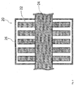
- the structure of the beating unit 20 will be described with reference to FIGS. 2 and 3 .
- the beating unit 20 has a beating member 22 (first beating member), a rotational shaft 24 (first rotational shaft), and a housing 26 (first housing).
- the beating member 22 beats the disposable diaper fragments shredded by the shredding unit 10.
- the beating member 22 has a plate-like shape and beats the disposable diaper fragments with its plate surface.
- the rotational shaft 24 has a substantially cylindrical shape and is provided so as to be rotatable about its central axis.
- the central axis of the rotational shaft 24 extends horizontally.
- FIGS. 2 and 3 show cross sections that are parallel and perpendicular, respectively, to the central axis.
- the above-described beating member 22 is attached to the circumference of the rotational shaft 24.
- a plurality of beating members 22 are provided.
- the beating members 22 are provided at a plurality of positions (five positions in the present embodiment) along the central axis of the rotational shaft 24.
- FIG. 2 the beating members 22 are provided at a plurality of positions (five positions in the present embodiment) along the central axis of the rotational shaft 24.
- a plurality of (eight, in the present embodiment) beating members 22 are radially attached to the circumference of the rotational shaft 24.
- Each beating member 22 is disposed with its thickness direction extending orthogonally to the central axis.
- the outer diameter of the rotational shaft 24 may be between 15 cm and 25 cm inclusive, for example.
- the housing 26 has a substantially cylindrical tubular shape and is provided so as to enclose the beating members 22 and the rotational shaft 24.
- the central axis of the housing 26 coincides with the central axis of rotational shaft 24.
- the housing 26 is configured to accommodate the disposable diaper fragments shredded by the shredding unit 10.
- the inner diameter of the housing 26 may be between 30 cm and 50 cm inclusive, for example.
- the distance from an inner circumferential surface of the housing 26 to a leading end of each beating member 22 may be between 10 mm and 30 mm inclusive, for example.
- the beating unit 20 beats the disposable diaper fragments with the beating members 22, thereby promoting dissociation of the water-absorbent polymer from the plastic. More specifically, in a state in which the disposable diaper fragments shredded by the shredding unit 10 are accommodated in the housing 26, the rotational shaft 24 is rotated. Then, the beating members 22 rotating together with the rotational shaft 24 repeatedly beat the disposable diaper fragments, and the hitting force and the like generated by the beating promote dissociation of the water-absorbent polymer from the plastic. At this time, a portion of the water-absorbent polymer is completely dissociated from the plastic. The water-absorbent polymer that has been separated from the disposable diaper in this manner is discharged to the outside of the beating unit 20 by a discharging means, which is not shown.
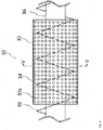
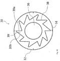
- FIG. 4 is a side view showing the separation unit 30.
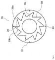
- FIG. 5 is a diagram for explaining the structure of a cross section taken along line V-V in FIG. 4 .
- the separation unit 30 has a drum 32 (first tubular portion).
- the drum 32 has a substantially cylindrical tubular shape and is provided so as to be rotatable about its central axis.
- the central axis of the drum 32 extends horizontally.
- the inner diameter of the drum 32 may be between 30 cm and 50 cm inclusive, for example.
- a large number of holes 32a are formed in the drum 32.
- the holes 32a are formed over substantially the entire drum 32.
- the holes 32a do not allow the plastic contained in the disposable diaper fragments beaten by the beating unit 20 to pass through, but allow the water-absorbent polymer to pass through.
- the diameter of the holes 32a may be between 10 mm and 30 mm inclusive, for example.
- the separation unit 30 rotates the drum 32 in a state in which the disposable diaper fragments beaten by the beating unit 20 are accommodated therein, thereby separating the water-absorbent polymer passing through the holes 32a from the disposable diaper fragments.
- a ridge 34 (first ridge) is formed on an inner circumferential surface of the drum 32.
- the ridge 34 extends in a direction in which the central axis of the drum 32 extends.
- the ridge 34 extends over substantially the entire path from an inlet side (left side of FIG. 4 ) to an outlet side (right side of FIG. 4 ) of the drum 32.
- the ridge 34 has a substantially triangular cross-sectional shape.
- the height of the ridge 34 (length in a radial direction of the drum 32) may be between 5 mm and 20 mm inclusive, for example.
- "p" (p: an integer between 3 and 5 inclusive) ridges 34 are provided.
- a rotating rod 36 and a screw member 38 are provided inside the drum 32.
- the rotating rod 36 has a substantially cylindrical shape and is provided so as to be rotatable about its central axis.
- the central axis of the rotating rod 36 coincides with the central axis of the drum 32.
- the rotating rod 36 rotates independently of the drum 32.
- the outer diameter of the rotating rod 36 may be between 15 cm and 25 cm inclusive, for example.
- the screw member 38 is helically provided around the rotating rod 36.
- the screw member 38 is fixed to the rotating rod 36 and rotates together with the rotating rod 36.
- a plurality of teeth 39 are formed in the screw member 38.
- An end portion of each tooth 39 is constituted by a side 39a and a side 39b in a front view (see FIG. 5 ).
- the side 39a extends in the radial direction of the drum 32 and the rotating rod 36. An inner end (end that is closer to the rotating rod 36) of the side 39a is located at a position spaced apart from the rotating rod 36. Similarly, an outer end (end that is closer to the drum 32) of the side 39a is located at a position spaced apart from the drum 32.
- the distance from the outer end of the side 39a to the inner circumferential surface of the drum 32 may be between 10 mm and 30 mm inclusive, for example. However, this distance is set to be larger than the height of the ridges 34.
- the side 39b connects the outer end of the side 39a to the inner end of the side 39a of the next tooth 39.
- the side 39b is longer than the side 39a.
- the ratio of the length of the side 39b to the length of the side 39a may be between 2 and 2.5 inclusive, for example.
- the rotating rod 36 and the screw member 38 rotate in a left-handed direction (counterclockwise) in FIG. 5 . That is to say, in each tooth 39, the side 39b is located on a forward side with respect to the rotation direction, and the side 39a is located on a rearward side with respect to the rotation direction.
- the rotation direction of the drum 32 described above may be the same as the rotation direction of the rotating rod 36 and the screw member 38 or may be opposite to this rotation direction. In the case where these rotation directions are the same, it is preferable that the rotation speed of the rotating rod 36 and the screw member 38 is greater than the rotation speed of the drum 32.
- the shredding unit 40 shreds the disposable diaper fragments from which the water-absorbent polymer passing through the holes 32a has been separated by the separation unit 30.
- a crusher or a grinder can be used as the shredding unit 40.
- a screen is provided in the shredding unit 40.
- the hole diameter of the screen may be between 10 mm and 50 mm inclusive, for example.
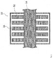
- the structure of the beating unit 50 will be described with reference to FIGS. 6 and 7 .
- the beating unit 50 has a beating member 52 (second beating member), a rotational shaft 54 (second rotational shaft), and a housing 56 (second housing).
- the beating member 52 beats the disposable diaper fragments shredded by the shredding unit 40.
- the beating member 52 has a plate-like shape and beats the disposable diaper fragments with its plate surface.
- the rotational shaft 54 has a substantially cylindrical shape and is provided so as to be rotatable about its central axis.
- the central axis of the rotational shaft 54 extends horizontally.
- FIGS. 6 and 7 show cross sections that are parallel and perpendicular, respectively, to the central axis.
- the above-described beating member 52 is attached to the circumference of the rotational shaft 54.
- a plurality of beating members 52 are provided.
- the beating members 52 are provided at a plurality of positions (five positions in the present embodiment) along the central axis of the rotational shaft 54.
- FIG. 6 the beating members 52 are provided at a plurality of positions (five positions in the present embodiment) along the central axis of the rotational shaft 54.
- a plurality of (eight, in the present embodiment) beating members 52 are radially attached to the circumference of the rotational shaft 54.
- Each beating member 52 is disposed with its thickness direction extending orthogonally to the central axis.
- the outer diameter of the rotational shaft 54 may be between 15 cm and 25 cm inclusive, for example.
- the housing 56 has a substantially cylindrical tubular shape and is provided so as to enclose the beating members 52 and the rotational shaft 54.
- the central axis of the housing 56 coincides with the central axis of rotational shaft 54.
- the disposable diaper fragments shredded by the shredding unit 40 are accommodated in the housing 56.
- the inner diameter of the housing 56 may be between 30 cm and 50 cm inclusive, for example.
- the distance from an inner circumferential surface of the housing 56 to a leading end of each beating member 52 is smaller than the above-described distance from the inner circumferential surface of the housing 26 to the leading end of each beating member 22, and may be between 5 mm and 15 mm inclusive, for example.
- the beating unit 50 beats the disposable diaper fragments with the beating members 52, thereby promoting dissociation of the water-absorbent polymer from the plastic. More specifically, in a state in which the disposable diaper fragments shredded by the shredding unit 40 are accommodated in the housing 56, the rotational shaft 54 is rotated. Then, the beating members 52 rotating together with the rotational shaft 54 repeatedly beat the disposable diaper fragments, and the hitting force and the like generated by the beating promote dissociation of the water-absorbent polymer from the plastic. At this time, a portion of the water-absorbent polymer is completely dissociated from the plastic. The water-absorbent polymer that has been separated from the disposable diaper in this manner is discharged to the outside of the beating unit 50 by a discharging means, which is not shown.
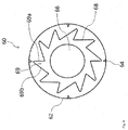
- FIG. 8 is a side view showing the separation unit 60.
- FIG. 9 is a diagram for explaining the structure of a cross section taken along line IX-IX in FIG. 8 .
- the separation unit 60 has a drum 62 (second tubular portion).
- the drum 62 has a substantially cylindrical tubular shape and is provided so as to be rotatable about its central axis.
- the central axis of the drum 62 extends horizontally.
- the inner diameter of the drum 62 may be between 30 cm and 50 cm inclusive, for example.
- a large number of holes 62a are formed in the drum 62.
- the holes 62a are formed over substantially the entire drum 62.
- the holes 62a do not allow the plastic contained in the disposable diaper fragments beaten by the beating unit 50 to pass through, but allow the water-absorbent polymer to pass through.
- the diameter of the holes 62a may be between 5 mm and 10 mm inclusive, for example.
- the separation unit 60 rotates the drum 62 in a state in which the disposable diaper fragments beaten by the beating unit 50 are accommodated therein, thereby separating the water-absorbent polymer passing through the holes 62a from the disposable diaper fragments.
- a ridge 64 (second ridge) is formed on an inner circumferential surface of the drum 62.
- the ridge 64 extends in a direction in which the central axis of the drum 62 extends.
- the ridge 64 extends over substantially the entire path from an inlet side (left side of FIG. 8 ) to an outlet side (right side of FIG. 8 ) of the drum 62.
- the ridge 64 has a substantially triangular cross-sectional shape.
- the height (length in the radial direction of the drum 62) of the ridge 64 is smaller than the height of the above-described ridges 34 and may be between 3 mm and 10 mm inclusive, for example.
- "q" (q: an integer between 3 and 5 inclusive) ridges 64 are provided.
- a rotating rod 66 and a screw member 68 are provided inside the drum 62.
- the rotating rod 66 has a substantially cylindrical shape and is provided so as to be rotatable about its central axis.
- the central axis of the rotating rod 66 coincides with the central axis of the drum 62.
- the rotating rod 66 rotates independently of the drum 62.
- the outer diameter of the rotating rod 66 may be between 15 cm and 25 cm inclusive, for example.
- the screw member 68 is helically provided around the rotating rod 66.
- the screw member 68 is fixed to the rotating rod 66 and rotates together with the rotating rod 66.
- a plurality of teeth 69 are formed in the screw member 68.
- An end portion of each tooth 69 is constituted by a side 69a and a side 69b in a front view (see FIG. 9 ).
- the side 69a extends in the radial direction of the drum 62 and the rotating rod 66.
- An inner end (end that is closer to the rotating rod 66) of the side 69a is located at a position spaced apart from the rotating rod 66.
- an outer end (end that is closer to the drum 62) of the side 69a is located at a position spaced apart from the drum 62.
- the distance from the outer end of the side 69a to the inner circumferential surface of the drum 62 is smaller than the above-described distance from the outer end of the side 39a to the inner circumferential surface of the drum 32 and may be between 5 mm and 15 mm inclusive, for example.
- the distance from the outer end of the side 69a to the inner circumferential surface of the drum 62 is set to be larger than the height of the ridges 64.
- the side 69b connects the outer end of the side 69a to the inner end of the side 69a of the next tooth 69.
- the side 69b is longer than the side 69a.
- the ratio of the length of the side 69b to the length of the side 69a may be between 2 and 2.5 inclusive, for example.
- the rotating rod 66 and the screw member 68 rotate in a left-handed direction (counterclockwise) in FIG. 9 . That is to say, in each tooth 69, the side 69b is located on the forward side with respect to the rotation direction, and the side 69a is located on the rearward side with respect to the rotation direction.
- the rotation direction of the drum 62 described above may be the same as the rotation direction of the rotating rod 66 and the screw member 68 or may be opposite to this rotation direction. In the case where these rotation directions are the same, it is preferable that the rotation speed of the rotating rod 66 and the screw member 68 is greater than the rotation speed of the drum 62.
- a disposable diaper which is a processing target, is first shredded by the shredding unit 10 into fragments.
- the disposable diaper fragments shredded by the shredding unit 10 are transferred to the beating unit 20.
- a belt conveyor or a screw conveyor can be used for the transfer.
- the disposable diaper fragments transferred to the beating unit 20 are accommodated in the housing 26 and, in this state, beaten by the beating members 22 rotating together with the rotational shaft 24. Thus, dissociation of the water-absorbent polymer from the plastic is promoted.
- the disposable diaper fragments beaten by the beating unit 20 are transferred to the separation unit 30.
- the disposable diaper fragments transferred to the separation unit 30 are propelled from the inlet side (left side of FIG. 4 ) to the outlet side (right side of FIG. 4 ) of the drum 32 by the rotating screw member 38. Meanwhile, due to the centrifugal force and the like generated by the rotation of the drum 32, the water-absorbent polymer dissociated from the plastic is discharged to the outside of the drum 32 through the holes 32a. Thus, a portion of the water-absorbent polymer is separated from the disposable diaper fragments. It should be noted that in the case where the processing target is a disposable diaper as in the present embodiment, fluff pulp is also separated together with the water-absorbent polymer.
- the disposable diaper fragments after separation by the separation unit 30 are transferred to the shredding unit 40 and are further shredded.
- the disposable diaper fragments shredded by the shredding unit 40 are transferred to the beating unit 50.
- the disposable diaper fragments transferred to the beating unit 50 are accommodated in the housing 56 and, in this state, beaten by the beating members 52 rotating together with the rotational shaft 54. Thus, dissociation of the water-absorbent polymer from the plastic is promoted.
- the disposable diaper fragments beaten by the beating unit 50 are transferred to the separation unit 60.
- the disposable diaper fragments transferred to the separation unit 60 are propelled from the inlet side (left side of FIG. 8 ) to the outlet side (right side of FIG. 8 ) of the drum 62 by the rotating screw member 68. Meanwhile, due to the centrifugal force and the like generated by the rotation of the drum 62, the water-absorbent polymer dissociated from the plastic is discharged to the outside of the drum 62 through the holes 62a. Thus, the remaining water-absorbent polymer is separated from the disposable diaper fragments.
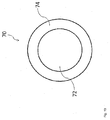
- FIG. 10 schematically shows an embodiment of a water absorption material according to the present invention.
- a water absorption material 70 is a water absorption material that absorbs a liquid, and includes a granular core portion 72 (granulated matter) and a coating layer portion 74.
- the water absorption material 70 may be, for example, an excrement disposal material for pets such as cats and dogs.
- the granular core portion 72 is is formed to be granular in form. Examples of the shape of the granular core portion 72 include a sphere, an ellipse, and a cylinder.
- the granular core portion 72 has the function of absorbing and retaining a liquid such as urine.
- the plastic obtained from a disposable diaper using the above-described separation device 1 i.e., plastic from which the water-absorbent polymer and the fluff pulp have been separated
- the granular core portion 72 may be composed only of plastic or may be composed so as to also contain a material other than plastic.
- the granular core portion 72 is coated with the coating layer portion 74.
- the entire surface of the granular core portion 72 may be coated with the coating layer portion 74, or only a portion of the surface of the granular core portion 72 may be coated with the coating layer portion 74.
- the coating layer portion 74 has the function of causing members of the water absorption material 70 that have absorbed a liquid such as urine to adhere to each other and to form clumps.
- paper powder and a water-absorbent polymer can be used as the materials (coating material) for the coating layer portion 74.
- This manufacturing method includes a separation step, a granulation step, a coating step, a sizing step, and a drying step.
- the separation step the plastic and the water-absorbent polymer contained in the disposable diaper are separated using the separation device 1.
- a material to be granulated containing the plastic obtained in the separation step is granulated.
- an extrusion granulator can be used for granulation.
- water may be added to the material to be granulated prior to granulation, if necessary.
- the granular core portion 72 is obtained.
- a coating material is deposited on the surface of the granular core portion 72 formed in the granulation step.
- the coating material contains the water-absorbent polymer obtained in the separation step.
- the deposition of the coating material can be performed through sprinkling or spraying using a coater, for example.
- the coating layer portion 74 is obtained.
- the water absorption material manufactured through the prior steps is caused to pass through a sieve having a predetermined mesh size. Thus, only a portion of the water absorption material that satisfies a predetermined standard is extracted.
- the water absorption material extracted in the previous step is dried in a dryer.
- the percentage of moisture content in the granular core portion 72 is adjusted as appropriate through drying.
- the transition of the moisture content in the granular core portion 72 to the coating layer portion 74 and a resultant decrease in water absorption capacity can be prevented, and also the occurrence of mold and the like during storage of the water absorption material 70 can be prevented.
- beating by the beating unit 20 is performed prior to separation by the separation unit 30.
- the beating promotes the dissociation of the water-absorbent polymer from the plastic. That is to say, beating by the beating unit 20 dissociates a portion of the water-absorbent polymer from the plastic, and thus reduces the amount of water-absorbent polymer adhering to the plastic. This contributes to a reduction in the processing load on the separation unit 30.
- the other portion of the water-absorbent polymer that has not been dissociated from the plastic in the beating unit 20 is also in an easy-to-dissociate state, because the adhesion to the plastic is reduced due to the hitting force and the like generated by the beating.
- the separation unit 30 the water-absorbent polymer is easily separated from the disposable diaper fragments, and therefore the separation efficiency is improved.
- the separation device 1 having excellent separation efficiency as described above is particularly useful in cases where the processing target is a hygiene product such as a disposable diaper as in the present embodiment.
- the reason for this is that, in such a hygiene product, which has a structure in which a particulate water-absorbent polymer adheres to a sheet-like plastic, it is difficult to separate the water-absorbent polymer, and as such a sufficient separation efficiency has not been achieved by conventional separation devices.
- the beating members 22 are attached to the circumference of the rotational shaft 24. With this configuration, the beating members 22 can be rotated together with the rotational shaft 24. Thus, beating of the disposable diaper fragments with the beating members 22 can be efficiently performed.
- the plurality of beating members 22 radially attached to the circumference of the rotational shaft 24 are provided in the beating unit 20.
- the rotational shaft 24 makes one rotation, the disposable diaper fragments are beaten with the plurality of beating members 22, and thus beating of the disposable diaper fragments by the beating members 22 can be performed even more efficiently.
- the beating members 22 each have a plate-like shape and are configured to beat the disposable diaper fragments with their plate surfaces. A strong hitting force can be applied to the disposable diaper fragments by beating the disposable diaper with the plate surfaces of the beating members 22 in this manner.
- the housing 26 is provided so as to enclose the beating members 22 and the rotational shaft 24. Therefore, a portion of the disposable diaper fragments beaten by the beating members 22 is rubbed against the inner circumferential surface of the housing 26.
- the beating unit 20 not only the hitting force that acts on the disposable diaper fragments during beating by the beating members 22, but also a frictional force that acts on the disposable diaper fragments while they are being rubbed against the inner circumferential surface of the housing 26 contributes to the dissociation of the water-absorbent polymer from the plastic.
- a portion of the disposable diaper fragments is flung by the beating members 22 and strikes the inner circumferential surface and the like of the housing 26. The impact force that acts on the disposable diaper fragments at this time also contributes to the dissociation of the water-absorbent polymer from the plastic.
- the drum 32 is provided with the ridges 34. If the ridges 34 are not provided, the disposable diaper fragments tend to collect in a lower portion of the drum 32 due to the effect of gravity. In contrast, in the present embodiment, the disposable diaper fragments in the drum 32 are scooped up by the ridges 34 and thus easily reach an upper portion of the drum 32. This scooping effect allows the disposable diaper fragments to be distributed over a wide range of the inner circumferential surface of the drum 32, so that separation by the separation unit 30 is promoted. Moreover, dissociation of the water-absorbent polymer from the plastic is promoted by the impact of the disposable diaper fragments when falling down from the upper portion of the drum 32.
- the ridges 34 become obstacles when the disposable diaper fragments are propelled by the screw member 38, and thus the time for which the disposable diaper fragments stay in the drum 32 is prolonged. Thus, a larger amount of water-absorbent polymer can be separated from the disposable diaper fragments.
- the screw member 38 is provided inside the drum 32.
- a portion of the disposable diaper fragments in the drum 32 is rubbed against the inner circumferential surface of the drum 32 by the screw member 38.
- the frictional force at this time also promotes the dissociation of the water-absorbent polymer from the plastic.
- the ridges 34 are provided, the disposable diaper fragments may be rubbed against the inner circumferential surface of the drum 32 in a state in which the disposable diaper fragments are caught on the ridges 34. In that case, forces are focused, so that the frictional force that is applied to the disposable diaper fragments increases, and accordingly dissociation of the water-absorbent polymer from the plastic is promoted even more.
- the screw member 38 rotates with the side 39b that forms an obtuse angle with the rotation direction (direction of the tangent to the rotating rod 36), rather than the side 39a that forms an approximately right angle with the rotation direction, being located on the forward side (see FIG. 5 ).
- the disposable diaper fragments can be prevented from being excessively caught on the teeth 39 of the screw member 38.
- shredding by the shredding unit 10 after shredding by the shredding unit 10, beating by the beating unit 20, and separation by the separation unit 30 have been performed, shredding by the shredding unit 40, beating by the beating unit 50, and separation by the separation unit 60 are performed. Since shredding, beating, and separation are performed twice in this manner, the separation efficiency is improved even more.
- the beating members 52 are attached to the circumference of the rotational shaft 54. With this configuration, the beating members 52 can be rotated together with the rotational shaft 54. Thus, beating of the disposable diaper fragments by the beating members 52 can be efficiently performed.
- the plurality of beating members 52 radially attached to the circumference of the rotational shaft 54 are provided in the beating unit 50.
- the rotational shaft 54 makes one rotation, the disposable diaper fragments are beaten with the plurality of beating members 52, and thus beating of the disposable diaper fragments by the beating members 52 can be performed even more efficiently.
- the beating members 52 each have a plate-like shape and are configured to beat the disposable diaper fragments with their plate surfaces. A strong hitting force can be applied to the disposable diaper fragments by beating the disposable diaper fragments with the plate surfaces of the beating members 52 in this manner.
- the housing 56 is provided so as to enclose the beating members 52 and the rotational shaft 54. Therefore, a portion of the disposable diaper fragments beaten by the beating members 52 is rubbed against the inner circumferential surface of the housing 56.
- the beating unit 50 not only the hitting force that acts on the disposable diaper fragments during beating by the beating members 22, but also a frictional force that acts on the disposable diaper fragments while they are being rubbed against the inner circumferential surface of the housing 56 contributes to the dissociation of the water-absorbent polymer from the plastic.
- a portion of the disposable diaper fragments is flung by the beating members 52 and strikes the inner circumferential surface and the like of the housing 56. The impact force that acts on the disposable diaper fragments at this time also contributes to the dissociation of the water-absorbent polymer from the plastic.
- the distance from the inner circumferential surface of the housing 56 to the leading end of each beating member 52 is smaller than the distance from the inner circumferential surface of the housing 26 to the leading end of each beating member 22. That is to say, in the beating unit 20, in which relatively large disposable diaper fragments are processed, the distance between the housing 26 and each beating member 22 is relatively large, whereas in the beating unit 50, in which relatively small disposable diaper fragments are processed, the distance between the housing 56 and each beating member 52 is relatively small. Setting the above-described distances in accordance with the size of the processing target in this manner makes it possible to apply an appropriate frictional force to the processing target in either beating unit. However, it is not absolutely necessary to set the distance from the inner circumferential surface of the housing 56 to the leading end of each beating member 52 to be smaller than the distance from the inner circumferential surface of the housing 26 to the leading end of each beating member 22.
- the drum 62 is provided with the ridges 64. If the ridges 64 are not provided, the disposable diaper fragments tend to collect in a lower portion of the drum 62 due to the effect of gravity. In contrast, in the present embodiment, the disposable diaper fragments in the drum 62 are scooped up by the ridges 64 and thus easily reach an upper portion of the drum 62. This scooping effect allows the disposable diaper fragments to be distributed over a wide range of the inner circumferential surface of the drum 62, so that separation by the separation unit 60 is promoted. Moreover, dissociation of the water-absorbent polymer from the plastic is promoted by the impact of the disposable diaper fragments when falling down from the upper portion of the drum 62.
- the ridges 64 become obstacles when the disposable diaper fragments are propelled by the screw member 68, and thus the time for which the disposable diaper fragments stay in the drum 62 is prolonged. Thus, a larger amount of water-absorbent polymer can be separated from the disposable diaper fragments.
- the height of the ridges 64 is smaller than the height of the ridges 34. That is to say, in the separation unit 30, in which relatively large disposable diaper fragments are processed, the height of the ridges 34 is relatively large, whereas in the separation unit 60, in which relatively small disposable diaper fragments are processed, the height of the ridges 64 is relatively small. Setting the height of the ridges in accordance with the size of the processing target makes it possible to achieve a sufficient effect of the ridges scooping up the processing target in either separation unit. However, it is not absolutely necessary to set the height of the ridges 64 to be smaller than the height of the ridges 34.
- the screw member 68 is provided inside the drum 62.
- a portion of the disposable diaper fragments in the drum 62 is rubbed against the inner circumferential surface of the drum 62 by the screw member 68.
- the frictional force at this time also promotes the dissociation of the water-absorbent polymer from the plastic.
- the ridges 64 are provided, the disposable diaper fragments may be rubbed against the inner circumferential surface of the drum 62 in a state in which the disposable diaper fragments are caught on the ridges 64. In that case, forces are focused, so that the frictional force that is applied to the disposable diaper fragments increases, and accordingly dissociation of the water-absorbent polymer from the plastic is promoted even more.
- the distance from the outer end of the side 69a to the inner circumferential surface of the drum 62 is smaller than the distance from the outer end of the side 39a to the inner circumferential surface of the drum 32. That is to say, in the separation unit 30, in which relatively large disposable diaper fragments are processed, the distance from the outer end of the side 39a to the inner circumferential surface of the drum 32 is relatively large, whereas in the separation unit 60, in which relatively small disposable diaper fragments are processed, the distance from the outer end of the side 69a to the inner circumferential surface of the drum 62 is relatively small. Setting the above-described distance in accordance with the size of the processing target in this manner makes it possible to apply an appropriate frictional force to the processing target in either separation unit. However, it is not absolutely necessary to set the distance from the outer end of the side 69a to the inner circumferential surface of the drum 62 to be smaller than the distance from the outer end of the side 39a to the inner circumferential surface of the drum 32.
- the screw member 68 rotates with the side 69b that forms an obtuse angle with the rotation direction (direction of the tangent to the rotating rod 66), rather than the side 69a that forms an approximately right angle with the rotation direction, being located on the forward side (see FIG. 9 ).
- the disposable diaper fragments can be prevented from being excessively caught on the teeth 69 of the screw member 68.
- the plastic obtained in the separation step is used as the material for the granular core portion 72.
- the cost of procuring the plastic can be reduced by effectively using defective or discarded disposable diapers.
- the separation device 1 having excellent separation efficiency as described above is used, and thus, the ratio of impurities (water-absorbent polymer and fluff pulp that have not been separated from disposable diaper fragments) contained in the granular core portion 72 can be reduced to a low level.
- the cost of procuring the water-absorbent polymer can be reduced by effectively using defective or discarded disposable diapers.
- the various numerical values shown in the foregoing embodiments by way of example can be set as appropriate in accordance with] the size and the like of the processing target.
- the hole diameter of the screen of the shredding unit 10 can be set between 30 mm and 50 mm inclusive
- the hole diameter of the screen of the shredding unit 40 can be set between 10 mm and 30 mm inclusive.
- an opening 22a may also formed in the plate surface of each beating member 22 as shown in FIG. 11 .
- a plurality of openings 22a are formed. These openings 22a are provided in order to reduce air resistance while the beating members 22 rotate. That is to say, while the beating members 22 are rotating, air passes through the openings 22a, and therefore, the air resistance acting on the beating members 22 can be reduced.
- power consumption of the beating unit 20 can be reduced, and wind pressure exerted on the processing target from the beating members 22 can be reduced to a low level. If high wind pressure is exerted on the processing target, the processing target is moved away from the plate surfaces of the beating members 22 before the processing target is beaten.
- the openings 22a may also be formed by forming substantially the whole or a part of each beating member 22 in a mesh form. That is to say, in this case, the meshes of each beating member 22 correspond to the openings 22a.
- a similar opening 52a (second opening) may also be formed in the plate surface of each beating member 52 as shown in FIG. 12 .
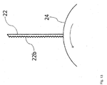
- protrusions and depressions may also be formed on the plate surface of each beating member 22 as shown in FIG. 13 . That is to say, the plate surfaces (surfaces with which the processing target is beaten) of the beating members 22 are uneven surfaces 22b. As indicated by the arrow in this diagram, the beating members 22 and the rotational shaft 24 rotate in the left-handed direction (counterclockwise). Beating the processing target with these uneven surfaces 22b makes it possible to exert a stronger impact on the processing target than in the case where the processing target is beaten with flat surfaces. Similar protrusions and depressions (uneven surface 52b) may also be formed in the plate surface of each beating member 52 as shown in FIG. 14 .
- the drum 32 has a cylindrical tubular shape.
- the drum 32 has a tapered shape. The same applies to the drum 62.
- the holes 32a are formed over substantially the entire drum 32 .
- the holes 32a are formed in only a portion of the drum 32.
- the holes 32a are formed by forming substantially the whole or a portion of the drum 32 in a mesh form. That is to say, in this case, the meshes of the drum 32 correspond to the holes 32a. The same applies to the holes 62a.
- the ridges 34 extend over the entire path from the inlet side to the outlet side of the drum 32 .
- the ridges 34 extend in only a portion of the path from the inlet side to the outlet side of the drum 32. The same applies to the ridges 64.
- the ridges 34 having a substantially triangular cross-sectional shape have been described as an example. However, it is also possible that the ridges 34 have a flat plate-like shape as shown in FIG. 15 . The same applies to the ridges 64.
- ridges 34 are provided on the inner circumferential surface of the drum 32 .
- the number of ridges 34 can be set at any number greater than or equal to 1. The same applies to the ridges 64.
- the water absorption material 70 having a multi-layer structure composed of the granular core portion 72 and the coating layer portion 74 has been described as an example.
- the provision of the coating layer portion 74 is not necessarily required. That is to say, the water absorption material 70 may also have a single layer structure composed only of the granular core portion 72.
Landscapes
- Chemical & Material Sciences (AREA)
- Engineering & Computer Science (AREA)
- Chemical Kinetics & Catalysis (AREA)
- Analytical Chemistry (AREA)
- Organic Chemistry (AREA)
- Environmental & Geological Engineering (AREA)
- Mechanical Engineering (AREA)
- Processing Of Solid Wastes (AREA)
- Combined Means For Separation Of Solids (AREA)
- Separation, Recovery Or Treatment Of Waste Materials Containing Plastics (AREA)
- Glanulating (AREA)
- Solid-Sorbent Or Filter-Aiding Compositions (AREA)
- Absorbent Articles And Supports Therefor (AREA)
- Crushing And Pulverization Processes (AREA)
Applications Claiming Priority (2)
| Application Number | Priority Date | Filing Date | Title |
|---|---|---|---|
| JP2015009945A JP6317265B2 (ja) | 2015-01-22 | 2015-01-22 | 分離装置、及び吸水処理材の製造方法 |
| PCT/JP2015/067591 WO2016117145A1 (ja) | 2015-01-22 | 2015-06-18 | 分離装置、及び吸水処理材の製造方法 |
Publications (2)
| Publication Number | Publication Date |
|---|---|
| EP3248694A1 true EP3248694A1 (de) | 2017-11-29 |
| EP3248694A4 EP3248694A4 (de) | 2018-05-23 |
Family
ID=56416709
Family Applications (1)
| Application Number | Title | Priority Date | Filing Date |
|---|---|---|---|
| EP15878835.6A Withdrawn EP3248694A4 (de) | 2015-01-22 | 2015-06-18 | Trennvorrichtung und verfahren zur herstellung von wasserabsorbierendem material |
Country Status (5)
| Country | Link |
|---|---|
| US (1) | US10124371B2 (de) |
| EP (1) | EP3248694A4 (de) |
| JP (1) | JP6317265B2 (de) |
| CN (1) | CN107107116B (de) |
| WO (1) | WO2016117145A1 (de) |
Families Citing this family (12)
| Publication number | Priority date | Publication date | Assignee | Title |
|---|---|---|---|---|
| JP6465917B2 (ja) | 2017-03-31 | 2019-02-06 | ユニ・チャーム株式会社 | 使用済み吸収性物品から構成部材を回収する方法 |
| JP6517408B1 (ja) * | 2018-06-21 | 2019-05-22 | 株式会社大貴 | 吸水処理材の製造方法 |
| JP7228992B2 (ja) * | 2018-11-13 | 2023-02-27 | ユニ・チャーム株式会社 | 使用済み吸収性物品から構成部材を回収する方法 |
| JP6993996B2 (ja) * | 2019-02-25 | 2022-01-14 | パナソニック株式会社 | 使用済み紙おむつ処理装置 |
| US20230038184A1 (en) * | 2019-12-24 | 2023-02-09 | Lixil Corporation | Crushing device and waste treatment device |
| JP7426713B2 (ja) * | 2020-07-10 | 2024-02-02 | 株式会社辰巳エヤーエンジニアリング | 吸水材回収システム及び吸水材回収方法 |
| CN112222040B (zh) * | 2020-10-17 | 2022-01-11 | 吉林福康药业股份有限公司 | 一种基于自动控制的胶囊机用毛刷高效清理机构 |
| JP7630252B2 (ja) * | 2020-10-20 | 2025-02-17 | ユニ・チャーム株式会社 | 使用済み吸収性物品を含む使用済み不織布製品からプラスチック材料を回収する方法 |
| CN112842696A (zh) * | 2021-02-26 | 2021-05-28 | 广东宜柔健康产品有限公司 | 一种成人纸尿裤生产方法 |
| JP7696102B2 (ja) * | 2021-07-16 | 2025-06-20 | パナソニックIpマネジメント株式会社 | 使用済み紙おむつ処理装置 |
| CN118434932A (zh) * | 2021-09-17 | 2024-08-02 | 益钧环保科技股份有限公司 | 纤维原料处理系统及其运作方法 |
| CN118434931A (zh) * | 2021-09-17 | 2024-08-02 | 益钧环保科技股份有限公司 | 吸收性物品快速分解系统及其运作方法 |
Family Cites Families (41)
| Publication number | Priority date | Publication date | Assignee | Title |
|---|---|---|---|---|
| US3756406A (en) * | 1970-07-14 | 1973-09-04 | Us Agriculture | Grain cleaner |
| US3931937A (en) * | 1972-06-30 | 1976-01-13 | Pennsylvania Crusher Corporation | Breaker/crusher |
| US3973735A (en) * | 1974-04-01 | 1976-08-10 | Keishin Matsumoto, President of Agency of Industrial Science and Technology | Apparatus for pulverizing and sorting municipal waste |
| ATE27625T1 (de) * | 1982-04-19 | 1987-06-15 | Bert Steffens | Verfahren und vorrichtung zur trennung von zellstofflocken von deren umhuellungen von zellstoff-hygieneartikeln. |
| IT1218840B (it) * | 1984-01-10 | 1990-04-24 | Fibropolimeri Srl | Lavatrice per il lavaggio o separazione del film di plastica dalle fibre di carta o cellulosa e procedimento relativo |
| US5437418A (en) * | 1987-01-20 | 1995-08-01 | Weyerhaeuser Company | Apparatus for crosslinking individualized cellulose fibers |
| JPS63209761A (ja) * | 1987-02-26 | 1988-08-31 | 栗本商事株式会社 | 衝撃式破砕機の打撃板 |
| DE69133244T2 (de) * | 1990-10-29 | 2004-05-06 | Knowaste L.L.C. | Behandlung eines superabsorbierenden Polymers |
| US5431347A (en) * | 1991-12-02 | 1995-07-11 | Hitachi, Ltd. | System and method for disposing waste |
| US5429311A (en) * | 1992-05-22 | 1995-07-04 | Dia Tec Recycling Technologies, Ltd. | Process of recycling of disposable diapers and the machine components thereof |
| US5292075A (en) * | 1992-05-29 | 1994-03-08 | Knobbe, Martens, Olson & Bear | Disposable diaper recycling process |
| DE4331782C1 (de) * | 1993-09-18 | 1994-08-18 | Reimelt Dietrich Kg | Siebeinrichtung |
| JP3566760B2 (ja) * | 1994-10-20 | 2004-09-15 | 林太郎 薦田 | 紙おむつ等の不良品から有価物を分離回収する分離装置および分離方法 |
| US5618003A (en) * | 1995-03-09 | 1997-04-08 | Bot Chan, Inc. | Process and apparatus for reclaiming the components of used disposable sanitary articles |
| JP2631359B2 (ja) * | 1995-04-12 | 1997-07-16 | 西村産業有限会社 | 廃棄されているほたて貝の外套膜を食品に有効に利用する中腸腺の除去方法と装置 |
| DE19616623B4 (de) * | 1996-04-25 | 2004-12-23 | Der Grüne Punkt - Duales System Deutschland Ag | Vorrichtung zur Trennung von zähelastischen Materialien wie Kunststoffen und von unter mechanischer Beanspruchung zerfasernden Stoffen wie Papier |
| SE506804C2 (sv) * | 1996-06-24 | 1998-02-16 | Cellwood Machinery Ab | Sätt och anläggning för återvinning av olika komponenter i flerskiktsmaterial |
| JP2879770B2 (ja) * | 1996-12-27 | 1999-04-05 | 里之 高林 | 害虫叩き兼用うちわ |
| JP2002143702A (ja) * | 2000-11-09 | 2002-05-21 | Yonehara Giken Kk | コンクリート等の破砕処理方法及び装置 |
| JP3666800B2 (ja) * | 2000-12-18 | 2005-06-29 | 鹿島建設株式会社 | 生ごみ様廃棄物の異物分離装置 |
| DE10135398A1 (de) * | 2001-07-25 | 2003-02-20 | Recover System Recycling Gmbh | Verfahren und Vorrichtung zum Klassieren von Wertstoff mit mindestens einer Faserfraktion |
| CA2537694C (en) * | 2003-09-03 | 2012-08-28 | United Resource Recovery Corporation | Dry separation of contaminants from polyester materials |
| US7004414B2 (en) * | 2004-02-04 | 2006-02-28 | Mei Chi Chen | Blade for food processors |
| JP2006212376A (ja) * | 2005-02-02 | 2006-08-17 | Haruyoshi Kitahara | 卓球ラケット |
| JP4810852B2 (ja) * | 2005-03-28 | 2011-11-09 | 富士電機株式会社 | 粉砕分別処理装置及びその運転方法 |
| JP3118406U (ja) * | 2005-11-08 | 2006-01-26 | 光江 井上 | 蝿たたき装置 |
| JP4755564B2 (ja) * | 2006-10-06 | 2011-08-24 | 株式会社 ガラステクノシナジー | 破砕された合わせガラスからガラス片と中間膜とを分離する装置 |
| JP2008302270A (ja) * | 2007-06-06 | 2008-12-18 | Kanai Hiroaki | 塗装付着強さテスト器および同テスト器による塗装付着強さのテスト方法 |
| EP2430086B1 (de) * | 2009-05-16 | 2015-08-26 | Knowaste International LLC | Verfahren zur trennung und aufbereitung von produkten mit superabsorbierenden polymeren |
| JP5686579B2 (ja) * | 2010-11-16 | 2015-03-18 | 株式会社御池鐵工所 | 破砕分別装置及び破砕分別方法 |
| JP5670707B2 (ja) * | 2010-11-17 | 2015-02-18 | 株式会社御池鐵工所 | 廃棄物の破砕分別装置 |
| JP5764558B2 (ja) * | 2011-02-28 | 2015-08-19 | 株式会社大貴 | 吸水処理材 |
| US8827545B2 (en) * | 2012-08-28 | 2014-09-09 | Sanyasi R. Kalidindi | Apparatus for alternately sifting and blending powders in the same operation |
| JP5948221B2 (ja) * | 2012-11-02 | 2016-07-06 | ユニ・チャーム株式会社 | 吸収性物品に係る材料の分離装置、及び分離方法 |
| JP5934631B2 (ja) * | 2012-11-02 | 2016-06-15 | ユニ・チャーム株式会社 | 吸収性物品に係る材料の分離装置 |
| CN103112102B (zh) * | 2013-01-31 | 2015-09-02 | 冯愚斌 | 废塑料清洗用的多功能磨蹭分离装置 |
| JP6170997B2 (ja) * | 2013-02-15 | 2017-07-26 | 株式会社大貴 | 分離装置 |
| JP6170996B2 (ja) * | 2013-02-15 | 2017-07-26 | 株式会社大貴 | 分離装置及び分離方法 |
| KR20150130340A (ko) * | 2013-02-28 | 2015-11-23 | 모비에어 피티이. 엘티디. | 위생 제조에 연결되거나 오프-라인 위치에서 작동하는 선택적 파쇄, 체질, 및/또는 분리 장치 |
| EP2995372A4 (de) * | 2013-05-10 | 2017-01-04 | Daiki Co. Ltd. | Wasserabsorbierendes bearbeitungsmaterial und herstellungsverfahren dafür |
| JP6173365B2 (ja) * | 2015-02-03 | 2017-08-02 | 株式会社大貴 | 分離装置、及び吸水処理材の製造方法 |
-
2015
- 2015-01-22 JP JP2015009945A patent/JP6317265B2/ja active Active
- 2015-06-18 EP EP15878835.6A patent/EP3248694A4/de not_active Withdrawn
- 2015-06-18 WO PCT/JP2015/067591 patent/WO2016117145A1/ja not_active Ceased
- 2015-06-18 CN CN201580071424.XA patent/CN107107116B/zh active Active
-
2017
- 2017-05-09 US US15/590,445 patent/US10124371B2/en active Active
Also Published As
| Publication number | Publication date |
|---|---|
| WO2016117145A1 (ja) | 2016-07-28 |
| CN107107116B (zh) | 2020-05-05 |
| EP3248694A4 (de) | 2018-05-23 |
| JP2016131956A (ja) | 2016-07-25 |
| CN107107116A (zh) | 2017-08-29 |
| US20170239687A1 (en) | 2017-08-24 |
| JP6317265B2 (ja) | 2018-04-25 |
| US10124371B2 (en) | 2018-11-13 |
Similar Documents
| Publication | Publication Date | Title |
|---|---|---|
| US10124371B2 (en) | Separation device and method for manufacturing water absorption material | |
| US9393546B2 (en) | Water absorbing material and manufacturing method thereof | |
| US10071362B2 (en) | Water absorbing material and manufacturing method thereof | |
| US10549454B2 (en) | Separation device and method for manufacturing water absorption material | |
| US20150283732A1 (en) | Separation device and separation method | |
| US10414070B2 (en) | Separation device | |
| US9776166B2 (en) | Manufacturing method of water absorbing material | |
| US9469050B2 (en) | Separation device | |
| EP3050619A1 (de) | Material für wasserabsorption sowie verfahren zur herstellung davon | |
| JP6173363B2 (ja) | 分離装置、及び吸水処理材の製造方法 | |
| HK1236884A1 (en) | Separating apparatus and method for manufacturing water absorption material | |
| HK1236884B (zh) | 分离装置以及吸水处理材的制造方法 | |
| HK1236883A1 (en) | Separation device, and method for producing water absorbability-imparted material |
Legal Events
| Date | Code | Title | Description |
|---|---|---|---|
| PUAI | Public reference made under article 153(3) epc to a published international application that has entered the european phase |
Free format text: ORIGINAL CODE: 0009012 |
|
| 17P | Request for examination filed |
Effective date: 20170524 |
|
| AK | Designated contracting states |
Kind code of ref document: A1 Designated state(s): AL AT BE BG CH CY CZ DE DK EE ES FI FR GB GR HR HU IE IS IT LI LT LU LV MC MK MT NL NO PL PT RO RS SE SI SK SM TR |
|
| AX | Request for extension of the european patent |
Extension state: BA ME |
|
| DAV | Request for validation of the european patent (deleted) | ||
| DAX | Request for extension of the european patent (deleted) | ||
| A4 | Supplementary search report drawn up and despatched |
Effective date: 20180423 |
|
| RIC1 | Information provided on ipc code assigned before grant |
Ipc: B07B 1/22 20060101AFI20180417BHEP Ipc: B01J 20/26 20060101ALN20180417BHEP Ipc: B29B 17/02 20060101ALI20180417BHEP Ipc: B03B 9/06 20060101ALN20180417BHEP Ipc: B07B 1/20 20060101ALI20180417BHEP Ipc: B29B 17/04 20060101ALI20180417BHEP Ipc: B09B 3/00 20060101ALI20180417BHEP Ipc: B01J 20/32 20060101ALN20180417BHEP Ipc: B01J 20/30 20060101ALN20180417BHEP Ipc: B29L 31/48 20060101ALN20180417BHEP Ipc: B09B 5/00 20060101ALI20180417BHEP Ipc: B07B 1/24 20060101ALI20180417BHEP |
|
| STAA | Information on the status of an ep patent application or granted ep patent |
Free format text: STATUS: THE APPLICATION HAS BEEN WITHDRAWN |
|
| 18W | Application withdrawn |
Effective date: 20190704 |