EP3248740B1 - Système de robot industriel sans barrière - Google Patents
Système de robot industriel sans barrière Download PDFInfo
- Publication number
- EP3248740B1 EP3248740B1 EP17169710.5A EP17169710A EP3248740B1 EP 3248740 B1 EP3248740 B1 EP 3248740B1 EP 17169710 A EP17169710 A EP 17169710A EP 3248740 B1 EP3248740 B1 EP 3248740B1
- Authority
- EP
- European Patent Office
- Prior art keywords
- robot
- sensors
- platform
- extended position
- robot system
- Prior art date
- Legal status (The legal status is an assumption and is not a legal conclusion. Google has not performed a legal analysis and makes no representation as to the accuracy of the status listed.)
- Active
Links
Images

Classifications
-
- B—PERFORMING OPERATIONS; TRANSPORTING
- B25—HAND TOOLS; PORTABLE POWER-DRIVEN TOOLS; MANIPULATORS
- B25J—MANIPULATORS; CHAMBERS PROVIDED WITH MANIPULATION DEVICES
- B25J9/00—Program-controlled manipulators
- B25J9/16—Program controls
- B25J9/1674—Program controls characterised by safety, monitoring, diagnostic
- B25J9/1676—Avoiding collision or forbidden zones
-
- B—PERFORMING OPERATIONS; TRANSPORTING
- B25—HAND TOOLS; PORTABLE POWER-DRIVEN TOOLS; MANIPULATORS
- B25J—MANIPULATORS; CHAMBERS PROVIDED WITH MANIPULATION DEVICES
- B25J19/00—Accessories fitted to manipulators, e.g. for monitoring, for viewing; Safety devices combined with or specially adapted for use in connection with manipulators
- B25J19/02—Sensing devices
-
- B—PERFORMING OPERATIONS; TRANSPORTING
- B25—HAND TOOLS; PORTABLE POWER-DRIVEN TOOLS; MANIPULATORS
- B25J—MANIPULATORS; CHAMBERS PROVIDED WITH MANIPULATION DEVICES
- B25J19/00—Accessories fitted to manipulators, e.g. for monitoring, for viewing; Safety devices combined with or specially adapted for use in connection with manipulators
- B25J19/06—Safety devices
-
- B—PERFORMING OPERATIONS; TRANSPORTING
- B25—HAND TOOLS; PORTABLE POWER-DRIVEN TOOLS; MANIPULATORS
- B25J—MANIPULATORS; CHAMBERS PROVIDED WITH MANIPULATION DEVICES
- B25J5/00—Manipulators mounted on wheels or on carriages
-
- F—MECHANICAL ENGINEERING; LIGHTING; HEATING; WEAPONS; BLASTING
- F16—ENGINEERING ELEMENTS AND UNITS; GENERAL MEASURES FOR PRODUCING AND MAINTAINING EFFECTIVE FUNCTIONING OF MACHINES OR INSTALLATIONS; THERMAL INSULATION IN GENERAL
- F16P—SAFETY DEVICES IN GENERAL; SAFETY DEVICES FOR PRESSES
- F16P3/00—Safety devices acting in conjunction with the control or operation of a machine; Control arrangements requiring the simultaneous use of two or more parts of the body
- F16P3/12—Safety devices acting in conjunction with the control or operation of a machine; Control arrangements requiring the simultaneous use of two or more parts of the body with means, e.g. feelers, which in case of the presence of a body part of a person in or near the danger zone influence the control or operation of the machine
- F16P3/14—Safety devices acting in conjunction with the control or operation of a machine; Control arrangements requiring the simultaneous use of two or more parts of the body with means, e.g. feelers, which in case of the presence of a body part of a person in or near the danger zone influence the control or operation of the machine the means being photocells or other devices sensitive without mechanical contact
-
- F—MECHANICAL ENGINEERING; LIGHTING; HEATING; WEAPONS; BLASTING
- F16—ENGINEERING ELEMENTS AND UNITS; GENERAL MEASURES FOR PRODUCING AND MAINTAINING EFFECTIVE FUNCTIONING OF MACHINES OR INSTALLATIONS; THERMAL INSULATION IN GENERAL
- F16P—SAFETY DEVICES IN GENERAL; SAFETY DEVICES FOR PRESSES
- F16P3/00—Safety devices acting in conjunction with the control or operation of a machine; Control arrangements requiring the simultaneous use of two or more parts of the body
- F16P3/12—Safety devices acting in conjunction with the control or operation of a machine; Control arrangements requiring the simultaneous use of two or more parts of the body with means, e.g. feelers, which in case of the presence of a body part of a person in or near the danger zone influence the control or operation of the machine
- F16P3/14—Safety devices acting in conjunction with the control or operation of a machine; Control arrangements requiring the simultaneous use of two or more parts of the body with means, e.g. feelers, which in case of the presence of a body part of a person in or near the danger zone influence the control or operation of the machine the means being photocells or other devices sensitive without mechanical contact
- F16P3/142—Safety devices acting in conjunction with the control or operation of a machine; Control arrangements requiring the simultaneous use of two or more parts of the body with means, e.g. feelers, which in case of the presence of a body part of a person in or near the danger zone influence the control or operation of the machine the means being photocells or other devices sensitive without mechanical contact using image capturing devices
-
- F—MECHANICAL ENGINEERING; LIGHTING; HEATING; WEAPONS; BLASTING
- F16—ENGINEERING ELEMENTS AND UNITS; GENERAL MEASURES FOR PRODUCING AND MAINTAINING EFFECTIVE FUNCTIONING OF MACHINES OR INSTALLATIONS; THERMAL INSULATION IN GENERAL
- F16P—SAFETY DEVICES IN GENERAL; SAFETY DEVICES FOR PRESSES
- F16P3/00—Safety devices acting in conjunction with the control or operation of a machine; Control arrangements requiring the simultaneous use of two or more parts of the body
- F16P3/12—Safety devices acting in conjunction with the control or operation of a machine; Control arrangements requiring the simultaneous use of two or more parts of the body with means, e.g. feelers, which in case of the presence of a body part of a person in or near the danger zone influence the control or operation of the machine
- F16P3/14—Safety devices acting in conjunction with the control or operation of a machine; Control arrangements requiring the simultaneous use of two or more parts of the body with means, e.g. feelers, which in case of the presence of a body part of a person in or near the danger zone influence the control or operation of the machine the means being photocells or other devices sensitive without mechanical contact
- F16P3/144—Safety devices acting in conjunction with the control or operation of a machine; Control arrangements requiring the simultaneous use of two or more parts of the body with means, e.g. feelers, which in case of the presence of a body part of a person in or near the danger zone influence the control or operation of the machine the means being photocells or other devices sensitive without mechanical contact using light grids
-
- G—PHYSICS
- G05—CONTROLLING; REGULATING
- G05B—CONTROL OR REGULATING SYSTEMS IN GENERAL; FUNCTIONAL ELEMENTS OF SUCH SYSTEMS; MONITORING OR TESTING ARRANGEMENTS FOR SUCH SYSTEMS OR ELEMENTS
- G05B19/00—Program-control systems
- G05B19/02—Program-control systems electric
- G05B19/18—Numerical control [NC], i.e. automatically operating machines, in particular machine tools, e.g. in a manufacturing environment, so as to execute positioning, movement or co-ordinated operations by means of program data in numerical form
- G05B19/406—Numerical control [NC], i.e. automatically operating machines, in particular machine tools, e.g. in a manufacturing environment, so as to execute positioning, movement or co-ordinated operations by means of program data in numerical form characterised by monitoring or safety
- G05B19/4061—Avoiding collision or forbidden zones
-
- G—PHYSICS
- G05—CONTROLLING; REGULATING
- G05B—CONTROL OR REGULATING SYSTEMS IN GENERAL; FUNCTIONAL ELEMENTS OF SUCH SYSTEMS; MONITORING OR TESTING ARRANGEMENTS FOR SUCH SYSTEMS OR ELEMENTS
- G05B2219/00—Program-control systems
- G05B2219/30—Nc systems
- G05B2219/40—Robotics, robotics mapping to robotics vision
- G05B2219/40201—Detect contact, collision with human
-
- G—PHYSICS
- G05—CONTROLLING; REGULATING
- G05B—CONTROL OR REGULATING SYSTEMS IN GENERAL; FUNCTIONAL ELEMENTS OF SUCH SYSTEMS; MONITORING OR TESTING ARRANGEMENTS FOR SUCH SYSTEMS OR ELEMENTS
- G05B2219/00—Program-control systems
- G05B2219/30—Nc systems
- G05B2219/40—Robotics, robotics mapping to robotics vision
- G05B2219/40219—Detect contact, proximity of other manipulators
-
- G—PHYSICS
- G05—CONTROLLING; REGULATING
- G05B—CONTROL OR REGULATING SYSTEMS IN GENERAL; FUNCTIONAL ELEMENTS OF SUCH SYSTEMS; MONITORING OR TESTING ARRANGEMENTS FOR SUCH SYSTEMS OR ELEMENTS
- G05B2219/00—Program-control systems
- G05B2219/30—Nc systems
- G05B2219/49—Nc machine tool, till multiple
- G05B2219/49141—Detect near collision and slow, stop, inhibit movement tool
-
- Y—GENERAL TAGGING OF NEW TECHNOLOGICAL DEVELOPMENTS; GENERAL TAGGING OF CROSS-SECTIONAL TECHNOLOGIES SPANNING OVER SEVERAL SECTIONS OF THE IPC; TECHNICAL SUBJECTS COVERED BY FORMER USPC CROSS-REFERENCE ART COLLECTIONS [XRACs] AND DIGESTS
- Y10—TECHNICAL SUBJECTS COVERED BY FORMER USPC
- Y10S—TECHNICAL SUBJECTS COVERED BY FORMER USPC CROSS-REFERENCE ART COLLECTIONS [XRACs] AND DIGESTS
- Y10S901/00—Robots
- Y10S901/49—Protective device
Definitions
- the present invention relates to an industrial robot system comprising a platform, an industrial robot located on the platform, a sensor system comprising sensors arranged to detect motions of an object within at least one safety zone defined in relation to the sensors, and a safety control unit configured to adjust the speed of the robot if a moving object is detected in the at least one safety zone.
- the workstations may contain one or several fixed machines, a fixture for holding work pieces, or a table.
- the production can be speeded up if an industrial robot is used to carry out work at the workstations.
- WO2010/043640 discloses a robot for performing work at a plurality of workstations.
- the robot controller is positioned on a movable platform.
- Each workstation is provided with a docking station to provide a defined and fixed position for the robot in relation to the machine at the workstation.
- the platform with the robot is moved between the workstations.
- the platform with the robot reaches one of the workstations, the platform is attached to the docking station positioned at the workstation.
- the platform is detached from the docking station, and the platform with the robot is moved to the next workstation.
- safety sensors are used in combination with a safety robot motion supervision system and a safety control unit. It is known to have one or more safety zones defined in relation to the sensors, and arranged to detect if a human is entering any of the safety zones.
- the safety control unit is configured to adjust the speed of the robot upon detecting that a human is entering any of the safety zone. If there is more than one safety zone, the speed of the robot is reduce to zero when the human enters the safety zone closest to the robot.
- the robot and the workstation at which the robot performs work are positioned on a movable platform.
- Four laser scanners are installed at the corners of the movable platform and close to the floor. The laser scanners are scanning horizontally for any approach to the system. As an intrusion gets closer, these scanners tell the robot system to operate slower. In this robot system the robot is performing work on the movable platform and accordingly the working area of the robot is outside the range of the sensors.
- the working area of the robot extends outside the movable platform.
- a problem with such a robot system is that the sensors cannot distinguish between the robot and a human moving in the working area of the robot. This problem can, for example, be solved by the software safety controller since the position of the robot is known.
- Another problem is that the movable robot arm can hide the sensor if the robot is working close to the sensor and by that prevent the sensor from sensing a part of the working area.
- a problem with having four laser scanners is that they are very expensive. Thus, there is a desire to reduce the number of laser scanners.
- DE102010046327 discloses a robot system comprising a platform, a robot with a movable arm positioned on the platform and two laser scanners to detect motions of an object within a safety zone defined around the platform.
- the problem is also that the movable arm can extend outside the platform and hide a scanner.
- US2008021597 discloses an apparatus and method for protection of a robot, having a safety sensor system for detection of objects in the working area of the robot, and a safety controller which interacts with a robot controller based on signals from the safety sensor system.
- the safety sensor system has a large number of non-contacting proximity sensors fitted to the base of the robot so that a safety-relevant part of the working area of the robot is covered by the detection areas of the proximity sensors.
- a laser scanner is fitted to the base of the robot and arranged to monitor a rearward part of the working area. The laser scanner together with the non-contacting proximity sensors approximately cover the working area of the robot. Due to the large number of proximity sensors, there is no problem if one of the sensors is hidden since the other sensors will be able to detect an intrusion of human.
- US20130268118 discloses a robot system comprising a movable platform provided with drive tracks, a drive system configured to maneuver the movable platform over a work surface, and two movable robot arms attached to the platform.
- Each of the movable robot arms are provided with grippers and sensors, such as gripper cameras.
- the platform is provided with one or more sensors mounted on the platform to have a field of view directed forward in order to detect obstacles in the direction of movement of the platform.
- This robot system is not suitable to be used in a robot cell where the robot performs work on a workstation in the robot cell.
- One problem is that the movable robot arm can hide the sensors mounted on the platform if the robot is working close to the sensors and by that prevent the sensor from sensing a part of the working area.
- Another problem is that the sensors mounted on the robot arms cannot be used to detect humans entering into the working area of the robot at the same time as the robot is performing work on the workstation in the robot cell, since the positions and measuring directions of the sensors depends on the position of the robot, which may not be suitable for detecting humans. This can be very dangerous if a human is entering the robot from behind and the sensors are directed forward towards the workstation.
- the robot system comprises a platform, an industrial robot positioned on the platform and including a movable robot arm, a sensor system comprising two sensors, wherein each of the sensors is configured to detect motions within an angle of at least 90° in a horizontal plane, and the sensors are arranged to detect motions of an object within at least one safety zone defined in relation to the sensors, and a control unit configured to adjust the speed of the robot if a moving object is detected in the at least one safety zone (A, B).
- the platform is adapted to be located in a robot cell when the robot performs work in the robot cell.
- the robot system comprises two arms connected to the platform and arranged to move the sensors in relation to the platform between a retracted positon and an extended position and the sensors are located at a distance of at least 0.5 m from the platform in the extended position, and the sensors are arranged to detect motions of an object within the at least one safety zone when the sensors are located in the extended position.
- the sensors can be moved between a retracted position in which they are retracted in relation to the platform, and an extended position in which they are extended in relation to the platform.
- the sensors are located a distance of a least 0.5 m from the platform in a horizontal direction in the extended position and the sensors are located closer to the platform in a horizontal direction in the retracted position.
- the sensors are connected to the mobile platform by means of the arms. Thus, the sensors are physically connected to the platform and moves together with the platform when the platform is moved.
- the arms can, for example, be pivotally attached to the platform or telescopic arms fixedly attached to the platform.
- the two arms are also arranged to move the sensors in relation to the robot.
- the two arms are arranged to move the sensors in relation to the platform independent of the movable robot arm. This means that the arms carrying the sensors are moved independent of the motions and the position of the movable robot arm.
- the positions of the sensors are independent of the movements of the articulated arm of the robot, which enables the sensors to continuously supervise the safety zone.
- the sensors When the sensors are not in use, for example, when the platform with the robot is moved to another robot cell, it is suitable to have the sensors in the retracted position.
- the distance between the sensors and the platform in the retracted position is less than 0.1 m in a horizontal direction.
- the sensors When the sensors are in the retracted position, the sensors does not protrude significantly from the platform in a horizontal direction. Thus, the arms and the sensors will be out of the way and will not be an obstacle during movement of the platform, for example, to another robot cell.
- the sensors When the sensors are in the retracted position they are not in use.
- the sensors When the sensors are in the extended position they are in use. Thus, during operation of the robot the sensors are located in the extended position.
- the sensors detect motions of an object within at least one safety zone when the sensors are located in the extended position.
- the sensors are not able to detect motions of an object within the at least one safety zone when the sensors are located in the retracted position.
- the safety control unit receives measuring data from the sensors when the sensors are located in the extended position, and adjusts the speed of the robot if a moving object is detected in the safety zone.
- the extended position can vary between different robot cells and for different applications in one robot cell.
- the extended position can be predefined for a certain robot cell.
- the positions of the sensors are adjustable in relation to the platform independent of the movement of the robot, it is possible to locate the sensors outside the working area of the robot when the robot is in use. Thus, the sensors will not detect the movements of the robot, and by that the problem with distinguish between the movement of a robot and a human moving in the working area of the robot is avoided. Further, due to the fact that the sensors can be located outside the working area of the robot, the risk that the robot will obscuring the sensors is reduced. Thus, the sensors will always cover the area outside the working area of the robot, and the safety-relevant part of the working area of the robot.
- a base part of the robot is attached to the platform in order to have a fixed position in relation to the platform.
- the platform is a movable platform.
- a movable platform is meant that the platform is designed to facilitate movement of the robot between different work cells.
- the movable platform may be provided with wheels, but this is not necessary.
- the platform is always stationary in the robot cell during operation of the robot.
- the platform is configured to be attached to a fixed docking station positioned in the robot cell.
- the movable platform is provided with docking members for docking the platform to the docking station.
- the sensors are located at a distance less than 0.3 m in a vertical direction from the floor when they are in the extended position.
- the sensors are located at a distance less than 0.15 m in a vertical direction from the floor when they are in the extended position.
- the sensors can detect objects moving close to the floor, and by that avoid that small objects moving close to the floor are not detected. This can be achieved by locating the sensors a distance less than 0.3 m from a lower edge of the platform in the extended position if the lower edge of the platform is resting on the floor.
- the sensors are located at a distance less than 0.15 m from a lower edge of the platform in the extended position.
- the sensors are arranged so that they in the extended position together cover an angle between 200° and 360° in a horizontal plane around the platform.
- the sensors are arranged so that they in the extended position together cover an angle between 290° and 360° in a horizontal plane around the platform.
- the sensors are arranged to so that they together cover an angle of 360° in a horizontal plane around the platform in the extended position.
- the sensors it is possible for the sensors to cover safety zones disposed all the way around the robot.
- each of the sensors is configured to detect motions within an angle of at least 250° in a horizontal plane.
- each of the sensors is configured to detect motions within an angle of at least 270° in a horizontal plane.
- This embodiment makes it possible to have only two sensors and still cover an angle of 360° in a horizontal plane around the platform in the extended position. Thus, the number of sensors needed is reduced, and accordingly the costs for the sensors is reduced.
- the sensors are arranged on diametrically opposite sides of the platform when they are in the extended position.
- the sensors are arranged on diametrically opposite sides of the platform when they are in the extended position so that they together cover an angle of 360° in a horizontal plane around the platform. Both sensors are configured to detect motions within an angle of at least 270° in a horizontal plane. By arranging the sensors on diametrically opposite sides of the platform, it is possible to cover the entire horizontal plane around the platform, when the sensors are in the extended position.
- the extended position is located at a distance of a least 0.8 m from the platform.
- This embodiment makes it possible to have an input or output pallet between the platform and the sensor in the extended position.
- the robot can work on the pallet without affecting the sensors.
- the robot located on the platform has a defined working area, and suitably, the sensors are located outside the defined working area of the robot, when they are in the extended position.
- a desired working area for a robot cell is defined beforehand and stored in the safety control unit.
- the defined working area depends on the movements of the robot, the design of the tool and the design of the work object.
- the defined working area can vary in different robot cells.
- the sensors are located outside the working area of the robot in the extended position, but the sensors are located less than 1 m outside the working area of the robot, preferably the sensors are located less than 0.5 m outside the working area of the robot in the extended position, and most preferably the sensors are located less than 0.2 m outside the working area of the robot in the extended position.
- the sensor should be located outside the working area of the robot in the extended position to avoid interference with the robot. However, the sensors should preferably be located as close as possible to the border of the working area of the robot, in order to cover as large area as possible.
- the sensors can, for example, be laser scanners or cameras.
- the sensors are laser scanners.
- laser scanners that can measure angles up to 270° on the market.
- Laser scanners are also able to measure long distances, e.g. up to 8 m or more.
- each of the sensors is positioned at an outer part of one of the arms.
- one end of the arm is connected to the platform, and the other end of the arm supports one of the sensors.
- the arms makes it possible to move the sensors between the retracted position and extended position.
- the arms can be designed in many different ways, for example, the arms can be extensible, telescopic, folding, or pivotable in order to enable movement of the sensors between the retracted position and extended position.
- the platform is rectangular and has a retracted position and a second corner located diametrically opposite each other, and one of the arms is arranged to extend between the first corner and one of the sensors, and the other arm is arranged to extend between the second corner and the other sensor, when the sensors are in the extended position.
- This embodiment makes it possible to have only two sensors and still cover an angle of 360° in a horizontal plane around the platform in the extended position. Thus, the number of sensors needed is reduced, and accordingly the cost for the sensors is reduced.
- the sensors are located on or in close vicinity of the platform in the retracted position.
- close vicinity of the platform is meant that the distance between the sensor and the platform is less than 0.1 m.
- the arms are at least 0.8 m.
- the sensors are configured to detect a part of the mobile platform or a known object in the robot cell
- the sensor system comprises a calibration module configured to determine the positions and directions of the sensors in relation to the mobile platform based on the detected part of the platform or the known object, and to calibrate the robot based thereon.
- the part of the mobile platform is an edge of the platform.
- the sensors are arranged so that the extended position is adjustable.
- the positions of the sensor are adjustable in relation to the platform between the retracted position and an adjustable extended positions.
- This embodiment makes it possible to adjust the positions of the sensors in the extended position so that the positions of the sensors can be varied in dependence on configuration of the present robot cell.
- the extended position can be varied between different robot cells, and also for different applications in the same robot cell.
- the working area of the robot may vary in different robot cells.
- the sensors can be moved in order to adjust to different working areas.
- the robot system comprises a plurality of robot cells and the platform is adapted to be moved between the robot cells and to perform work in the robot cells, and the safety control unit is configured to adjusts the size and shape of the at least one safety zone based on which one of the robot cells the robot is located in.
- the safety control unit receives information, for example an ID for the robot cell, about in which robot cell the platform is presently located.
- the safety control unit comprises a data storage including a plurality of predefined configurations of safety zones for a plurality of defined robot cells.
- the safety control unit receives information about in which robot cell the platform is currently located.
- the safety control unit selects the safety zone configuration corresponding to the current robot cell.
- the safety control unit sends the selected safety zone configuration to the sensors.
- the sensors adjusts the size and shape of the at least one safety zone based on the received safety zone configuration for the current robot cell.
- FIGS 1 - 4 show an industrial robot system according to an embodiment of the invention.
- the robot system comprises a platform 1 and an industrial robot located on the platform and having a defined working area.
- the platform 1 is a movable platform designed to facilitate movement of the robot between different work cells.
- the robot comprising a manipulator 2 including an movable robot arm 6 movable relative the platform about a plurality of axes, and a robot controller 3 for controlling the motions of the manipulator 2.
- the manipulator 2 is about to perform work at workstations, for example, assembling of parts, drilling, grinding or welding.
- the workstations may contain one or several fixed machines, a fixture for holding work pieces, or a table.
- the manipulator 2 and the robot controller are positioned on and attached to the platform 1.
- the manipulator 2 is positioned on an upper side of a platform 1.
- the platform 1 with the manipulator 2 is moved between different robot cells including different workstations.
- the manipulator 2 performs work at the workstations in the robot cells.
- the robot system comprises a sensor system having two sensors 4, 5 arranged to detect motions of an object within one or more safety zones defined in relation to the sensors.
- the sensors 4, 5 are laser scanners configured to detect motions within an angle of at least 270° in a horizontal plane.
- the sensors can be a vision system comprising cameras.
- the robot system also comprises a safety control unit 7 configured to adjust the speed of the robot if a moving object is detected in the at least one safety zone.
- the safety control unit 7 is, for example, a PLC.
- the sensors 4, 5 and the robot controller 3 are connected to the safety control unit 7. When the sensor system detects a moving object in any of the safety zones, the safety control unit 7 is informed accordingly.
- the safety control unit sends an order to the robot controller to reduce the speed of the robot or to stop the robot motions depending on in which zone the moving object is located.
- the manipulator 2 includes a stationary base part fixedly attached to the platform, and the articulated arm 6 is movable in relation to the base part about a plurality of axis.
- the robot is serial kinematic robot having six axes.
- the manipulator 2 has three main axes and three wrist axes.
- the base part supports a stand which is rotatable about a first axis.
- the stand supports a first link which is rotatable about a second axis.
- the first link supports a second link which is rotatable about a third axis.
- the second link supports a wrist part that is rotatable about a fourth, fifth and a sixth axis.
- the wrist part may support a tool.
- other types of serial kinematic robots may be used.
- Figure 2 shows example of a robot system having two defined safety zones A and B.
- the robot has a working area C.
- the safety zones A and B are located outside the working area C of the robot.
- Safety zone A is a low speed zone.
- the safety control unit 7 sends an order to the robot controller 3 to slow down the speed of the robot.
- Safety zone B is a stop zone.
- the safety control unit 7 sends an order to the robot controller 3 to stop the robot.
- a third zone may be defined between the zone A and B. When the moving object is detected in the third zone, the safety control unit 7 sends an order to the robot controller 3 to further reduce the speed of the robot.
- the sensors 4 and 5 are arranged so that their positions are adjustable in relation to the platform between a retracted position, as shown in figure 1 , and an extended position located at a distance of a least 0.5 m from the platform, as shown in figure 2 and 3 .
- sensors are located at a distance of a least 0.8 m from the platform, when they are in the extended position. It is suitable to have the sensors in the retracted position when the sensors are not in use, for example, when the platform with the robot is moved to another robot cell or when it is stored.
- the sensors are in the retracted position, the sensors are disposed in the close vicinity of the platform, and will not be any obstacles during movement of the platform.
- the sensors are used, such as during operation of the robot, the sensors are in the extended position. Due to the fact that the positions of the sensors 4, 5 are adjustable in relation to the platform 1, it is possible to locate the sensors outside the working area of the robot when the robot is in use.
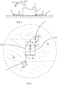
- Figure 2 shows a view from above of the industrial robot system with the sensors in the extended positions.
- the robot cell has three workstations 20, 21, 22: an input pallet 20, an output pallet 21, and a machine 22.
- the workstations are arranged within the working area of the robot.
- the sensors 4, 5 are positioned outside the working area of the robot.
- the platform 1 is provided with two arms 10, 12 connected to the platform and arranged to move the sensors 4, 5 between the retracted position and extended positions.
- the arms 4, 5 are non-extendable arms.
- the arms can be telescopic arms. In such case, the sensors are arranged so that the extended position is adjustable.
- the arms has an outer and an inner part.
- Each of the sensors 4, 5 are positioned at an outer part of one of the arms, as shown in figure 1 and 2 .
- the inner parts 16, 17 of the arms 10, 12 are connected to the platform 1.
- the arms are movably connected to the platform 1.
- arms 10, 12 are rotatably connected to the platform 1 so that they can be rotated between an extended position, as shown in figure 2 , 3 , and a retracted position, as shown in figure 1 .
- the arms are connected to the platform 1 on opposite sides of the platform and in opposite ends of the platform.
- the arms connected to a lower part of the platform 1 so that the sensors 4, 5 are close to the floor when they are in the extended position.
- the arms 10, 12 are disposed at a distance less than 0.15 m from a lower edge of the platform.
- the platform is essentially rectangular and has four corners.
- a first corner 14 and a second corner 15 are located diametrically opposite each other.
- the arm 10 is arranged to extend between the first corner 14 and the sensor 4 when the sensor 4 is in the extended positions
- the arm 12 is arranged to extend between the second corner 14 and sensor 5, when the sensor 4 is in the extended positions.
- the sensors are arranged on diametrically opposite sides of the platform when they are in the extended position so that they together cover an angle of 360° in a horizontal plane around the platform, as shown in figure 4 .
- Figure 4 illustrates the ranges of measurement 24, 26 for the sensors 4, 5 in the extended position.
- Each of the sensors 4, 5 are capable to detect motions within an angle of at least 270° in the horizontal plane.
- First sides 28, 29 and second sides 30, 31 of the platform are connected via the first and second corners 14, 15.
- the first corner 14 and a second corner 15 are located diametrically opposite each other.
- the sensors 4, 5 are disposed so that they measures along the first sides 28, 29 of the platform and in parallel with the arms 10, 12.
- the sensors measures within a range of 270° from the first sides 28, 29 towards the second sides 30, 31 of the platform.
- the sensors will cover an area around the platform outside the working area of the robot, and also the safety-relevant part of the working area of the robot. Accordingly, the safety zones A, B of the robot cell are located within the measuring range of the sensors.
- the sensors need to be calibrated before they are used. This means that the positions and directions of the sensors in relation to the mobile platform need to be determined. This can, for example, be done by using a known fixed object in the robot cell.
- the sensors 4, 5 are configured to detect a part of the mobile platform, for example, an edge of the corners 14, 15 of the platform.
- the sensor system comprises a calibration module (not shown) configured to determine the positions and directions of the sensors in relation to the mobile platform based on the detected part of the platform and to calibrate the robot based thereon.
- the sensor system is configured to detect the contour of the object/part of the platform, and to compare the position and orientation of the contour with a predetermined position and orientation of the object/part when the sensor is in a correct position and orientation. If the measured contour corresponds to the correct contour, the sensor is correctly positioned.
- the sensors can be moved outside the robot reach, and outside the robot working area so that the robot will not conceal any part of the monitored area.
- the sensors can be move to facilitate transportation, and also to adjust for different working areas.
- the sensor system controls that the sensor is in the right position by looking at a reference location or by using other sensors to check that it is in correct location.
- the monitored area is divided into several zones, warning zone, low speed zone and stop zone.
- the warning zone warns any person in the zone by visual or acoustic warnings that a moving robot is ahead. When a person cross the boundary for the low speed zone, the robot reduce the speed to a safe speed, e.g. 250 mm/s.
- the distance for the low speed zone is calculated based on persons moving speed, robot stop time and safety zone if the robot crosses a boarder.
- the distance for the low speed zone is normally 1.6 - 2.5 m outside the working area of a robot.
- the safety robot motion supervision system dynamically informs the safety control unit which work areas are affected by robot, tool and work object.
- the safety control unit tells the sensor system what zones to be set for warning zone, low speed zone and stop zone.
- the safety control unit can also be configured to adjust the size and shape of the safety zones A, B based on which robot cell the robot is located in.
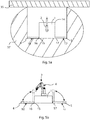
- Figure 5a shows a view from above of an industrial robot system according to a second embodiment of the invention with sensors in an extended position.
- Fig 5b shows a side view of the industrial robot system shown in figure 5a .
- Components corresponding to those in the previous figures have been given the same reference numerals, and will not be described in more detail here.
- This embodiment differs from the first embodiment in that the arms 10, 12 are disposed on a rear side of the platform, and the arms are pivotable between a horizontal and a vertical position.
- the sensors 4, 5 are located in the extended position when the arms are located in the horizontal position, and the sensors 4, 5 are located in the retracted position when the arms are located in the horizontal position.
- This embodiment is, for example suitable when the platform 1 and the robot is positioned close to a wall 35, as shown in fig 5a .
- the sensors detects about 270° in the horizontal plane.
- Figure 5a illustrates the range 37 of measurement for the sensors 4, 5 in the extended position. Due to the wall, it is not necessary to cover a range of 360° around the robot.
- the number of sensors can be more than two.
- the sensors can be configured to detect motions within an angle less than 270° in a horizontal plane. It is also possible to have more than two arms provided with sensors.
Landscapes
- Engineering & Computer Science (AREA)
- Mechanical Engineering (AREA)
- General Engineering & Computer Science (AREA)
- Robotics (AREA)
- Human Computer Interaction (AREA)
- Manufacturing & Machinery (AREA)
- Physics & Mathematics (AREA)
- General Physics & Mathematics (AREA)
- Automation & Control Theory (AREA)
- Manipulator (AREA)
Claims (13)
- Système de robot industriel comprenant :- une plateforme (1),- un robot industriel (2) positionné sur la plateforme et comportant un bras mobile de robot (6),- un système de détection comprenant deux capteurs (4, 5), chacun des capteurs étant conçu pour détecter les mouvements dans un angle d'au moins 90° dans un plan horizontal, et les capteurs étant disposés de manière à détecter les mouvements d'un objet à l'intérieur d'au moins une zone de sécurité définie par rapport aux capteurs, et- une unité de commande (7) conçue pour ajuster la vitesse du robot si un objet en mouvement est détecté dans l'au moins une zone de sécurité (A, B), la plateforme (1) étant conçue pour se trouver dans une cellule robotisée lorsque le robot effectue une tâche dans la cellule robotisée, caractérisé en ce que le système de robot comprend deux bras (10, 12) raccordés à la plateforme (1) et conçus pour déplacer les capteurs (4, 5) par rapport à la plateforme (1) entre une position rétractée et une position déployée, les capteurs étant situés à une distance d'au moins 0,5 m de la plateforme dans la position déployée, et les capteurs étant conçus pour détecter les mouvements d'un objet dans l'au moins une zone de sécurité lorsqu'ils sont dans la position déployée.
- Système de robot selon la revendication 1, dans lequel la plateforme est positionnée sur le sol de la cellule robotisée, et les capteurs (4, 5) en position déployée sont situés à une distance inférieure à 0,15 m du sol dans la direction verticale.
- Système de robot selon la revendication 1 ou 2, dans lequel le robot (2) possède une zone de travail définie, et les capteurs (4, 5) en position déployée sont situés en dehors de la zone de travail du robot.
- Système de robot selon la revendication 3, dans lequel les capteurs (4, 5) en position déployée sont situés à moins de 1 m en dehors de la zone de travail du robot, de préférence à moins de 0,5 m en dehors de la zone de travail du robot, et de plus grande préférence à moins de 0,2 m en dehors de la zone de travail du robot.
- Système de robot selon l'une quelconque des revendications précédentes, dans lequel chacun des capteurs (4, 5) est conçu pour détecter les mouvements dans un angle d'au moins 250° dans un plan horizontal, et de préférence chacun des capteurs (4, 5) est conçu pour détecter les mouvements dans un angle d'au moins 270° dans un plan horizontal.
- Système de robot selon l'une quelconque des revendications précédentes, dans lequel les capteurs (4, 5), dans la position déployée, sont disposés de manière à couvrir ensemble un angle de 360° dans un plan horizontal autour de la plateforme (1).
- Système de robot selon l'une quelconque des revendications précédentes, dans lequel les deux capteurs (4, 5) sont disposés, dans la seconde position, sur des côtés diamétralement opposés de la plateforme (1) de manière à couvrir ensemble un angle de 360° dans un plan horizontal autour de la plateforme mobile.
- Système de robot selon l'une quelconque des revendications précédentes, dans lequel la plateforme (1) est rectangulaire et ses premier et deuxième sommet (14, 15) sont diagonalement opposés, et l'un des bras (10) est conçu pour se déployer entre le premier sommet (15) et l'un des capteurs (4), lorsque le capteur est en position déployée, et l'autre bras (12) est conçu pour se déployer entre le deuxième sommet (14) et l'autre capteur (5), lorsque le capteur est en position déployée.
- Système de robot selon l'une quelconque des revendications précédentes, dans lequel les capteurs (4, 5), en position déployée, sont situés à une distance d'au moins 0,8 m de la plateforme.
- Système de robot selon l'une quelconque des revendications précédentes, dans lequel les capteurs (4, 5), en position rétractée, sont situés sur la plateforme ou à grande proximité de celle-ci.
- Système de robot selon l'une quelconque des revendications précédentes, dans lequel ladite plateforme (1) est une plateforme mobile.
- Système de robot selon l'une quelconque des revendications précédentes, dans lequel les capteurs (4, 5) sont conçus pour détecter une partie de la plateforme (1) ou un objet connu dans la cellule robotisée, et le système de détection comprend un module d'étalonnage conçu pour déterminer la position et la direction des capteurs par rapport à la plateforme à partir de la partie détectée de la plateforme ou de l'objet connu, et pour étalonner le robot à partir de ces informations.
- Système de robot selon l'une quelconque des revendications précédentes, dans lequel le système de robot comprend une pluralité de cellules robotisées et la plateforme (1) est conçue pour être déplacée entre les cellules robotisées et pour effectuer une tâche dans les cellules robotisées, et l'unité de commande (7) de sécurité est conçue pour ajuster les dimensions et la forme de l'au moins une zone de sécurité en fonction de la cellule robotisée dans laquelle est situé le robot.
Applications Claiming Priority (1)
| Application Number | Priority Date | Filing Date | Title |
|---|---|---|---|
| EP16168742.1A EP3243609A1 (fr) | 2016-05-09 | 2016-05-09 | Système de robot industriel sans barrière |
Publications (2)
| Publication Number | Publication Date |
|---|---|
| EP3248740A1 EP3248740A1 (fr) | 2017-11-29 |
| EP3248740B1 true EP3248740B1 (fr) | 2018-07-11 |
Family
ID=55968937
Family Applications (2)
| Application Number | Title | Priority Date | Filing Date |
|---|---|---|---|
| EP16168742.1A Withdrawn EP3243609A1 (fr) | 2016-05-09 | 2016-05-09 | Système de robot industriel sans barrière |
| EP17169710.5A Active EP3248740B1 (fr) | 2016-05-09 | 2017-05-05 | Système de robot industriel sans barrière |
Family Applications Before (1)
| Application Number | Title | Priority Date | Filing Date |
|---|---|---|---|
| EP16168742.1A Withdrawn EP3243609A1 (fr) | 2016-05-09 | 2016-05-09 | Système de robot industriel sans barrière |
Country Status (2)
| Country | Link |
|---|---|
| US (1) | US10500729B2 (fr) |
| EP (2) | EP3243609A1 (fr) |
Cited By (2)
| Publication number | Priority date | Publication date | Assignee | Title |
|---|---|---|---|---|
| EP3978210A4 (fr) * | 2019-05-28 | 2023-02-22 | OMRON Corporation | Système de surveillance de sécurité, dispositif de commande de surveillance de sécurité et procédé de surveillance de sécurité |
| EP4386251A1 (fr) * | 2022-12-14 | 2024-06-19 | Sick Ag | Système comprenant un capteur et procédé comprenant un capteur pour surveiller plusieurs zones de protection |
Families Citing this family (34)
| Publication number | Priority date | Publication date | Assignee | Title |
|---|---|---|---|---|
| US12103170B2 (en) | 2017-01-13 | 2024-10-01 | Clara Vu | Dynamic, interactive signaling of safety-related conditions in a monitored environment |
| US11518051B2 (en) | 2017-02-07 | 2022-12-06 | Veo Robotics, Inc. | Dynamic, interactive signaling of safety-related conditions in a monitored environment |
| CN110494900A (zh) | 2017-02-07 | 2019-11-22 | 韦奥机器人股份有限公司 | 工作空间安全监控和设备控制 |
| US11541543B2 (en) | 2017-02-07 | 2023-01-03 | Veo Robotics, Inc. | Dynamic, interactive signaling of safety-related conditions in a monitored environment |
| JP6416980B1 (ja) * | 2017-05-17 | 2018-10-31 | ファナック株式会社 | 監視領域を分割した空間領域を監視する監視装置 |
| US11014240B2 (en) * | 2017-09-05 | 2021-05-25 | Abb Schweiz Ag | Robot having dynamic safety zones |
| DE102018214439A1 (de) * | 2017-11-17 | 2019-05-23 | Volkswagen Aktiengesellschaft | Verfahren und Vorrichtung zur Absicherung eines Arbeitsbereiches eines Roboters während einer Benutzungsphase |
| JP6680752B2 (ja) | 2017-11-28 | 2020-04-15 | ファナック株式会社 | ロボットの速度を制限する制御装置 |
| US11453123B2 (en) * | 2017-12-27 | 2022-09-27 | Stmicroelectronics, Inc. | Robotic device with time-of-flight proximity sensing system |
| KR102499576B1 (ko) * | 2018-01-08 | 2023-02-15 | 삼성전자주식회사 | 전자 장치 및 그 제어 방법 |
| US12097625B2 (en) | 2018-02-06 | 2024-09-24 | Veo Robotics, Inc. | Robot end-effector sensing and identification |
| US12049014B2 (en) | 2018-02-06 | 2024-07-30 | Veo Robotics, Inc. | Workplace monitoring and semantic entity identification for safe machine operation |
| JP6748145B2 (ja) * | 2018-05-15 | 2020-08-26 | ファナック株式会社 | ロボットシステム |
| EP3569366B1 (fr) * | 2018-05-17 | 2023-06-28 | Siemens Aktiengesellschaft | Procédé et appareil de commande de robot |
| JP7155660B2 (ja) * | 2018-06-26 | 2022-10-19 | セイコーエプソン株式会社 | ロボット制御装置およびロボットシステム |
| CN108527310A (zh) * | 2018-06-27 | 2018-09-14 | 芜湖易泽中小企业公共服务股份有限公司 | 一种木材打孔机器人 |
| CN108942862A (zh) * | 2018-07-16 | 2018-12-07 | 汕头大学 | 一种复合型移动机器人 |
| FI128122B (fi) * | 2018-08-29 | 2019-10-15 | Ponsse Oyj | Ohjausjärjestely ja menetelmä metsäkoneen ohjaamiseksi |
| EP3844948B1 (fr) * | 2018-08-30 | 2023-11-01 | Veo Robotics, Inc. | Système de vision par ordinateur à détection de profondeur |
| US12452396B2 (en) | 2018-08-30 | 2025-10-21 | Symbotic Llc | Sensor for safe detection of intrusions in a 3D volume |
| US12418638B2 (en) | 2018-08-30 | 2025-09-16 | Symbotic Llc | Calibration of depth-sensing computer vision systems |
| WO2020069716A1 (fr) * | 2018-10-01 | 2020-04-09 | Abb Schweiz Ag | Opération sécurisée d'un système robotique |
| CN111940724B (zh) * | 2019-05-17 | 2024-03-29 | 天津斯沃姆科技发展有限公司 | 一种模块化增减材制造装置及方法 |
| CN110347162A (zh) * | 2019-07-29 | 2019-10-18 | 南京市晨枭软件技术有限公司 | 一种工业机器人路径自动修正的方法及系统 |
| US12296470B2 (en) * | 2019-10-21 | 2025-05-13 | Te Connectivity Solutions Gmbh | Autonomous mobile vehicle |
| CN112757347B (zh) * | 2019-11-01 | 2024-11-19 | 天津新松机器人自动化有限公司 | 一种协作机器人的安全机构 |
| JP7421346B2 (ja) * | 2020-01-17 | 2024-01-24 | 川崎重工業株式会社 | 安全装置、自走式ロボットシステム、及び制御方法 |
| WO2022136570A2 (fr) * | 2020-12-24 | 2022-06-30 | Robotise Ag | Robot de service |
| JP7623568B2 (ja) * | 2020-12-29 | 2025-01-29 | 花王株式会社 | ロボットアーム付き移動ロボット |
| WO2023066465A1 (fr) * | 2021-10-19 | 2023-04-27 | Abb Schweiz Ag | Procédés de gestion de sécurité de robot industriel, systèmes de commande et système de robot |
| SE546077C2 (en) * | 2022-05-03 | 2024-05-14 | Atlas Copco Ind Technique Ab | System and method for providing a safety stop feature of a power tool arranged to be operated by a machine |
| JP2023177840A (ja) * | 2022-06-03 | 2023-12-14 | 株式会社不二越 | ロボット制御装置及びロボット制御システム |
| EP4727728A1 (fr) * | 2023-06-16 | 2026-04-22 | Abb Schweiz Ag | Système de robot |
| DK181990B1 (en) * | 2023-10-02 | 2025-05-14 | Cobot Lift Holding Aps | An automated baggage handling robot |
Family Cites Families (51)
| Publication number | Priority date | Publication date | Assignee | Title |
|---|---|---|---|---|
| JP3419313B2 (ja) * | 1998-07-21 | 2003-06-23 | 株式会社デンソー | 生産システム |
| JP3956574B2 (ja) * | 2000-03-28 | 2007-08-08 | 松下電器産業株式会社 | 産業用ロボット |
| JP2001273032A (ja) * | 2000-03-28 | 2001-10-05 | Denso Corp | 無人移動車における障害物対処システムおよび装置 |
| JP4481549B2 (ja) * | 2002-03-04 | 2010-06-16 | 株式会社キーエンス | 多光軸光電式安全装置 |
| DE10216122A1 (de) * | 2002-04-12 | 2003-10-30 | Sick Ag | Objekterfassung |
| JP2004154916A (ja) * | 2002-11-08 | 2004-06-03 | Fanuc Ltd | 自動機械システムの安全装置 |
| DE102004041821A1 (de) | 2004-08-27 | 2006-03-16 | Abb Research Ltd. | Vorrichtung und Verfahren zur Sicherung eines maschinell gesteuerten Handhabungsgerätes |
| JP4764070B2 (ja) * | 2005-05-24 | 2011-08-31 | 本田技研工業株式会社 | 作業ステーションの安全システム |
| EP1728601A1 (fr) * | 2005-06-03 | 2006-12-06 | Abb Ab | Système robotique industriel comprenant une unité de programmation portable et des moyens pour détecter si cette unité quitte la cellule robotique |
| JP4168072B2 (ja) * | 2006-12-21 | 2008-10-22 | ファナック株式会社 | ロボットシステム |
| DE102007013299A1 (de) * | 2007-03-06 | 2008-09-11 | Cedes Ag | Sensorvorrichtung sowie Anlage mit einem Förderer und einer Sensorvorrichtung |
| DE102007028390A1 (de) * | 2007-06-15 | 2008-12-18 | Abb Research Ltd. | Prozesssteuerung, System und Verfahren zur automatisierten Anpassung von Prozessparametern wenigstens einer Handhabungsvorrichtung |
| SE532298C2 (sv) * | 2008-04-16 | 2009-12-08 | Jokab Safety Ab | Låsanordning |
| US7810697B2 (en) * | 2008-08-22 | 2010-10-12 | Honda Motor Co., Ltd. | Turntable welding system with light curtain protection |
| DE102008041602B4 (de) * | 2008-08-27 | 2015-07-30 | Deutsches Zentrum für Luft- und Raumfahrt e.V. | Roboter und Verfahren zum Steuern eines Roboters |
| SE0802217L (sv) | 2008-10-17 | 2009-12-01 | Jubo Mechatronics Ab | Industrirobotsystem med dockningsfunktion |
| WO2010063319A1 (fr) * | 2008-12-03 | 2010-06-10 | Abb Research Ltd. | Système de sécurité de robot et procédé associé |
| JP4648486B2 (ja) * | 2009-01-26 | 2011-03-09 | ファナック株式会社 | 人間とロボットとの協調動作領域を有する生産システム |
| US8415609B2 (en) * | 2009-01-31 | 2013-04-09 | Keyence Corporation | Safety photoelectric switch |
| DE102009038721A1 (de) * | 2009-08-25 | 2011-03-03 | Kuka Roboter Gmbh | Anordnung und Verfahren zur sicheren Steuerung eines Manipulators |
| US20110054690A1 (en) * | 2009-08-25 | 2011-03-03 | Ehud Gal | Electro-mechanism for extending the capabilities of bilateral robotic platforms and a method for performing the same |
| DE102009040145A1 (de) * | 2009-09-04 | 2011-03-10 | Kuka Roboter Gmbh | Verfahren und Vorrichtung zum Stillsetzen eines Manipulators |
| DE102010007027A1 (de) | 2010-02-05 | 2011-08-11 | KUKA Laboratories GmbH, 86165 | Verfahren und Vorrichtung zur Überwachung eines Manipulatorraumes |
| EP2353799B8 (fr) * | 2010-02-05 | 2018-08-08 | KUKA Deutschland GmbH | Procédé et dispositif de surveillance d'une chambre de manipulateur |
| US8855812B2 (en) | 2010-07-23 | 2014-10-07 | Chetan Kapoor | System and method for robot safety and collision avoidance |
| JP4938118B2 (ja) | 2010-08-17 | 2012-05-23 | ファナック株式会社 | 人間協調ロボットシステム |
| DE102010046327B4 (de) * | 2010-09-23 | 2021-10-28 | Kuka Roboter Gmbh | Überwachung eines mobilen Manipulators |
| DE102010063214A1 (de) * | 2010-12-16 | 2012-06-21 | Robert Bosch Gmbh | Sicherungseinrichtung für eine Handhabungsvorrichtung, insbesondere einen Industrieroboter, sowie Verfahren zum Betreiben der Sicherungseinrichtung |
| JP5160700B1 (ja) * | 2011-08-24 | 2013-03-13 | ヤマザキマザック株式会社 | Nc工作機械システム |
| US9211648B2 (en) * | 2012-04-05 | 2015-12-15 | Irobot Corporation | Operating a mobile robot |
| US20150032164A1 (en) * | 2012-06-21 | 2015-01-29 | Globus Medical, Inc. | Methods for Performing Invasive Medical Procedures Using a Surgical Robot |
| JP2014004604A (ja) * | 2012-06-25 | 2014-01-16 | Amada Co Ltd | 金型搭載用ストッカ、金型格納装置、並びに金型・ハンド格納装置及びロボットによる金型交換方法とその制御装置 |
| US9910344B2 (en) * | 2012-08-06 | 2018-03-06 | EarthCam, Inc. | In-ceiling or in-wall retracting camera platform system |
| US8849105B2 (en) * | 2012-08-06 | 2014-09-30 | EarthCam, Inc. | In-ceiling or in-wall retracting camera platform system |
| JP6123307B2 (ja) * | 2013-01-23 | 2017-05-10 | 株式会社デンソーウェーブ | ロボット周辺への物体の侵入を監視する監視システムおよび監視方法 |
| JP5590164B2 (ja) * | 2013-01-28 | 2014-09-17 | 株式会社安川電機 | ロボットシステム |
| US9207667B2 (en) * | 2013-04-16 | 2015-12-08 | Siemens Industry Software Ltd. | Automatic generation of robotic processes for symmetric products |
| DE102013104265A1 (de) | 2013-04-26 | 2014-10-30 | Pilz Gmbh & Co. Kg | Vorrichtung und Verfahren zum Absichern einer automatisiert arbeitenden Maschine |
| JP6261209B2 (ja) * | 2013-07-04 | 2018-01-17 | キヤノン株式会社 | 複数の生産装置を備えるシステム |
| JP5892132B2 (ja) * | 2013-09-13 | 2016-03-23 | 株式会社安川電機 | 制御装置及びロボットシステム |
| WO2015094092A1 (fr) * | 2013-12-18 | 2015-06-25 | Delaval Holding Ab | Effecteur, robot et système de traite rotatif |
| JP6316644B2 (ja) * | 2014-04-23 | 2018-04-25 | ファナック株式会社 | 扉の速度を制御可能なシステム |
| US9283678B2 (en) * | 2014-07-16 | 2016-03-15 | Google Inc. | Virtual safety cages for robotic devices |
| US9927797B2 (en) * | 2014-08-29 | 2018-03-27 | Amazon Technologies, Inc. | Safety compliance for mobile drive units |
| DE102014217352B4 (de) * | 2014-08-29 | 2018-04-19 | HAP Handhabungs-, Automatisierungs- und Präzisionstechnik GmbH | Verfahrbare Vorrichtung zur Manipulation von Gegenständen |
| US20160096329A1 (en) * | 2014-10-01 | 2016-04-07 | Flux Technology LLC | 3d tooling machine |
| US9365987B2 (en) * | 2014-10-29 | 2016-06-14 | SafeTBots, LLC | Portable remote-controlled traffic and pedestrian control system |
| EP3017920B1 (fr) * | 2014-11-07 | 2017-08-23 | Comau S.p.A. | Robot industriel et procédé pour commander un tel robot |
| JP6088563B2 (ja) * | 2015-02-10 | 2017-03-01 | ファナック株式会社 | 位置及び姿勢の変換演算機能を備えたワーク取出しロボットシステム、及びワーク取出し方法 |
| EP3115742B1 (fr) * | 2015-07-10 | 2020-04-15 | Hexagon Technology Center GmbH | Appareil de mesure 3d |
| CN110494900A (zh) * | 2017-02-07 | 2019-11-22 | 韦奥机器人股份有限公司 | 工作空间安全监控和设备控制 |
-
2016
- 2016-05-09 EP EP16168742.1A patent/EP3243609A1/fr not_active Withdrawn
-
2017
- 2017-05-04 US US15/586,339 patent/US10500729B2/en active Active
- 2017-05-05 EP EP17169710.5A patent/EP3248740B1/fr active Active
Non-Patent Citations (1)
| Title |
|---|
| None * |
Cited By (3)
| Publication number | Priority date | Publication date | Assignee | Title |
|---|---|---|---|---|
| EP3978210A4 (fr) * | 2019-05-28 | 2023-02-22 | OMRON Corporation | Système de surveillance de sécurité, dispositif de commande de surveillance de sécurité et procédé de surveillance de sécurité |
| EP4386251A1 (fr) * | 2022-12-14 | 2024-06-19 | Sick Ag | Système comprenant un capteur et procédé comprenant un capteur pour surveiller plusieurs zones de protection |
| US12365089B2 (en) | 2022-12-14 | 2025-07-22 | Sick Ag | System having a sensor and a method for monitoring a plurality of protected zones |
Also Published As
| Publication number | Publication date |
|---|---|
| US10500729B2 (en) | 2019-12-10 |
| EP3248740A1 (fr) | 2017-11-29 |
| EP3243609A1 (fr) | 2017-11-15 |
| US20170320212A1 (en) | 2017-11-09 |
Similar Documents
| Publication | Publication Date | Title |
|---|---|---|
| EP3248740B1 (fr) | Système de robot industriel sans barrière | |
| EP3484667B1 (fr) | Système robotique de déchargement à mécanisme d'extraction intégré | |
| US9156160B2 (en) | Robot system, calibration method, and method for producing to-be-processed material | |
| US11027431B2 (en) | Automatic calibration method for robot system | |
| EP2590787B1 (fr) | Procédé pour étalonner un robot positionné sur une plateforme mobile | |
| US5015821A (en) | Computer controlled welding robot | |
| US10302251B2 (en) | Apparatus and method for safeguarding an automatically operating machine | |
| US8315735B2 (en) | Production system having cooperating process area between human and robot | |
| US12459123B2 (en) | Robot system with object detecting sensors | |
| US11389948B2 (en) | Teaching method | |
| US10960542B2 (en) | Control device and robot system | |
| EP3484668B1 (fr) | Commandes autonomes pour un système robotique de déchargement de cartons | |
| KR20180098548A (ko) | 로봇 | |
| CN110480629A (zh) | 机器人系统 | |
| KR20220163297A (ko) | 그라인딩 장치와 이를 이용한 용접 방법 | |
| EP4070921A1 (fr) | Système de sécurité pour un robot collaboratif | |
| US20200171662A1 (en) | Monitor system for robot and robot system | |
| US20260091498A1 (en) | Robot system with object detecting sensors | |
| WO2010060475A1 (fr) | Robot industriel | |
| KR20230112356A (ko) | 안전영역 자동감지 다관절 로봇 | |
| US20220324688A1 (en) | Motion Lockout for Platform Mover System | |
| JPH11142138A (ja) | 3次元自動計測装置 | |
| CN113059579A (zh) | 一种柔性作业装置 | |
| US20240061428A1 (en) | Systems and methods of guarding a mobile robot | |
| JP6795988B2 (ja) | ロボット教示装置およびロボットの教示方法 |
Legal Events
| Date | Code | Title | Description |
|---|---|---|---|
| PUAI | Public reference made under article 153(3) epc to a published international application that has entered the european phase |
Free format text: ORIGINAL CODE: 0009012 |
|
| STAA | Information on the status of an ep patent application or granted ep patent |
Free format text: STATUS: THE APPLICATION HAS BEEN PUBLISHED |
|
| AK | Designated contracting states |
Kind code of ref document: A1 Designated state(s): AL AT BE BG CH CY CZ DE DK EE ES FI FR GB GR HR HU IE IS IT LI LT LU LV MC MK MT NL NO PL PT RO RS SE SI SK SM TR |
|
| AX | Request for extension of the european patent |
Extension state: BA ME |
|
| STAA | Information on the status of an ep patent application or granted ep patent |
Free format text: STATUS: REQUEST FOR EXAMINATION WAS MADE |
|
| 17P | Request for examination filed |
Effective date: 20171220 |
|
| RBV | Designated contracting states (corrected) |
Designated state(s): AL AT BE BG CH CY CZ DE DK EE ES FI FR GB GR HR HU IE IS IT LI LT LU LV MC MK MT NL NO PL PT RO RS SE SI SK SM TR |
|
| GRAP | Despatch of communication of intention to grant a patent |
Free format text: ORIGINAL CODE: EPIDOSNIGR1 |
|
| STAA | Information on the status of an ep patent application or granted ep patent |
Free format text: STATUS: GRANT OF PATENT IS INTENDED |
|
| INTG | Intention to grant announced |
Effective date: 20180208 |
|
| GRAS | Grant fee paid |
Free format text: ORIGINAL CODE: EPIDOSNIGR3 |
|
| GRAA | (expected) grant |
Free format text: ORIGINAL CODE: 0009210 |
|
| STAA | Information on the status of an ep patent application or granted ep patent |
Free format text: STATUS: THE PATENT HAS BEEN GRANTED |
|
| AK | Designated contracting states |
Kind code of ref document: B1 Designated state(s): AL AT BE BG CH CY CZ DE DK EE ES FI FR GB GR HR HU IE IS IT LI LT LU LV MC MK MT NL NO PL PT RO RS SE SI SK SM TR |
|
| REG | Reference to a national code |
Ref country code: GB Ref legal event code: FG4D |
|
| REG | Reference to a national code |
Ref country code: CH Ref legal event code: EP |
|
| REG | Reference to a national code |
Ref country code: AT Ref legal event code: REF Ref document number: 1016403 Country of ref document: AT Kind code of ref document: T Effective date: 20180715 |
|
| REG | Reference to a national code |
Ref country code: IE Ref legal event code: FG4D |
|
| REG | Reference to a national code |
Ref country code: DE Ref legal event code: R096 Ref document number: 602017000141 Country of ref document: DE |
|
| REG | Reference to a national code |
Ref country code: SE Ref legal event code: TRGR |
|
| REG | Reference to a national code |
Ref country code: NL Ref legal event code: MP Effective date: 20180711 |
|
| REG | Reference to a national code |
Ref country code: LT Ref legal event code: MG4D |
|
| REG | Reference to a national code |
Ref country code: AT Ref legal event code: MK05 Ref document number: 1016403 Country of ref document: AT Kind code of ref document: T Effective date: 20180711 |
|
| PG25 | Lapsed in a contracting state [announced via postgrant information from national office to epo] |
Ref country code: NL Free format text: LAPSE BECAUSE OF FAILURE TO SUBMIT A TRANSLATION OF THE DESCRIPTION OR TO PAY THE FEE WITHIN THE PRESCRIBED TIME-LIMIT Effective date: 20180711 |
|
| PG25 | Lapsed in a contracting state [announced via postgrant information from national office to epo] |
Ref country code: NO Free format text: LAPSE BECAUSE OF FAILURE TO SUBMIT A TRANSLATION OF THE DESCRIPTION OR TO PAY THE FEE WITHIN THE PRESCRIBED TIME-LIMIT Effective date: 20181011 Ref country code: FI Free format text: LAPSE BECAUSE OF FAILURE TO SUBMIT A TRANSLATION OF THE DESCRIPTION OR TO PAY THE FEE WITHIN THE PRESCRIBED TIME-LIMIT Effective date: 20180711 Ref country code: BG Free format text: LAPSE BECAUSE OF FAILURE TO SUBMIT A TRANSLATION OF THE DESCRIPTION OR TO PAY THE FEE WITHIN THE PRESCRIBED TIME-LIMIT Effective date: 20181011 Ref country code: AT Free format text: LAPSE BECAUSE OF FAILURE TO SUBMIT A TRANSLATION OF THE DESCRIPTION OR TO PAY THE FEE WITHIN THE PRESCRIBED TIME-LIMIT Effective date: 20180711 Ref country code: RS Free format text: LAPSE BECAUSE OF FAILURE TO SUBMIT A TRANSLATION OF THE DESCRIPTION OR TO PAY THE FEE WITHIN THE PRESCRIBED TIME-LIMIT Effective date: 20180711 Ref country code: GR Free format text: LAPSE BECAUSE OF FAILURE TO SUBMIT A TRANSLATION OF THE DESCRIPTION OR TO PAY THE FEE WITHIN THE PRESCRIBED TIME-LIMIT Effective date: 20181012 Ref country code: PL Free format text: LAPSE BECAUSE OF FAILURE TO SUBMIT A TRANSLATION OF THE DESCRIPTION OR TO PAY THE FEE WITHIN THE PRESCRIBED TIME-LIMIT Effective date: 20180711 Ref country code: LT Free format text: LAPSE BECAUSE OF FAILURE TO SUBMIT A TRANSLATION OF THE DESCRIPTION OR TO PAY THE FEE WITHIN THE PRESCRIBED TIME-LIMIT Effective date: 20180711 Ref country code: IS Free format text: LAPSE BECAUSE OF FAILURE TO SUBMIT A TRANSLATION OF THE DESCRIPTION OR TO PAY THE FEE WITHIN THE PRESCRIBED TIME-LIMIT Effective date: 20181111 |
|
| PG25 | Lapsed in a contracting state [announced via postgrant information from national office to epo] |
Ref country code: HR Free format text: LAPSE BECAUSE OF FAILURE TO SUBMIT A TRANSLATION OF THE DESCRIPTION OR TO PAY THE FEE WITHIN THE PRESCRIBED TIME-LIMIT Effective date: 20180711 Ref country code: LV Free format text: LAPSE BECAUSE OF FAILURE TO SUBMIT A TRANSLATION OF THE DESCRIPTION OR TO PAY THE FEE WITHIN THE PRESCRIBED TIME-LIMIT Effective date: 20180711 Ref country code: AL Free format text: LAPSE BECAUSE OF FAILURE TO SUBMIT A TRANSLATION OF THE DESCRIPTION OR TO PAY THE FEE WITHIN THE PRESCRIBED TIME-LIMIT Effective date: 20180711 |
|
| REG | Reference to a national code |
Ref country code: DE Ref legal event code: R097 Ref document number: 602017000141 Country of ref document: DE |
|
| PG25 | Lapsed in a contracting state [announced via postgrant information from national office to epo] |
Ref country code: EE Free format text: LAPSE BECAUSE OF FAILURE TO SUBMIT A TRANSLATION OF THE DESCRIPTION OR TO PAY THE FEE WITHIN THE PRESCRIBED TIME-LIMIT Effective date: 20180711 Ref country code: CZ Free format text: LAPSE BECAUSE OF FAILURE TO SUBMIT A TRANSLATION OF THE DESCRIPTION OR TO PAY THE FEE WITHIN THE PRESCRIBED TIME-LIMIT Effective date: 20180711 Ref country code: RO Free format text: LAPSE BECAUSE OF FAILURE TO SUBMIT A TRANSLATION OF THE DESCRIPTION OR TO PAY THE FEE WITHIN THE PRESCRIBED TIME-LIMIT Effective date: 20180711 Ref country code: ES Free format text: LAPSE BECAUSE OF FAILURE TO SUBMIT A TRANSLATION OF THE DESCRIPTION OR TO PAY THE FEE WITHIN THE PRESCRIBED TIME-LIMIT Effective date: 20180711 |
|
| PLBE | No opposition filed within time limit |
Free format text: ORIGINAL CODE: 0009261 |
|
| STAA | Information on the status of an ep patent application or granted ep patent |
Free format text: STATUS: NO OPPOSITION FILED WITHIN TIME LIMIT |
|
| PG25 | Lapsed in a contracting state [announced via postgrant information from national office to epo] |
Ref country code: SK Free format text: LAPSE BECAUSE OF FAILURE TO SUBMIT A TRANSLATION OF THE DESCRIPTION OR TO PAY THE FEE WITHIN THE PRESCRIBED TIME-LIMIT Effective date: 20180711 Ref country code: DK Free format text: LAPSE BECAUSE OF FAILURE TO SUBMIT A TRANSLATION OF THE DESCRIPTION OR TO PAY THE FEE WITHIN THE PRESCRIBED TIME-LIMIT Effective date: 20180711 Ref country code: SM Free format text: LAPSE BECAUSE OF FAILURE TO SUBMIT A TRANSLATION OF THE DESCRIPTION OR TO PAY THE FEE WITHIN THE PRESCRIBED TIME-LIMIT Effective date: 20180711 |
|
| 26N | No opposition filed |
Effective date: 20190412 |
|
| PG25 | Lapsed in a contracting state [announced via postgrant information from national office to epo] |
Ref country code: SI Free format text: LAPSE BECAUSE OF FAILURE TO SUBMIT A TRANSLATION OF THE DESCRIPTION OR TO PAY THE FEE WITHIN THE PRESCRIBED TIME-LIMIT Effective date: 20180711 |
|
| PG25 | Lapsed in a contracting state [announced via postgrant information from national office to epo] |
Ref country code: MC Free format text: LAPSE BECAUSE OF FAILURE TO SUBMIT A TRANSLATION OF THE DESCRIPTION OR TO PAY THE FEE WITHIN THE PRESCRIBED TIME-LIMIT Effective date: 20180711 |
|
| PG25 | Lapsed in a contracting state [announced via postgrant information from national office to epo] |
Ref country code: LU Free format text: LAPSE BECAUSE OF NON-PAYMENT OF DUE FEES Effective date: 20190505 |
|
| PG25 | Lapsed in a contracting state [announced via postgrant information from national office to epo] |
Ref country code: TR Free format text: LAPSE BECAUSE OF FAILURE TO SUBMIT A TRANSLATION OF THE DESCRIPTION OR TO PAY THE FEE WITHIN THE PRESCRIBED TIME-LIMIT Effective date: 20180711 |
|
| PG25 | Lapsed in a contracting state [announced via postgrant information from national office to epo] |
Ref country code: IE Free format text: LAPSE BECAUSE OF NON-PAYMENT OF DUE FEES Effective date: 20190505 |
|
| PG25 | Lapsed in a contracting state [announced via postgrant information from national office to epo] |
Ref country code: PT Free format text: LAPSE BECAUSE OF FAILURE TO SUBMIT A TRANSLATION OF THE DESCRIPTION OR TO PAY THE FEE WITHIN THE PRESCRIBED TIME-LIMIT Effective date: 20181111 |
|
| PG25 | Lapsed in a contracting state [announced via postgrant information from national office to epo] |
Ref country code: CY Free format text: LAPSE BECAUSE OF FAILURE TO SUBMIT A TRANSLATION OF THE DESCRIPTION OR TO PAY THE FEE WITHIN THE PRESCRIBED TIME-LIMIT Effective date: 20180711 |
|
| PG25 | Lapsed in a contracting state [announced via postgrant information from national office to epo] |
Ref country code: MT Free format text: LAPSE BECAUSE OF FAILURE TO SUBMIT A TRANSLATION OF THE DESCRIPTION OR TO PAY THE FEE WITHIN THE PRESCRIBED TIME-LIMIT Effective date: 20180711 Ref country code: HU Free format text: LAPSE BECAUSE OF FAILURE TO SUBMIT A TRANSLATION OF THE DESCRIPTION OR TO PAY THE FEE WITHIN THE PRESCRIBED TIME-LIMIT; INVALID AB INITIO Effective date: 20170505 |
|
| PG25 | Lapsed in a contracting state [announced via postgrant information from national office to epo] |
Ref country code: MK Free format text: LAPSE BECAUSE OF FAILURE TO SUBMIT A TRANSLATION OF THE DESCRIPTION OR TO PAY THE FEE WITHIN THE PRESCRIBED TIME-LIMIT Effective date: 20180711 |
|
| P01 | Opt-out of the competence of the unified patent court (upc) registered |
Effective date: 20230602 |
|
| PGFP | Annual fee paid to national office [announced via postgrant information from national office to epo] |
Ref country code: DE Payment date: 20250520 Year of fee payment: 9 |
|
| PGFP | Annual fee paid to national office [announced via postgrant information from national office to epo] |
Ref country code: GB Payment date: 20250519 Year of fee payment: 9 |
|
| PGFP | Annual fee paid to national office [announced via postgrant information from national office to epo] |
Ref country code: BE Payment date: 20250522 Year of fee payment: 9 Ref country code: IT Payment date: 20250520 Year of fee payment: 9 |
|
| PGFP | Annual fee paid to national office [announced via postgrant information from national office to epo] |
Ref country code: FR Payment date: 20250516 Year of fee payment: 9 |
|
| PGFP | Annual fee paid to national office [announced via postgrant information from national office to epo] |
Ref country code: CH Payment date: 20250601 Year of fee payment: 9 |
|
| PGFP | Annual fee paid to national office [announced via postgrant information from national office to epo] |
Ref country code: SE Payment date: 20250520 Year of fee payment: 9 |