EP3248760A1 - Vorrichtung zur dreidimensionalen generativen fertigung, verfahren zur steuerung der vorrichtung zur dreidimensionalen generativen fertigung und programm zur steuerung der vorrichtung zur dreidimensionalen generativen fertigung - Google Patents
Vorrichtung zur dreidimensionalen generativen fertigung, verfahren zur steuerung der vorrichtung zur dreidimensionalen generativen fertigung und programm zur steuerung der vorrichtung zur dreidimensionalen generativen fertigung Download PDFInfo
- Publication number
- EP3248760A1 EP3248760A1 EP16825689.9A EP16825689A EP3248760A1 EP 3248760 A1 EP3248760 A1 EP 3248760A1 EP 16825689 A EP16825689 A EP 16825689A EP 3248760 A1 EP3248760 A1 EP 3248760A1
- Authority
- EP
- European Patent Office
- Prior art keywords
- shaping
- dimensional
- shaped object
- dimensional laminated
- base material
- Prior art date
- Legal status (The legal status is an assumption and is not a legal conclusion. Google has not performed a legal analysis and makes no representation as to the accuracy of the status listed.)
- Withdrawn
Links
Images




Classifications
-
- B—PERFORMING OPERATIONS; TRANSPORTING
- B29—WORKING OF PLASTICS; WORKING OF SUBSTANCES IN A PLASTIC STATE IN GENERAL
- B29C—SHAPING OR JOINING OF PLASTICS; SHAPING OF MATERIAL IN A PLASTIC STATE, NOT OTHERWISE PROVIDED FOR; AFTER-TREATMENT OF THE SHAPED PRODUCTS, e.g. REPAIRING
- B29C64/00—Additive manufacturing, i.e. manufacturing of three-dimensional [3D] objects by additive deposition, additive agglomeration or additive layering, e.g. by 3D printing, stereolithography or selective laser sintering
- B29C64/10—Processes of additive manufacturing
- B29C64/141—Processes of additive manufacturing using only solid materials
- B29C64/153—Processes of additive manufacturing using only solid materials using layers of powder being selectively joined, e.g. by selective laser sintering or melting
-
- B—PERFORMING OPERATIONS; TRANSPORTING
- B22—CASTING; POWDER METALLURGY
- B22F—WORKING METALLIC POWDER; MANUFACTURE OF ARTICLES FROM METALLIC POWDER; MAKING METALLIC POWDER; APPARATUS OR DEVICES SPECIALLY ADAPTED FOR METALLIC POWDER
- B22F12/00—Apparatus or devices specially adapted for additive manufacturing; Auxiliary means for additive manufacturing; Combinations of additive manufacturing apparatus or devices with other processing apparatus or devices
- B22F12/60—Planarisation devices; Compression devices
- B22F12/67—Blades
-
- B—PERFORMING OPERATIONS; TRANSPORTING
- B23—MACHINE TOOLS; METAL-WORKING NOT OTHERWISE PROVIDED FOR
- B23K—SOLDERING OR UNSOLDERING; WELDING; CLADDING OR PLATING BY SOLDERING OR WELDING; CUTTING BY APPLYING HEAT LOCALLY, e.g. FLAME CUTTING; WORKING BY LASER BEAM
- B23K15/00—Electron-beam welding or cutting
- B23K15/0046—Welding
- B23K15/0086—Welding welding for purposes other than joining, e.g. build-up welding
-
- B—PERFORMING OPERATIONS; TRANSPORTING
- B23—MACHINE TOOLS; METAL-WORKING NOT OTHERWISE PROVIDED FOR
- B23K—SOLDERING OR UNSOLDERING; WELDING; CLADDING OR PLATING BY SOLDERING OR WELDING; CUTTING BY APPLYING HEAT LOCALLY, e.g. FLAME CUTTING; WORKING BY LASER BEAM
- B23K15/00—Electron-beam welding or cutting
- B23K15/0046—Welding
- B23K15/0093—Welding characterised by the properties of the materials to be welded
-
- B—PERFORMING OPERATIONS; TRANSPORTING
- B23—MACHINE TOOLS; METAL-WORKING NOT OTHERWISE PROVIDED FOR
- B23K—SOLDERING OR UNSOLDERING; WELDING; CLADDING OR PLATING BY SOLDERING OR WELDING; CUTTING BY APPLYING HEAT LOCALLY, e.g. FLAME CUTTING; WORKING BY LASER BEAM
- B23K15/00—Electron-beam welding or cutting
- B23K15/06—Electron-beam welding or cutting within a vacuum chamber
-
- B—PERFORMING OPERATIONS; TRANSPORTING
- B29—WORKING OF PLASTICS; WORKING OF SUBSTANCES IN A PLASTIC STATE IN GENERAL
- B29C—SHAPING OR JOINING OF PLASTICS; SHAPING OF MATERIAL IN A PLASTIC STATE, NOT OTHERWISE PROVIDED FOR; AFTER-TREATMENT OF THE SHAPED PRODUCTS, e.g. REPAIRING
- B29C64/00—Additive manufacturing, i.e. manufacturing of three-dimensional [3D] objects by additive deposition, additive agglomeration or additive layering, e.g. by 3D printing, stereolithography or selective laser sintering
- B29C64/20—Apparatus for additive manufacturing; Details thereof or accessories therefor
- B29C64/205—Means for applying layers
-
- B—PERFORMING OPERATIONS; TRANSPORTING
- B29—WORKING OF PLASTICS; WORKING OF SUBSTANCES IN A PLASTIC STATE IN GENERAL
- B29C—SHAPING OR JOINING OF PLASTICS; SHAPING OF MATERIAL IN A PLASTIC STATE, NOT OTHERWISE PROVIDED FOR; AFTER-TREATMENT OF THE SHAPED PRODUCTS, e.g. REPAIRING
- B29C64/00—Additive manufacturing, i.e. manufacturing of three-dimensional [3D] objects by additive deposition, additive agglomeration or additive layering, e.g. by 3D printing, stereolithography or selective laser sintering
- B29C64/20—Apparatus for additive manufacturing; Details thereof or accessories therefor
- B29C64/264—Arrangements for irradiation
- B29C64/268—Arrangements for irradiation using laser beams; using electron beams [EB]
-
- B—PERFORMING OPERATIONS; TRANSPORTING
- B33—ADDITIVE MANUFACTURING TECHNOLOGY
- B33Y—ADDITIVE MANUFACTURING, i.e. MANUFACTURING OF THREE-DIMENSIONAL [3D] OBJECTS BY ADDITIVE DEPOSITION, ADDITIVE AGGLOMERATION OR ADDITIVE LAYERING, e.g. BY 3D PRINTING, STEREOLITHOGRAPHY OR SELECTIVE LASER SINTERING
- B33Y30/00—Apparatus for additive manufacturing; Details thereof or accessories therefor
-
- B—PERFORMING OPERATIONS; TRANSPORTING
- B22—CASTING; POWDER METALLURGY
- B22F—WORKING METALLIC POWDER; MANUFACTURE OF ARTICLES FROM METALLIC POWDER; MAKING METALLIC POWDER; APPARATUS OR DEVICES SPECIALLY ADAPTED FOR METALLIC POWDER
- B22F10/00—Additive manufacturing of workpieces or articles from metallic powder
- B22F10/20—Direct sintering or melting
- B22F10/28—Powder bed fusion, e.g. selective laser melting [SLM] or electron beam melting [EBM]
-
- B—PERFORMING OPERATIONS; TRANSPORTING
- B29—WORKING OF PLASTICS; WORKING OF SUBSTANCES IN A PLASTIC STATE IN GENERAL
- B29C—SHAPING OR JOINING OF PLASTICS; SHAPING OF MATERIAL IN A PLASTIC STATE, NOT OTHERWISE PROVIDED FOR; AFTER-TREATMENT OF THE SHAPED PRODUCTS, e.g. REPAIRING
- B29C64/00—Additive manufacturing, i.e. manufacturing of three-dimensional [3D] objects by additive deposition, additive agglomeration or additive layering, e.g. by 3D printing, stereolithography or selective laser sintering
- B29C64/20—Apparatus for additive manufacturing; Details thereof or accessories therefor
- B29C64/245—Platforms or substrates
-
- B—PERFORMING OPERATIONS; TRANSPORTING
- B29—WORKING OF PLASTICS; WORKING OF SUBSTANCES IN A PLASTIC STATE IN GENERAL
- B29C—SHAPING OR JOINING OF PLASTICS; SHAPING OF MATERIAL IN A PLASTIC STATE, NOT OTHERWISE PROVIDED FOR; AFTER-TREATMENT OF THE SHAPED PRODUCTS, e.g. REPAIRING
- B29C64/00—Additive manufacturing, i.e. manufacturing of three-dimensional [3D] objects by additive deposition, additive agglomeration or additive layering, e.g. by 3D printing, stereolithography or selective laser sintering
- B29C64/30—Auxiliary operations or equipment
- B29C64/386—Data acquisition or data processing for additive manufacturing
- B29C64/393—Data acquisition or data processing for additive manufacturing for controlling or regulating additive manufacturing processes
-
- B—PERFORMING OPERATIONS; TRANSPORTING
- B33—ADDITIVE MANUFACTURING TECHNOLOGY
- B33Y—ADDITIVE MANUFACTURING, i.e. MANUFACTURING OF THREE-DIMENSIONAL [3D] OBJECTS BY ADDITIVE DEPOSITION, ADDITIVE AGGLOMERATION OR ADDITIVE LAYERING, e.g. BY 3D PRINTING, STEREOLITHOGRAPHY OR SELECTIVE LASER SINTERING
- B33Y10/00—Processes of additive manufacturing
-
- B—PERFORMING OPERATIONS; TRANSPORTING
- B33—ADDITIVE MANUFACTURING TECHNOLOGY
- B33Y—ADDITIVE MANUFACTURING, i.e. MANUFACTURING OF THREE-DIMENSIONAL [3D] OBJECTS BY ADDITIVE DEPOSITION, ADDITIVE AGGLOMERATION OR ADDITIVE LAYERING, e.g. BY 3D PRINTING, STEREOLITHOGRAPHY OR SELECTIVE LASER SINTERING
- B33Y50/00—Data acquisition or data processing for additive manufacturing
- B33Y50/02—Data acquisition or data processing for additive manufacturing for controlling or regulating additive manufacturing processes
-
- Y—GENERAL TAGGING OF NEW TECHNOLOGICAL DEVELOPMENTS; GENERAL TAGGING OF CROSS-SECTIONAL TECHNOLOGIES SPANNING OVER SEVERAL SECTIONS OF THE IPC; TECHNICAL SUBJECTS COVERED BY FORMER USPC CROSS-REFERENCE ART COLLECTIONS [XRACs] AND DIGESTS
- Y02—TECHNOLOGIES OR APPLICATIONS FOR MITIGATION OR ADAPTATION AGAINST CLIMATE CHANGE
- Y02P—CLIMATE CHANGE MITIGATION TECHNOLOGIES IN THE PRODUCTION OR PROCESSING OF GOODS
- Y02P10/00—Technologies related to metal processing
- Y02P10/25—Process efficiency
Definitions
- the present invention relates to a three-dimensional laminating and shaping apparatus, a three-dimensional laminating and shaping apparatus control method, and a three-dimensional laminating and shaping apparatus control program.
- patent literature 1 has disclosed a technique which sets the Young's modulus of a shaping plate at 150 to 800 GPa.
- Patent literature 1 Japanese Patent No. 5302710
- the present invention enables to provide a technique of solving the above-described problem.
- One aspect of the present invention provides a three-dimensional laminating and shaping apparatus comprising:
- Another aspect of the present invention provides a three-dimensional laminating and shaping apparatus control method comprising:
- Still another aspect of the present invention provides a three-dimensional laminating and shaping apparatus control program for causing a computer to execute a method, comprising:
- the present invention can effectively suppress a decrease in shaping accuracy based on a difference between the thermal expansion coefficients of a three-dimensional laminated and shaped object and shaping plate.
- a three-dimensional laminating and shaping apparatus 100 as the first embodiment of the present invention will be explained with reference to Figs. 1 to 4 .
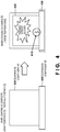
- Fig. 4 is a view for explaining a three-dimensional laminated and shaped object to be shaped by a three-dimensional laminating and shaping apparatus according to the technical premise of the three-dimensional laminating and shaping apparatus according to this embodiment.
- a three-dimensional laminated and shaped object 430 is at a high temperature and expanded due to heat given by an electron beam.
- the three-dimensional laminated and shaped object 430 is cooled after the completion of shaping, the three-dimensional laminated and shaped object 430 shrinks as cooling advances. During this shrinkage, however, thermal stress occurs, and a defect 410 forms in the three-dimensional laminated and shaped object 430, or the shape of the three-dimensional laminated and shaped object 430 warps, so the shaping accuracy decreases.
- a thermal expansion coefficient A of the three-dimensional laminated and shaped object 430 is larger than a thermal expansion coefficient B of a shaping plate (base plate) 406
- thermal stress occurs in the three-dimensional laminated and shaped object 430, and the defect 410 or the like forms in the three-dimensional laminated and shaped object 430, so the shaping accuracy decreases. That is, since the thermal expansion coefficient of the shaping plate 406 is smaller than that of the three-dimensional laminated and shaped object 430, a force which pulls the three-dimensional laminated and shaped object 430 acts on it, and the defect 410 forms in the three-dimensional laminated and shaped object 430.
- Fig. 1 is a view showing the arrangement of the three-dimensional laminating and shaping apparatus according to this embodiment.
- the three-dimensional laminating and shaping apparatus 100 includes a vacuum vessel 101, an electron gun 102, a shaping frame table 103, a Z-axis driving mechanism 104, a linear funnel 105, and a shaping plate 106. Note that in the following explanation, the three-dimensional laminating and shaping apparatus 100 is a powder bed type apparatus.
- the three-dimensional laminating and shaping apparatus 100 sets the upper surface of the shaping plate 106 at almost the same height as that of the upper surface of the shaping frame table 103. Then, the three-dimensional laminating and shaping apparatus 100 spreads the material of a three-dimensional laminated and shaped object 130 on the shaping plate 106 (on a base plate) by the liner funnel 105 as a material recoater filled with the material. The three-dimensional laminating and shaping apparatus 100 irradiates the spread material with an electron beam 121 generated by the electron gun 102, thereby melting the material, solidifying the material, and completing laminating of the material of one layer. Note that the material of the shaping plate 106 is typically stainless steel, but is not limited to this.
- the three-dimensional laminating and shaping apparatus 100 moves down a shaping table 140 by a height corresponding to the height of one layer by the Z-axis driving mechanism 104, and spreads the material of the next layer by the linear funnel 105. After spreading the material, the three-dimensional laminating and shaping apparatus 100 irradiates the material with the electron beam 121, thereby melting the material, solidifying the material, and completing laminating of the material of the next one layer.
- the three-dimensional laminating and shaping apparatus 100 shapes a desired three-dimensional laminated and shaped object in the vacuum vessel 101 by repeating this operation.
- Fig. 2 is a view for explaining the three-dimensional laminated and shaped object to be shaped by the three-dimensional laminating and shaping apparatus according to this embodiment.
- the three-dimensional laminated and shaped object 130 is shaped on the shaping plate 106 as a shaping base material.
- the three-dimensional laminated and shaped object 130 is at a high temperature and thermally expanded due to heat (energy) given by the electron beam 121.
- the shaping plate 106 and three-dimensional laminated and shaped object 130 have equal thermal expansion coefficients or close thermal expansion coefficients (a difference between them is equal to or smaller than a predetermined value). Therefore, there is no difference between the shrinkage factors during cooling, so the shaping plate 106 and three-dimensional laminated and shaped object 103 cool and solidify without pulling each other.
- the shaping plate 106 and three-dimensional laminated and shaped object 130 have only small differences between the degrees of expansion and shrinkage. This suppresses damage to the three-dimensional laminated and shaped object 130 after the three-dimensional laminated and shaped object 130 has completely cooled and solidified (at room temperature).
- the shaping base material has been explained by taking the shaping plate 106 as an example, but the shaping base material is not limited to this and may also be, e.g., another three-dimensional laminated and shaped object. That is, the technique of this embodiment is applicable even when shaping a three-dimensional laminated and shaped object on a given product or part.
- Fig. 3 is a flowchart for explaining the procedure of the three-dimensional laminating and shaping apparatus 100 according to this embodiment.
- the three-dimensional laminating and shaping apparatus 100 acquires shaping data of the three-dimensional laminated and shaped object 130.
- the three-dimensional laminating and shaping apparatus 100 selects the shaping plate 106 having a thermal expansion coefficient which is equal to that of the three-dimensional laminated and shaped object 130 or by which the difference between them is equal to or smaller than a predetermined value.
- the three-dimensional laminating and shaping apparatus 100 recoats the material of the three-dimensional laminated and shaped object 130 on the shaping plate 106, and irradiates the recoated material with the electron beam 121.
- step S307 the three-dimensional laminating and shaping apparatus 100 determines whether shaping of the three-dimensional laminated and shaped object 130 is complete. If the three-dimensional laminating and shaping apparatus 100 determines that shaping is not complete (NO in step S307), the three-dimensional laminating and shaping apparatus 100 repeats the steps from step S305. If the three-dimensional laminating and shaping apparatus 100 determines that shaping is complete (YES in step S307), the three-dimensional laminating and shaping apparatus 100 terminates the process.
- This embodiment can effectively suppress a decrease in shaping accuracy based on the difference between the thermal expansion coefficients of a three-dimensional laminated and shaped object and shaping plate, thereby reducing damage to the three-dimensional laminated and shaped object. It is also possible to effectively suppress a defect and thermal strain caused by the difference between the thermal expansion coefficients.
- a three-dimensional laminated and shaped object to be shaped by a three-dimensional laminating and shaping apparatus will be explained with reference to Fig. 5 .
- grooves are engraved on the surface of a shaping plate 506 as a shaping base material, i.e., projections and recesses are formed on the surface of the shaping plate 506.
- the projections and recesses on the surface of the shaping plate 506 are formed on a surface on which a three-dimensional laminated and shaped object 130 is laminated and shaped, i.e., on the upper surface of the shaping plate 506.
- shape of the projections and recesses formed on the surface of the shaping base material is not limited to the groove shape, and may also be a wave-like shape or zigzag shape.
- the projections and recesses are formed on the shaping plate surface, so it is possible to reduce stress acting on a three-dimensional laminated and shaped object as the shaping plate expands and shrinks. This makes it possible to suppress a defect and thermal strain. It is also possible to reduce damage to the three-dimensional laminated and shaped object. In addition, it is possible to suppress a decrease in shaping accuracy based on the difference between the thermal expansion coefficients of the three-dimensional laminated and shaped object and shaping plate. Furthermore, a defect and thermal strain caused by the difference between the thermal expansion coefficients can be suppressed.
- a three-dimensional laminated and shaped object to be shaped by a three-dimensional laminating and shaping apparatus according to the third embodiment of the present invention will be explained below with reference to Fig. 6 .
- a shaping plate 106 as a shaping base material and a three-dimensional laminated and shaped object 130 are made of different materials.
- an interlayer is formed between the shaping plate 106 as a shaping base material and the three-dimensional laminated and shaped object 130. That is, this embodiment has an arrangement in which another shaping plate 601 is formed as an interlayer on the upper surface of the shaping plate 106.
- the shaping plate 601 as an interlayer is formed in order to prevent a defect or the like in the three-dimensional laminated and shaped object 130 due to the difference in expansion and shrinkage between the shaping plate 106 and three-dimensional laminated and shaped object 130. Even if a defect occurs, this defect forms in the shaping plate 601 as an interlayer, thereby preventing the defect caused by the influence of thermal stress from occurring in the three-dimensional laminated and shaped object 130.
- the shape of the shaping plate 601 as an interlayer can be a flat plate shape, but may also be a lattice shape. For example, if thermal stress occurs when the shaping plate 601 has a lattice shape, it is possible to let only a portion where the thermal stress has occurred be broken. Consequently, the influence of thermal stress on the three-dimensional laminated and shaped object 130 can be reduced.
- This embodiment can reduce the influence of thermal stress on the three-dimensional laminated and shaped object because the interlayer is formed. It is also possible to suppress a decrease in shaping accuracy based on the difference in thermal expansion coefficient between the three-dimensional laminated and shaped object and shaping plate. Furthermore, a defect and thermal strain caused by the difference between the thermal expansion coefficients can be suppressed.
- a three-dimensional laminated and shaped object to be shaped by a three-dimensional laminating and shaping apparatus according to the fourth embodiment of the present invention will be explained below with reference to Fig. 7 .
- a plurality of interlayers are formed between a shaping base material 106 and a three-dimensional laminated and shaped object 130. That is, when the thermal expansion coefficients of the shaping plate 106 and three-dimensional laminated and shaped object 130 are largely different, the plurality of interlayers are formed to gradually reduce the influence of thermal stress conducted from the shaping plate 106 to the three-dimensional laminated and shaped object 130.
- A be the thermal expansion coefficient of the three-dimensional laminated and shaped object 130
- B be the thermal expansion coefficient of the shaping plate 106.
- the thermal expansion coefficient of a shaping plate 701 as an interlayer right above the shaping plate 106 is set at B ⁇ ⁇ which is close to the shaping plate 106
- the thermal expansion coefficient of a shaping plate 702 on the shaping plate 701 is set at A ⁇ ⁇ which is close to the three-dimensional laminated and shaped object 130.
- a thermal expansion coefficient ⁇ is so small that no thermal stress occurs.
- the influence of thermal stress on the three-dimensional laminated and shaped object can gradually be reduced because the plurality of interlayers are formed. This finally makes it possible to suppress the occurrence of damage to the three-dimensional laminated and shaped object. It is also possible to suppress a decrease in shaping accuracy based on the difference in thermal expansion coefficient between the three-dimensional laminated and shaped object and shaping plate. Furthermore, a defect and thermal strain caused by the difference between the thermal expansion coefficients can be suppressed.
- the present invention is applicable to a system including a plurality of devices or a single apparatus.
- the present invention is also applicable even when an information processing program for implementing the functions of the embodiments is supplied to the system or apparatus directly or from a remote site.
- the present invention also incorporates the program installed in a computer to implement the functions of the present invention by the computer, a medium storing the program, and a WWW (World Wide Web) server that causes a user to download the program.
- the present invention incorporates at least a non-transitory computer readable medium storing a program that causes a computer to execute processing steps included in the above-described embodiments.
Landscapes
- Engineering & Computer Science (AREA)
- Chemical & Material Sciences (AREA)
- Materials Engineering (AREA)
- Mechanical Engineering (AREA)
- Physics & Mathematics (AREA)
- Optics & Photonics (AREA)
- Manufacturing & Machinery (AREA)
- Plasma & Fusion (AREA)
- Health & Medical Sciences (AREA)
- Toxicology (AREA)
- Powder Metallurgy (AREA)
Applications Claiming Priority (1)
| Application Number | Priority Date | Filing Date | Title |
|---|---|---|---|
| PCT/JP2016/059645 WO2017163405A1 (ja) | 2016-03-25 | 2016-03-25 | 3次元積層造形装置、3次元積層造形装置の制御方法および3次元積層造形装置の制御プログラム |
Publications (2)
| Publication Number | Publication Date |
|---|---|
| EP3248760A1 true EP3248760A1 (de) | 2017-11-29 |
| EP3248760A4 EP3248760A4 (de) | 2018-05-16 |
Family
ID=59900991
Family Applications (1)
| Application Number | Title | Priority Date | Filing Date |
|---|---|---|---|
| EP16825689.9A Withdrawn EP3248760A4 (de) | 2016-03-25 | 2016-03-25 | Vorrichtung zur dreidimensionalen generativen fertigung, verfahren zur steuerung der vorrichtung zur dreidimensionalen generativen fertigung und programm zur steuerung der vorrichtung zur dreidimensionalen generativen fertigung |
Country Status (4)
| Country | Link |
|---|---|
| US (1) | US20180147779A1 (de) |
| EP (1) | EP3248760A4 (de) |
| JP (1) | JP6220459B1 (de) |
| WO (1) | WO2017163405A1 (de) |
Cited By (1)
| Publication number | Priority date | Publication date | Assignee | Title |
|---|---|---|---|---|
| CN113263187A (zh) * | 2021-07-21 | 2021-08-17 | 西安赛隆金属材料有限责任公司 | 一种金属材料的增材制造方法及增材制造装置 |
Families Citing this family (5)
| Publication number | Priority date | Publication date | Assignee | Title |
|---|---|---|---|---|
| US9833986B1 (en) | 2017-06-29 | 2017-12-05 | Thermwood Corporation | Methods and apparatus for compensating for thermal expansion during additive manufacturing |
| WO2019171689A1 (ja) * | 2018-03-05 | 2019-09-12 | 三菱電機株式会社 | 三次元形状造形物の製造方法及びその製造装置 |
| JP6564111B1 (ja) | 2018-07-17 | 2019-08-21 | 株式会社ソディック | 三次元造形物の製造方法 |
| US11426818B2 (en) | 2018-08-10 | 2022-08-30 | The Research Foundation for the State University | Additive manufacturing processes and additively manufactured products |
| JP6680452B1 (ja) * | 2019-04-05 | 2020-04-15 | 株式会社ソディック | 三次元形状造形物の積層造形方法 |
Family Cites Families (10)
| Publication number | Priority date | Publication date | Assignee | Title |
|---|---|---|---|---|
| US7547978B2 (en) * | 2004-06-14 | 2009-06-16 | Micron Technology, Inc. | Underfill and encapsulation of semiconductor assemblies with materials having differing properties |
| JP5189953B2 (ja) * | 2008-10-22 | 2013-04-24 | パナソニック株式会社 | 三次元形状造形物の製造方法 |
| JP5302710B2 (ja) | 2009-02-24 | 2013-10-02 | パナソニック株式会社 | 三次元形状造形物の製造装置および製造方法 |
| EP2292357B1 (de) * | 2009-08-10 | 2016-04-06 | BEGO Bremer Goldschlägerei Wilh.-Herbst GmbH & Co KG | Keramikgegenstand und Verfahren zur Herstellung eines solchen Gegenstands |
| JP5895172B2 (ja) * | 2012-02-09 | 2016-03-30 | パナソニックIpマネジメント株式会社 | 三次元形状造形物の製造方法 |
| GB2500412A (en) * | 2012-03-21 | 2013-09-25 | Eads Uk Ltd | Build Plate for an additive manufacturing process |
| JP6283554B2 (ja) * | 2014-03-31 | 2018-02-21 | 日本電子株式会社 | 三次元積層造形装置 |
| JP2015193187A (ja) * | 2014-03-31 | 2015-11-05 | 日本電子株式会社 | 3次元積層造形装置及び3次元積層造形方法 |
| WO2015176061A1 (en) * | 2014-05-16 | 2015-11-19 | The Nanosteel Company, Inc. | Layered construction of metallic materials |
| WO2016077250A1 (en) * | 2014-11-10 | 2016-05-19 | Velo3D, Inc. | Systems, apparatuses and methods for generating three-dimensional objects with scaffold features |
-
2016
- 2016-03-25 JP JP2016547123A patent/JP6220459B1/ja active Active
- 2016-03-25 EP EP16825689.9A patent/EP3248760A4/de not_active Withdrawn
- 2016-03-25 US US15/123,455 patent/US20180147779A1/en not_active Abandoned
- 2016-03-25 WO PCT/JP2016/059645 patent/WO2017163405A1/ja not_active Ceased
Cited By (1)
| Publication number | Priority date | Publication date | Assignee | Title |
|---|---|---|---|---|
| CN113263187A (zh) * | 2021-07-21 | 2021-08-17 | 西安赛隆金属材料有限责任公司 | 一种金属材料的增材制造方法及增材制造装置 |
Also Published As
| Publication number | Publication date |
|---|---|
| JP6220459B1 (ja) | 2017-10-25 |
| WO2017163405A1 (ja) | 2017-09-28 |
| US20180147779A1 (en) | 2018-05-31 |
| JPWO2017163405A1 (ja) | 2018-04-05 |
| EP3248760A4 (de) | 2018-05-16 |
Similar Documents
| Publication | Publication Date | Title |
|---|---|---|
| EP3248760A1 (de) | Vorrichtung zur dreidimensionalen generativen fertigung, verfahren zur steuerung der vorrichtung zur dreidimensionalen generativen fertigung und programm zur steuerung der vorrichtung zur dreidimensionalen generativen fertigung | |
| Johnson et al. | Simulation and experimental comparison of the thermo-mechanical history and 3D microstructure evolution of 304L stainless steel tubes manufactured using LENS | |
| CN110340358B (zh) | 增材制造过程工艺参数梯度调控的方法 | |
| CN110087804B (zh) | 用于增材制造的方法及热结构 | |
| Guessasma et al. | Anisotropic damage inferred to 3D printed polymers using fused deposition modelling and subject to severe compression | |
| US10046524B2 (en) | Substrate for additive manufacturing | |
| US20180117854A1 (en) | Build plate for additive manufacturing systems | |
| EP3061546A1 (de) | Verfahren zur herstellung eines teils mittels einer zusätzlichen fertigungstechnik | |
| US20170151631A1 (en) | Additive manufacturing apparatus | |
| WO2018184726A8 (de) | Verfahren zur additiven fertigung eines dreidimensionalen bauteils und verfahren zur berechnung einer scanstrategie zwecks entsprechender ansteuerung einer anlage zur additiven fertigung eines dreidimensionalen bauteils | |
| US9987769B2 (en) | Mold | |
| JP2017077671A (ja) | 3次元物品の積層造形支援方法、コンピュータ・ソフトウェア、記録媒体および積層造形システム | |
| EP3433436B1 (de) | 3d-druck | |
| JP6338305B1 (ja) | 支持部材、造形モデル生成装置、制御装置、および造形物の造形方法 | |
| JP2017211977A (ja) | データ作成装置、3次元積層システム、設定方法及びプログラム | |
| GB2536574A (en) | Additive manufacturing | |
| Li et al. | Prediction of Thermal Residual Stress and Microstructure in Direct Laser Metal Deposition via a Coupled Finite Element and Multiphase Field Framework: Li, Gnanasekaran, Fu, and Liu | |
| JP2019203148A (ja) | 非調質鋼部材及びその製造方法 | |
| US20180099358A1 (en) | Metallic Sleeve For Reducing Distortion In Additive Manufacturing | |
| EP3159144A1 (de) | 3d-drucksystem, verfahren zur herstellung eines 3d-druckerzeugnisses, informationsverarbeitungsvorrichtung, verfahren zur erzeugung einer wärmeableitenden struktur für 3d-objekt und programm zur erzeugung einer wärmeableitenden struktur für 3d-druckerzeugnis | |
| JP2015189085A (ja) | 積層造形方法、及び積層造形装置 | |
| JP6858658B2 (ja) | 積層造形体の製造装置および製造方法 | |
| US20170151720A1 (en) | Additive manufacturing method | |
| White et al. | Coupling Simulated Annealing and Homogenization to Design Thermally Conductive Hybrid Lattice Support Structures for LPBF | |
| KR101987318B1 (ko) | 3d 프린팅 장치 |
Legal Events
| Date | Code | Title | Description |
|---|---|---|---|
| PUAI | Public reference made under article 153(3) epc to a published international application that has entered the european phase |
Free format text: ORIGINAL CODE: 0009012 |
|
| 17P | Request for examination filed |
Effective date: 20170123 |
|
| AK | Designated contracting states |
Kind code of ref document: A1 Designated state(s): AL AT BE BG CH CY CZ DE DK EE ES FI FR GB GR HR HU IE IS IT LI LT LU LV MC MK MT NL NO PL PT RO RS SE SI SK SM TR |
|
| AX | Request for extension of the european patent |
Extension state: BA ME |
|
| A4 | Supplementary search report drawn up and despatched |
Effective date: 20180418 |
|
| RIC1 | Information provided on ipc code assigned before grant |
Ipc: B23K 15/00 20060101ALI20180412BHEP Ipc: B29C 64/245 20170101ALI20180412BHEP Ipc: B33Y 30/00 20150101ALI20180412BHEP Ipc: B29C 64/153 20170101ALI20180412BHEP Ipc: B33Y 10/00 20150101ALI20180412BHEP Ipc: B33Y 40/00 20150101ALI20180412BHEP Ipc: B22F 3/105 20060101ALI20180412BHEP Ipc: B29C 67/00 20170101AFI20180412BHEP |
|
| DAV | Request for validation of the european patent (deleted) | ||
| DAX | Request for extension of the european patent (deleted) | ||
| 17Q | First examination report despatched |
Effective date: 20190703 |
|
| STAA | Information on the status of an ep patent application or granted ep patent |
Free format text: STATUS: THE APPLICATION IS DEEMED TO BE WITHDRAWN |
|
| 18D | Application deemed to be withdrawn |
Effective date: 20200728 |