EP3248835B1 - Faltbarer elektrischer kindersicherheitssitz - Google Patents
Faltbarer elektrischer kindersicherheitssitz Download PDFInfo
- Publication number
- EP3248835B1 EP3248835B1 EP16754159.8A EP16754159A EP3248835B1 EP 3248835 B1 EP3248835 B1 EP 3248835B1 EP 16754159 A EP16754159 A EP 16754159A EP 3248835 B1 EP3248835 B1 EP 3248835B1
- Authority
- EP
- European Patent Office
- Prior art keywords
- support frame
- frame
- side plate
- relative
- slider
- Prior art date
- Legal status (The legal status is an assumption and is not a legal conclusion. Google has not performed a legal analysis and makes no representation as to the accuracy of the status listed.)
- Active
Links
Images


Classifications
-
- B—PERFORMING OPERATIONS; TRANSPORTING
- B60—VEHICLES IN GENERAL
- B60N—SEATS SPECIALLY ADAPTED FOR VEHICLES; VEHICLE PASSENGER ACCOMMODATION NOT OTHERWISE PROVIDED FOR
- B60N2/00—Seats specially adapted for vehicles; Arrangement or mounting of seats in vehicles
- B60N2/24—Seats specially adapted for vehicles; Arrangement or mounting of seats in vehicles for particular purposes or particular vehicles
- B60N2/30—Non-dismountable or dismountable seats storable in a non-use position, e.g. foldable spare seats
- B60N2/3002—Non-dismountable or dismountable seats storable in a non-use position, e.g. foldable spare seats back-rest movements
- B60N2/3004—Non-dismountable or dismountable seats storable in a non-use position, e.g. foldable spare seats back-rest movements by rotation only
- B60N2/3009—Non-dismountable or dismountable seats storable in a non-use position, e.g. foldable spare seats back-rest movements by rotation only about transversal axis
- B60N2/3011—Non-dismountable or dismountable seats storable in a non-use position, e.g. foldable spare seats back-rest movements by rotation only about transversal axis the back-rest being hinged on the cushion, e.g. "portefeuille movement"
-
- B—PERFORMING OPERATIONS; TRANSPORTING
- B60—VEHICLES IN GENERAL
- B60N—SEATS SPECIALLY ADAPTED FOR VEHICLES; VEHICLE PASSENGER ACCOMMODATION NOT OTHERWISE PROVIDED FOR
- B60N2/00—Seats specially adapted for vehicles; Arrangement or mounting of seats in vehicles
- B60N2/24—Seats specially adapted for vehicles; Arrangement or mounting of seats in vehicles for particular purposes or particular vehicles
- B60N2/26—Seats specially adapted for vehicles; Arrangement or mounting of seats in vehicles for particular purposes or particular vehicles for children
- B60N2/28—Seats readily mountable on, and dismountable from, existing seats or other parts of the vehicle
- B60N2/2887—Fixation to a transversal anchorage bar, e.g. isofix
-
- B—PERFORMING OPERATIONS; TRANSPORTING
- B60—VEHICLES IN GENERAL
- B60N—SEATS SPECIALLY ADAPTED FOR VEHICLES; VEHICLE PASSENGER ACCOMMODATION NOT OTHERWISE PROVIDED FOR
- B60N2/00—Seats specially adapted for vehicles; Arrangement or mounting of seats in vehicles
-
- B—PERFORMING OPERATIONS; TRANSPORTING
- B60—VEHICLES IN GENERAL
- B60N—SEATS SPECIALLY ADAPTED FOR VEHICLES; VEHICLE PASSENGER ACCOMMODATION NOT OTHERWISE PROVIDED FOR
- B60N2/00—Seats specially adapted for vehicles; Arrangement or mounting of seats in vehicles
- B60N2/02—Seats specially adapted for vehicles; Arrangement or mounting of seats in vehicles the seat or part thereof being movable, e.g. adjustable
- B60N2/0224—Non-manual adjustments, e.g. with electrical operation
- B60N2/02246—Electric motors therefor
- B60N2/02258—Electric motors therefor characterised by the mounting of the electric motor for adjusting the seat
-
- B—PERFORMING OPERATIONS; TRANSPORTING
- B60—VEHICLES IN GENERAL
- B60N—SEATS SPECIALLY ADAPTED FOR VEHICLES; VEHICLE PASSENGER ACCOMMODATION NOT OTHERWISE PROVIDED FOR
- B60N2/00—Seats specially adapted for vehicles; Arrangement or mounting of seats in vehicles
- B60N2/24—Seats specially adapted for vehicles; Arrangement or mounting of seats in vehicles for particular purposes or particular vehicles
- B60N2/26—Seats specially adapted for vehicles; Arrangement or mounting of seats in vehicles for particular purposes or particular vehicles for children
- B60N2/28—Seats readily mountable on, and dismountable from, existing seats or other parts of the vehicle
-
- B—PERFORMING OPERATIONS; TRANSPORTING
- B60—VEHICLES IN GENERAL
- B60N—SEATS SPECIALLY ADAPTED FOR VEHICLES; VEHICLE PASSENGER ACCOMMODATION NOT OTHERWISE PROVIDED FOR
- B60N2/00—Seats specially adapted for vehicles; Arrangement or mounting of seats in vehicles
- B60N2/68—Seat frames
-
- B—PERFORMING OPERATIONS; TRANSPORTING
- B60—VEHICLES IN GENERAL
- B60N—SEATS SPECIALLY ADAPTED FOR VEHICLES; VEHICLE PASSENGER ACCOMMODATION NOT OTHERWISE PROVIDED FOR
- B60N2/00—Seats specially adapted for vehicles; Arrangement or mounting of seats in vehicles
- B60N2/24—Seats specially adapted for vehicles; Arrangement or mounting of seats in vehicles for particular purposes or particular vehicles
- B60N2/26—Seats specially adapted for vehicles; Arrangement or mounting of seats in vehicles for particular purposes or particular vehicles for children
- B60N2/28—Seats readily mountable on, and dismountable from, existing seats or other parts of the vehicle
- B60N2002/2896—Seats readily mountable on, and dismountable from, existing seats or other parts of the vehicle the child seat being foldable, e.g. to facilitate transport
Definitions
- the present invention relates to a foldable car seat and, more particularly, to a foldable car seat able to be completely folded when not in use.
- US 2008/258525 A1 discloses a car seat comprising a back frame pivotably connected to the base frame and consisting of a pair of lower support frames pivotably connected to free ends of the base frame through a first pivoting device and a pair of upper support frames pivotably connected to free ends of the pair of lower support frames through a second pivoting device to allow the pair of lower support frames to pivot relative to the base frame and the pair of upper support frames to pivot relative to the pair of lower support frames.
- DE 10 2009 013163 A1 discloses a child car seat with a base frame and a back frame which is adjustable with respect to the base frame.
- EP 1 880 893 A2 discloses a base frame comprising anchoring means for fitting child car seats into a car.
- An objective of the present invention is to provide a foldable car seat which is compact when folded.
- a base frame In order to accomplish the objective of being compact, there is provided with a base frame, a back frame, a first folding device sandwiched between the base frame and the back frame to allow the back frame to fold relative to the base frame and a second folding device sandwiched in between elements of the back frame so that when the back frame is not in use, the back frame is able to be further folded so that the overall volume is even more compact.
- a further objective of the preferred embodiment of the present invention is that a driving device is provided to the base frame and a sliding frame is slidably connected to the base frame and operably connected to the driving device to allow the sliding frame to move relative to the base frame to accomplish the purpose of adjusting length of the base frame and providing a comfortable seating for the user.
- the foldable car seat includes a base frame having thereon a driver securely mounted thereon; a sliding frame operably connected to the driver and slidably attached to an inside of the base frame and having an adapter securely attached to a free end of the sliding frame to adapt to the vehicle seat so that the base frame is able to move relative to the sliding frame due to power from the driver; and a back frame foldably connected to the base frame and consisting of a pair of lower support frames foldably connected to free ends of the base frame through a first folding device and a pair of upper support frames foldably connected to free ends of the pair of lower support frames through a second folding device to allow the pair of lower support frames to fold relative to the base frame and the pair of upper support frames to fold relative to the pair of lower support frames.
- the sliding frame has a first slider slidably attached to an inside of the base frame, a second slider oppositely located relative to the first slider and slidably attached to the inside of the base frame and a connection rod securely connected to the first slider and the second slider and having the driver securely attached thereto such that the connection rod, the first slider and the second slider are moved relative to the base frame due to the driver.
- the base frame includes a first side plate, a second side plate oppositely located relative to the first side plate and a connection rod sandwiched between the first side plate and the second side plate to fix locations of the first side plate and the second side plate, a bore is defined through the side face of the first side plate and of the second side plate to movably accommodate therein at least a stop which is firmly attached to a side face of the first slider and of the second slider so that extent of the movement of each of the first slider and of the second slider is limited.
- the back frame includes a first support frame foldably connected to distal end of the first side plate and a second support frame oppositely located relative to the first support frame and foldably connected to distal end of the second side plate, the first folding device is sandwiched between the first support frame and the distal end of the first side plate and between the second support frame and the distal end of the second side plate so that both the first support fame and the second support frame are able to fold simultaneously relative to the base frame due to the connection rod.
- the first folding device includes a first adjusting plate securely attached to the first side plate, a second adjusting plate securely attached to the first support frame, a motor securely attached to an inner side of the first support frame to drive the second adjusting plate to pivot relative to the first adjusting plate so that the first support frame is foldable relative to the first side plate.
- the second folding device includes a joint respectively inserted between the first support frame and the third support frame and between the second support frame and the fourth support frame to allow the third support frame to pivot relative to the first support frame and to allow the fourth support frame to pivot relative to the second support frame and a first spring having a first end securely rested in a free end of the joint and a second end securely attached to a side face of the first support frame so that when the third support frame and the fourth support frame are parallel relative to the first support frame and the second support frame, the first spring is tension free and when the third support frame and the fourth support frame are vertical relative to the first support frame and the second support frame, the first spring is tensioned.
- the second folding device further has a first cutout defined in a top periphery of the first support frame and of the second support frame and a second cutout defined in a side periphery of the first support frame and of the second support frame and a limit selectively located in the first cutout and the second cutout to respectively position the third support frame as well as the fourth support frame to be parallel or vertical relative to the first support frame and the second support frame.
- the second folding device further comprises a second spring having a first end securely respectively attached to an inner side face of the third support frame and of the fourth support frame and a second end securely attached to the limit to allow the limit to be retracted after the limit is moved.
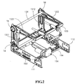
- the foldable car seat constructed in accordance with the present invention includes a base frame 11 and a back frame 13 foldable relative to the base frame 11 with the assistance of a first folding device 14 which is sandwiched between the base frame 11 and bottom of the back frame 13.
- the base frame 11 has a first side plate 111, a second side plate 112 oppositely and horizontally located relative to the first side plate 111 and a first connection rod 113 securely connected to a distal end of both the first side plate 111 and the second side plate 112 to respectively secure relative locations of the first side plate 111 and the second side plate 112.
- a support frame 114 is securely provided between the first side plate 111 and the second side plate 112 to support thereon a driver 154.
- the driver 154 maybe hydraulically or electrically activated piston.
- the back frame 13 is composed of a first support 131 foldably connected to a distal end of the base frame 11 and a second support 132 foldably connected to a distal end of the first support 131.
- the first support 131 consists of a pair of oppositely located first support frames 1311 and the second support 132 consists of a pair of oppositely located second support frames 1312.
- the first side plate 111 is made of a steel or iron having a bending stress larger than 200 Mpa, or a nylon material with or larger than 25% fiber glass, or Polyamide (PA)+Acrylonitrile Butadiene Styrene (ABS) compound material, or a carbonated fiber material or an alloy of aluminum and magnesium, or a titanium alloy or a magnesium alloy.
- PA Polyamide
- ABS Advanced Chemical Synchronization
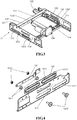
- a sliding frame 15 is provided inside the base frame 11 and has a first slider 151 slidably connected to an inside of the first side plate 111 and a second slider 152 slidably connected to an inside of the second side plate 112.
- Both the first slider 151 and the second slider 152 are, preferably, elongate in shape and have substantially the same structure.
- the following description will focus on the detailed structure of the first slider 151 as well as the relationship between the first slider 151 and the first side plate 111 of the base frame 11. It is appreciated that the first side plate 111 defines there through first bores 1111, preferably elongated in shape.
- the first slider 151 includes a body, a pair of first stops 1511 securely mounted on or attached to a side face of the body and respectively having a centrally defined through hole (not numbered), a pair of bolts 1512 extendable through the first bores 1111 of the first side plate 111 of the base frame 11 and a pair of nuts 1513 securely and threadingly attached to the bolts 1512 after the pair of bolts 1512 are extended through the first bores 1111, the centrally defined through hole of the first stops 1511 and the body.
- the first slider 151 is still able to slide relative to the first side plate 111 with the assistance of the pair of first stops 1511 as well as the bolts 1512 within the first bores 1111 to limit extent of movement of the first slider 151 relative to the first side plate 111.
- a pad frame 161 is sandwiched between the first side plate 111 and the first slider 151.
- the pad frame 161 has a pair of first through holes 1611 defined there through to structurally correspond that of the first bores 1111 of the first side plate 111 to allow extension of the pair of bolts 1512 and a flange 1611 circumferential formed around a periphery defining each of the first through holes 1611 so that after the pad frame 161 is sandwiched between the first slider 151 and the first side plate 111, the friction between the first slider 151 and the first side plate 111 is greatly reduced.
- a second slider 152 is provided to an inside of the second side plate 112 and with the help of second stops 1521, extent of the sliding movement of the second slider 152 relative to the second side plate 112 is limited.
- a second connection rod 153 is provided to firmly connect to distal ends of both of the first slider 151 and the second slider 152 so that both the first slider 151 and the second slider 152 are able to move simultaneously.
- a push rod 1541 a free end of which is extendable from the driver 152 and securely connected to the second connection rod 153 such that the sliding frame 15 is able to move based on the extension of the push rod 1541.
- an adapter 12 is provided to the sliding frame 15.
- the adapter 12 includes a first adapting rod 121 securely connected to the first slider 151 and a second adapting rod 152 securely connected to the second slider 152.
- each distal end of the second connection rod 153 has a circumferential cutout 1531 and an extension 1532, preferably a threaded extension, integrally extended from the distal free end of the circumferential cutout 1531.
- it is still using the first adapting rod 121 for example.
- a distal free end of the first adapting rod 121 has a connection plate 1210 integrally formed and extended out there from.
- the connection plate 1210 has a hole 1211 defined through the connection plate 1210 and structurally adapted to the shape of the circumferential cutout 1531 of the second connection rod 153 so that after the extension 1532 of the second connection rod 153 extends through a portion of the first slider 151 and the hole 1211 of the first adapting rod 121, the circumferential cutout 1531 is snugly fitted inside the hole 1211 of the first adapting rod 121 and thus after a nut is used to secure engagement between the second adapting rod 121 and the second connection rod 153, the adapter 12 is able to move while the second connection rod 153 is moved by the power of the push rod 1541 of the driver 154.
- the base frame 11 is able to move relative to the car seat to accomplish the purpose of adjusting the foldable car seat relative to the vehicle seat.
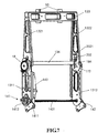
- a first folding device 14 is provided to both the base frame 11 and the back frame 13 and has a first adjuster 141 sandwiched between the first side plate 111 and a first support frame 1311 a second adjuster 142 sandwiched between the second support frame 1312 and the second side plate 112. Still, for brevity and to avoid any misunderstanding resulted from description repetition, only the first adjuster141 is described and the second adjuster 142 will not be described as fully as that of the first adjuster 141.
- the first adjuster 141 is composed of a first adjusting plate 1411 securely attached to a side face of the first side plate 111 and a second adjusting plate 1412 securely attached to a side face of the first support frame 1311.
- a motor 143 preferably a step motor, is securely attached to an inner side face of the first support frame 1311 and has a driving rod 1431 firmly connecting an inner side face of each of the second adjusting plate 1412 of the first adjuster 141 and of the second adjuster 142 to drive the second adjusting plate 1412 of the first adjuster 141 and the second adjusting plate of the second adjuster 142 to rotate relative to the first adjusting plate 1411 of the first adjuster 141 and the first adjusting plate of the second adjuster 142 so that both of the first support frame 1311 and the second support frame 1312 are able to fold (rotate or pivot or any equivalent movement) relative to the first side plate 111 and the second side plate 112 of the base frame 11.
- the back frame 13 is foldable relative to the base 11.
- the first adjusting plate 1411 may be provided with a planetary gear (not numbered) and the second adjusting plate 1412 may be provided with a sun gear (not numbered) mated with the planetary gear of the first adjusting plate 1411 such that when the motor 143 is powered to drive the driving rod 1431 to rotate, which produces the driving power to the second adjusting plate 1412 as well as the sun gear. As result, the back frame 13 is folded as required.
- a second folding device 18 between the first support 131 and the second support 132.
- the second folding device 18 is sandwiched between the first support frame 1311 and the third support frame 1321 and between the second support frame 1312 and the forth support frame 1322.
- the second folding device 18 attached between the first support frame 1311 and the third support frame 1321 is described.
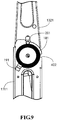
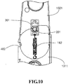
- the second folding device 18 includes a first cutout 401 defined in a top periphery of the first support frame 1311, a second cutout 402 defined in a side periphery of the first support frame 1311 and a positioning stop 191 formed on a side face of the first support frame 1311. Furthermore, it is to be noted that the second folding device 18 also has a first joint 171 (a second joint 172 is shown especially in Fig.
- first spring 181 of the second folding device 18 is provided on the outside of the first support frame 1311.
- a second spring 182 (184 is provided between the second support frame 1312 and the fourth support frame 1322), preferably a leaf spring, is provided on the inside of the first support frame 1311 and has a first end securely attached to an inner side face of the first support frame 1311 and a second end provided with a limit 201 (a second limit 202 is provided to the second spring 184 between the second support frame 1312 and the fourth support frame 1322) formed thereon.
- a limit hole 301 is defined through a side face of the third support frame 1321 so that the limit 201 is able to slide within the limit hole 301.
- a lifter 2011 may be provided to the limit 201.
- the lifter 2011 may be integrally formed on the limit 201 or may be detachably yet firmly connected to the limit 201.
- the technique involved to form the lifter 2011 on the limit 201 or to detachably yet firmly connect the lifter 2011 to the limit 201 is well known in the art and no detailed description thereof is provided for clarity and concise.
- a pillow mount 50 is provided on top of the foldable car seat and has a top beam 133 mounted on free ends of both the third support frame 1321 and the fourth support frame 1322 and a lower beam 134 mounted at a middle portion of both the third support frame 1321 and the fourth support frame 1322.
Landscapes
- Engineering & Computer Science (AREA)
- Aviation & Aerospace Engineering (AREA)
- Transportation (AREA)
- Mechanical Engineering (AREA)
- Health & Medical Sciences (AREA)
- Child & Adolescent Psychology (AREA)
- General Health & Medical Sciences (AREA)
- Seats For Vehicles (AREA)
Claims (6)
- Klappbarer Autositz, der dafür ausgelegt ist, sich mit einem Fahrzeugsitz zu verbinden, und Folgendes umfasst:einen Grundrahmen (11), an dem ein Mitnehmer (154) fest montiert ist,einen Gleitrahmen (15), der mit dem Mitnehmer (154) in Wirkverbindung steht, verschiebbar an einer Innenseite des Grundrahmens (11) angebracht ist und einen Adapter (12) aufweist, der fest an einem freien Ende des Gleitrahmens (15) angebracht ist, um sich an den Fahrzeugsitz anzupassen, so dass sich der Grundrahmen (11) aufgrund der Leistung von dem Motor (154) relativ zu dem Gleitrahmen (15) bewegen kann, undein Rückenrahmen (13), der klappbar mit dem Grundrahmen (11) verbunden ist und ein Paar unterer Stützrahmen (131), die klappbar mit freien Enden des Grundrahmens (11) über eine erste Klappvorrichtung (141) verbunden sind, und ein Paar oberer Stützrahmen (132) umfasst, die klappbar mit freien Enden des Paars unterer Stützrahmen (131) über eine zweite Klappvorrichtung (142) verbunden sind, um zu ermöglichen, dass sich das Paar unterer Stützrahmen (131) relativ zu dem Grundrahmen (11) und das Paar oberer Stützrahmen (132) relativ zu dem Paar unterer Stützrahmen (131) klappt,wobei der Gleitrahmen (15) einen ersten Gleiter (151), der verschiebbar an einer Innenseite des Grundrahmens (11) angebracht ist, einen zweiten Gleiter (152), der dem ersten Gleiter (151) gegenüberliegend angeordnet und verschiebbar an der Innenseite des Grundrahmens (11) angebracht ist, und eine Verbindungsstange (113) aufweist, die fest mit dem ersten Gleiter (151) und dem zweiten Gleiter (152) verbunden ist und den Motor (154) hat, der fest daran befestigt ist, so dass die Verbindungsstange (113), der erste Gleiter (151) und der zweite Gleiter (152) aufgrund des Mitnehmers (154) relativ zu dem Grundrahmen (11) bewegt werden,wobei ein Unterlagerahmen (161) zwischen dem ersten Gleiter (151) und dem Grundrahmen (11) und zwischen dem zweiten Gleiter (152) und dem Grundrahmen (11) angeordnet ist und einen daran ausgebildeten Flansch (16111) aufweist, um eine übermäßige Reibung dazwischen zu vermeiden,wobei der Grundrahmen (11) eine erste Seitenplatte (111), eine zweite Seitenplatte (112), die der ersten Seitenplatte (111) gegenüberliegend angeordnet ist, und eine Verbindungsstange (113) umfasst, die zwischen der ersten Seitenplatte (111) und der zweiten Seitenplatte (112) angeordnet ist, um Positionen der ersten Seitenplatte (111) und der zweiten Seitenplatte (112) zu fixieren,wobei eine Bohrung (1111) durch die Seitenfläche der ersten Seitenplatte (111) und der zweiten Seitenplatte (112) hindurch ausgebildet ist, um darin beweglich mindestens einen Anschlag (1511) aufzunehmen, der fest an einer Seitenfläche des ersten Schiebers (151) und des zweiten Schiebers (152) befestigt ist, so dass das Ausmaß der Bewegung von sowohl dem ersten Schieber (151) als auch dem zweiten Schieber (152) begrenzt ist,wobei der Rückenrahmen (13) einen ersten Stützrahmen (1311), der klappbar mit dem distalen Ende der ersten Seitenplatte (111) verbunden ist, und einen zweiten Stützrahmen (1312), der dem ersten Stützrahmen (1311) gegenüberliegend angeordnet und klappbar mit dem distalen Ende der zweiten Seitenplatte (112) verbunden ist, umfasst, wobei die erste Klappvorrichtung (141) zwischen dem ersten Stützrahmen (1311) und dem distalen Ende der ersten Seitenplatte (111) und zwischen dem zweiten Stützrahmen (1312) und dem distalen Ende der zweiten Seitenplatte (112) angeordnet ist, so dass sowohl der erste Stützrahmen (1311) als auch der zweite Stützrahmen (1312) aufgrund der Verbindungsstange (113) gleichzeitig relativ zu dem Grundrahmen (11) zusammenklappen können.
- Klappbarer Autositz nach Anspruch 1, wobei die erste Klappvorrichtung (141) eine erste Einstellplatte (1411), die fest an der ersten Seitenplatte (111) befestigt ist, eine zweite Einstellplatte (1412), die fest an dem ersten Stützrahmen (1311) befestigt ist, und einen Motor umfasst, der fest an einer Innenseite des ersten Stützrahmens (1311) angebracht ist, um die zweite Einstellplatte (1412) derart anzutreiben, dass sie relativ zu der ersten Einstellplatte (1411) schwenkt, so dass der erste Stützrahmen (1311) relativ zu der ersten Seitenplatte (111) klappbar ist.
- Klappbarer Autositz nach Anspruch 2, umfassend ferner eine Antriebsstange (1431), die den ersten Stützrahmen (1311) fest mit dem zweiten Stützrahmen (1312) verbindet, um zu ermöglichen, dass der erste Stützrahmen (1311) zusammen mit dem zweiten Stützrahmen (1312) relativ zu dem Grundrahmen (111) schwenkt.
- Klappbarer Autositz nach Anspruch 2, umfassend ferner einen dritten Stützrahmen (1321), der klappbar mit dem ersten Stützrahmen (1311) verbunden ist, und einen vierten Stützrahmen (1322), der klappbar mit dem zweiten Stützrahmen (1312) verbunden ist, wobei die zweite Klappvorrichtung (18) zwischen dem ersten Stützrahmen (1311) und dem dritten Stützrahmen (1321) und zwischen dem zweiten Stützrahmen (1312) und dem vierten Stützrahmen (1322) angeordnet ist, um jeweils dem dritten Stützrahmen (1321) und dem vierten Stützrahmen (1322) zu ermöglichen, relativ zu dem ersten Stützrahmen (1311) bzw. dem zweiten Stützrahmen (1312) zusammenzuklappen,
wobei der dritte Stützrahmen (1321) und der vierte Stützrahmen (1322) selektiv zwischen einer ersten Position, in der dritte Stützrahmen (1321) und der vierte Stützrahmen (1322) parallel zu dem ersten Stützrahmen (1311) und dem zweiten Stützrahmen (1312) angeordnet sind, und einer zweiten Position, in der dritte Stützrahmen (1321) und der vierte Stützrahmen (1322) senkrecht relativ zu dem ersten Stützrahmen (1311) und dem zweiten Stützrahmen (1312) angeordnet sind, positioniert werden,
wobei die zweite Klappvorrichtung (18) ein Gelenk (171, 172), das jeweils zwischen dem ersten Stützrahmen (1311) und dem dritten Stützrahmen (1321) bzw. zwischen dem zweiten Stützrahmen (1312) und dem vierten Stützrahmen (1322) eingeführt ist, um zu ermöglichen, dass der dritte Stützrahmen (1321) relativ zu dem ersten Stützrahmen (1311) und der vierte Stützrahmen (1322) relativ zu dem zweiten Stützrahmen (1312) schwenken kann, und eine erste Feder (181) umfasst, die ein erstes Ende, das sicher in einem freien Ende des Gelenks (171, 172) arretiert ist, und ein zweites Ende, das fest an einer Seitenfläche des ersten Stützrahmens (1311) angebracht ist, aufweist, so dass, wenn der dritte Stützrahmen (1321) und der vierte Stützrahmen (1322) parallel zu dem ersten Stützrahmen (1311) und dem zweiten Stützrahmen (1312) angeordnet sind, die erste Feder (181) spannungsfrei ist und, wenn der dritte Stützrahmen (1321) und der vierte Stützrahmen (1322) senkrecht relativ zu dem ersten Stützrahmen (1311) und dem zweiten Stützrahmen (1312) angeordnet sind, die erste Feder (181) gespannt ist. - Klappbarer Autositz nach Anspruch 4, wobei die zweite Klappvorrichtung (18) ferner eine erste Aussparung (401), die in einem oberen Umfang des ersten Stützrahmens (1311) und des zweiten Stützrahmens (1312) definiert ist, eine zweite Aussparung (402), die in einem Seitenumfang des ersten Stützrahmens (1311) und des zweiten Stützrahmens (1312) definiert ist, und ein Begrenzelement umfasst, das selektiv in der ersten Aussparung (401) und der zweiten Aussparung (402) angeordnet ist, um jeweils den dritten Stützrahmen (1321) und den vierten Stützrahmen (1322) so zu positionieren, dass sie parallel oder vertikal relativ zu dem ersten Stützrahmen (1311) bzw. dem zweiten Stützrahmen (1312) angeordnet sind,
wobei die zweite Klappvorrichtung (18) ferner eine zweite Feder (182) umfasst, die ein erstes Ende, das fest jeweils an einer inneren Seitenfläche des dritten Stützrahmens (1321) und des vierten Stützrahmens (1322) befestigt ist, und ein zweites Ende aufweist, das fest an dem Begrenzelement (201) angebracht ist, um zu ermöglichen, dass das Begrenzelement (201) nach Bewegen des Begrenzelements (201) zurückgezogen wird. - Klappbarer Autositz nach Anspruch 1, wobei die erste Seitenplatte (111) aus einem Material hergestellt ist, das aus der Gruppe ausgewählt ist, die aus Stahl oder Eisen mit einer Biegespannung von größer als 200 Mpa, einem Nylonmaterial mit einem Faserglasgehalt von 25% oder mehr, Polyamid (PA) + Acrylnitril-Butadien-Styrol (ABS)-Verbundmaterial, einem karbonisierten Fasermaterial, einer Legierung aus Aluminium und Magnesium, einer Titanlegierung und einer Magnesiumlegierung besteht.
Applications Claiming Priority (2)
| Application Number | Priority Date | Filing Date | Title |
|---|---|---|---|
| CN201610194414.1A CN107284311B (zh) | 2016-03-30 | 2016-03-30 | 折叠式电动儿童安全座椅 |
| PCT/CN2016/082592 WO2017166395A1 (zh) | 2016-03-30 | 2016-05-19 | 折叠式电动儿童安全座椅 |
Publications (3)
| Publication Number | Publication Date |
|---|---|
| EP3248835A1 EP3248835A1 (de) | 2017-11-29 |
| EP3248835A4 EP3248835A4 (de) | 2018-03-21 |
| EP3248835B1 true EP3248835B1 (de) | 2021-03-10 |
Family
ID=59962515
Family Applications (1)
| Application Number | Title | Priority Date | Filing Date |
|---|---|---|---|
| EP16754159.8A Active EP3248835B1 (de) | 2016-03-30 | 2016-05-19 | Faltbarer elektrischer kindersicherheitssitz |
Country Status (7)
| Country | Link |
|---|---|
| US (1) | US10023080B2 (de) |
| EP (1) | EP3248835B1 (de) |
| JP (1) | JP6449900B2 (de) |
| KR (1) | KR101956688B1 (de) |
| CN (1) | CN107284311B (de) |
| ES (1) | ES2871014T3 (de) |
| WO (1) | WO2017166395A1 (de) |
Families Citing this family (8)
| Publication number | Priority date | Publication date | Assignee | Title |
|---|---|---|---|---|
| CN109130977B (zh) * | 2017-01-06 | 2020-12-01 | 上海沃雨电子科技有限公司 | 儿童安全座椅isofix与靠背联动调节的系统及方法 |
| US11001178B2 (en) * | 2017-03-27 | 2021-05-11 | Ts Tech Co., Ltd. | Conveyance seat |
| CN107791906A (zh) * | 2017-10-24 | 2018-03-13 | 上海沃雨电子科技有限公司 | 儿童安全座椅骨架及其拆装isofix的方法 |
| CN108422904A (zh) * | 2018-05-15 | 2018-08-21 | 上海沃雨电子科技有限公司 | 儿童安全座椅折叠机构 |
| CN114475377B (zh) * | 2021-12-27 | 2023-05-09 | 东风汽车有限公司东风日产乘用车公司 | 车辆座椅 |
| CN114393373B (zh) * | 2022-01-06 | 2023-09-05 | 无锡曙光精密工业有限公司 | 一种折叠式儿童座椅制造工艺及其折叠式儿童座椅 |
| CN114290967B (zh) * | 2022-01-10 | 2023-07-04 | 浙江吉利控股集团有限公司 | 座椅骨架、座椅及车辆 |
| KR102784551B1 (ko) | 2022-12-13 | 2025-03-21 | 현대트랜시스 주식회사 | 자동차용 시트백 각도 조절장치 |
Family Cites Families (32)
| Publication number | Priority date | Publication date | Assignee | Title |
|---|---|---|---|---|
| JPS5818830U (ja) * | 1981-07-30 | 1983-02-05 | 株式会社 タチエス | 車両用座席 |
| DE19906547B4 (de) * | 1999-02-17 | 2004-03-25 | Innovint Einrichtungs Gmbh | Kindersitz zur mobilen Verwendung in einem Flugzeug |
| US6513876B1 (en) * | 2000-11-17 | 2003-02-04 | Gayle D. Agler | Multiple function boat seat |
| FR2829439B1 (fr) * | 2001-09-07 | 2004-01-16 | Faurecia Sieges Automobile | Pietement de siege de vehicule, siege comportant un tel pietement et ensemble d'assise comportant un tel siege |
| US6739661B1 (en) * | 2002-07-15 | 2004-05-25 | David N. Dukes | Pivotable reclining child safety car seat |
| DE10317239A1 (de) * | 2003-04-10 | 2004-10-28 | Brose Fahrzeugteile Gmbh & Co. Kommanditgesellschaft, Coburg | Sitzlängsführung für einen Kraftfahrzeugsitz |
| FR2856963B1 (fr) * | 2003-07-03 | 2006-09-01 | Antolin Grupo Ing Sa | Siege de vehicule automobile |
| JP2007528315A (ja) * | 2004-02-23 | 2007-10-11 | トラベラー イノヴェイションズ リミテッド | 折りたたみ式携帯型チャイルド安全シート |
| JP4649864B2 (ja) * | 2004-04-15 | 2011-03-16 | マツダ株式会社 | 車両用シート装置システム |
| US8282165B2 (en) * | 2004-04-28 | 2012-10-09 | Recaro Child Safety Gmbh & Co. Kg | Reboard system |
| ATE442277T1 (de) * | 2005-02-17 | 2009-09-15 | Pesach Gidon | Auto-babysitz |
| ES1063434Y (es) * | 2006-07-14 | 2007-01-16 | Jane Sa | Base para el acoplamiento de asientos infantiles en automoviles |
| US7547066B2 (en) * | 2007-04-20 | 2009-06-16 | Cosco Management, Inc. | Juvenile vehicle seat with forward-folding headrest and rearward-folding foundation |
| EP2347929B1 (de) * | 2008-10-20 | 2016-04-13 | NHK Spring Co., Ltd. | Sitzlehnenrahmenstruktur eines Sitzes für Fahrzeug und Sitz für Fahrzeug mit Sitzlehnenrahmenstruktur |
| DE102009013163A1 (de) * | 2009-03-10 | 2010-09-16 | Concord Gmbh | Kindersitz für Kraftfahrzeuge |
| US8262161B2 (en) * | 2010-05-04 | 2012-09-11 | Cosco Management, Inc. | Child restraint for vehicle |
| US8251446B1 (en) * | 2010-12-07 | 2012-08-28 | Guerrido Natalie R | Articulated child seat apparatus |
| US8646840B2 (en) * | 2010-12-22 | 2014-02-11 | Nissan North America, Inc. | Vehicle seat assembly |
| JP5788216B2 (ja) * | 2011-05-13 | 2015-09-30 | 日本発條株式会社 | 車両用シートのクッションシートフレーム構造および該構造を有する車両用シート |
| JP5814672B2 (ja) * | 2011-07-19 | 2015-11-17 | 株式会社カーメイト | チャイルドシート |
| CN203739691U (zh) * | 2013-12-23 | 2014-07-30 | 好孩子儿童用品有限公司 | 儿童汽车安全座椅 |
| JP6328228B2 (ja) * | 2014-03-31 | 2018-05-23 | コンビ株式会社 | チャイルドシート |
| JP6621403B2 (ja) * | 2014-05-12 | 2019-12-18 | 株式会社デルタツーリング | 座席構造 |
| CN203920495U (zh) * | 2014-07-08 | 2014-11-05 | 宁波贝安宝儿童用品有限公司 | 一种便携式多功能儿童安全座椅 |
| US20160059745A1 (en) * | 2014-08-30 | 2016-03-03 | Christopher Carl Whitcombe | Automatic Child Car Seat Safety Harness Tightening and Indication Systems |
| CN104210392B (zh) * | 2014-09-19 | 2016-12-07 | 杭州大器婴童用品有限公司 | 一种儿童安全座椅 |
| CN104608658A (zh) * | 2015-01-07 | 2015-05-13 | 东风李尔汽车座椅有限公司 | 布置有三点式安全带可前翻和侧翻的汽车座椅骨架 |
| CN104709128B (zh) * | 2015-01-22 | 2017-03-15 | 上海延锋江森座椅有限公司 | 一种带有吸能结构的车辆座椅 |
| JP3199855U (ja) * | 2015-03-13 | 2015-09-10 | グッドベイビー チャイルド プロダクツ カンパニー リミテッド | 折り畳み式チャイルドシート |
| CN204978314U (zh) * | 2015-08-12 | 2016-01-20 | 上海初德电气有限公司 | 一种汽车座椅的isofix电动伸缩装置 |
| CN205059325U (zh) * | 2015-08-26 | 2016-03-02 | 常州安宝宝儿童座椅有限公司 | 儿童安全座椅isofix连接装置 |
| DE102016209007B4 (de) * | 2016-01-28 | 2021-09-16 | Adient Luxembourg Holding S.À R.L. | Fahrzeugsitz mit einem Easy-Entry-Modul |
-
2016
- 2016-03-30 CN CN201610194414.1A patent/CN107284311B/zh active Active
- 2016-05-19 EP EP16754159.8A patent/EP3248835B1/de active Active
- 2016-05-19 WO PCT/CN2016/082592 patent/WO2017166395A1/zh not_active Ceased
- 2016-05-19 ES ES16754159T patent/ES2871014T3/es active Active
- 2016-05-19 KR KR1020177026742A patent/KR101956688B1/ko not_active Expired - Fee Related
- 2016-05-19 JP JP2016554729A patent/JP6449900B2/ja not_active Expired - Fee Related
- 2016-05-19 US US15/122,593 patent/US10023080B2/en active Active
Non-Patent Citations (1)
| Title |
|---|
| None * |
Also Published As
| Publication number | Publication date |
|---|---|
| KR101956688B1 (ko) | 2019-03-11 |
| EP3248835A1 (de) | 2017-11-29 |
| ES2871014T3 (es) | 2021-10-28 |
| WO2017166395A1 (zh) | 2017-10-05 |
| US20180111515A1 (en) | 2018-04-26 |
| CN107284311A (zh) | 2017-10-24 |
| US10023080B2 (en) | 2018-07-17 |
| CN107284311B (zh) | 2020-06-23 |
| JP6449900B2 (ja) | 2019-01-09 |
| KR20170121229A (ko) | 2017-11-01 |
| EP3248835A4 (de) | 2018-03-21 |
| JP2018514429A (ja) | 2018-06-07 |
Similar Documents
| Publication | Publication Date | Title |
|---|---|---|
| EP3248835B1 (de) | Faltbarer elektrischer kindersicherheitssitz | |
| EP3446919B1 (de) | Manueller faltbarer kindersitz | |
| JP4428666B2 (ja) | 乗員を中心に位置させる人間工学的支持装置および方法 | |
| US9150130B2 (en) | Portable headrest | |
| US8061777B2 (en) | System for seat-actuated head rest extension and retraction | |
| JP2016008046A (ja) | 調整可能なテーブル及び後部座席 | |
| JP5921767B2 (ja) | 車両座席の垂直調整用の座席調整装置 | |
| JP5164242B2 (ja) | 子供用座席及び伸縮自在に調節可能な足支持具 | |
| CN206374601U (zh) | 一种双向网格式手动腰托 | |
| CN104085328A (zh) | 活动扶手汽车座椅 | |
| CN212098537U (zh) | 肩部调节装置、座椅及车辆 | |
| CN210284003U (zh) | 车辆扶手结构和车辆 | |
| US10946916B1 (en) | Assisted spring seat height optimization lift | |
| CN217100274U (zh) | 一种减震效果好的电动自行车后座 | |
| CN109080510B (zh) | 一种座椅靠背角度调节装置 | |
| CN106132771B (zh) | 便携式头靠 | |
| KR20190087852A (ko) | 4륜 실버캐리지 | |
| CN206938515U (zh) | 用于车辆的座椅骨架及具有其的座椅 | |
| CN119564455A (zh) | 一种可调节靠背高度的自重力脊椎防护椅 | |
| KR20030017727A (ko) | 자동차용 시트 | |
| KR101300268B1 (ko) | 우산꽂이를 갖는 휠체어 | |
| JP3099856U (ja) | 両用運搬車 | |
| JP2005067329A (ja) | ヘッドレスト自動格納調整装置 | |
| KR20190105700A (ko) | 자동차 시트용 헤드레스트 | |
| JPH10181405A (ja) | シートサスペンション装置 |
Legal Events
| Date | Code | Title | Description |
|---|---|---|---|
| STAA | Information on the status of an ep patent application or granted ep patent |
Free format text: STATUS: UNKNOWN |
|
| STAA | Information on the status of an ep patent application or granted ep patent |
Free format text: STATUS: THE INTERNATIONAL PUBLICATION HAS BEEN MADE |
|
| PUAI | Public reference made under article 153(3) epc to a published international application that has entered the european phase |
Free format text: ORIGINAL CODE: 0009012 |
|
| STAA | Information on the status of an ep patent application or granted ep patent |
Free format text: STATUS: REQUEST FOR EXAMINATION WAS MADE |
|
| 17P | Request for examination filed |
Effective date: 20160831 |
|
| AK | Designated contracting states |
Kind code of ref document: A1 Designated state(s): AL AT BE BG CH CY CZ DE DK EE ES FI FR GB GR HR HU IE IS IT LI LT LU LV MC MK MT NL NO PL PT RO RS SE SI SK SM TR |
|
| AX | Request for extension of the european patent |
Extension state: BA ME |
|
| A4 | Supplementary search report drawn up and despatched |
Effective date: 20180220 |
|
| RIC1 | Information provided on ipc code assigned before grant |
Ipc: B60N 2/68 20060101AFI20180214BHEP Ipc: B60N 2/28 20060101ALI20180214BHEP Ipc: B60N 2/00 20060101ALI20180214BHEP |
|
| DAV | Request for validation of the european patent (deleted) | ||
| DAX | Request for extension of the european patent (deleted) | ||
| GRAP | Despatch of communication of intention to grant a patent |
Free format text: ORIGINAL CODE: EPIDOSNIGR1 |
|
| STAA | Information on the status of an ep patent application or granted ep patent |
Free format text: STATUS: GRANT OF PATENT IS INTENDED |
|
| INTG | Intention to grant announced |
Effective date: 20201106 |
|
| GRAS | Grant fee paid |
Free format text: ORIGINAL CODE: EPIDOSNIGR3 |
|
| GRAA | (expected) grant |
Free format text: ORIGINAL CODE: 0009210 |
|
| STAA | Information on the status of an ep patent application or granted ep patent |
Free format text: STATUS: THE PATENT HAS BEEN GRANTED |
|
| AK | Designated contracting states |
Kind code of ref document: B1 Designated state(s): AL AT BE BG CH CY CZ DE DK EE ES FI FR GB GR HR HU IE IS IT LI LT LU LV MC MK MT NL NO PL PT RO RS SE SI SK SM TR |
|
| REG | Reference to a national code |
Ref country code: GB Ref legal event code: FG4D |
|
| REG | Reference to a national code |
Ref country code: AT Ref legal event code: REF Ref document number: 1369465 Country of ref document: AT Kind code of ref document: T Effective date: 20210315 Ref country code: CH Ref legal event code: EP |
|
| REG | Reference to a national code |
Ref country code: IE Ref legal event code: FG4D |
|
| REG | Reference to a national code |
Ref country code: DE Ref legal event code: R096 Ref document number: 602016054029 Country of ref document: DE |
|
| REG | Reference to a national code |
Ref country code: LT Ref legal event code: MG9D |
|
| PG25 | Lapsed in a contracting state [announced via postgrant information from national office to epo] |
Ref country code: NO Free format text: LAPSE BECAUSE OF FAILURE TO SUBMIT A TRANSLATION OF THE DESCRIPTION OR TO PAY THE FEE WITHIN THE PRESCRIBED TIME-LIMIT Effective date: 20210610 Ref country code: FI Free format text: LAPSE BECAUSE OF FAILURE TO SUBMIT A TRANSLATION OF THE DESCRIPTION OR TO PAY THE FEE WITHIN THE PRESCRIBED TIME-LIMIT Effective date: 20210310 Ref country code: GR Free format text: LAPSE BECAUSE OF FAILURE TO SUBMIT A TRANSLATION OF THE DESCRIPTION OR TO PAY THE FEE WITHIN THE PRESCRIBED TIME-LIMIT Effective date: 20210611 Ref country code: HR Free format text: LAPSE BECAUSE OF FAILURE TO SUBMIT A TRANSLATION OF THE DESCRIPTION OR TO PAY THE FEE WITHIN THE PRESCRIBED TIME-LIMIT Effective date: 20210310 Ref country code: LT Free format text: LAPSE BECAUSE OF FAILURE TO SUBMIT A TRANSLATION OF THE DESCRIPTION OR TO PAY THE FEE WITHIN THE PRESCRIBED TIME-LIMIT Effective date: 20210310 Ref country code: BG Free format text: LAPSE BECAUSE OF FAILURE TO SUBMIT A TRANSLATION OF THE DESCRIPTION OR TO PAY THE FEE WITHIN THE PRESCRIBED TIME-LIMIT Effective date: 20210610 |
|
| REG | Reference to a national code |
Ref country code: AT Ref legal event code: MK05 Ref document number: 1369465 Country of ref document: AT Kind code of ref document: T Effective date: 20210310 |
|
| REG | Reference to a national code |
Ref country code: NL Ref legal event code: MP Effective date: 20210310 |
|
| PG25 | Lapsed in a contracting state [announced via postgrant information from national office to epo] |
Ref country code: LV Free format text: LAPSE BECAUSE OF FAILURE TO SUBMIT A TRANSLATION OF THE DESCRIPTION OR TO PAY THE FEE WITHIN THE PRESCRIBED TIME-LIMIT Effective date: 20210310 Ref country code: RS Free format text: LAPSE BECAUSE OF FAILURE TO SUBMIT A TRANSLATION OF THE DESCRIPTION OR TO PAY THE FEE WITHIN THE PRESCRIBED TIME-LIMIT Effective date: 20210310 Ref country code: SE Free format text: LAPSE BECAUSE OF FAILURE TO SUBMIT A TRANSLATION OF THE DESCRIPTION OR TO PAY THE FEE WITHIN THE PRESCRIBED TIME-LIMIT Effective date: 20210310 |
|
| PG25 | Lapsed in a contracting state [announced via postgrant information from national office to epo] |
Ref country code: NL Free format text: LAPSE BECAUSE OF FAILURE TO SUBMIT A TRANSLATION OF THE DESCRIPTION OR TO PAY THE FEE WITHIN THE PRESCRIBED TIME-LIMIT Effective date: 20210310 |
|
| REG | Reference to a national code |
Ref country code: ES Ref legal event code: FG2A Ref document number: 2871014 Country of ref document: ES Kind code of ref document: T3 Effective date: 20211028 |
|
| PG25 | Lapsed in a contracting state [announced via postgrant information from national office to epo] |
Ref country code: AT Free format text: LAPSE BECAUSE OF FAILURE TO SUBMIT A TRANSLATION OF THE DESCRIPTION OR TO PAY THE FEE WITHIN THE PRESCRIBED TIME-LIMIT Effective date: 20210310 Ref country code: SM Free format text: LAPSE BECAUSE OF FAILURE TO SUBMIT A TRANSLATION OF THE DESCRIPTION OR TO PAY THE FEE WITHIN THE PRESCRIBED TIME-LIMIT Effective date: 20210310 Ref country code: EE Free format text: LAPSE BECAUSE OF FAILURE TO SUBMIT A TRANSLATION OF THE DESCRIPTION OR TO PAY THE FEE WITHIN THE PRESCRIBED TIME-LIMIT Effective date: 20210310 Ref country code: CZ Free format text: LAPSE BECAUSE OF FAILURE TO SUBMIT A TRANSLATION OF THE DESCRIPTION OR TO PAY THE FEE WITHIN THE PRESCRIBED TIME-LIMIT Effective date: 20210310 |
|
| PG25 | Lapsed in a contracting state [announced via postgrant information from national office to epo] |
Ref country code: RO Free format text: LAPSE BECAUSE OF FAILURE TO SUBMIT A TRANSLATION OF THE DESCRIPTION OR TO PAY THE FEE WITHIN THE PRESCRIBED TIME-LIMIT Effective date: 20210310 Ref country code: SK Free format text: LAPSE BECAUSE OF FAILURE TO SUBMIT A TRANSLATION OF THE DESCRIPTION OR TO PAY THE FEE WITHIN THE PRESCRIBED TIME-LIMIT Effective date: 20210310 Ref country code: PL Free format text: LAPSE BECAUSE OF FAILURE TO SUBMIT A TRANSLATION OF THE DESCRIPTION OR TO PAY THE FEE WITHIN THE PRESCRIBED TIME-LIMIT Effective date: 20210310 Ref country code: PT Free format text: LAPSE BECAUSE OF FAILURE TO SUBMIT A TRANSLATION OF THE DESCRIPTION OR TO PAY THE FEE WITHIN THE PRESCRIBED TIME-LIMIT Effective date: 20210712 Ref country code: IS Free format text: LAPSE BECAUSE OF FAILURE TO SUBMIT A TRANSLATION OF THE DESCRIPTION OR TO PAY THE FEE WITHIN THE PRESCRIBED TIME-LIMIT Effective date: 20210710 |
|
| REG | Reference to a national code |
Ref country code: DE Ref legal event code: R097 Ref document number: 602016054029 Country of ref document: DE |
|
| REG | Reference to a national code |
Ref country code: CH Ref legal event code: PL |
|
| PLBE | No opposition filed within time limit |
Free format text: ORIGINAL CODE: 0009261 |
|
| STAA | Information on the status of an ep patent application or granted ep patent |
Free format text: STATUS: NO OPPOSITION FILED WITHIN TIME LIMIT |
|
| PG25 | Lapsed in a contracting state [announced via postgrant information from national office to epo] |
Ref country code: DK Free format text: LAPSE BECAUSE OF FAILURE TO SUBMIT A TRANSLATION OF THE DESCRIPTION OR TO PAY THE FEE WITHIN THE PRESCRIBED TIME-LIMIT Effective date: 20210310 Ref country code: LU Free format text: LAPSE BECAUSE OF NON-PAYMENT OF DUE FEES Effective date: 20210519 Ref country code: MC Free format text: LAPSE BECAUSE OF FAILURE TO SUBMIT A TRANSLATION OF THE DESCRIPTION OR TO PAY THE FEE WITHIN THE PRESCRIBED TIME-LIMIT Effective date: 20210310 Ref country code: LI Free format text: LAPSE BECAUSE OF NON-PAYMENT OF DUE FEES Effective date: 20210531 Ref country code: AL Free format text: LAPSE BECAUSE OF FAILURE TO SUBMIT A TRANSLATION OF THE DESCRIPTION OR TO PAY THE FEE WITHIN THE PRESCRIBED TIME-LIMIT Effective date: 20210310 Ref country code: CH Free format text: LAPSE BECAUSE OF NON-PAYMENT OF DUE FEES Effective date: 20210531 |
|
| 26N | No opposition filed |
Effective date: 20211213 |
|
| PG25 | Lapsed in a contracting state [announced via postgrant information from national office to epo] |
Ref country code: SI Free format text: LAPSE BECAUSE OF FAILURE TO SUBMIT A TRANSLATION OF THE DESCRIPTION OR TO PAY THE FEE WITHIN THE PRESCRIBED TIME-LIMIT Effective date: 20210310 |
|
| PG25 | Lapsed in a contracting state [announced via postgrant information from national office to epo] |
Ref country code: IE Free format text: LAPSE BECAUSE OF NON-PAYMENT OF DUE FEES Effective date: 20210519 |
|
| PG25 | Lapsed in a contracting state [announced via postgrant information from national office to epo] |
Ref country code: IS Free format text: LAPSE BECAUSE OF FAILURE TO SUBMIT A TRANSLATION OF THE DESCRIPTION OR TO PAY THE FEE WITHIN THE PRESCRIBED TIME-LIMIT Effective date: 20210710 |
|
| PG25 | Lapsed in a contracting state [announced via postgrant information from national office to epo] |
Ref country code: HU Free format text: LAPSE BECAUSE OF FAILURE TO SUBMIT A TRANSLATION OF THE DESCRIPTION OR TO PAY THE FEE WITHIN THE PRESCRIBED TIME-LIMIT; INVALID AB INITIO Effective date: 20160519 |
|
| PG25 | Lapsed in a contracting state [announced via postgrant information from national office to epo] |
Ref country code: CY Free format text: LAPSE BECAUSE OF FAILURE TO SUBMIT A TRANSLATION OF THE DESCRIPTION OR TO PAY THE FEE WITHIN THE PRESCRIBED TIME-LIMIT Effective date: 20210310 |
|
| PGFP | Annual fee paid to national office [announced via postgrant information from national office to epo] |
Ref country code: IT Payment date: 20230515 Year of fee payment: 8 Ref country code: FR Payment date: 20230523 Year of fee payment: 8 Ref country code: ES Payment date: 20230607 Year of fee payment: 8 |
|
| PGFP | Annual fee paid to national office [announced via postgrant information from national office to epo] |
Ref country code: BE Payment date: 20230515 Year of fee payment: 8 |
|
| PGFP | Annual fee paid to national office [announced via postgrant information from national office to epo] |
Ref country code: GB Payment date: 20230519 Year of fee payment: 8 |
|
| PG25 | Lapsed in a contracting state [announced via postgrant information from national office to epo] |
Ref country code: MK Free format text: LAPSE BECAUSE OF FAILURE TO SUBMIT A TRANSLATION OF THE DESCRIPTION OR TO PAY THE FEE WITHIN THE PRESCRIBED TIME-LIMIT Effective date: 20210310 |
|
| PG25 | Lapsed in a contracting state [announced via postgrant information from national office to epo] |
Ref country code: MT Free format text: LAPSE BECAUSE OF FAILURE TO SUBMIT A TRANSLATION OF THE DESCRIPTION OR TO PAY THE FEE WITHIN THE PRESCRIBED TIME-LIMIT Effective date: 20210310 |
|
| GBPC | Gb: european patent ceased through non-payment of renewal fee |
Effective date: 20240519 |
|
| REG | Reference to a national code |
Ref country code: BE Ref legal event code: MM Effective date: 20240531 |
|
| PG25 | Lapsed in a contracting state [announced via postgrant information from national office to epo] |
Ref country code: BE Free format text: LAPSE BECAUSE OF NON-PAYMENT OF DUE FEES Effective date: 20240531 |
|
| PG25 | Lapsed in a contracting state [announced via postgrant information from national office to epo] |
Ref country code: FR Free format text: LAPSE BECAUSE OF NON-PAYMENT OF DUE FEES Effective date: 20240531 |
|
| PG25 | Lapsed in a contracting state [announced via postgrant information from national office to epo] |
Ref country code: IT Free format text: LAPSE BECAUSE OF NON-PAYMENT OF DUE FEES Effective date: 20240519 Ref country code: GB Free format text: LAPSE BECAUSE OF NON-PAYMENT OF DUE FEES Effective date: 20240519 |
|
| REG | Reference to a national code |
Ref country code: ES Ref legal event code: FD2A Effective date: 20250702 |
|
| PGFP | Annual fee paid to national office [announced via postgrant information from national office to epo] |
Ref country code: DE Payment date: 20250513 Year of fee payment: 10 |
|
| PG25 | Lapsed in a contracting state [announced via postgrant information from national office to epo] |
Ref country code: ES Free format text: LAPSE BECAUSE OF NON-PAYMENT OF DUE FEES Effective date: 20240520 |
|
| PG25 | Lapsed in a contracting state [announced via postgrant information from national office to epo] |
Ref country code: TR Free format text: LAPSE BECAUSE OF FAILURE TO SUBMIT A TRANSLATION OF THE DESCRIPTION OR TO PAY THE FEE WITHIN THE PRESCRIBED TIME-LIMIT Effective date: 20210310 |