EP3248845B1 - Poutre de pare-chocs - Google Patents
Poutre de pare-chocs Download PDFInfo
- Publication number
- EP3248845B1 EP3248845B1 EP16739944.3A EP16739944A EP3248845B1 EP 3248845 B1 EP3248845 B1 EP 3248845B1 EP 16739944 A EP16739944 A EP 16739944A EP 3248845 B1 EP3248845 B1 EP 3248845B1
- Authority
- EP
- European Patent Office
- Prior art keywords
- bumper beam
- inner plate
- plate
- vehicle
- section
- Prior art date
- Legal status (The legal status is an assumption and is not a legal conclusion. Google has not performed a legal analysis and makes no representation as to the accuracy of the status listed.)
- Active
Links
Images




Classifications
-
- B—PERFORMING OPERATIONS; TRANSPORTING
- B60—VEHICLES IN GENERAL
- B60R—VEHICLES, VEHICLE FITTINGS, OR VEHICLE PARTS, NOT OTHERWISE PROVIDED FOR
- B60R19/00—Wheel guards; Radiator guards, e.g. grilles; Obstruction removers; Fittings damping bouncing force in collisions
- B60R19/02—Bumpers, i.e. impact receiving or absorbing members for protecting vehicles or fending off blows from other vehicles or objects
- B60R19/03—Bumpers, i.e. impact receiving or absorbing members for protecting vehicles or fending off blows from other vehicles or objects characterised by material, e.g. composite
-
- B—PERFORMING OPERATIONS; TRANSPORTING
- B60—VEHICLES IN GENERAL
- B60R—VEHICLES, VEHICLE FITTINGS, OR VEHICLE PARTS, NOT OTHERWISE PROVIDED FOR
- B60R19/00—Wheel guards; Radiator guards, e.g. grilles; Obstruction removers; Fittings damping bouncing force in collisions
- B60R19/02—Bumpers, i.e. impact receiving or absorbing members for protecting vehicles or fending off blows from other vehicles or objects
- B60R19/04—Bumpers, i.e. impact receiving or absorbing members for protecting vehicles or fending off blows from other vehicles or objects formed from more than one section in a side-by-side arrangement
-
- B—PERFORMING OPERATIONS; TRANSPORTING
- B60—VEHICLES IN GENERAL
- B60R—VEHICLES, VEHICLE FITTINGS, OR VEHICLE PARTS, NOT OTHERWISE PROVIDED FOR
- B60R19/00—Wheel guards; Radiator guards, e.g. grilles; Obstruction removers; Fittings damping bouncing force in collisions
- B60R19/02—Bumpers, i.e. impact receiving or absorbing members for protecting vehicles or fending off blows from other vehicles or objects
- B60R19/18—Bumpers, i.e. impact receiving or absorbing members for protecting vehicles or fending off blows from other vehicles or objects characterised by the cross-section; Means within the bumper to absorb impact
-
- B—PERFORMING OPERATIONS; TRANSPORTING
- B60—VEHICLES IN GENERAL
- B60R—VEHICLES, VEHICLE FITTINGS, OR VEHICLE PARTS, NOT OTHERWISE PROVIDED FOR
- B60R19/00—Wheel guards; Radiator guards, e.g. grilles; Obstruction removers; Fittings damping bouncing force in collisions
- B60R19/02—Bumpers, i.e. impact receiving or absorbing members for protecting vehicles or fending off blows from other vehicles or objects
- B60R19/18—Bumpers, i.e. impact receiving or absorbing members for protecting vehicles or fending off blows from other vehicles or objects characterised by the cross-section; Means within the bumper to absorb impact
- B60R2019/1806—Structural beams therefor, e.g. shock-absorbing
-
- B—PERFORMING OPERATIONS; TRANSPORTING
- B60—VEHICLES IN GENERAL
- B60R—VEHICLES, VEHICLE FITTINGS, OR VEHICLE PARTS, NOT OTHERWISE PROVIDED FOR
- B60R19/00—Wheel guards; Radiator guards, e.g. grilles; Obstruction removers; Fittings damping bouncing force in collisions
- B60R19/02—Bumpers, i.e. impact receiving or absorbing members for protecting vehicles or fending off blows from other vehicles or objects
- B60R19/18—Bumpers, i.e. impact receiving or absorbing members for protecting vehicles or fending off blows from other vehicles or objects characterised by the cross-section; Means within the bumper to absorb impact
- B60R2019/1806—Structural beams therefor, e.g. shock-absorbing
- B60R2019/1813—Structural beams therefor, e.g. shock-absorbing made of metal
Definitions
- the present invention relates to a bumper beam for a vehicle. More specifically, it relates to a bumper beam for an automobile.
- a bumper beam is provided inside of a bumper of a vehicle. This is to allow the bumper beam to bear an impact load upon collision, thereby ensuring safety of the vehicle. In particular, large energy is generated upon frontal collision in an automobile or the like.
- weight reduction of a bumper beam it is necessary to improve strength of the bumper beam while reducing the plate thickness of the bumper beam.
- Patent Literature 1 In a bumper beam disclosed by Patent Literature 1, a reinforcing member is disposed in a box-shaped space formed by multiple joined members. The reinforcing member lies in a fore-and-aft direction of vehicle. Patent Literature 1 states that it is thereby possible to achieve an equivalent strength of the bumper beam compared with that of a conventional bumper beam, as well as to realize weight reduction and cost reduction.
- a bumper beam disclosed in Patent Literature 3 has a box-shaped cross section formed by combining hat-shaped press formed parts, and has a reinforcing member in its internal space.
- the reinforcing member lies in the up-and-down direction of the vehicle. Patent Literature 3 states that this will enhance the strength of the bumper beam, and suppress deformation of the bumper beam.
- JP 2010 023658 discloses a bumper beam in accordance with the pre-characterising section of claim 1.
- US 2005/213478 discloses a longitudinally extending beam including a first beam portion and a second beam portion.
- a first one of the first beam portion and the second beam portion has a first face, a first side wall and a second side wall.
- a second one of the first beam portion and the second beam portion has a second face.
- the first side wall has a first U-shaped section spaced from the first face and the second side wall has a second U-shaped section spaced from the first face.
- the first side wall rolls to enlarge the first U-shaped section and the second side wall rolls to enlarge the second U-shaped section during an impact force directed against the first face of the first beam portion or the second face of the second beam portion.
- the reinforcing member is disposed in the fore-and-aft direction of the vehicle in a cross section seen from the lateral side of the vehicle. For that reason, when an impact load is applied to a bumper beam, it is difficult for the reinforcing member to suppress buckling of the upper and lower wall sections. Therefore, it is difficult to further increase the strength of the bumper beam.
- a bumper beam according the present invention comprises the features of independent claim 1.
- the bumper beam according to the present invention is a bumper beam for a vehicle, which exhibits a high energy absorption efficiency.
- a bumper beam comprises a first member, a second member, and an inner plate.
- the first member includes a plate section, two wall sections, and two flange sections.
- the two wall sections respectively connect to both side sections of the plate section.
- the two flange sections respectively connect to the two wall sections.
- the second member is plate-shaped, is joined to the two flange sections of the first member, and closes a gap between the two flange sections at least.
- the inner plate is joined to the two wall sections of the first member, and is disposed substantially in parallel with the second member in a space formed by the first member and the second member.
- the second member out of the first member and the second member is disposed facing the outside of the vehicle.
- the maximum load which is permitted by the bumper beam refers to a load being applied to the bumper beam when the wall sections of the bumper beam buckle.
- the energy absorption efficiency is a value obtained by dividing the energy absorbed by the bumper beam when an impact load is applied by a mass of the bumper beam.
- the inner plate is disposed at least partially in a region at a distance of not less than -0.2 ⁇ L and not more than 0.2 ⁇ L from a center in a lengthwise direction of the bumper beam, where L is an overall length of the bumper beam.
- the inner plate is disposed at least partially in a region at a distance of not less than -0.1 ⁇ L and not more than 0.1 ⁇ L from a center in the lengthwise direction of the bumper beam.
- the first member and the inner plate are made of a metal plate, and a ratio t2/t1 is not less than 0.7 and not more than 1.0, where t1 is a plate thickness of the first member, and t2 is a plate thickness of the inner plate. Moreover, it is preferable that a ratio TS2/TS1 is not less than 0.4 and not more than 1.0, where TS1 is a tensile strength of the first member, and TS2 is a tensile strength of the inner plate.
- the first member and the second member are made of a steel plate, and the tensile strength of the steel plate is not less than 1 GPa. As a result, a bumper beam suitable for an automobile will be obtained.
- the above described bumper beam is applied to a vehicle.
- the vehicle is mounted with the above described bumper beam in the front or rear of the vehicle.
- the second member of the bumper beam is disposed facing the outside of the vehicle.
- the inner plate 4 is disposed substantially in parallel with the second member 3 in a space formed by the first member 2 and the second member 3.
- a joint section is provided between the inner plate 4 and the first member 2.
- end sections 4a, 4b of the inner plate 4 are bent at substantially right angle and are respectively joined to upper and lower wall sections 6a, 6b.
- the end sections 4a, 4b of the inner plate 4 are disposed facing the plate section 5.
- the inner plate 4 is formed, for example, by press-molding a metal plate. Such inner plate 4 restricts deformation of the wall sections 6a, 6b. For that reason, the wall sections 6a, 6b are not likely to buckle.
- the inner plate 4 does not need to be strictly parallel with the second member 3, and permits a certain inclination. This inclination is, for example, not more than 10°.
- the inner plate 4 may be added with a bead along the vehicle up-and-down direction, and subjected to emboss processing. Since such processing improves the rigidity of the inner plate, the inner plate 4 further restricts deformation of the wall sections 6a, 6b. As a result, the wall sections 6a, 6b become less likely to buckle, and improvement in energy absorption efficiency can be expected.
- Such bumper beam 1 is disposed with the second member 3 facing the outside of the vehicle.
- the second member 3 is disposed facing forward of the vehicle.
- the plate section 5 of the first member 2, the second member 3, and the inner plate 4 come into an upright position in the vehicle up-and-down direction.
- the wall sections 6a, 6b of the first member 2 come into a position to extend along the vehicle fore-and-aft direction at upper and lower locations respectively.
- the bumper beam 1 has a high energy absorption efficiency for impact in the fore-and-aft direction.
- this point will be described in detail.
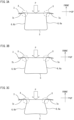
- FIGS. 2A and 2B show a cross-sectional view of a model of the bumper beam, which was used in the dynamic 3-point bending simulation analysis.
- FIG. 2A shows a case of the bumper beam of Case 1
- FIG. 2B shows a case of the bumper beam of Case 2.
- a load P in a direction toward the plate section 5 was applied over the entire area in the up-and-down direction to a center in the lengthwise direction of the second member 3 in Case 1.
- FIG. 2A a load P in a direction toward the plate section 5 was applied over the entire area in the up-and-down direction to a center in the lengthwise direction of the second member 3 in Case 1.
- FIGS. 3A to 3C show a diagram to show deformation behavior of the bumper beam of Case 1.
- the deformation of the bumper beam progresses in the order shown in FIGS. 3A, 3B and 3C .
- compressive force acts along the lengthwise direction of the bumper beam on the vicinity of end sections X of the wall sections 6a, 6b (hereinafter, also referred to generically as a wall section 6).
- the compressive force is force which tends to cause each of the two wall sections 6 to contact in the lengthwise direction of the bumper beam. Due to the action of such compressive force, the end section X on the second member 3 side of the wall section 6 moves toward the center in the vehicle up-and-down direction. As a result, the wall section 6 deforms, and eventually buckles.
- FIG. 4 is a load-deflection diagram relating to the bumper beams of Case 1 and Case 2.
- the ordinate indicates the load, and the abscissa indicates the deflection.
- the solid line indicates the result of the bumper beam of Case 1
- the broken line indicates the result of the bumper beam of Case 2.
- the load-deflection diagram shown in FIG. 4 reveals the followings.
- Case 1 the load becomes maximum when the deflection is about 38 mm.
- the maximum load is about 62 kN.
- the wall section 6 buckles.
- the deflection when the deflection is about 42 mm, the load becomes maximum.
- the maximum load is about 50 kN.
- the bumper beam 1 of the present embodiment is disposed with an inner plate 4 substantially in parallel with the second member 3 in a space formed by the first member 2 and the second member 3.
- the end sections 4a, 4b of the inner plate 4 are respectively joined to the upper and lower wall sections 6a, 6b.
- the position of the inner plate 4 is preferably closer to the second member 3.
- a ratio d1/h relating to the inner plate 4 is preferably not less than 0 and not more than 0.6.
- h indicates an interval between the second member 3 and the plate section 5 of the first member 2
- d1 indicates an interval between the second member 3 and the inner plate 4. This point will be described referring to FIG. 5 .
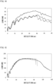
- FIG. 5 is a diagram to show the energy absorption efficiency of bumper beams having a different ratio d1/h, which relates to the position of the inner plate 4.
- the results shown in FIG. 5 were obtained by a similar dynamic 3-point bending simulation analysis as described above. Simulation analysis was conducted on each bumper beam in which the ratio d1/h, which relates to the position of the inner plate 4 of the bumper beam shown in FIG.1 , was widely varied. Other analysis conditions were the same as those for the simulation analysis shown in FIGS. 3A to 3C , and FIG. 4 described above. Referring to FIG. 5 , the energy absorption efficiency exhibited a maximum value at a ratio d1/h of about 0.16. As the ratio d1/h increased more than 0.16, the energy absorption efficiency deteriorated.
- the ratio d1/h relating to the position of the inner plate 4 is not more than 0.2, the inner plate 4 and the second member 3 are brought into contact with each other in an early stage during application of load. For that reason, the deflection of the second member 3 is limited, and thereby the movement of the end section X of the wall section 6 shown in FIG. 3A is limited. Therefore, the wall section 6 is less likely to buckle.
- the present inventors studied on the deformation behavior of a bumper beam whose ratio d1/h is 0.16 by means of the dynamic 3-point bending simulation analysis. The analysis conditions were the same as those of the simulation analysis shown in FIGS. 3A to 3C , and FIG. 4 as described above. The analysis results are shown in FIGS. 6A to 6D .
- the inner plate 4 when the ratio di/h is 0, the inner plate 4 is in contact with the second member 3 before the load P is applied. In this case, the modes of deformation of the second member 3 and the inner plate 4 are different. In other words, the second member 3 and the inner plate 4 deform in an integral manner. For that reason, the energy absorption efficiency deteriorates compared with when the ratio d1/h is 0.16. Therefore, a preferable lower limit of the ratio d1/h is 0.1. However, the energy absorption efficiency of a bumper beam when the ratio d1/h is 0 is higher than the energy absorption efficiency of a bumper beam without the inner plate 4. For that reason, the ratio d1/h may be 0.
- the bumper beam of the first embodiment exhibits high energy absorption efficiency since the inner plate suppresses the buckling of the wall section.
- the buckling of the wall section is suppressed too much extent, when a concentrated load is applied to a center in the lengthwise direction of the bumper beam, cracking may occur in the plate section of the first member on the rear side before the wall section buckles. Even if the wall section does not buckle, the energy absorption efficiency of the bumper beam will significantly deteriorate, if cracking occurs in the plate section.
- FIG. 8 is a plan view of a bumper beam in which a concentrated load is applied to a center in a lengthwise direction.
- the character "right” indicates the right side of the vehicle.
- the vicinity of the region to which the concentrated load P is applied deflects toward rearward of the vehicle (direction inward of the vehicle).
- the plate section 5 of the first member is disposed on the rear side of the bumper beam, it is subject to force in tensile direction (left-and-right direction of the vehicle). If this force in tensile direction is excessively large, cracking occurs in the plate section 5.
- the position of the inner plate is limited in the lengthwise direction of the bumper beam.
- the present inventors determined suitable position of the inner plate in the lengthwise direction of the bumper beam by means of Example 3 to be described below. This point will be described referring to FIG. 9 .
- the plate thickness t2 of the inner plate 4 is preferably not more than the plate thickness t1 of the first member 2. This is for the purpose of optimizing the timing of buckling occurrence in the wall section 6 and suppressing cracking from occurring in the plate section 5.
- the ratio t2/t1 between the plate thickness t1 of the first member 2 and the plate thickness t2 of the inner plate 4 is preferably not less than 0.7 and not more than 1.0.
- the ratio t2/t1 When the ratio t2/t1 is less than 0.7, the strength of the inner plate 4 is low, and therefore the wall section 6 will have buckled in an early stage. When the ratio t2/t1 is more than 1.0, the strength of the inner plate 4 is high, and therefore cracking is likely to occur in the plate section 5 when a concentrated load P is applied to the center in the lengthwise direction of the bumper beam.
- a preferable lower limit of the ratio t2/t1 is 0.8, and a preferable upper limit thereof is 0.9.
- the tensile strength TS2 of the inner plate 4 is preferably not more than the tensile strength TS1 of the first member 2.
- a ratio TS2/TS1 between the tensile strength TS1 of the first member 2 and the tensile strength TS2 of the inner plate 4 is preferably not less than 0.4 and not more than 1.0.
- the ratio TS2/TS1 is less than 0.4, the strength of the inner plate 4 is low, and therefore the wall section 6 will have buckled in an early stage.
- the bumper beam is made of a metal plate.
- the metal plate include a steel plate, aluminum plate, titanium plate, magnesium plate, copper plate, nickel plate, or an alloy plate thereof, and multi-layer metal plate.
- the first member and the second member are made of a steel plate having a tensile strength of not less than 1 GPa. In this case, it is possible to further increase the strength of the bumper beam, thereby improving the safety of the vehicle body.
- the bumper beam of the present embodiment is applied as a bumper beam of a front bumper of an automobile.
- the bumper beam of the present embodiment will not be limited to the bumper beam of a front bumper.
- the bumper beam of the present embodiment may be disposed in the rear of the vehicle. In other words, the bumper beam of the present embodiment can be applied to rear bumpers, and the like. In either case, the second member of the bumper beam is disposed facing the outside of the vehicle.
- Example 1 load application simulation analysis was conducted on the bumper beams in which inner plates 4 were disposed differently to investigate energy absorption efficiency.
- FIGS. 11A to 11C are cross sectional views of analysis models of the bumper beams used in Example 1.
- FIG. 11A shows a model of Inventive Examples 1 and 2 of the present invention
- FIG. 11B shows a model of Comparative Example 1
- FIG. 11C shows a model of Comparative Example 2.
- the ratio d1/h relating to position of the inner plate 4 of Inventive Example 1 of the present invention was set at 0.16
- the ratio d1/h relating to the position of the inner plate 4 of Inventive Example 2 of the present invention was set at 0.5.
- Comparative Example 1 a bumper beam having no inner plate 4 was supposed.
- Comparative Example 2 a bumper beam in which the inner plate 4 was disposed perpendicular to the second member 3 was supposed.
- a width W1 of the wall section 6 of the first member 2 was supposed to be 60 mm
- a width W2 of the plate section 5 was supposed to be 80 mm
- a width W3 of the second member 3 was supposed to be 120 mm.
- the load P was applied to a center of the second member 3 toward the first member 2.
- the first member 2, the second member 3, and the inner plate 4 were supposed to be a steel plate having a tensile strength of 1800 MPa, and a plate thickness of 1.4 mm.
- FIG. 12 is a load-deflection curve relating to each bumper beam of Example 1.
- a solid line indicates the result of Inventive Example 1 of the present invention
- broken line indicates that of Inventive Example 2 of the present invention
- one-dot chain line indicates that of Comparative Example 1
- a two-dot chain line indicates that of Comparative Example 2.
- the wall section 6 did not buckle until the deflection reached about 38 mm. In Comparative Examples 1 and 2, the wall section 6 buckled before the deflection reached 30 mm.
- the maximum permissible load was about 73 kN in Inventive Example 1 of the present invention, and was about 62 kN in Inventive Example 2 of the present invention.
- the maximum permissible load was about 45 kN in Comparative Example 1, and was about 58 kN in Comparative Example 2.
- Example 1 Based on the analysis results of Example 1, the energy absorption efficiency of each bumper beam whose deflection was up to 60 mm was calculated. The results are shown in Table 1. [Table 1] E 1 Mass (kg) Absorbed energy (kJ) Energy absorption efficiency (kJ/kg) Inventive Example 1 of the present invention 5.0 3.4 0.68 Inventive Example 2 of the present invention 5.0 2.8 0.56 Comparative Example 1 3.8 1.7 0.44 Comparative Example 2 4.8 2.5 0.51
- the energy absorption efficiency of Inventive Example 1 of the present invention was 0.68 kJ/kg, and that of Inventive Example 2 of the present invention was 0.56 kJ/kg.
- the energy absorption efficiency of Comparative Example 1 was 0.44 kJ/kg, and that of Comparative Example 2 was 0.51 kJ/kg.
- Example 2 the maximum permissible load was compared between the bumper beam of Case 1 in which the inner plate 4 was added, and the bumper beam of Case 2 in which the inner plate 4 was added.
- Example 2 the result of Inventive Example 2 of the present invention in Example 1 was cited, and as Comparative Example 3 and Comparative Example 4, the inner plate 4 was disposed in the bumper beam of Case 2, and a similar load application simulation analysis as in Example 1 was conducted.
- FIG. 13 is a cross-sectional view of a bumper beam of Case 2 in which the inner plate 4 used in Case 2 was added.
- a ratio d2/h relating to the position of the inner plate 4 of Comparative Example 3 was supposed to be 0.33, and a ratio d2/h relating to the position of the inner plate 4 of Comparative Example 4 was supposed to be 0.5.
- the load P was applied to the center of the plate section 5.
- d2 indicates an interval between the plate section 5 and the inner plate 4. In other words, the interval d2 corresponds to a depth from the plate section 5 to the inner plate 4.
- FIG. 14 is a load-deflection curve relating to each bumper beam of Example 2.
- Inventive Example 2 of the present invention conducted in Example 1 is shown together in FIG. 14 .
- a solid line indicates Inventive Example 2 of the present invention
- a one-dot chain line indicates Comparative Example 3
- a two-dot chain line indicates Comparative Example 4.
- both Comparative Examples 3 and 4 exhibited that the wall section 6 buckled when the deflection was more than 40 mm.
- the maximum permissible loads of Comparative Examples 3 and 4 were both about 48 kN.
- Example 3 a load application simulation analysis was conducted on bumper beams in which a region in which the inner plate 4 was disposed in the lengthwise direction was limited, to investigate occurrence or nonoccurrence of cracking in the plate section.
- a width W1 of the wall section 6 of the first member 2 was supposed to be 90 mm
- a width W2 of the plate section 5 was supposed to be 80 mm
- a width W3 of the second member 3 was supposed to be 120 mm.
- a distance L1 of the bumper beam 10 of the second embodiment shown in FIG.9 was widely varied to perform simulation analysis similar to that in Example 1.
Landscapes
- Engineering & Computer Science (AREA)
- Mechanical Engineering (AREA)
- Body Structure For Vehicles (AREA)
- Vibration Dampers (AREA)
Claims (11)
- Poutre de pare-chocs (1) pour un véhicule, comprenant :un premier élément (2) incluant une section de plaque (5), deux sections de paroi (6a, 6b) raccordées à deux sections latérales de la section de plaque (5), respectivement, et deux sections de bride (7a, 7b) se raccordant aux deux sections de paroi (6a, 6b), respectivement ;un deuxième élément (3) en forme de plaque qui est relié aux deux sections de bride (7a, 7b) du premier élément (2) et qui ferme un interstice entre les deux sections de bride (7a, 7b) au moins ; etune plaque intérieure (4) qui est disposée sensiblement en parallèle avec le deuxième élément (3) dans un espace formé par le premier élément (2) et le deuxième élément (3), dans laquellele deuxième élément (3) parmi le premier élément (2) et le deuxième élément (3) est disposé face à l'extérieur du véhicule ;caractérisée en ce que la plaque intérieure (4) n'est reliée qu'aux deux sections de paroi (6a, 6b) du premier élément (2), que la plaque intérieure (4) a des sections d'extrémité (4a, 4b) qui sont pliées, et que les sections d'extrémité (4a, 4b) sont respectivement reliées aux deux sections de paroi (6a, 6b) du premier élément (2).
- Poutre de pare-chocs (1) pour un véhicule selon la revendication 1, dans laquelle
un rapport d1/h est non inférieur à 0 et non supérieur à 0,6, où h est un intervalle entre le deuxième élément (3) et la section de plaque (5) du premier élément (2), et d1 est un intervalle entre le deuxième élément (3) et la plaque intérieure (4). - Poutre de pare-chocs (1) pour un véhicule selon la revendication 1, dans laquelle
un rapport d1/h est non inférieur à 0 et non supérieur à 0,2, où h est un intervalle entre le deuxième élément (3) et la section de plaque (5) du premier élément (2), et d1 est un intervalle entre le deuxième élément (3) et la plaque intérieure (4). - Poutre de pare-chocs (1) pour un véhicule selon la revendication 2 ou 3, dans laquelle
la plaque intérieure (4) est disposée au moins partiellement dans une région à une distance non inférieure à -0,2×L et non supérieure à 0,2×L d'un centre dans un sens de la longueur de la poutre de pare-chocs (1), où L est une longueur totale de la poutre de pare-chocs (1). - Poutre de pare-chocs (1) pour un véhicule selon la revendication 2 ou 3, dans laquelle
la plaque intérieure (4) est disposée au moins partiellement dans une région à une distance non inférieure à -0,1xL et non supérieure à 0,1xL d'un centre dans un sens de la longueur de la poutre de pare-chocs (1), où L est une longueur totale de la poutre de pare-chocs (1). - Poutre de pare-chocs (1) pour un véhicule selon l'une quelconque des revendications 1 à 5, dans laquelle le premier élément (2) et la plaque intérieure (4) sont constitués d'une plaque en métal, et un rapport t2/t1 est non inférieur à 0,7 et non supérieur à 1,0, où t1 est une épaisseur de plaque du premier élément (2), et t2 est une épaisseur de plaque de la plaque intérieure (4).
- Poutre de pare-chocs (1) pour un véhicule selon l'une quelconque des revendications 1 à 6, dans laquelle un rapport TS2/TS1 est non inférieur à 0,4 et non supérieur à 1,0, où TS1 est une résistance à la traction du premier élément (2), et TS2 est une résistance à la traction de la plaque intérieure (4).
- Poutre de pare-chocs (1) pour un véhicule selon l'une quelconque des revendications 1 à 7, dans laquelle la plaque intérieure (4) et les sections de paroi (6a, 6b) sont reliées par soudage.
- Poutre de pare-chocs (1) pour un véhicule selon l'une quelconque des revendications 1 à 8, dans laquelle le premier élément (2) et le deuxième élément (3) sont constitués d'une tôle d'acier, et une résistance à la traction de la tôle d'acier est non inférieure à 1 GPa.
- Poutre de pare-chocs selon l'une quelconque des revendications 1 à 8, dans laquelle les sections d'extrémité (4a, 4b) de la plaque intérieure (4) sont pliées vers le premier élément (2).
- Véhicule comprenant la poutre de pare-chocs (1) pour un véhicule selon l'une quelconque des revendications 1 à 10 à l'avant ou à l'arrière du véhicule, dans lequel le deuxième élément (3) de la poutre de pare-chocs (1) est disposé face à l'extérieur du véhicule.
Applications Claiming Priority (2)
| Application Number | Priority Date | Filing Date | Title |
|---|---|---|---|
| JP2015009105 | 2015-01-21 | ||
| PCT/JP2016/000257 WO2016117335A1 (fr) | 2015-01-21 | 2016-01-19 | Poutre de pare-chocs |
Publications (3)
| Publication Number | Publication Date |
|---|---|
| EP3248845A1 EP3248845A1 (fr) | 2017-11-29 |
| EP3248845A4 EP3248845A4 (fr) | 2018-06-13 |
| EP3248845B1 true EP3248845B1 (fr) | 2025-04-16 |
Family
ID=56416887
Family Applications (1)
| Application Number | Title | Priority Date | Filing Date |
|---|---|---|---|
| EP16739944.3A Active EP3248845B1 (fr) | 2015-01-21 | 2016-01-19 | Poutre de pare-chocs |
Country Status (11)
| Country | Link |
|---|---|
| US (1) | US10259410B2 (fr) |
| EP (1) | EP3248845B1 (fr) |
| JP (1) | JP6402781B2 (fr) |
| KR (1) | KR101965091B1 (fr) |
| CN (1) | CN107206951B (fr) |
| BR (1) | BR112017014184A2 (fr) |
| CA (1) | CA2974327C (fr) |
| MX (1) | MX379185B (fr) |
| RU (1) | RU2674366C1 (fr) |
| TW (1) | TWI609803B (fr) |
| WO (1) | WO2016117335A1 (fr) |
Families Citing this family (11)
| Publication number | Priority date | Publication date | Assignee | Title |
|---|---|---|---|---|
| ES2809128T3 (es) * | 2015-07-08 | 2021-03-03 | Nippon Steel Corp | Refuerzo de parachoques y vehículo provisto con el mismo |
| KR102127301B1 (ko) | 2017-03-23 | 2020-06-26 | 닛폰세이테츠 가부시키가이샤 | 범퍼 빔 |
| WO2019035185A1 (fr) * | 2017-08-15 | 2019-02-21 | 新日鐵住金株式会社 | Poutre de pare-chocs et véhicule |
| DE102017123325B4 (de) * | 2017-10-09 | 2024-09-12 | Kirchhoff Automotive Deutschland Gmbh | Stoßfängerquerträger |
| KR20200018275A (ko) * | 2018-08-10 | 2020-02-19 | 롬엔드하스전자재료코리아유한회사 | 유기 전계 발광 화합물 및 이를 포함하는 유기 전계 발광 소자 |
| WO2020053626A1 (fr) * | 2018-09-12 | 2020-03-19 | Arcelormittal | Poutre de pare-chocs ayant un renfort en acier |
| KR102342441B1 (ko) * | 2019-08-05 | 2021-12-22 | 부산대학교 산학협력단 | 전기 변색 소재, 이의 제조방법 및 이를 포함하는 전기 변색 소자 제조 방법 |
| CN113268814B (zh) * | 2021-06-18 | 2022-05-17 | 中国第一汽车股份有限公司 | 一种保险杠总成表面刚度的设计方法 |
| KR20240120255A (ko) | 2023-01-31 | 2024-08-07 | 동원금속 (주) | 자동차 범퍼 백빔용의 빔프레임 |
| WO2024210056A1 (fr) * | 2023-04-03 | 2024-10-10 | 日本製鉄株式会社 | Poutre de pare-chocs |
| JPWO2024210053A1 (fr) * | 2023-04-03 | 2024-10-10 |
Family Cites Families (17)
| Publication number | Priority date | Publication date | Assignee | Title |
|---|---|---|---|---|
| JPH06171441A (ja) | 1992-10-09 | 1994-06-21 | Nkk Corp | バンパービームおよびバンパー |
| JPH06328988A (ja) * | 1993-03-23 | 1994-11-29 | Toupure Kk | 車両用バンパービーム |
| JPH07309184A (ja) | 1994-05-20 | 1995-11-28 | Kobe Steel Ltd | 自動車用補強部材 |
| JP3120957B2 (ja) * | 1995-07-07 | 2000-12-25 | 本田技研工業株式会社 | 車両用バンパビームの製造方法 |
| TW459679U (en) * | 1998-07-21 | 2001-10-11 | Chen Chuen Mau | Bumper for vehicles |
| TW429908U (en) * | 1999-02-26 | 2001-04-11 | Li Ching Huang | Cushion device for automobile bumper |
| GB0114684D0 (en) * | 2001-06-15 | 2001-08-08 | Dow Chemical Co | Automobile assembly |
| US7407219B2 (en) * | 2004-03-24 | 2008-08-05 | Shape Corporation | Energy management beam |
| JP4057815B2 (ja) * | 2002-01-31 | 2008-03-05 | 株式会社アステア | バンパ補強材 |
| DE102006000481A1 (de) * | 2005-09-27 | 2007-04-05 | Tokai Rubber Industries, Ltd., Komaki | Stossabsorbierendes Element für Fahrzeuge |
| JP4735843B2 (ja) * | 2006-06-29 | 2011-07-27 | マツダ株式会社 | 自動車のバンパ構造 |
| JP4759497B2 (ja) * | 2006-11-29 | 2011-08-31 | 東海ゴム工業株式会社 | 自動車用衝撃吸収部材 |
| JP5056643B2 (ja) * | 2008-07-18 | 2012-10-24 | 住友金属工業株式会社 | バンパーリインフォースメントおよびその製造方法 |
| JP5329188B2 (ja) * | 2008-11-21 | 2013-10-30 | 株式会社アステア | バンパ補強材 |
| DE102010050960A1 (de) * | 2010-11-10 | 2012-05-10 | Gm Global Technology Operations Llc (N.D.Ges.D. Staates Delaware) | Stoßfängerquerträger für ein Kraftfahrzeug, Verstärkungsbauteil für einen Stoßfängerquerträger und Verfahren zur Herstellung eines Stoßfängerquerträgers |
| TWI451898B (zh) * | 2012-01-06 | 2014-09-11 | Yung Yu Chen | 齒輪傳動機構及使用該機構之遊戲機 |
| SE537087C2 (sv) * | 2013-03-13 | 2014-12-30 | Gestamp Hardtech Ab | Stötfångarbalk |
-
2016
- 2016-01-19 BR BR112017014184A patent/BR112017014184A2/pt not_active Application Discontinuation
- 2016-01-19 MX MX2017009446A patent/MX379185B/es unknown
- 2016-01-19 EP EP16739944.3A patent/EP3248845B1/fr active Active
- 2016-01-19 WO PCT/JP2016/000257 patent/WO2016117335A1/fr not_active Ceased
- 2016-01-19 KR KR1020177022798A patent/KR101965091B1/ko active Active
- 2016-01-19 JP JP2016570551A patent/JP6402781B2/ja active Active
- 2016-01-19 CA CA2974327A patent/CA2974327C/fr not_active Expired - Fee Related
- 2016-01-19 CN CN201680006411.9A patent/CN107206951B/zh active Active
- 2016-01-19 US US15/543,313 patent/US10259410B2/en active Active
- 2016-01-19 RU RU2017129254A patent/RU2674366C1/ru not_active IP Right Cessation
- 2016-01-20 TW TW105101740A patent/TWI609803B/zh not_active IP Right Cessation
Also Published As
| Publication number | Publication date |
|---|---|
| CN107206951A (zh) | 2017-09-26 |
| WO2016117335A1 (fr) | 2016-07-28 |
| EP3248845A4 (fr) | 2018-06-13 |
| CN107206951B (zh) | 2020-08-21 |
| JPWO2016117335A1 (ja) | 2017-09-28 |
| MX2017009446A (es) | 2017-11-08 |
| JP6402781B2 (ja) | 2018-10-10 |
| US10259410B2 (en) | 2019-04-16 |
| CA2974327C (fr) | 2019-06-18 |
| BR112017014184A2 (pt) | 2018-01-09 |
| KR101965091B1 (ko) | 2019-04-02 |
| TWI609803B (zh) | 2018-01-01 |
| EP3248845A1 (fr) | 2017-11-29 |
| RU2674366C1 (ru) | 2018-12-07 |
| KR20170105081A (ko) | 2017-09-18 |
| TW201641326A (zh) | 2016-12-01 |
| US20180001853A1 (en) | 2018-01-04 |
| MX379185B (es) | 2025-03-11 |
| CA2974327A1 (fr) | 2016-07-28 |
Similar Documents
| Publication | Publication Date | Title |
|---|---|---|
| US10259410B2 (en) | Bumper beam | |
| US8801083B2 (en) | Front vehicle body structure | |
| EP3670272B1 (fr) | Poutre de pare-chocs et véhicule | |
| JP2018202897A (ja) | バンパビーム構造 | |
| CN108430857B (zh) | 车辆后部构造 | |
| RU2757795C1 (ru) | Брус буфера, имеющий стальное усиление | |
| JP2017159895A (ja) | 車両用構造部材 | |
| US12065093B2 (en) | Bumper arrangement with end-side hollow profile | |
| JP4932688B2 (ja) | 自動車車体用ルーフ補強材 | |
| US11981370B2 (en) | Structural member for vehicle | |
| JP2014101094A (ja) | 車体構造 | |
| JP7264597B2 (ja) | 車両用構造部材及び車両 | |
| WO2010113894A1 (fr) | Poutre de pare-chocs de véhicule | |
| JP2018149975A (ja) | バンパリインフォースメント | |
| JP5158246B2 (ja) | 衝撃吸収部材 | |
| JP4706656B2 (ja) | バンパステイ | |
| JP2021024465A (ja) | 車体構造 | |
| JP2019093876A (ja) | バンパービーム及び車両 |
Legal Events
| Date | Code | Title | Description |
|---|---|---|---|
| STAA | Information on the status of an ep patent application or granted ep patent |
Free format text: STATUS: THE INTERNATIONAL PUBLICATION HAS BEEN MADE |
|
| PUAI | Public reference made under article 153(3) epc to a published international application that has entered the european phase |
Free format text: ORIGINAL CODE: 0009012 |
|
| STAA | Information on the status of an ep patent application or granted ep patent |
Free format text: STATUS: REQUEST FOR EXAMINATION WAS MADE |
|
| 17P | Request for examination filed |
Effective date: 20170619 |
|
| AK | Designated contracting states |
Kind code of ref document: A1 Designated state(s): AL AT BE BG CH CY CZ DE DK EE ES FI FR GB GR HR HU IE IS IT LI LT LU LV MC MK MT NL NO PL PT RO RS SE SI SK SM TR |
|
| AX | Request for extension of the european patent |
Extension state: BA ME |
|
| DAV | Request for validation of the european patent (deleted) | ||
| DAX | Request for extension of the european patent (deleted) | ||
| A4 | Supplementary search report drawn up and despatched |
Effective date: 20180515 |
|
| RIC1 | Information provided on ipc code assigned before grant |
Ipc: B60R 19/04 20060101AFI20180508BHEP |
|
| RAP1 | Party data changed (applicant data changed or rights of an application transferred) |
Owner name: NIPPON STEEL CORPORATION |
|
| STAA | Information on the status of an ep patent application or granted ep patent |
Free format text: STATUS: EXAMINATION IS IN PROGRESS |
|
| 17Q | First examination report despatched |
Effective date: 20220311 |
|
| GRAP | Despatch of communication of intention to grant a patent |
Free format text: ORIGINAL CODE: EPIDOSNIGR1 |
|
| STAA | Information on the status of an ep patent application or granted ep patent |
Free format text: STATUS: GRANT OF PATENT IS INTENDED |
|
| INTG | Intention to grant announced |
Effective date: 20241108 |
|
| GRAJ | Information related to disapproval of communication of intention to grant by the applicant or resumption of examination proceedings by the epo deleted |
Free format text: ORIGINAL CODE: EPIDOSDIGR1 |
|
| STAA | Information on the status of an ep patent application or granted ep patent |
Free format text: STATUS: EXAMINATION IS IN PROGRESS |
|
| GRAP | Despatch of communication of intention to grant a patent |
Free format text: ORIGINAL CODE: EPIDOSNIGR1 |
|
| STAA | Information on the status of an ep patent application or granted ep patent |
Free format text: STATUS: GRANT OF PATENT IS INTENDED |
|
| INTC | Intention to grant announced (deleted) | ||
| INTG | Intention to grant announced |
Effective date: 20250117 |
|
| GRAS | Grant fee paid |
Free format text: ORIGINAL CODE: EPIDOSNIGR3 |
|
| GRAA | (expected) grant |
Free format text: ORIGINAL CODE: 0009210 |
|
| STAA | Information on the status of an ep patent application or granted ep patent |
Free format text: STATUS: THE PATENT HAS BEEN GRANTED |
|
| AK | Designated contracting states |
Kind code of ref document: B1 Designated state(s): AL AT BE BG CH CY CZ DE DK EE ES FI FR GB GR HR HU IE IS IT LI LT LU LV MC MK MT NL NO PL PT RO RS SE SI SK SM TR |
|
| REG | Reference to a national code |
Ref country code: GB Ref legal event code: FG4D |
|
| REG | Reference to a national code |
Ref country code: CH Ref legal event code: EP Ref country code: DE Ref legal event code: R096 Ref document number: 602016091912 Country of ref document: DE |
|
| REG | Reference to a national code |
Ref country code: IE Ref legal event code: FG4D |
|
| REG | Reference to a national code |
Ref country code: NL Ref legal event code: MP Effective date: 20250416 |
|
| PG25 | Lapsed in a contracting state [announced via postgrant information from national office to epo] |
Ref country code: NL Free format text: LAPSE BECAUSE OF FAILURE TO SUBMIT A TRANSLATION OF THE DESCRIPTION OR TO PAY THE FEE WITHIN THE PRESCRIBED TIME-LIMIT Effective date: 20250416 |
|
| REG | Reference to a national code |
Ref country code: AT Ref legal event code: MK05 Ref document number: 1785400 Country of ref document: AT Kind code of ref document: T Effective date: 20250416 |
|
| PG25 | Lapsed in a contracting state [announced via postgrant information from national office to epo] |
Ref country code: PT Free format text: LAPSE BECAUSE OF FAILURE TO SUBMIT A TRANSLATION OF THE DESCRIPTION OR TO PAY THE FEE WITHIN THE PRESCRIBED TIME-LIMIT Effective date: 20250818 Ref country code: FI Free format text: LAPSE BECAUSE OF FAILURE TO SUBMIT A TRANSLATION OF THE DESCRIPTION OR TO PAY THE FEE WITHIN THE PRESCRIBED TIME-LIMIT Effective date: 20250416 Ref country code: ES Free format text: LAPSE BECAUSE OF FAILURE TO SUBMIT A TRANSLATION OF THE DESCRIPTION OR TO PAY THE FEE WITHIN THE PRESCRIBED TIME-LIMIT Effective date: 20250416 |
|
| REG | Reference to a national code |
Ref country code: LT Ref legal event code: MG9D |
|
| PG25 | Lapsed in a contracting state [announced via postgrant information from national office to epo] |
Ref country code: NO Free format text: LAPSE BECAUSE OF FAILURE TO SUBMIT A TRANSLATION OF THE DESCRIPTION OR TO PAY THE FEE WITHIN THE PRESCRIBED TIME-LIMIT Effective date: 20250716 Ref country code: GR Free format text: LAPSE BECAUSE OF FAILURE TO SUBMIT A TRANSLATION OF THE DESCRIPTION OR TO PAY THE FEE WITHIN THE PRESCRIBED TIME-LIMIT Effective date: 20250717 |
|
| PG25 | Lapsed in a contracting state [announced via postgrant information from national office to epo] |
Ref country code: PL Free format text: LAPSE BECAUSE OF FAILURE TO SUBMIT A TRANSLATION OF THE DESCRIPTION OR TO PAY THE FEE WITHIN THE PRESCRIBED TIME-LIMIT Effective date: 20250416 |
|
| PG25 | Lapsed in a contracting state [announced via postgrant information from national office to epo] |
Ref country code: BG Free format text: LAPSE BECAUSE OF FAILURE TO SUBMIT A TRANSLATION OF THE DESCRIPTION OR TO PAY THE FEE WITHIN THE PRESCRIBED TIME-LIMIT Effective date: 20250416 |
|
| PG25 | Lapsed in a contracting state [announced via postgrant information from national office to epo] |
Ref country code: HR Free format text: LAPSE BECAUSE OF FAILURE TO SUBMIT A TRANSLATION OF THE DESCRIPTION OR TO PAY THE FEE WITHIN THE PRESCRIBED TIME-LIMIT Effective date: 20250416 |
|
| PG25 | Lapsed in a contracting state [announced via postgrant information from national office to epo] |
Ref country code: AT Free format text: LAPSE BECAUSE OF FAILURE TO SUBMIT A TRANSLATION OF THE DESCRIPTION OR TO PAY THE FEE WITHIN THE PRESCRIBED TIME-LIMIT Effective date: 20250416 |
|
| PG25 | Lapsed in a contracting state [announced via postgrant information from national office to epo] |
Ref country code: RS Free format text: LAPSE BECAUSE OF FAILURE TO SUBMIT A TRANSLATION OF THE DESCRIPTION OR TO PAY THE FEE WITHIN THE PRESCRIBED TIME-LIMIT Effective date: 20250716 |
|
| PG25 | Lapsed in a contracting state [announced via postgrant information from national office to epo] |
Ref country code: IS Free format text: LAPSE BECAUSE OF FAILURE TO SUBMIT A TRANSLATION OF THE DESCRIPTION OR TO PAY THE FEE WITHIN THE PRESCRIBED TIME-LIMIT Effective date: 20250816 |
|
| PG25 | Lapsed in a contracting state [announced via postgrant information from national office to epo] |
Ref country code: LV Free format text: LAPSE BECAUSE OF FAILURE TO SUBMIT A TRANSLATION OF THE DESCRIPTION OR TO PAY THE FEE WITHIN THE PRESCRIBED TIME-LIMIT Effective date: 20250416 |
|
| PG25 | Lapsed in a contracting state [announced via postgrant information from national office to epo] |
Ref country code: DK Free format text: LAPSE BECAUSE OF FAILURE TO SUBMIT A TRANSLATION OF THE DESCRIPTION OR TO PAY THE FEE WITHIN THE PRESCRIBED TIME-LIMIT Effective date: 20250416 Ref country code: SM Free format text: LAPSE BECAUSE OF FAILURE TO SUBMIT A TRANSLATION OF THE DESCRIPTION OR TO PAY THE FEE WITHIN THE PRESCRIBED TIME-LIMIT Effective date: 20250416 |
|
| REG | Reference to a national code |
Ref country code: DE Ref legal event code: R097 Ref document number: 602016091912 Country of ref document: DE |
|
| PG25 | Lapsed in a contracting state [announced via postgrant information from national office to epo] |
Ref country code: CZ Free format text: LAPSE BECAUSE OF FAILURE TO SUBMIT A TRANSLATION OF THE DESCRIPTION OR TO PAY THE FEE WITHIN THE PRESCRIBED TIME-LIMIT Effective date: 20250416 |
|
| PG25 | Lapsed in a contracting state [announced via postgrant information from national office to epo] |
Ref country code: EE Free format text: LAPSE BECAUSE OF FAILURE TO SUBMIT A TRANSLATION OF THE DESCRIPTION OR TO PAY THE FEE WITHIN THE PRESCRIBED TIME-LIMIT Effective date: 20250416 |
|
| PG25 | Lapsed in a contracting state [announced via postgrant information from national office to epo] |
Ref country code: SK Free format text: LAPSE BECAUSE OF FAILURE TO SUBMIT A TRANSLATION OF THE DESCRIPTION OR TO PAY THE FEE WITHIN THE PRESCRIBED TIME-LIMIT Effective date: 20250416 Ref country code: RO Free format text: LAPSE BECAUSE OF FAILURE TO SUBMIT A TRANSLATION OF THE DESCRIPTION OR TO PAY THE FEE WITHIN THE PRESCRIBED TIME-LIMIT Effective date: 20250416 |
|
| PG25 | Lapsed in a contracting state [announced via postgrant information from national office to epo] |
Ref country code: IT Free format text: LAPSE BECAUSE OF FAILURE TO SUBMIT A TRANSLATION OF THE DESCRIPTION OR TO PAY THE FEE WITHIN THE PRESCRIBED TIME-LIMIT Effective date: 20250416 |
|
| PLBE | No opposition filed within time limit |
Free format text: ORIGINAL CODE: 0009261 |
|
| STAA | Information on the status of an ep patent application or granted ep patent |
Free format text: STATUS: NO OPPOSITION FILED WITHIN TIME LIMIT |
|
| REG | Reference to a national code |
Ref country code: CH Ref legal event code: L10 Free format text: ST27 STATUS EVENT CODE: U-0-0-L10-L00 (AS PROVIDED BY THE NATIONAL OFFICE) Effective date: 20260225 |
|
| 26N | No opposition filed |
Effective date: 20260119 |
|
| PGFP | Annual fee paid to national office [announced via postgrant information from national office to epo] |
Ref country code: DE Payment date: 20260121 Year of fee payment: 11 |
|
| PGFP | Annual fee paid to national office [announced via postgrant information from national office to epo] |
Ref country code: FR Payment date: 20260123 Year of fee payment: 11 |