EP3248852B1 - Procédé de fonctionnement d'un dispositif de traitement pour des données de capteur d'un capteur disposé dans un véhicule automobile et véhicule automobile - Google Patents
Procédé de fonctionnement d'un dispositif de traitement pour des données de capteur d'un capteur disposé dans un véhicule automobile et véhicule automobile Download PDFInfo
- Publication number
- EP3248852B1 EP3248852B1 EP17172191.3A EP17172191A EP3248852B1 EP 3248852 B1 EP3248852 B1 EP 3248852B1 EP 17172191 A EP17172191 A EP 17172191A EP 3248852 B1 EP3248852 B1 EP 3248852B1
- Authority
- EP
- European Patent Office
- Prior art keywords
- vehicle
- information
- movement
- sensor
- processing device
- Prior art date
- Legal status (The legal status is an assumption and is not a legal conclusion. Google has not performed a legal analysis and makes no representation as to the accuracy of the status listed.)
- Active
Links
Images


Classifications
-
- B—PERFORMING OPERATIONS; TRANSPORTING
- B60—VEHICLES IN GENERAL
- B60W—CONJOINT CONTROL OF VEHICLE SUB-UNITS OF DIFFERENT TYPE OR DIFFERENT FUNCTION; CONTROL SYSTEMS SPECIALLY ADAPTED FOR HYBRID VEHICLES; ROAD VEHICLE DRIVE CONTROL SYSTEMS FOR PURPOSES NOT RELATED TO THE CONTROL OF A PARTICULAR SUB-UNIT
- B60W40/00—Estimation or calculation of non-directly measurable driving parameters for road vehicle drive control systems not related to the control of a particular sub unit, e.g. by using mathematical models
- B60W40/02—Estimation or calculation of non-directly measurable driving parameters for road vehicle drive control systems not related to the control of a particular sub unit, e.g. by using mathematical models related to ambient conditions
- B60W40/04—Traffic conditions
-
- G—PHYSICS
- G01—MEASURING; TESTING
- G01S—RADIO DIRECTION-FINDING; RADIO NAVIGATION; DETERMINING DISTANCE OR VELOCITY BY USE OF RADIO WAVES; LOCATING OR PRESENCE-DETECTING BY USE OF THE REFLECTION OR RERADIATION OF RADIO WAVES; ANALOGOUS ARRANGEMENTS USING OTHER WAVES
- G01S13/00—Systems using the reflection or reradiation of radio waves, e.g. radar systems; Analogous systems using reflection or reradiation of waves whose nature or wavelength is irrelevant or unspecified
- G01S13/66—Radar-tracking systems; Analogous systems
- G01S13/72—Radar-tracking systems; Analogous systems for two-dimensional [2D] tracking, e.g. combination of angle and range tracking, track-while-scan radar
- G01S13/723—Radar-tracking systems; Analogous systems for two-dimensional [2D] tracking, e.g. combination of angle and range tracking, track-while-scan radar by using numerical data
-
- G—PHYSICS
- G01—MEASURING; TESTING
- G01S—RADIO DIRECTION-FINDING; RADIO NAVIGATION; DETERMINING DISTANCE OR VELOCITY BY USE OF RADIO WAVES; LOCATING OR PRESENCE-DETECTING BY USE OF THE REFLECTION OR RERADIATION OF RADIO WAVES; ANALOGOUS ARRANGEMENTS USING OTHER WAVES
- G01S13/00—Systems using the reflection or reradiation of radio waves, e.g. radar systems; Analogous systems using reflection or reradiation of waves whose nature or wavelength is irrelevant or unspecified
- G01S13/88—Radar or analogous systems specially adapted for specific applications
- G01S13/93—Radar or analogous systems specially adapted for specific applications for anti-collision purposes
- G01S13/931—Radar or analogous systems specially adapted for specific applications for anti-collision purposes of land vehicles
-
- G—PHYSICS
- G01—MEASURING; TESTING
- G01S—RADIO DIRECTION-FINDING; RADIO NAVIGATION; DETERMINING DISTANCE OR VELOCITY BY USE OF RADIO WAVES; LOCATING OR PRESENCE-DETECTING BY USE OF THE REFLECTION OR RERADIATION OF RADIO WAVES; ANALOGOUS ARRANGEMENTS USING OTHER WAVES
- G01S17/00—Systems using the reflection or reradiation of electromagnetic waves other than radio waves, e.g. lidar systems
- G01S17/02—Systems using the reflection of electromagnetic waves other than radio waves
- G01S17/06—Systems determining position data of a target
- G01S17/42—Simultaneous measurement of distance and other co-ordinates
-
- G—PHYSICS
- G01—MEASURING; TESTING
- G01S—RADIO DIRECTION-FINDING; RADIO NAVIGATION; DETERMINING DISTANCE OR VELOCITY BY USE OF RADIO WAVES; LOCATING OR PRESENCE-DETECTING BY USE OF THE REFLECTION OR RERADIATION OF RADIO WAVES; ANALOGOUS ARRANGEMENTS USING OTHER WAVES
- G01S17/00—Systems using the reflection or reradiation of electromagnetic waves other than radio waves, e.g. lidar systems
- G01S17/02—Systems using the reflection of electromagnetic waves other than radio waves
- G01S17/50—Systems of measurement based on relative movement of target
- G01S17/58—Velocity or trajectory determination systems; Sense-of-movement determination systems
-
- G—PHYSICS
- G01—MEASURING; TESTING
- G01S—RADIO DIRECTION-FINDING; RADIO NAVIGATION; DETERMINING DISTANCE OR VELOCITY BY USE OF RADIO WAVES; LOCATING OR PRESENCE-DETECTING BY USE OF THE REFLECTION OR RERADIATION OF RADIO WAVES; ANALOGOUS ARRANGEMENTS USING OTHER WAVES
- G01S17/00—Systems using the reflection or reradiation of electromagnetic waves other than radio waves, e.g. lidar systems
- G01S17/88—Lidar systems specially adapted for specific applications
- G01S17/93—Lidar systems specially adapted for specific applications for anti-collision purposes
- G01S17/931—Lidar systems specially adapted for specific applications for anti-collision purposes of land vehicles
-
- G—PHYSICS
- G01—MEASURING; TESTING
- G01S—RADIO DIRECTION-FINDING; RADIO NAVIGATION; DETERMINING DISTANCE OR VELOCITY BY USE OF RADIO WAVES; LOCATING OR PRESENCE-DETECTING BY USE OF THE REFLECTION OR RERADIATION OF RADIO WAVES; ANALOGOUS ARRANGEMENTS USING OTHER WAVES
- G01S7/00—Details of systems according to groups G01S13/00, G01S15/00, G01S17/00
- G01S7/48—Details of systems according to groups G01S13/00, G01S15/00, G01S17/00 of systems according to group G01S17/00
- G01S7/4802—Details of systems according to groups G01S13/00, G01S15/00, G01S17/00 of systems according to group G01S17/00 using analysis of echo signal for target characterisation; Target signature; Target cross-section
-
- G—PHYSICS
- G01—MEASURING; TESTING
- G01S—RADIO DIRECTION-FINDING; RADIO NAVIGATION; DETERMINING DISTANCE OR VELOCITY BY USE OF RADIO WAVES; LOCATING OR PRESENCE-DETECTING BY USE OF THE REFLECTION OR RERADIATION OF RADIO WAVES; ANALOGOUS ARRANGEMENTS USING OTHER WAVES
- G01S7/00—Details of systems according to groups G01S13/00, G01S15/00, G01S17/00
- G01S7/48—Details of systems according to groups G01S13/00, G01S15/00, G01S17/00 of systems according to group G01S17/00
- G01S7/4808—Evaluating distance, position or velocity data
-
- G—PHYSICS
- G06—COMPUTING OR CALCULATING; COUNTING
- G06F—ELECTRIC DIGITAL DATA PROCESSING
- G06F16/00—Information retrieval; Database structures therefor; File system structures therefor
- G06F16/70—Information retrieval; Database structures therefor; File system structures therefor of video data
- G06F16/78—Retrieval characterised by using metadata, e.g. metadata not derived from the content or metadata generated manually
- G06F16/783—Retrieval characterised by using metadata, e.g. metadata not derived from the content or metadata generated manually using metadata automatically derived from the content
- G06F16/7847—Retrieval characterised by using metadata, e.g. metadata not derived from the content or metadata generated manually using metadata automatically derived from the content using low-level visual features of the video content
- G06F16/7854—Retrieval characterised by using metadata, e.g. metadata not derived from the content or metadata generated manually using metadata automatically derived from the content using low-level visual features of the video content using shape
-
- G—PHYSICS
- G06—COMPUTING OR CALCULATING; COUNTING
- G06V—IMAGE OR VIDEO RECOGNITION OR UNDERSTANDING
- G06V10/00—Arrangements for image or video recognition or understanding
- G06V10/20—Image preprocessing
- G06V10/24—Aligning, centring, orientation detection or correction of the image
- G06V10/242—Aligning, centring, orientation detection or correction of the image by image rotation, e.g. by 90 degrees
-
- G—PHYSICS
- G06—COMPUTING OR CALCULATING; COUNTING
- G06V—IMAGE OR VIDEO RECOGNITION OR UNDERSTANDING
- G06V20/00—Scenes; Scene-specific elements
- G06V20/50—Context or environment of the image
- G06V20/56—Context or environment of the image exterior to a vehicle by using sensors mounted on the vehicle
-
- G—PHYSICS
- G01—MEASURING; TESTING
- G01S—RADIO DIRECTION-FINDING; RADIO NAVIGATION; DETERMINING DISTANCE OR VELOCITY BY USE OF RADIO WAVES; LOCATING OR PRESENCE-DETECTING BY USE OF THE REFLECTION OR RERADIATION OF RADIO WAVES; ANALOGOUS ARRANGEMENTS USING OTHER WAVES
- G01S13/00—Systems using the reflection or reradiation of radio waves, e.g. radar systems; Analogous systems using reflection or reradiation of waves whose nature or wavelength is irrelevant or unspecified
- G01S13/02—Systems using reflection of radio waves, e.g. primary radar systems; Analogous systems
- G01S13/50—Systems of measurement based on relative movement of target
- G01S13/58—Velocity or trajectory determination systems; Sense-of-movement determination systems
- G01S13/589—Velocity or trajectory determination systems; Sense-of-movement determination systems measuring the velocity vector
-
- G—PHYSICS
- G01—MEASURING; TESTING
- G01S—RADIO DIRECTION-FINDING; RADIO NAVIGATION; DETERMINING DISTANCE OR VELOCITY BY USE OF RADIO WAVES; LOCATING OR PRESENCE-DETECTING BY USE OF THE REFLECTION OR RERADIATION OF RADIO WAVES; ANALOGOUS ARRANGEMENTS USING OTHER WAVES
- G01S13/00—Systems using the reflection or reradiation of radio waves, e.g. radar systems; Analogous systems using reflection or reradiation of waves whose nature or wavelength is irrelevant or unspecified
- G01S13/86—Combinations of radar systems with non-radar systems, e.g. sonar, direction finder
- G01S13/865—Combination of radar systems with lidar systems
-
- G—PHYSICS
- G01—MEASURING; TESTING
- G01S—RADIO DIRECTION-FINDING; RADIO NAVIGATION; DETERMINING DISTANCE OR VELOCITY BY USE OF RADIO WAVES; LOCATING OR PRESENCE-DETECTING BY USE OF THE REFLECTION OR RERADIATION OF RADIO WAVES; ANALOGOUS ARRANGEMENTS USING OTHER WAVES
- G01S13/00—Systems using the reflection or reradiation of radio waves, e.g. radar systems; Analogous systems using reflection or reradiation of waves whose nature or wavelength is irrelevant or unspecified
- G01S13/86—Combinations of radar systems with non-radar systems, e.g. sonar, direction finder
- G01S13/867—Combination of radar systems with cameras
-
- G—PHYSICS
- G01—MEASURING; TESTING
- G01S—RADIO DIRECTION-FINDING; RADIO NAVIGATION; DETERMINING DISTANCE OR VELOCITY BY USE OF RADIO WAVES; LOCATING OR PRESENCE-DETECTING BY USE OF THE REFLECTION OR RERADIATION OF RADIO WAVES; ANALOGOUS ARRANGEMENTS USING OTHER WAVES
- G01S17/00—Systems using the reflection or reradiation of electromagnetic waves other than radio waves, e.g. lidar systems
- G01S17/66—Tracking systems using electromagnetic waves other than radio waves
-
- G—PHYSICS
- G01—MEASURING; TESTING
- G01S—RADIO DIRECTION-FINDING; RADIO NAVIGATION; DETERMINING DISTANCE OR VELOCITY BY USE OF RADIO WAVES; LOCATING OR PRESENCE-DETECTING BY USE OF THE REFLECTION OR RERADIATION OF RADIO WAVES; ANALOGOUS ARRANGEMENTS USING OTHER WAVES
- G01S13/00—Systems using the reflection or reradiation of radio waves, e.g. radar systems; Analogous systems using reflection or reradiation of waves whose nature or wavelength is irrelevant or unspecified
- G01S13/88—Radar or analogous systems specially adapted for specific applications
- G01S13/93—Radar or analogous systems specially adapted for specific applications for anti-collision purposes
- G01S13/931—Radar or analogous systems specially adapted for specific applications for anti-collision purposes of land vehicles
- G01S2013/9323—Alternative operation using light waves
-
- G—PHYSICS
- G01—MEASURING; TESTING
- G01S—RADIO DIRECTION-FINDING; RADIO NAVIGATION; DETERMINING DISTANCE OR VELOCITY BY USE OF RADIO WAVES; LOCATING OR PRESENCE-DETECTING BY USE OF THE REFLECTION OR RERADIATION OF RADIO WAVES; ANALOGOUS ARRANGEMENTS USING OTHER WAVES
- G01S13/00—Systems using the reflection or reradiation of radio waves, e.g. radar systems; Analogous systems using reflection or reradiation of waves whose nature or wavelength is irrelevant or unspecified
- G01S13/88—Radar or analogous systems specially adapted for specific applications
- G01S13/93—Radar or analogous systems specially adapted for specific applications for anti-collision purposes
- G01S13/931—Radar or analogous systems specially adapted for specific applications for anti-collision purposes of land vehicles
- G01S2013/9327—Sensor installation details
- G01S2013/93271—Sensor installation details in the front of the vehicles
Definitions
- the invention relates to a method for operating a processing device for sensor data of at least one sensor installed in a motor vehicle which detects objects in the surroundings of the motor vehicle and whose sensor data describe object points with a distance information, wherein the processing device determines objects from the sensor data and the movement of a vehicle traced object, wherein the tracking of the object takes place by means of a dynamic model, which uses a movement information describing the movement of the object in two coordinate directions.
- sensors In the generation of environmental models of a motor vehicle, more and more sensors are used, which not only image objects in the surroundings of the motor vehicle two-dimensionally, such as cameras, but also associate detected object points with distance or depth information. It is known to further process sensor data provided by the sensor by a processing device, wherein (feature) objects are determined by feature extraction from the object points. For further use of this data, for example for driver assistance systems, it is also necessary that a tracking of the movement of these objects (so-called “tracking”) takes place over several measuring cycles of the sensor. For this purpose, it is known to use a dynamics model in which the movement of the object in two coordinate directions is described, for example by a state vector having an x-component and a y-component of the movement speed.
- the invention is therefore an object of the invention to provide a contrast more reliable method of the type mentioned above, which enables robust tracking of objects especially in traffic situations with longitudinal and transverse traffic.
- This object is achieved by a method of the aforementioned type in which, according to the invention, provision is made for the processing device additionally to use orientation information in the context of the dynamics model when fulfilling an assignment criterion applied to the movement information and / or to a geometry information describing the geometric extension of the object, which comprises a bounding box with an orientation describing the yaw angle of the vehicle.
- the invention is based on the consideration of the conventionally used dynamic model, which uses a movement information describing the movement of the object in two coordinate directions to supplement the orientation information as soon as the motion information and / or the geometry information provide a sufficiently accurate statement about the actual orientation of the object Object representing vehicle permits. Only then is the bounding box, ie a particular rectangular envelope, which delimits the entire object, determined and with the on provide the yaw angle of the vehicle related orientation. In other words, the orientation information allows a statement about which longitudinal or transverse side of the represented vehicle corresponds to which side of the bounding box.
- the method according to the invention realizes the advantage that orientation ambiguities, which typically comprise four conceivable orientations of the vehicle within the bounding box, can be resolved. For example, it is possible to counteract the problem that the sensor detects the front and the driver side in one measurement cycle and the front and the passenger side of the vehicle in a subsequent measurement cycle, from which an undesired apparent movement of the object during the tracking is derived. Consequently, the method according to the invention provides more reliable information about the movement of the object, which information can be used in particular for driver assistance systems in the form of so-called intersection assistants.
- the objects in the vicinity of the motor vehicle are first detected by the sensor, which determines the distance information, which is also to be recorded as depth information, in particular through the use of transit time methods.
- the processing device determines objects from the sensor data, classifies them as vehicles, for example by classification algorithms known from the prior art, and carries out the tracking or "tracking" of these objects.
- the dynamic model used for this purpose describes the movement of the vehicle until the allocation criterion is fulfilled only by the movement information, ie in two coordinate directions.
- a Euclidean coordinate system whose x-coordinate direction typically corresponds to the transverse axis of the motor vehicle and whose y-coordinate direction corresponds to the longitudinal axis of the motor vehicle is expediently used for this purpose.
- the tracking of the object thus takes place up to the fulfillment of the assignment criterion irrespective of the orientation of the object. In other words, the typically four possible orientations of the vehicle represented by the object are treated equally.
- the method according to the invention is characterized in that the processing device evaluates the assignment criterion, which is applied to the movement information according to a first alternative of the invention.
- the processing device evaluates the assignment criterion, which is applied to the movement information according to a first alternative of the invention.
- it is checked, preferably on the basis of sensor data of several measurement cycles of the sensor, whether a possible orientation of the vehicle, ie its yaw angle, can be associated with the determined direction of movement of the object.
- the motion information describes the speed of the object decomposed into two components, in particular in the x-direction and y-direction.
- the yaw angle of the vehicle is expediently defined as an angular offset of the vehicle longitudinal axis or the vehicle transverse axis to a coordinate direction.
- the bounding box for the object is generated and assigned an orientation corresponding to the orientation of the vehicle. It is virtually switched to an extended dynamic model, which in addition to the conventional motion information additionally uses the orientation information and therefore allows a clear resolution of orientation ambiguities during the pursuit.
- the bounding box of several possible orientations is assigned to those for which the deviation of its orientation angle from the direction of movement of the object is minimal.
- a plurality of orientation angles ⁇ of the bounding box can be considered, wherein the orientation angle is assigned which has the smallest deviation from the direction of movement determined from the movement information.
- the movement information includes the speed of the object in the x and y directions
- the orientation angle ⁇ is assigned for the
- v x and v y describe the velocities of the object in the y- and x-directions, respectively, and atan2 describes an arctangent operator having two arguments.
- the assignment criterion applied to the movement information describes reaching a threshold value by a measure of an angular uncertainty of the direction of movement of the object.
- the degree of angular uncertainty describes the accuracy of the estimation of the direction of movement of the object by the processing device.
- the threshold is expediently chosen so that a sufficient for the intended use of the method security of the direction of movement can be assumed. Because tracking algorithms used to track objects, such as B. Kalman filter anyway such a measure or at least parameters from which the measure can be easily derived calculate, a particularly simple evaluation of the assignment criterion can be done.
- the measure of the angular uncertainty is determined as a function of the variance of at least one velocity in a coordinate direction and / or the covariance of velocities in the coordinate directions.
- the variance and the covariance are parameters that can arise when using the tracking algorithm, since they are used for the statistical determination of the direction of movement of the tracked object.
- such a measure of the angular uncertainty can be represented as follows: var v x ⁇ v y 2 - 2 ⁇ covar v x . v y ⁇ v x ⁇ v y + var v y ⁇ v x 2 v x 2 + v y 2
- the processing device for determining the object combines a plurality of object points into a segment delimited by a route or a plurality of routes and determines a reference point.
- the segmentation methods used for this purpose are known per se from the prior art and determine the coherent segment from a set of object points. If the sensor only faces one side of the object, the sensor essentially detects object points lying on a line, which are combined to form the segment (I-shape) having a segment. On the other hand, if the sensor faces at least two sides of the object, a set of object points is detected that has a corner-like course. From this, the two-segment segment (L-shape) can then be formed.
- the limitation of a segment forms the basis for the definition of the (complete) bounding box, so that the segment can also be understood as a partial bounding box.
- the reference point forms the point of attachment for the determination of the position of the object, this being expediently determined as the end point of the segment or as the intersection of two segments of the segment.
- the tracking of the movement of the object can then advantageously take place on the basis of the reference point. It is also particularly useful if the reference point describes a corner position of the vehicle. This allows a particularly simple association of the object to be determined with the detected vehicle.
- the assignment criterion applied to the geometry information may describe achieving a threshold for a ratio of two link lengths.
- the distances bounded by the reference point are used for this purpose.
- the size of the bounding box is adapted as a function of the orientation information and a geometry hypothesis for the vehicle.
- a correction of the size of the bounding box can be carried out on the basis of the geometry hypothesis which, for example, states that the longitudinal side of a vehicle is larger than the lateral side by a predetermined factor.
- the geometry hypothesis which, for example, states that the longitudinal side of a vehicle is larger than the lateral side by a predetermined factor.
- the assignment criterion applied to the movement information is used, since an initially determined size of the bounding box can deviate from the actual size of the detected vehicle due to object points only detected in fragmentary manner.
- the length of the longitudinal side of the vehicle can be determined simply on the basis of a determined length of the transverse side and vice versa.
- the output data of the processing device can serve as input data for a driver assistance system. It is therefore preferred if the processing device provides object information obtained from the tracking for vehicle systems that are evaluating in a transversal and longitudinal direction.
- the vehicle system may be a driver assistance system that evaluates traffic situations at a road intersection (so-called intersection assistant).
- intersection assistant the object data can be supplied directly to the vehicle system or initially be fused with output data of other sensor device of the motor vehicle to an environment model and then provided to the vehicle system.
- Fig. 1 shows a schematic diagram of a motor vehicle 1 in an exemplary traffic situation. It is located at a road intersection 2, which is currently being passed by a crossing vehicle 3.
- the motor vehicle 1 has a sensor device 4 with a plurality of sensors, wherein, for reasons of clarity, only a sensor 5 arranged in the front region of the motor vehicle is shown.
- the sensor 5 is designed to detect objects in the vicinity of the motor vehicle, wherein the sensor data describe object points with a distance information.
- the sensor 5 can accordingly be designed, for example, as a laser scanner, time-of-flight camera or as a radar sensor.
- the further sensors of the sensor device 4 can be arranged at further installation positions of the motor vehicle 1 and / or realized by different of the aforementioned sensor types.
- the sensor data are provided to a processing device 6.
- This generates object information, which objects in the environment of the motor vehicle 1, for example the vehicle 3, represent descriptive objects.
- the object information is evaluated by a vehicle system 7 in the form of a movement of vehicles in the environment of the motor vehicle 1 evaluating driver assistance system, for example, a so-called. Crossing Assistant.
- the processing device 6 is operable in accordance with a method described in more detail below with reference to the traffic situation: How out Fig. 1 Obviously, the sensor 5 detects the vehicle 3 in the region of its tail and its passenger side, where object points 8 describing sensor data are generated.
- the processing device 6 which combines the object points 8 by means of a segmentation algorithm into a segment 11 (L-shape) delimited by two distances 9, 10, which can also be regarded as a partial bounding box.
- the processing device 6 determines the point of intersection of the sections 9, 10 as the reference point 12 for further tracking the movement of an object representing the vehicle 3.
- the processing device 6 also carries out a corresponding classification algorithm which classifies the vehicle 3, initially detected only as an object, as such.
- the processing device 6 tracks the object via further measuring cycles of the sensor 5 using a dynamic model which uses a movement information describing the movement of the object in two coordinate directions x, y.
- the tracking thus takes place independently of the actual orientation of the vehicle 3, ie its yaw angle related to one of the coordinate directions x, y.
- four possible, in Fig. 2 shown alignments 13a-13d of the vehicle 3 treated as equivalent. Over the entire duration of the movement of the motor vehicle 3, however, this would be disadvantageous, since a possible misdetection of another corner position of the vehicle 3 as a reference point 12 in a later measuring cycle would result in an apparent movement of the object or even lead to a demolition of the pursuit.
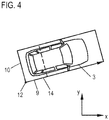
- an orientation information which comprises a (complete) bounding box 14 (cf. Fig. 4 ) with an orientation describing the yaw angle of the vehicle 3.
- the bounding box 14 is assigned, from a plurality of possible orientations corresponding to the orientations 13a to 13d, to those for which the deviation of its orientation angle ⁇ from the direction of movement of the object is minimal.
- the motion information describes the velocity of the object by velocity components in the x-direction and y-direction, so that the orientation angle ⁇ is assigned for the
- this assignment in other words a switching of the dynamics model, only takes place when an allocation criterion is met, ie as soon as the orientation can be determined with sufficient certainty.
- This is the assignment criterion is applied to the motion information and describes reaching a threshold by a measure of angular uncertainty of the direction of movement of the object.
- This measure determines the processing device 6 according to the following formula: var v x ⁇ v y 2 - 2 ⁇ covar v x . v y ⁇ v x ⁇ v y + var v y ⁇ v x 2 v x 2 + v y 2
- Var describe the variance and Covar the covariance.
- the corresponding values for the variances and covariance are calculated by using a Kalman filter as part of the object's tracking.
- FIG. 2 shows the determination of the actual orientation of the bounding box 14 again, by representing the offset of the segment 11 to a position 15 in a later measuring cycle of the sensor 5.
- the arrow 16 illustrates the direction of movement of the object in the form of a velocity vector, which is determined during the execution of the tracking algorithm using the Kalman filter. As can be seen, the arrow 16 does not point along the longitudinal axis of the vehicle 3. This offset makes it clear that the velocity vector can not be determined exactly by the tracking algorithm, but rather a certain angular uncertainty is given. Only if the measure is assessed to be small enough in the context of the assignment criterion does the additional use of the orientation information take place within the scope of the dynamics model.
- the side lengths of the bounding box 14 become a length adapted to the length of the route 10 and a multiple of the length of the route 10 described by the geometry hypothesis the route 9 determined.
- the above-described method can basically also be used if a segment 11 (I-shape) having only one segment is determined from the sensor data, that is, if the sensor 5 detects only object points 8 of a transverse or longitudinal side of the vehicle 3. Also in this case, a corresponding reference point 12 can be determined as the end point of the route, according to which a determination of a bounding box 14 with assignment of the orientation and an adaptation of the size of the bounding box 14 takes place as a function of the movement information.
- the assignment criterion is applied to a geometry information describing the geometric extension of the object. This is expedient in particular if, after one or more measuring cycles of the sensor 5, the side lengths of the vehicle 3 can be determined with sufficient accuracy, so that a statement about the orientation of the vehicle 3 is derived, again using a geometry hypothesis for the ratio of these side lengths leaves.
- the assignment of the orientation angle ⁇ then takes place analogously to the previously described embodiment, taking into account the movement information.
Landscapes
- Engineering & Computer Science (AREA)
- Physics & Mathematics (AREA)
- General Physics & Mathematics (AREA)
- Remote Sensing (AREA)
- Radar, Positioning & Navigation (AREA)
- Computer Networks & Wireless Communication (AREA)
- Theoretical Computer Science (AREA)
- Multimedia (AREA)
- Electromagnetism (AREA)
- Mechanical Engineering (AREA)
- Transportation (AREA)
- Mathematical Physics (AREA)
- Automation & Control Theory (AREA)
- Library & Information Science (AREA)
- Data Mining & Analysis (AREA)
- Databases & Information Systems (AREA)
- General Engineering & Computer Science (AREA)
- Traffic Control Systems (AREA)
- Image Analysis (AREA)
Claims (12)
- Procédé de fonctionnement d'un dispositif de traitement (6) pour des données de capteur d'au moins un capteur (5) monté dans un véhicule automobile (1), qui détecte des objets dans l'environnement du véhicule automobile (1) et dont les données de capteur décrivent des points d'objet (8) avec une information de distance, dans lequel le dispositif de traitement (6) détermine des objets à partir des données de capteur et poursuit le mouvement d'un objet classifié en tant que véhicule (3), dans lequel la poursuite de l'objet est effectuée au moyen d'un modèle dynamique qui utilise une information de déplacement décrivant le déplacement de l'objet dans deux sens de coordonnées,
caractérisé en ce
que le dispositif de traitement utilise, lors du remplissage d'un critère d'attribution appliqué sur l'information de déplacement et/ou sur une information de géométrie décrivant l'extension géométrique de l'objet dans le cadre du modèle dynamique, en outre une information d'orientation qui comprend un rectangle englobant (14) avec une orientation décrivant l'angle de lacet du véhicule (3). - Procédé selon la revendication 1
caractérisé en ce
qu'au rectangle englobant (14) est attribuée parmi plusieurs orientations possibles celle pour laquelle l'écart de son angle d'orientation (a) du sens de déplacement de l'objet est minimal. - Procédé selon la revendication 1 ou 2,
caractérisé en ce
que le critère d'attribution appliqué sur l'information de déplacement décrit une atteinte d'une valeur seuil par une mesure d'une incertitude d'angle du sens de déplacement de l'objet. - Procédé selon la revendication 3,
caractérisé en ce
que la mesure pour l'incertitude d'angle est déterminée en fonction de la variance d'au moins une vitesse dans un sens de coordonnées et/ou la covariance de vitesses dans les sens de coordonnées. - Procédé selon l'une quelconque des revendications précédentes,
caractérisé en ce
que le dispositif de traitement (6) réunit, pour la détermination de l'objet, plusieurs points d'objet (8) en un segment (11) délimité par un trajet ou plusieurs trajets (9, 10) et détermine un point de référence (12), en particulier en tant que point final du trajet ou en tant que point d'intersection de deux trajets (9, 10) du segment (11). - Procédé selon la revendication 5,
caractérisé en ce
que le critère d'attribution appliqué à l'information de géométrie décrit l'atteinte d'une valeur seuil pour un rapport de deux longueurs de trajet. - Procédé selon la revendication 5 ou 6,
caractérisé en ce
que la poursuite du déplacement de l'objet est effectuée à l'aide du point de référence (12). - Procédé selon l'une quelconque des revendications 5 à 7,
caractérisé en ce
que le point de référence décrit une position d'angle du véhicule (3). - Procédé selon l'une quelconque des revendications précédentes,
caractérisé en ce
que la grandeur du rectangle englobant (14) est adaptée en fonction de l'information d'orientation et d'une hypothèse de géométrie pour le véhicule (3). - Procédé selon l'une quelconque des revendications précédentes,
caractérisé en ce
que le dispositif de traitement (6) fournit des informations d'objet obtenues à partir de la poursuite pour un système de véhicule (7) évaluant des déplacements de véhicules (3) dans le sens transversal et longitudinal. - Procédé selon l'une quelconque des revendications précédentes,
caractérisé en ce
qu'un scanner laser et/ou une caméra temps de vol et/ou un capteur radar est utilisé en tant que capteur (5). - Véhicule automobile, comprenant un capteur (5) monté dans celui-ci pour la détection d'objets dans l'environnement du véhicule automobile (1) et pour la fourniture de données de capteur qui décrivent des points d'objet (8) présentant une information de distance, ainsi qu'un dispositif de traitement (6) pour les données de capteur qui est réalisé pour la réalisation d'un procédé selon les revendications 1 à 11.
Applications Claiming Priority (1)
| Application Number | Priority Date | Filing Date | Title |
|---|---|---|---|
| DE102016006381.5A DE102016006381B3 (de) | 2016-05-24 | 2016-05-24 | Verfahren zum Betreiben einer Verarbeitungseinrichtung für Sensordaten eines in einem Kraftfahrzeug angeordneten Sensors und Kraftfahrzeug |
Publications (2)
| Publication Number | Publication Date |
|---|---|
| EP3248852A1 EP3248852A1 (fr) | 2017-11-29 |
| EP3248852B1 true EP3248852B1 (fr) | 2018-10-24 |
Family
ID=58765730
Family Applications (1)
| Application Number | Title | Priority Date | Filing Date |
|---|---|---|---|
| EP17172191.3A Active EP3248852B1 (fr) | 2016-05-24 | 2017-05-22 | Procédé de fonctionnement d'un dispositif de traitement pour des données de capteur d'un capteur disposé dans un véhicule automobile et véhicule automobile |
Country Status (3)
| Country | Link |
|---|---|
| EP (1) | EP3248852B1 (fr) |
| DE (1) | DE102016006381B3 (fr) |
| ES (1) | ES2699501T3 (fr) |
Families Citing this family (4)
| Publication number | Priority date | Publication date | Assignee | Title |
|---|---|---|---|---|
| US11899099B2 (en) * | 2018-11-30 | 2024-02-13 | Qualcomm Incorporated | Early fusion of camera and radar frames |
| DE102019102769B4 (de) * | 2019-02-05 | 2025-05-15 | Bayerische Motoren Werke Aktiengesellschaft | Verfahren und eine Vorrichtung zur Sensordatenfusion für ein Fahrzeug |
| DE102021203497B4 (de) * | 2020-11-20 | 2024-08-14 | Volkswagen Aktiengesellschaft | Detektion und Bestimmung relevanter Größen eines Objekts mittels Ultraschallsensoren |
| DE102024116938A1 (de) * | 2024-06-17 | 2025-12-18 | Audi Aktiengesellschaft | Verfahren zur Ermittlung von Orientierungswinkeln eines Kraftfahrzeugs und Kraftfahrzeug |
Family Cites Families (3)
| Publication number | Priority date | Publication date | Assignee | Title |
|---|---|---|---|---|
| JP2009042181A (ja) * | 2007-08-10 | 2009-02-26 | Denso Corp | 推定装置 |
| DE102008055932A1 (de) * | 2008-11-05 | 2010-05-06 | Iav Gmbh Ingenieurgesellschaft Auto Und Verkehr | Verfahren zur modellbasierten Simulation eines Verhaltens eines Sensors |
| DE102014210068A1 (de) * | 2014-05-27 | 2015-12-03 | Volkswagen Aktiengesellschaft | Verfahren zum Generieren eines Umfeldmodells eines Kraftfahrzeugs, Umfeldmodell und Fahrassistenzsystem |
-
2016
- 2016-05-24 DE DE102016006381.5A patent/DE102016006381B3/de not_active Expired - Fee Related
-
2017
- 2017-05-22 EP EP17172191.3A patent/EP3248852B1/fr active Active
- 2017-05-22 ES ES17172191T patent/ES2699501T3/es active Active
Non-Patent Citations (1)
| Title |
|---|
| None * |
Also Published As
| Publication number | Publication date |
|---|---|
| ES2699501T3 (es) | 2019-02-11 |
| EP3248852A1 (fr) | 2017-11-29 |
| DE102016006381B3 (de) | 2017-10-26 |
Similar Documents
| Publication | Publication Date | Title |
|---|---|---|
| EP2561419B1 (fr) | Procédé pour déterminer le parcours sur une voie d'un véhicule | |
| DE102013113619B4 (de) | Probabilistische Zielauswahl und Gefahrbewertungsverfahren und Anwendung auf ein Kreuzungs-Kollisonswarnsystem | |
| EP1634243B1 (fr) | Procede et dispositif de localisation d'objets pour des vehicules a moteur | |
| EP1577682B1 (fr) | Système de localisation d'objets pour véhicule automobile pour identifier des procédures de changement de voie | |
| DE102010006828A1 (de) | Verfahren zur automatischen Erstellung eines Modells der Umgebung eines Fahrzeugs sowie Fahrerassistenzsystem und Fahrzeug | |
| DE19629775A1 (de) | Verfahren und Vorrichtung zur Überwachung der Umgebung eines Fahrzeugs und zur Erfassung eines Ausfalls der Überwachungsvorrichtung | |
| DE102005026386A1 (de) | Verfahren und Vorrichtung zum Bestimmen von Freiflächen in der Umgebung eines Fahrzeugs | |
| EP3248852B1 (fr) | Procédé de fonctionnement d'un dispositif de traitement pour des données de capteur d'un capteur disposé dans un véhicule automobile et véhicule automobile | |
| DE102020105192A1 (de) | Verfahren zum Detektieren bewegter Objekte in einer Fahrzeugumgebung und Kraftfahrzeug | |
| WO2003015053A1 (fr) | Procede pour determiner une voie de circulation modele | |
| WO2019162794A1 (fr) | Procédé et système pour la détection de places de stationnement appropriées pour un véhicule | |
| EP1634241B1 (fr) | Procede et dispositif de determination d'objet dans des systemes d'assistance au conducteur pour vehicules automobiles | |
| DE102013202915A1 (de) | Verfahren und Vorrichtung zum Vermessen einer Parklücke für ein Einparkassistenzsystem eines Kraftfahrzeugs | |
| DE102007049706A1 (de) | Verfahren zur Schätzung der Relativbewegung von Video-Objekten und Fahrerassistenzsystem für Kraftfahrzeuge | |
| DE102014212866A1 (de) | Verfahren zum Ermitteln eines Parkplatzes aus einer Anzahl von Messpunkten | |
| WO2023066864A1 (fr) | Procédé de contrôle de plausibilité d'une trajectoire produite sur la base de données en essaim pour un véhicule automobile fonctionnant au moins en partie de manière assistée, produit- programme d'ordinateur et système d'assistance | |
| EP3293971B1 (fr) | Procédé de mise à jour d'une section d'image | |
| WO2021078335A1 (fr) | Procédé de capture d'un objet cible | |
| DE102013214631B4 (de) | Effizientes Bereitstellen von Belegungsinformationen für das Umfeld eines Fahrzeugs | |
| WO2015090691A1 (fr) | Procédé de génération d'un modèle d'environnement d'un véhicule automobile, système d'assistance au conducteur et véhicule automobile | |
| DE102010003375B4 (de) | Umfeldbewertungssystem in einem Fahrzeug mit Sensormitteln zur Erfassung von Objekten im Umfeld des Fahrzeuges | |
| DE102019102922A1 (de) | Verfahren und Vorrichtung zur Multi-Sensor-Datenfusion für automatisierte und autonome Fahrzeuge | |
| WO2020160798A1 (fr) | Procédé et dispositif de fusion de données de capteur pour un véhicule | |
| DE102021207609A1 (de) | Verfahren zur Kennzeichnung eines Bewegungsweges | |
| DE102006039104A1 (de) | Verfahren zur Entfernungsmessung von Objekten auf von Bilddaten eines Monokamerasystems |
Legal Events
| Date | Code | Title | Description |
|---|---|---|---|
| PUAI | Public reference made under article 153(3) epc to a published international application that has entered the european phase |
Free format text: ORIGINAL CODE: 0009012 |
|
| STAA | Information on the status of an ep patent application or granted ep patent |
Free format text: STATUS: THE APPLICATION HAS BEEN PUBLISHED |
|
| AK | Designated contracting states |
Kind code of ref document: A1 Designated state(s): AL AT BE BG CH CY CZ DE DK EE ES FI FR GB GR HR HU IE IS IT LI LT LU LV MC MK MT NL NO PL PT RO RS SE SI SK SM TR |
|
| AX | Request for extension of the european patent |
Extension state: BA ME |
|
| STAA | Information on the status of an ep patent application or granted ep patent |
Free format text: STATUS: REQUEST FOR EXAMINATION WAS MADE |
|
| 17P | Request for examination filed |
Effective date: 20180215 |
|
| RBV | Designated contracting states (corrected) |
Designated state(s): AL AT BE BG CH CY CZ DE DK EE ES FI FR GB GR HR HU IE IS IT LI LT LU LV MC MK MT NL NO PL PT RO RS SE SI SK SM TR |
|
| GRAP | Despatch of communication of intention to grant a patent |
Free format text: ORIGINAL CODE: EPIDOSNIGR1 |
|
| STAA | Information on the status of an ep patent application or granted ep patent |
Free format text: STATUS: GRANT OF PATENT IS INTENDED |
|
| RIC1 | Information provided on ipc code assigned before grant |
Ipc: G01S 17/66 20060101ALI20180508BHEP Ipc: G01S 5/02 20100101ALI20180508BHEP Ipc: B60W 40/103 20120101ALI20180508BHEP Ipc: B60W 40/109 20120101ALI20180508BHEP Ipc: B60W 40/114 20120101ALI20180508BHEP Ipc: B60W 50/00 20060101ALN20180508BHEP Ipc: B60W 40/04 20060101AFI20180508BHEP Ipc: G06F 17/30 20060101ALI20180508BHEP Ipc: G01S 17/93 20060101ALI20180508BHEP Ipc: G06K 9/32 20060101ALI20180508BHEP Ipc: B60W 40/105 20120101ALI20180508BHEP Ipc: G01S 17/58 20060101ALI20180508BHEP Ipc: B60W 40/107 20120101ALI20180508BHEP Ipc: G01S 17/06 20060101ALI20180508BHEP Ipc: G01S 7/48 20060101ALI20180508BHEP Ipc: G06K 9/00 20060101ALI20180508BHEP Ipc: G01S 17/42 20060101ALI20180508BHEP Ipc: G01S 17/87 20060101ALI20180508BHEP |
|
| RIC1 | Information provided on ipc code assigned before grant |
Ipc: G01S 17/42 20060101ALI20180516BHEP Ipc: G01S 7/48 20060101ALI20180516BHEP Ipc: B60W 40/114 20120101ALI20180516BHEP Ipc: B60W 50/00 20060101ALN20180516BHEP Ipc: G01S 17/93 20060101ALI20180516BHEP Ipc: B60W 40/109 20120101ALI20180516BHEP Ipc: B60W 40/105 20120101ALI20180516BHEP Ipc: G01S 17/06 20060101ALI20180516BHEP Ipc: B60W 40/103 20120101ALI20180516BHEP Ipc: G01S 17/58 20060101ALI20180516BHEP Ipc: G06K 9/32 20060101ALI20180516BHEP Ipc: B60W 40/04 20060101AFI20180516BHEP Ipc: G01S 17/87 20060101ALI20180516BHEP Ipc: G06F 17/30 20060101ALI20180516BHEP Ipc: G06K 9/00 20060101ALI20180516BHEP Ipc: G01S 17/66 20060101ALI20180516BHEP Ipc: B60W 40/107 20120101ALI20180516BHEP Ipc: G01S 5/02 20100101ALI20180516BHEP |
|
| INTG | Intention to grant announced |
Effective date: 20180608 |
|
| GRAS | Grant fee paid |
Free format text: ORIGINAL CODE: EPIDOSNIGR3 |
|
| GRAA | (expected) grant |
Free format text: ORIGINAL CODE: 0009210 |
|
| STAA | Information on the status of an ep patent application or granted ep patent |
Free format text: STATUS: THE PATENT HAS BEEN GRANTED |
|
| AK | Designated contracting states |
Kind code of ref document: B1 Designated state(s): AL AT BE BG CH CY CZ DE DK EE ES FI FR GB GR HR HU IE IS IT LI LT LU LV MC MK MT NL NO PL PT RO RS SE SI SK SM TR |
|
| REG | Reference to a national code |
Ref country code: CH Ref legal event code: EP |
|
| REG | Reference to a national code |
Ref country code: IE Ref legal event code: FG4D Free format text: LANGUAGE OF EP DOCUMENT: GERMAN |
|
| REG | Reference to a national code |
Ref country code: AT Ref legal event code: REF Ref document number: 1056319 Country of ref document: AT Kind code of ref document: T Effective date: 20181115 |
|
| REG | Reference to a national code |
Ref country code: DE Ref legal event code: R096 Ref document number: 502017000287 Country of ref document: DE |
|
| REG | Reference to a national code |
Ref country code: ES Ref legal event code: FG2A Ref document number: 2699501 Country of ref document: ES Kind code of ref document: T3 Effective date: 20190211 |
|
| REG | Reference to a national code |
Ref country code: NL Ref legal event code: MP Effective date: 20181024 |
|
| REG | Reference to a national code |
Ref country code: LT Ref legal event code: MG4D |
|
| PG25 | Lapsed in a contracting state [announced via postgrant information from national office to epo] |
Ref country code: NL Free format text: LAPSE BECAUSE OF FAILURE TO SUBMIT A TRANSLATION OF THE DESCRIPTION OR TO PAY THE FEE WITHIN THE PRESCRIBED TIME-LIMIT Effective date: 20181024 |
|
| PG25 | Lapsed in a contracting state [announced via postgrant information from national office to epo] |
Ref country code: LV Free format text: LAPSE BECAUSE OF FAILURE TO SUBMIT A TRANSLATION OF THE DESCRIPTION OR TO PAY THE FEE WITHIN THE PRESCRIBED TIME-LIMIT Effective date: 20181024 Ref country code: FI Free format text: LAPSE BECAUSE OF FAILURE TO SUBMIT A TRANSLATION OF THE DESCRIPTION OR TO PAY THE FEE WITHIN THE PRESCRIBED TIME-LIMIT Effective date: 20181024 Ref country code: IS Free format text: LAPSE BECAUSE OF FAILURE TO SUBMIT A TRANSLATION OF THE DESCRIPTION OR TO PAY THE FEE WITHIN THE PRESCRIBED TIME-LIMIT Effective date: 20190224 Ref country code: NO Free format text: LAPSE BECAUSE OF FAILURE TO SUBMIT A TRANSLATION OF THE DESCRIPTION OR TO PAY THE FEE WITHIN THE PRESCRIBED TIME-LIMIT Effective date: 20190124 Ref country code: PL Free format text: LAPSE BECAUSE OF FAILURE TO SUBMIT A TRANSLATION OF THE DESCRIPTION OR TO PAY THE FEE WITHIN THE PRESCRIBED TIME-LIMIT Effective date: 20181024 Ref country code: HR Free format text: LAPSE BECAUSE OF FAILURE TO SUBMIT A TRANSLATION OF THE DESCRIPTION OR TO PAY THE FEE WITHIN THE PRESCRIBED TIME-LIMIT Effective date: 20181024 Ref country code: BG Free format text: LAPSE BECAUSE OF FAILURE TO SUBMIT A TRANSLATION OF THE DESCRIPTION OR TO PAY THE FEE WITHIN THE PRESCRIBED TIME-LIMIT Effective date: 20190124 Ref country code: LT Free format text: LAPSE BECAUSE OF FAILURE TO SUBMIT A TRANSLATION OF THE DESCRIPTION OR TO PAY THE FEE WITHIN THE PRESCRIBED TIME-LIMIT Effective date: 20181024 |
|
| PG25 | Lapsed in a contracting state [announced via postgrant information from national office to epo] |
Ref country code: GR Free format text: LAPSE BECAUSE OF FAILURE TO SUBMIT A TRANSLATION OF THE DESCRIPTION OR TO PAY THE FEE WITHIN THE PRESCRIBED TIME-LIMIT Effective date: 20190125 Ref country code: SE Free format text: LAPSE BECAUSE OF FAILURE TO SUBMIT A TRANSLATION OF THE DESCRIPTION OR TO PAY THE FEE WITHIN THE PRESCRIBED TIME-LIMIT Effective date: 20181024 Ref country code: PT Free format text: LAPSE BECAUSE OF FAILURE TO SUBMIT A TRANSLATION OF THE DESCRIPTION OR TO PAY THE FEE WITHIN THE PRESCRIBED TIME-LIMIT Effective date: 20190224 Ref country code: AL Free format text: LAPSE BECAUSE OF FAILURE TO SUBMIT A TRANSLATION OF THE DESCRIPTION OR TO PAY THE FEE WITHIN THE PRESCRIBED TIME-LIMIT Effective date: 20181024 Ref country code: RS Free format text: LAPSE BECAUSE OF FAILURE TO SUBMIT A TRANSLATION OF THE DESCRIPTION OR TO PAY THE FEE WITHIN THE PRESCRIBED TIME-LIMIT Effective date: 20181024 |
|
| REG | Reference to a national code |
Ref country code: DE Ref legal event code: R097 Ref document number: 502017000287 Country of ref document: DE |
|
| PG25 | Lapsed in a contracting state [announced via postgrant information from national office to epo] |
Ref country code: CZ Free format text: LAPSE BECAUSE OF FAILURE TO SUBMIT A TRANSLATION OF THE DESCRIPTION OR TO PAY THE FEE WITHIN THE PRESCRIBED TIME-LIMIT Effective date: 20181024 Ref country code: DK Free format text: LAPSE BECAUSE OF FAILURE TO SUBMIT A TRANSLATION OF THE DESCRIPTION OR TO PAY THE FEE WITHIN THE PRESCRIBED TIME-LIMIT Effective date: 20181024 |
|
| PG25 | Lapsed in a contracting state [announced via postgrant information from national office to epo] |
Ref country code: RO Free format text: LAPSE BECAUSE OF FAILURE TO SUBMIT A TRANSLATION OF THE DESCRIPTION OR TO PAY THE FEE WITHIN THE PRESCRIBED TIME-LIMIT Effective date: 20181024 Ref country code: SK Free format text: LAPSE BECAUSE OF FAILURE TO SUBMIT A TRANSLATION OF THE DESCRIPTION OR TO PAY THE FEE WITHIN THE PRESCRIBED TIME-LIMIT Effective date: 20181024 Ref country code: EE Free format text: LAPSE BECAUSE OF FAILURE TO SUBMIT A TRANSLATION OF THE DESCRIPTION OR TO PAY THE FEE WITHIN THE PRESCRIBED TIME-LIMIT Effective date: 20181024 Ref country code: SM Free format text: LAPSE BECAUSE OF FAILURE TO SUBMIT A TRANSLATION OF THE DESCRIPTION OR TO PAY THE FEE WITHIN THE PRESCRIBED TIME-LIMIT Effective date: 20181024 |
|
| PLBE | No opposition filed within time limit |
Free format text: ORIGINAL CODE: 0009261 |
|
| STAA | Information on the status of an ep patent application or granted ep patent |
Free format text: STATUS: NO OPPOSITION FILED WITHIN TIME LIMIT |
|
| 26N | No opposition filed |
Effective date: 20190725 |
|
| PG25 | Lapsed in a contracting state [announced via postgrant information from national office to epo] |
Ref country code: SI Free format text: LAPSE BECAUSE OF FAILURE TO SUBMIT A TRANSLATION OF THE DESCRIPTION OR TO PAY THE FEE WITHIN THE PRESCRIBED TIME-LIMIT Effective date: 20181024 |
|
| PG25 | Lapsed in a contracting state [announced via postgrant information from national office to epo] |
Ref country code: MC Free format text: LAPSE BECAUSE OF FAILURE TO SUBMIT A TRANSLATION OF THE DESCRIPTION OR TO PAY THE FEE WITHIN THE PRESCRIBED TIME-LIMIT Effective date: 20181024 |
|
| REG | Reference to a national code |
Ref country code: BE Ref legal event code: MM Effective date: 20190531 |
|
| PG25 | Lapsed in a contracting state [announced via postgrant information from national office to epo] |
Ref country code: LU Free format text: LAPSE BECAUSE OF NON-PAYMENT OF DUE FEES Effective date: 20190522 |
|
| PG25 | Lapsed in a contracting state [announced via postgrant information from national office to epo] |
Ref country code: TR Free format text: LAPSE BECAUSE OF FAILURE TO SUBMIT A TRANSLATION OF THE DESCRIPTION OR TO PAY THE FEE WITHIN THE PRESCRIBED TIME-LIMIT Effective date: 20181024 |
|
| PG25 | Lapsed in a contracting state [announced via postgrant information from national office to epo] |
Ref country code: IE Free format text: LAPSE BECAUSE OF NON-PAYMENT OF DUE FEES Effective date: 20190522 |
|
| PG25 | Lapsed in a contracting state [announced via postgrant information from national office to epo] |
Ref country code: BE Free format text: LAPSE BECAUSE OF NON-PAYMENT OF DUE FEES Effective date: 20190531 |
|
| PG25 | Lapsed in a contracting state [announced via postgrant information from national office to epo] |
Ref country code: LI Free format text: LAPSE BECAUSE OF NON-PAYMENT OF DUE FEES Effective date: 20200531 Ref country code: CH Free format text: LAPSE BECAUSE OF NON-PAYMENT OF DUE FEES Effective date: 20200531 |
|
| PG25 | Lapsed in a contracting state [announced via postgrant information from national office to epo] |
Ref country code: CY Free format text: LAPSE BECAUSE OF FAILURE TO SUBMIT A TRANSLATION OF THE DESCRIPTION OR TO PAY THE FEE WITHIN THE PRESCRIBED TIME-LIMIT Effective date: 20181024 |
|
| PG25 | Lapsed in a contracting state [announced via postgrant information from national office to epo] |
Ref country code: MT Free format text: LAPSE BECAUSE OF FAILURE TO SUBMIT A TRANSLATION OF THE DESCRIPTION OR TO PAY THE FEE WITHIN THE PRESCRIBED TIME-LIMIT Effective date: 20181024 Ref country code: HU Free format text: LAPSE BECAUSE OF FAILURE TO SUBMIT A TRANSLATION OF THE DESCRIPTION OR TO PAY THE FEE WITHIN THE PRESCRIBED TIME-LIMIT; INVALID AB INITIO Effective date: 20170522 |
|
| PG25 | Lapsed in a contracting state [announced via postgrant information from national office to epo] |
Ref country code: MK Free format text: LAPSE BECAUSE OF FAILURE TO SUBMIT A TRANSLATION OF THE DESCRIPTION OR TO PAY THE FEE WITHIN THE PRESCRIBED TIME-LIMIT Effective date: 20181024 |
|
| P01 | Opt-out of the competence of the unified patent court (upc) registered |
Effective date: 20230530 |
|
| REG | Reference to a national code |
Ref country code: AT Ref legal event code: MM01 Ref document number: 1056319 Country of ref document: AT Kind code of ref document: T Effective date: 20220522 |
|
| PG25 | Lapsed in a contracting state [announced via postgrant information from national office to epo] |
Ref country code: AT Free format text: LAPSE BECAUSE OF NON-PAYMENT OF DUE FEES Effective date: 20220522 |
|
| PGFP | Annual fee paid to national office [announced via postgrant information from national office to epo] |
Ref country code: DE Payment date: 20250531 Year of fee payment: 9 |
|
| PGFP | Annual fee paid to national office [announced via postgrant information from national office to epo] |
Ref country code: GB Payment date: 20250524 Year of fee payment: 9 Ref country code: ES Payment date: 20250602 Year of fee payment: 9 |
|
| PGFP | Annual fee paid to national office [announced via postgrant information from national office to epo] |
Ref country code: IT Payment date: 20250529 Year of fee payment: 9 |
|
| PGFP | Annual fee paid to national office [announced via postgrant information from national office to epo] |
Ref country code: FR Payment date: 20250520 Year of fee payment: 9 |