EP3248929A1 - Zylinderkopfkörper, einzylinderbolzensystem und kran - Google Patents
Zylinderkopfkörper, einzylinderbolzensystem und kran Download PDFInfo
- Publication number
- EP3248929A1 EP3248929A1 EP16758479.6A EP16758479A EP3248929A1 EP 3248929 A1 EP3248929 A1 EP 3248929A1 EP 16758479 A EP16758479 A EP 16758479A EP 3248929 A1 EP3248929 A1 EP 3248929A1
- Authority
- EP
- European Patent Office
- Prior art keywords
- cylinder head
- head body
- branch
- cylinder
- bodies
- Prior art date
- Legal status (The legal status is an assumption and is not a legal conclusion. Google has not performed a legal analysis and makes no representation as to the accuracy of the status listed.)
- Granted
Links
Images


Classifications
-
- B—PERFORMING OPERATIONS; TRANSPORTING
- B66—HOISTING; LIFTING; HAULING
- B66C—CRANES; LOAD-ENGAGING ELEMENTS OR DEVICES FOR CRANES, CAPSTANS, WINCHES, OR TACKLES
- B66C23/00—Cranes comprising essentially a beam, boom, or triangular structure acting as a cantilever and mounted for translatory of swinging movements in vertical or horizontal planes or a combination of such movements, e.g. jib-cranes, derricks, tower cranes
- B66C23/62—Constructional features or details
- B66C23/64—Jibs
- B66C23/68—Jibs foldable or otherwise adjustable in configuration
-
- B—PERFORMING OPERATIONS; TRANSPORTING
- B66—HOISTING; LIFTING; HAULING
- B66C—CRANES; LOAD-ENGAGING ELEMENTS OR DEVICES FOR CRANES, CAPSTANS, WINCHES, OR TACKLES
- B66C23/00—Cranes comprising essentially a beam, boom, or triangular structure acting as a cantilever and mounted for translatory of swinging movements in vertical or horizontal planes or a combination of such movements, e.g. jib-cranes, derricks, tower cranes
- B66C23/62—Constructional features or details
- B66C23/64—Jibs
- B66C23/70—Jibs constructed of sections adapted to be assembled to form jibs or various lengths
- B66C23/701—Jibs constructed of sections adapted to be assembled to form jibs or various lengths telescopic
- B66C23/708—Jibs constructed of sections adapted to be assembled to form jibs or various lengths telescopic locking devices for telescopic jibs
-
- F—MECHANICAL ENGINEERING; LIGHTING; HEATING; WEAPONS; BLASTING
- F15—FLUID-PRESSURE ACTUATORS; HYDRAULICS OR PNEUMATICS IN GENERAL
- F15B—SYSTEMS ACTING BY MEANS OF FLUIDS IN GENERAL; FLUID-PRESSURE ACTUATORS, e.g. SERVOMOTORS; DETAILS OF FLUID-PRESSURE SYSTEMS, NOT OTHERWISE PROVIDED FOR
- F15B15/00—Fluid-actuated devices for displacing a member from one position to another; Gearing associated therewith
- F15B15/08—Characterised by the construction of the motor unit
- F15B15/14—Characterised by the construction of the motor unit of the straight-cylinder type
- F15B15/1423—Component parts; Constructional details
-
- F—MECHANICAL ENGINEERING; LIGHTING; HEATING; WEAPONS; BLASTING
- F15—FLUID-PRESSURE ACTUATORS; HYDRAULICS OR PNEUMATICS IN GENERAL
- F15B—SYSTEMS ACTING BY MEANS OF FLUIDS IN GENERAL; FLUID-PRESSURE ACTUATORS, e.g. SERVOMOTORS; DETAILS OF FLUID-PRESSURE SYSTEMS, NOT OTHERWISE PROVIDED FOR
- F15B15/00—Fluid-actuated devices for displacing a member from one position to another; Gearing associated therewith
- F15B15/08—Characterised by the construction of the motor unit
- F15B15/14—Characterised by the construction of the motor unit of the straight-cylinder type
- F15B15/1423—Component parts; Constructional details
- F15B15/1428—Cylinders
-
- B—PERFORMING OPERATIONS; TRANSPORTING
- B66—HOISTING; LIFTING; HAULING
- B66C—CRANES; LOAD-ENGAGING ELEMENTS OR DEVICES FOR CRANES, CAPSTANS, WINCHES, OR TACKLES
- B66C23/00—Cranes comprising essentially a beam, boom, or triangular structure acting as a cantilever and mounted for translatory of swinging movements in vertical or horizontal planes or a combination of such movements, e.g. jib-cranes, derricks, tower cranes
- B66C23/62—Constructional features or details
-
- B—PERFORMING OPERATIONS; TRANSPORTING
- B66—HOISTING; LIFTING; HAULING
- B66C—CRANES; LOAD-ENGAGING ELEMENTS OR DEVICES FOR CRANES, CAPSTANS, WINCHES, OR TACKLES
- B66C23/00—Cranes comprising essentially a beam, boom, or triangular structure acting as a cantilever and mounted for translatory of swinging movements in vertical or horizontal planes or a combination of such movements, e.g. jib-cranes, derricks, tower cranes
- B66C23/62—Constructional features or details
- B66C23/64—Jibs
- B66C23/66—Outer or upper end constructions
-
- B—PERFORMING OPERATIONS; TRANSPORTING
- B66—HOISTING; LIFTING; HAULING
- B66C—CRANES; LOAD-ENGAGING ELEMENTS OR DEVICES FOR CRANES, CAPSTANS, WINCHES, OR TACKLES
- B66C23/00—Cranes comprising essentially a beam, boom, or triangular structure acting as a cantilever and mounted for translatory of swinging movements in vertical or horizontal planes or a combination of such movements, e.g. jib-cranes, derricks, tower cranes
- B66C23/62—Constructional features or details
- B66C23/64—Jibs
- B66C23/70—Jibs constructed of sections adapted to be assembled to form jibs or various lengths
- B66C23/701—Jibs constructed of sections adapted to be assembled to form jibs or various lengths telescopic
-
- B—PERFORMING OPERATIONS; TRANSPORTING
- B66—HOISTING; LIFTING; HAULING
- B66C—CRANES; LOAD-ENGAGING ELEMENTS OR DEVICES FOR CRANES, CAPSTANS, WINCHES, OR TACKLES
- B66C23/00—Cranes comprising essentially a beam, boom, or triangular structure acting as a cantilever and mounted for translatory of swinging movements in vertical or horizontal planes or a combination of such movements, e.g. jib-cranes, derricks, tower cranes
- B66C23/62—Constructional features or details
- B66C23/64—Jibs
- B66C23/70—Jibs constructed of sections adapted to be assembled to form jibs or various lengths
- B66C23/701—Jibs constructed of sections adapted to be assembled to form jibs or various lengths telescopic
- B66C23/705—Jibs constructed of sections adapted to be assembled to form jibs or various lengths telescopic telescoped by hydraulic jacks
-
- F—MECHANICAL ENGINEERING; LIGHTING; HEATING; WEAPONS; BLASTING
- F15—FLUID-PRESSURE ACTUATORS; HYDRAULICS OR PNEUMATICS IN GENERAL
- F15B—SYSTEMS ACTING BY MEANS OF FLUIDS IN GENERAL; FLUID-PRESSURE ACTUATORS, e.g. SERVOMOTORS; DETAILS OF FLUID-PRESSURE SYSTEMS, NOT OTHERWISE PROVIDED FOR
- F15B15/00—Fluid-actuated devices for displacing a member from one position to another; Gearing associated therewith
- F15B15/08—Characterised by the construction of the motor unit
- F15B15/14—Characterised by the construction of the motor unit of the straight-cylinder type
- F15B15/16—Characterised by the construction of the motor unit of the straight-cylinder type of the telescopic type
Definitions
- the invention relates to the field of engineering machinery, especially a cylinder head body, a single cylinder bolt system and a crane.
- a single cylinder bolt system is a device built into a telescopic boom of the crane to assist the telescopic cylinder to realize the telescopic function of the telescopic boom of the crane.
- a single cylinder bolt system mainly consists of a telescopic boom and a cylinder, wherein main functional components for a hoist boom to realize extension and contraction include a cylinder head, a cylinder head body, a slide rail, a rail bracket, a boom pin, a cylinder pin, a dovetail groove, a driving cylinder, a detection switch and other auxiliary facilities.
- the cylinder head is in a certain position of a cylinder barrel or a piston rod of the telescopic cylinder for controlling coupling and decoupling between the telescopic cylinder and the telescopic boom and between telescopic booms.
- the cylinder head mainly comprises a cylinder head body, a boom pin driving device, a cylinder pin driving device, a driving cylinder, a position detection block and so on.
- the cylinder head body is directly connected to the cylinder, for assembling the boom pin driving device, the cylinder pin driving device and carriers of other components, which is a major component of the cylinder head.
- the slide rail is assembled on the telescopic cylinder. It has a function of maintaining the position of the telescopic cylinder in the hoist boom slide and preventing the telescopic cylinder from spinning or flexing in the hoist boom.
- the rail bracket is also a constituent part of the telescopic cylinder, for assembling the slide rail, and it is generally welded on the cylinder barrel along the axial direction, and one telescopic cylinder has a number of rail brackets.
- the cylinder pin is a pin on the cylinder, which has a function of locking the cylinder and the telescopic boom together. In existing products, each cylinder head generally has two or four cylinder pins.
- the boom pin is a pin on the telescopic boom, which has a function of locking telescopic booms together.
- each cylinder head generally has one or two boom pins.
- the cylinder pin rail is mounted within the cylinder head, whose structure is provided with a slide, along which the cylinder pin moves to realize telescopic motion of the cylinder pin.
- the boom pin rail is mounted within the cylinder head, whose structure is provided with a slide, along which the boom pin moves to realize unlocking motion of boom pin.
- the driving cylinder is an actuator for realizing motion of the boom pin and the cylinder pin.
- the cylinder barrel of the telescopic cylinder is welded with a flange connected to an end face flange of the cylinder body, and the cylinder barrel is assembled or welded with a rail bracket, so that the cylinder head body must be inserted into the cylinder barrel when assembled, then the cylinder head body and the flange are connected, then the rail bracket is assembled or welded, the slide rail is assembled on the rail bracket, and assembling of the cylinder is finished.
- cylinder heads may not be supplied in time, causing failure in sequential mounting.
- dismounting is inconvenient during maintenance of the cylinder head body. If the slide rail and the cylinder barrel are connected in an assembling way, dismounting is more convenient, but it is still time-consuming.
- the rail bracket and the cylinder barrel are welded together, because in this way, connection of the slide rail and the cylinder is more firm, which results in that the cylinder head body cannot be dismounted for maintenance.
- FIG. 1 is a schematic view of the structure of an existing single-cylinder-bolt cylinder head body mounted on a telescopic cylinder.
- the cylinder head body a3 mounted on the cylinder barrel a1 is inserted from the bottom of the cylinder.
- the end face flange a4 of the cylinder head body a3 is connected to the flange bolt a5 welded on the cylinder barrel.
- the rail bracket a6 is assembled or welded, and then the slide rail a2 is assembled, this assembling sequence cannot be reversed.
- the cylinder head body a8 assembled on the cylinder rod a9 should be inserted by the cylinder rod a9 before the cylinder rod a9 is mounted in the cylinder barrel a1, and then connected to the cylinder barrel a1, such mounting sequence cannot be reversed, either, or it cannot be assembled because of influence of the end face flange a7 and the earring a10.
- the present invention provides a cylinder head body which is not restricted by the assembling sequence, to realize flexible mounting, convenient dismounting and maintenance, which is highly reliable.
- the present invention provides a cylinder head body which comprises at least two branch bodies.
- a cooperative positioning structure and a fixed connection structure are provided between two adjacent branch bodies of cylinder head body of the at least two branch bodies of cylinder head body.
- the branch body of cylinder head body has a cylindrical branch body structure.
- the cylindrical branch body structures of the at least two branch bodies of cylinder head body are cooperatively positioned by means of the cooperative positioning structure, and are detachably connected by means of the fixed connection structure to form a barrel.
- the cylinder head body is composed of at least two branch bodies of cylinder head body, which are cooperatively positioned and detachably connected by the cooperative positioning structure and the fixed connection structure, respectively.
- the cylinder head body may be dismounted into branch body structures, assembling of which is not restricted by the assembling sequence, which avoids influencing assembling of other components of the cylinder due to insufficient supply of cylinder head bodies, improves assembling efficiency and production efficiency, facilitates dismounting and maintenance of the cylinder head body, and saves maintenance cost.
- the cooperative positioning structure comprises a rabbet cooperatively formed by a concave rabbet and a convex rabbet provided on the butting end faces of two adjacent branch bodies of cylinder head body of the at least two branch bodies of cylinder head body.
- the cooperative positioning structure is a rabbet for centering and connection, positioning by the rabbet is accurate, such that branch bodies of cylinder head body are stressed axially into one piece, and two sides are stressed uniformly when stressed axially. Moreover, the rabbet is easy to obtain and has favorable feasibility.
- the cooperative positioning structure comprises a plurality of cooperating bosses and grooves respectively provided on the butting end faces of two adjacent branch bodies of cylinder head body of the at least two branch bodies of cylinder head body.
- the cooperative positioning structure is formed by a plurality of cooperating bosses and grooves.
- the bosses and grooves are cooperatively positioned, such that the cylinder head is stressed axially into one piece.
- bosses and grooves are easy to machine and have favorable feasibility.
- the plurality of cooperating bosses and grooves are provided equally spaced apart along the axial direction of the cylinder head body.
- the plurality of cooperating bosses and grooves are provided equally spaced apart on the butting end faces, such that the barrel is stressed uniformly at both sides when stressed axially.
- the fixed connection structure comprises a connection plate provided on two adjacent branch bodies of cylinder head body of the at least two branch bodies of cylinder head body.
- the connection plate is provided with a bolt hole. Two adjacent branch bodies of cylinder head body are detachably connected by a bolt passing through the bolt hole.
- the fixed connection structure comprises a connection plate.
- the bolt and the connection plate firmly connect the branch bodies of cylinder head body, such that the cylinder head body can bear a force perpendicular to the butting end faces.
- Bolted connection is easy to realize and has a high connection stability.
- the fixed connection structure comprises a first buckle and a second buckle respectively provided on two adjacent branch bodies of cylinder head body of the at least two branch bodies of cylinder head body. Two adjacent branch bodies of cylinder head body are detachably connected by buckling the first buckle on the second buckle.
- the fixed connection structure is a buckle structure.
- the branch bodies of cylinder head body are detachably connected by the buckles, such that the cylinder head body can bear a force perpendicular to the butting end faces.
- Buckle connection is easy to realize and has a high connection stability.
- branch bodies of cylinder head body have a branch body structure of end face flange.
- End face flange branch bodies of at least two branch bodies of cylinder head body are cooperatively positioned by means of the cooperative positioning structure and are detachably connected by means of the fixed connection structure to form an end face flange.
- the barrel protrudes by a predetermined length beyond the end face flange.
- the barrel protrudes, by a predetermined length, over the end face flange, the barrel is inserted in the groove of the flange welded on the cylinder barrel. Then the end face flange is connected to the flange welded on the cylinder barrel by a bolt, to better enable the branch bodies of cylinder head body to bear an axial force and a force perpendicular to the butting end faces of the branch bodies of cylinder head body, which further improves stability and reliability of connection and significantly enhances the tightness and stability of the mating between the cylinder head and the cylinder.
- the cooperative positioning structure comprises a bolt shaft and a bolt hole provided on the butting end faces of two adjacent branch bodies of end face flange of at least two branch bodies of cylinder head body.
- the bolt shaft is inserted into the bolt hole to realize cooperative mounting.
- the cooperative positioning structure further comprises a bolt hole provided on the butting end faces. Positioning and mating of the bolt hole and the bolt shaft make positioning of the branch bodies of cylinder head body more accurate, and further ensure that the butting end face is stressed uniformly at both sides when the branch bodies of cylinder head body are stressed axially.
- the at least two branch bodies of cylinder head body comprise a first branch body of cylinder head body and a second branch body of cylinder head body.
- the first branch body of cylinder head body and the second branch body of cylinder head body respectively have a first cylindrical branch body and a second cylindrical branch body.
- the cooperative positioning structure comprises a rabbet cooperatively formed by a concave rabbet and a convex rabbet respectively provided on the butting end faces of the first cylindrical branch body and the second cylindrical branch body.
- the fixed connection structure comprises a connection plate provided on the first cylindrical branch body and the second cylindrical branch body.
- the connection plate is provided with a bolt hole.
- the first cylindrical branch body and the second cylindrical branch body are cooperatively positioned by the rabbet and are detachably connected by means of a bolt passing through the bolt hole to form a barrel together.
- the cylinder head body is composed of two branch body structures, i.e., a first branch body of cylinder head body and a second branch body of cylinder head body in a dismountable way.
- the first branch body of cylinder head body and the second branch body of cylinder head body are cooperatively positioned by means of the rabbet and are stably, reliably, fixedly connected by means of the bolt and the connection plate.
- Two branch body structures have two butting end faces.
- the cooperative positioning structure and the fixed connection structure are relatively simple. Correspondingly, production cost and dismounting cost are relatively low.
- the present invention further provides a single cylinder bolt system having a cylinder head which comprises the abovementioned cylinder head body.
- the cylinder head body is especially suitable for a cylinder head in a single cylinder bolt system.
- the present invention further provides a crane having the abovementioned single cylinder bolt system.
- the crane having the abovementioned single cylinder bolt system correspondingly has the abovementioned advantageous technical effects.
- the present invention provides a cylinder head body, which is composed of at least two branch bodies of cylinder head body in a dismountable way, which are cooperatively positioned and detachably connected by a cooperative positioning structure and a fixed connection structure, respectively, such that the cylinder head body may be dismounted into branch body structures during assembling, assembling manner thereof is not restricted by traditional assembling sequence, assembling efficiency and production efficiency are improved.
- the cylinder head body is easy to dismount and maintain, which saves maintenance cost.
- the single cylinder bolt system and the crane provided by the present invention correspondingly have the abovementioned advantageous technical effects.
- Embodiments of the present invention are used for further explaining the inventive concept, the technical problem to be solved, the technical features constituting the technical solution and the technical effects of the present invention. It is necessary to explain that, description of these embodiments does not constitute delimitations of the present invention. Besides, the technical features involved in the embodiments of the present invention described below may be combined with each other as long as they do not conflict with each other.
- the present invention designs a cylinder head body, which is composed of at least two branch bodies of cylinder head body in a dismountable way, which are cooperatively positioned and detachably connected by a cooperative positioning structure and a fixed connection structure, respectively, such that the cylinder head body may be dismounted into branch structures during assembling, assembling manner thereof is not restricted by traditional assembling sequence, assembling efficiency and production efficiency are improved.
- the cylinder head body is easy to dismount and maintain, which saves maintenance cost.
- FIG. 2 is a schematic view of the structure of an embodiment of a cylinder head body of the present invention.
- the cylinder head body is composed of two branch body structures, i.e., a first branch body 1 of cylinder head body and a second branch body 2 of cylinder head body.
- a cooperative positioning structure and a fixed connection structure are provided between the first branch body 1 of cylinder head body and the second branch body 2 of cylinder head body.
- the first branch body 1 of cylinder head body and the second branch body 2 of cylinder head body respectively have a first cylindrical branch body 31 and a second cylindrical branch body 32.
- the first cylindrical branch body 31 and the second cylindrical branch body 32 are cooperatively positioned by means of the cooperative positioning structure and are detachably connected by means of the fixed connection structure to form a barrel 3 together.
- the cylinder head body is composed of the first branch body 1 of cylinder head body and the second branch body 2 of cylinder head body in a dismountable way, which are cooperatively positioned and detachably connected by the cooperative positioning structure and the fixed connection structure, respectively.
- the cylinder head body may be mounted at both sides of the welded flange, which avoids that insertion direction and mounting side of traditional one-piece cylinder head bodies are fixed due to influence of the welded flange, and makes the assembling direction of the cylinder head body flexible.
- the cylinder head body is not influenced by other components along the axial direction of the cylinder barrel during assembling and disassembling, and it has an advantage of convenient assembling, disassembling and maintenance. Besides, during assembling of the cylinder, the cylinder head body won't influence assembling of other components, which avoids influencing assembling of other components due to insufficient supply of cylinder head bodies and improves production efficiency.
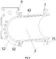
- the cooperative positioning structure comprises a rabbet 4 cooperatively formed by a concave rabbet 41 and a convex rabbet 42 respectively provided on the butting end faces of the first cylindrical branch body 31 and the second cylindrical branch body 32.
- the cooperative positioning structure uses a rabbet 4 for centering and connection. Positioning of the rabbet 4 is accurate, such that the first branch body 1 of cylinder head body and the second branch body 2 of cylinder head body are stressed axially into one piece, and the butting end faces of the first cylindrical branch body 31 and the second cylindrical branch body 32 are stressed uniformly at two sides when stressed axially, and the rabbet 4 is a connection device that is easy to machine and has favorable feasibility.
- the cooperative positioning structure may also be opposing concave and convex rabbet structures respectively provided on the two butting end faces of the first cylindrical branch body 31 and the second cylindrical branch body 32.
- the cooperative positioning structure may also be a plurality of cooperating bosses and grooves respectively provided on the butting end faces of the first cylindrical branch body 31 and the second cylindrical branch body 32.
- the bosses and grooves are cooperatively positioned, such that the first branch body 1 of cylinder head body and the second branch body 2 of cylinder head body are stressed axially into one piece.
- bosses and grooves are easy to machine and have favorable feasibility.
- the plurality of bosses and grooves are provided equally or not equally spaced apart along the axial direction of the cylinder head body.
- Equally-spaced configuration is a preferred embodiment, which enables both sides of the butting end faces to be uniformly stressed when the first cylindrical branch body 31 and the second cylindrical branch body 32 are stressed axially.
- the cooperative positioning structure may also be other conventional devices that can realize cooperating positioning.
- the fixed connection structure comprises a connection plate 7 provided on the first cylindrical branch body 31 and the second cylindrical branch body 32.
- the connection plate 7 is provided with a bolt hole 71.
- the first branch body 1 of cylinder head body and the second branch body 2 of cylinder head body are cooperatively positioned by the rabbet 4 and are detachably connected by means of a bolt 8 passing through the bolt hole 71 to form a barrel 3 together.
- the bolt 8 and the connection plate 7 firmly connect the first branch body 1 of cylinder head body and the second branch body 2 of cylinder head body, such that the first branch body 1 of cylinder head body and the second branch body 2 of cylinder head body can bear a force perpendicular to the butting end faces.
- the fixed connection structure may also comprise a first buckle and a second buckle respectively provided on the first branch body 1 of cylinder head body and the second branch body 2 of cylinder head body.
- the first branch body 1 of cylinder head body and the second branch body 2 of cylinder head body are detachably connected by buckling the first buckle on the second buckle.
- the first buckle and the second buckle firmly connect the first branch body 1 of cylinder head body and the second branch body 2 of cylinder head body, such that the first branch body 1 of cylinder head body and the second branch body 2 of cylinder head body can also bear a force perpendicular to the butting end faces.
- buckle connection is easy to realize and has a high connection stability.
- the fixed connection structure may also be other conventional devices that can realize fixed connection.
- the first branch body 1 of cylinder head body and the second branch body 2 of cylinder head body respectively have a first branch body of end face flange 51 and a second branch body of end face flange 52 which are cooperatively positioned by means of the cooperative positioning structure and are detachably connected by means of the fixed connection structure to form an end face flange 5.
- the barrel 3 protrudes by a predetermined length beyond the end face flange 5.
- the barrel 3 is machined such as to protrude, by a predetermined length, over the end face flange 5, the barrel 3 is inserted in the groove of the flange welded on the barrel 3.
- the end face flange 5 is connected to the flange welded on the cylinder barrel by a bolt, to better enable the first branch body 1 of cylinder head body and the second branch body 2 of cylinder head body to bear an axial force and a force perpendicular to the butting end faces of the first branch body 1 of cylinder head body and the second branch body 2 of cylinder head body, which further improves stability and reliability of connection of the cylinder head body and thus enhances the tightness and stability of the mating between the cylinder head and the cylinder. Further, as shown by FIGS.
- the cooperative positioning structure further comprises a bolt shaft 6 and a bolt hole 9 provided on the butting end faces of the first branch body of end face flange 51 and the second branch body of end face flange 52.
- the bolt shaft 6 is inserted into the bolt hole 9 to realize cooperative mounting.
- Positioning and mating of the bolt hole 9 and the bolt shaft 6 make positioning of the first branch body 1 of cylinder head body and the second branch body 2 of cylinder head body more accurate, and further ensure that the butting end faces are stressed uniformly at both sides when the first branch body 1 of cylinder head body and the second branch body 2 of cylinder head body are stressed axially, further improving the connection stability and reliability of the cylinder head body.
- the bolt shaft 6 may be directly welded on the butting end face of the first branch body of end face flange 51 or the second branch body of end face flange 52, so as to make positioning and mounting more convenient and rapid.
- the first branch body 1 of cylinder head body and the second branch body 2 of cylinder head body are oppositely butted at both sides of the cylinder barrel, the concave rabbet 41 and the convex rabbet 42 of the first branch body 1 of cylinder head body and the second branch body 2 of cylinder head body are connected by insertion, at the same time, the bolt shaft 6 and the bolt hole 9 are cooperatively mounted in alignment, wherein the bolt shaft 6 is first put into the bolt hole 9 of either one of the first branch body of end face flange 51 and the second branch body of end face flange 52 and then it is mounted in cooperation with the bolt hole 9 of the other one; then the bolt 8 and the bolt hole 71 firmly connect the first branch body 1 of cylinder head body and the second branch body 2 of cylinder head body into one piece; finally, the barrel 3 which protrudes over the end face flange 5 is inserted in the groove of the flange welded on the cylinder barrel, and the end face flange
- the present invention further provides a single cylinder bolt system having a cylinder head which comprises the abovementioned cylinder head body.
- the cylinder head body of the present invention is not restricted by the assembling sequence, which realizes flexible mounting, convenient dismounting and maintenance, and is highly reliable.
- the single cylinder bolt system provided by the present invention has the abovementioned advantageous technical effects and thus will not be repeated here.
- the present invention further provides a crane.
- the crane has a single cylinder bolt system as described above.
- the cylinder head of the single cylinder bolt system of the present invention is not restricted by the assembling sequence during mounting and dismounting process of the cylinder head body, which realizes flexible mounting, convenient dismounting and maintenance, and is highly reliable.
- the crane provided by the present invention has the abovementioned advantageous technical effects and thus will not be repeated here.
- the cylinder head body may also be spliced into an one-piece structure by a plurality of branch body structures of cylinder head body (for example, three) in a dismountable way, or, butting may be realized by other positioning and fastening manners.
- a plurality of branch body structures of cylinder head body for example, three
- butting may be realized by other positioning and fastening manners.
Landscapes
- Engineering & Computer Science (AREA)
- Mechanical Engineering (AREA)
- Physics & Mathematics (AREA)
- Fluid Mechanics (AREA)
- General Engineering & Computer Science (AREA)
- Cylinder Crankcases Of Internal Combustion Engines (AREA)
- Actuator (AREA)
- Connection Of Plates (AREA)
Applications Claiming Priority (2)
| Application Number | Priority Date | Filing Date | Title |
|---|---|---|---|
| CN201510095381.0A CN104649158B (zh) | 2015-03-03 | 2015-03-03 | 缸头体、单缸插销系统及起重机 |
| PCT/CN2016/075395 WO2016138864A1 (zh) | 2015-03-03 | 2016-03-03 | 缸头体、单缸插销系统及起重机 |
Publications (3)
| Publication Number | Publication Date |
|---|---|
| EP3248929A1 true EP3248929A1 (de) | 2017-11-29 |
| EP3248929A4 EP3248929A4 (de) | 2018-10-24 |
| EP3248929B1 EP3248929B1 (de) | 2021-05-12 |
Family
ID=53240880
Family Applications (1)
| Application Number | Title | Priority Date | Filing Date |
|---|---|---|---|
| EP16758479.6A Active EP3248929B1 (de) | 2015-03-03 | 2016-03-03 | Zylinderkopfkörper, einzylinderbolzensystem und kran |
Country Status (7)
| Country | Link |
|---|---|
| US (1) | US10465725B2 (de) |
| EP (1) | EP3248929B1 (de) |
| CN (1) | CN104649158B (de) |
| AU (1) | AU2016228017B2 (de) |
| CA (1) | CA2976304C (de) |
| RU (1) | RU2668765C1 (de) |
| WO (1) | WO2016138864A1 (de) |
Families Citing this family (4)
| Publication number | Priority date | Publication date | Assignee | Title |
|---|---|---|---|---|
| CN104649158B (zh) | 2015-03-03 | 2017-08-08 | 徐州重型机械有限公司 | 缸头体、单缸插销系统及起重机 |
| CN106371500B (zh) * | 2015-07-21 | 2019-10-29 | 联想(北京)有限公司 | 一种连接装置及包括该连接装置的电子设备 |
| CN114619226B (zh) * | 2020-12-14 | 2023-12-08 | 徐州徐工液压件有限公司 | 液压缸试验台的插拔销装置 |
| CN113682980A (zh) * | 2021-09-06 | 2021-11-23 | 徐州徐工随车起重机有限公司 | 一种折臂汽车起重机用六节伸缩臂装置 |
Family Cites Families (19)
| Publication number | Priority date | Publication date | Assignee | Title |
|---|---|---|---|---|
| US4373851A (en) * | 1980-10-09 | 1983-02-15 | Confoey Richard J | Bulldozer and backhoe lock device |
| US4395192A (en) * | 1981-01-19 | 1983-07-26 | The Warner & Swasey Company | Boom cylinder |
| US4417644A (en) * | 1981-06-15 | 1983-11-29 | Brogard Paul D | Anti-theft device and method for deterring theft of mobile equipment |
| DE29824453U1 (de) * | 1997-05-28 | 2001-03-01 | Mannesmann AG, 40213 Düsseldorf | Kran mit einem Teleskopausleger |
| RU2213043C2 (ru) * | 2001-04-26 | 2003-09-27 | Закрытое акционерное общество "Национальная компания Уралтерминалмаш" | Стойка поворотная опорно-поворотного устройства краноманипуляторной установки |
| JP3924459B2 (ja) * | 2001-12-12 | 2007-06-06 | 未来工業株式会社 | 管接続具 |
| JP2004116318A (ja) * | 2002-09-24 | 2004-04-15 | Niigata Power Systems Co Ltd | 内燃機関のシリンダライナ抜き出し装置 |
| US6874338B1 (en) * | 2003-09-30 | 2005-04-05 | Michael H Hunt | Hydraulic piston locking device |
| JP4092665B1 (ja) | 2006-12-18 | 2008-05-28 | 清二 辻 | 掘削作業機における長尺部材立ち上げセット装置 |
| CN201614985U (zh) * | 2009-12-10 | 2010-10-27 | 洛阳北方企业集团有限公司 | 一种顶置凸轮轴发动机的分体缸头结构 |
| CN101973493A (zh) | 2010-12-01 | 2011-02-16 | 徐州重型机械有限公司 | 伸缩臂起重机及其单缸插销式伸缩臂 |
| CN102153023B (zh) * | 2011-04-07 | 2013-09-25 | 大连理工大学 | 起重机用插销互锁装置、单缸插销式伸缩臂及起重机 |
| CN202170817U (zh) * | 2011-07-09 | 2012-03-21 | 潍坊雷诺特动力设备有限公司 | 一种双缸式蒸汽动力装置的内汽缸悬挂装置 |
| CN202250788U (zh) | 2011-10-24 | 2012-05-30 | 重庆水泵厂有限责任公司 | 一种往复泵动力端 |
| JP6366227B2 (ja) | 2013-06-03 | 2018-08-01 | 株式会社タダノ | ジブの着脱機構 |
| EP3040304B1 (de) * | 2013-08-27 | 2022-02-23 | Xuzhou Heavy Machinery Co., Ltd. | Einfachwirkender bolzenartiger teleskopischer arm und kran mit einem teleskopischen arm |
| CN104279144B (zh) | 2014-10-23 | 2017-07-04 | 安徽美芝制冷设备有限公司 | 气缸头组件和具有其的压缩机 |
| CN104649158B (zh) | 2015-03-03 | 2017-08-08 | 徐州重型机械有限公司 | 缸头体、单缸插销系统及起重机 |
| US9909279B2 (en) * | 2015-04-21 | 2018-03-06 | Certified Tool Technologies, Inc. | Boom lockout device for hydraulic front shovel |
-
2015
- 2015-03-03 CN CN201510095381.0A patent/CN104649158B/zh active Active
-
2016
- 2016-03-03 CA CA2976304A patent/CA2976304C/en active Active
- 2016-03-03 RU RU2017133686A patent/RU2668765C1/ru active
- 2016-03-03 AU AU2016228017A patent/AU2016228017B2/en active Active
- 2016-03-03 US US15/554,958 patent/US10465725B2/en active Active
- 2016-03-03 WO PCT/CN2016/075395 patent/WO2016138864A1/zh not_active Ceased
- 2016-03-03 EP EP16758479.6A patent/EP3248929B1/de active Active
Also Published As
| Publication number | Publication date |
|---|---|
| EP3248929A4 (de) | 2018-10-24 |
| CA2976304C (en) | 2019-08-13 |
| WO2016138864A1 (zh) | 2016-09-09 |
| CN104649158B (zh) | 2017-08-08 |
| CN104649158A (zh) | 2015-05-27 |
| AU2016228017A1 (en) | 2017-09-14 |
| US10465725B2 (en) | 2019-11-05 |
| AU2016228017B2 (en) | 2018-11-15 |
| US20180087546A1 (en) | 2018-03-29 |
| EP3248929B1 (de) | 2021-05-12 |
| RU2668765C1 (ru) | 2018-10-02 |
| CA2976304A1 (en) | 2016-09-09 |
Similar Documents
| Publication | Publication Date | Title |
|---|---|---|
| CA2976304C (en) | Cylinder head body, single cylinder bolt system and crane | |
| US8739988B2 (en) | Pinned connection system for crane column segments | |
| CN201149071Y (zh) | 电动收放作动筒的锁定装置 | |
| CN117051990B (zh) | 一种钢结构梁柱的连接结构及钢结构 | |
| CN105531171B (zh) | 中央缓冲联轴器的联轴器头 | |
| CN109625558A (zh) | 发电机辅助工装、发电机运输方法和装配方法 | |
| US4655275A (en) | Tool, particularly an injection mold | |
| CN111022302A (zh) | 一种隔膜泵用十字头滑套结构及滑套箱 | |
| CN201358141Y (zh) | 滑块装置及具有该滑块装置的起重机 | |
| CN107139960B (zh) | 超轻量化高强度过渡车钩 | |
| CN107160086B (zh) | 用于同轴型器件耦合的下夹具结构 | |
| CN204226340U (zh) | 组合装配式伸缩油缸缸头体以及伸缩油缸 | |
| CN103342298A (zh) | 一种用于起重机的节臂拆装装置 | |
| CN209833982U (zh) | 一种无人机起落架快速拆装机构 | |
| CN210288675U (zh) | 一种装配式绿色建筑钢筋砼构件 | |
| CN109263728A (zh) | 一种可拼接汽车仪表横梁 | |
| EP0366841A1 (de) | Kreuzkopf und Kreuzkopfzapfenbefestigung | |
| CN217201697U (zh) | 一种改进型起重机车轮组 | |
| CN105952145A (zh) | 一种建筑模板支撑用早拆顶托 | |
| CN115749142B (zh) | 一种柱钢筋笼快速合拢装置 | |
| CN215928101U (zh) | 一种便于组装的车用连杆 | |
| DE3526396C1 (de) | Kolben-Pleuel-Anordnung | |
| CN220814529U (zh) | 混凝土预制构件 | |
| CN212077636U (zh) | 一种用于钢桁梁安装的匹配件 | |
| US20220228848A1 (en) | Profile strand for erecting carrier devices |
Legal Events
| Date | Code | Title | Description |
|---|---|---|---|
| STAA | Information on the status of an ep patent application or granted ep patent |
Free format text: STATUS: THE INTERNATIONAL PUBLICATION HAS BEEN MADE |
|
| PUAI | Public reference made under article 153(3) epc to a published international application that has entered the european phase |
Free format text: ORIGINAL CODE: 0009012 |
|
| STAA | Information on the status of an ep patent application or granted ep patent |
Free format text: STATUS: REQUEST FOR EXAMINATION WAS MADE |
|
| 17P | Request for examination filed |
Effective date: 20170825 |
|
| AK | Designated contracting states |
Kind code of ref document: A1 Designated state(s): AL AT BE BG CH CY CZ DE DK EE ES FI FR GB GR HR HU IE IS IT LI LT LU LV MC MK MT NL NO PL PT RO RS SE SI SK SM TR |
|
| AX | Request for extension of the european patent |
Extension state: BA ME |
|
| DAV | Request for validation of the european patent (deleted) | ||
| DAX | Request for extension of the european patent (deleted) | ||
| REG | Reference to a national code |
Ref country code: DE Ref legal event code: R079 Ref document number: 602016057767 Country of ref document: DE Free format text: PREVIOUS MAIN CLASS: B66C0023693000 Ipc: B66C0023700000 |
|
| A4 | Supplementary search report drawn up and despatched |
Effective date: 20180926 |
|
| RIC1 | Information provided on ipc code assigned before grant |
Ipc: F15B 15/16 20060101ALI20180920BHEP Ipc: B66C 23/70 20060101AFI20180920BHEP Ipc: F15B 15/14 20060101ALI20180920BHEP |
|
| GRAP | Despatch of communication of intention to grant a patent |
Free format text: ORIGINAL CODE: EPIDOSNIGR1 |
|
| STAA | Information on the status of an ep patent application or granted ep patent |
Free format text: STATUS: GRANT OF PATENT IS INTENDED |
|
| INTG | Intention to grant announced |
Effective date: 20201005 |
|
| GRAJ | Information related to disapproval of communication of intention to grant by the applicant or resumption of examination proceedings by the epo deleted |
Free format text: ORIGINAL CODE: EPIDOSDIGR1 |
|
| STAA | Information on the status of an ep patent application or granted ep patent |
Free format text: STATUS: REQUEST FOR EXAMINATION WAS MADE |
|
| INTC | Intention to grant announced (deleted) | ||
| GRAP | Despatch of communication of intention to grant a patent |
Free format text: ORIGINAL CODE: EPIDOSNIGR1 |
|
| STAA | Information on the status of an ep patent application or granted ep patent |
Free format text: STATUS: GRANT OF PATENT IS INTENDED |
|
| INTG | Intention to grant announced |
Effective date: 20210113 |
|
| GRAS | Grant fee paid |
Free format text: ORIGINAL CODE: EPIDOSNIGR3 |
|
| GRAA | (expected) grant |
Free format text: ORIGINAL CODE: 0009210 |
|
| STAA | Information on the status of an ep patent application or granted ep patent |
Free format text: STATUS: THE PATENT HAS BEEN GRANTED |
|
| AK | Designated contracting states |
Kind code of ref document: B1 Designated state(s): AL AT BE BG CH CY CZ DE DK EE ES FI FR GB GR HR HU IE IS IT LI LT LU LV MC MK MT NL NO PL PT RO RS SE SI SK SM TR |
|
| REG | Reference to a national code |
Ref country code: GB Ref legal event code: FG4D |
|
| REG | Reference to a national code |
Ref country code: CH Ref legal event code: EP |
|
| REG | Reference to a national code |
Ref country code: DE Ref legal event code: R096 Ref document number: 602016057767 Country of ref document: DE |
|
| REG | Reference to a national code |
Ref country code: IE Ref legal event code: FG4D |
|
| REG | Reference to a national code |
Ref country code: AT Ref legal event code: REF Ref document number: 1392080 Country of ref document: AT Kind code of ref document: T Effective date: 20210615 |
|
| REG | Reference to a national code |
Ref country code: LT Ref legal event code: MG9D |
|
| REG | Reference to a national code |
Ref country code: AT Ref legal event code: MK05 Ref document number: 1392080 Country of ref document: AT Kind code of ref document: T Effective date: 20210512 |
|
| REG | Reference to a national code |
Ref country code: NL Ref legal event code: MP Effective date: 20210512 |
|
| PG25 | Lapsed in a contracting state [announced via postgrant information from national office to epo] |
Ref country code: FI Free format text: LAPSE BECAUSE OF FAILURE TO SUBMIT A TRANSLATION OF THE DESCRIPTION OR TO PAY THE FEE WITHIN THE PRESCRIBED TIME-LIMIT Effective date: 20210512 Ref country code: LT Free format text: LAPSE BECAUSE OF FAILURE TO SUBMIT A TRANSLATION OF THE DESCRIPTION OR TO PAY THE FEE WITHIN THE PRESCRIBED TIME-LIMIT Effective date: 20210512 Ref country code: HR Free format text: LAPSE BECAUSE OF FAILURE TO SUBMIT A TRANSLATION OF THE DESCRIPTION OR TO PAY THE FEE WITHIN THE PRESCRIBED TIME-LIMIT Effective date: 20210512 Ref country code: BG Free format text: LAPSE BECAUSE OF FAILURE TO SUBMIT A TRANSLATION OF THE DESCRIPTION OR TO PAY THE FEE WITHIN THE PRESCRIBED TIME-LIMIT Effective date: 20210812 Ref country code: AT Free format text: LAPSE BECAUSE OF FAILURE TO SUBMIT A TRANSLATION OF THE DESCRIPTION OR TO PAY THE FEE WITHIN THE PRESCRIBED TIME-LIMIT Effective date: 20210512 |
|
| PG25 | Lapsed in a contracting state [announced via postgrant information from national office to epo] |
Ref country code: GR Free format text: LAPSE BECAUSE OF FAILURE TO SUBMIT A TRANSLATION OF THE DESCRIPTION OR TO PAY THE FEE WITHIN THE PRESCRIBED TIME-LIMIT Effective date: 20210813 Ref country code: IS Free format text: LAPSE BECAUSE OF FAILURE TO SUBMIT A TRANSLATION OF THE DESCRIPTION OR TO PAY THE FEE WITHIN THE PRESCRIBED TIME-LIMIT Effective date: 20210912 Ref country code: LV Free format text: LAPSE BECAUSE OF FAILURE TO SUBMIT A TRANSLATION OF THE DESCRIPTION OR TO PAY THE FEE WITHIN THE PRESCRIBED TIME-LIMIT Effective date: 20210512 Ref country code: RS Free format text: LAPSE BECAUSE OF FAILURE TO SUBMIT A TRANSLATION OF THE DESCRIPTION OR TO PAY THE FEE WITHIN THE PRESCRIBED TIME-LIMIT Effective date: 20210512 Ref country code: SE Free format text: LAPSE BECAUSE OF FAILURE TO SUBMIT A TRANSLATION OF THE DESCRIPTION OR TO PAY THE FEE WITHIN THE PRESCRIBED TIME-LIMIT Effective date: 20210512 Ref country code: PT Free format text: LAPSE BECAUSE OF FAILURE TO SUBMIT A TRANSLATION OF THE DESCRIPTION OR TO PAY THE FEE WITHIN THE PRESCRIBED TIME-LIMIT Effective date: 20210913 Ref country code: PL Free format text: LAPSE BECAUSE OF FAILURE TO SUBMIT A TRANSLATION OF THE DESCRIPTION OR TO PAY THE FEE WITHIN THE PRESCRIBED TIME-LIMIT Effective date: 20210512 Ref country code: NO Free format text: LAPSE BECAUSE OF FAILURE TO SUBMIT A TRANSLATION OF THE DESCRIPTION OR TO PAY THE FEE WITHIN THE PRESCRIBED TIME-LIMIT Effective date: 20210812 |
|
| PG25 | Lapsed in a contracting state [announced via postgrant information from national office to epo] |
Ref country code: NL Free format text: LAPSE BECAUSE OF FAILURE TO SUBMIT A TRANSLATION OF THE DESCRIPTION OR TO PAY THE FEE WITHIN THE PRESCRIBED TIME-LIMIT Effective date: 20210512 |
|
| PG25 | Lapsed in a contracting state [announced via postgrant information from national office to epo] |
Ref country code: DK Free format text: LAPSE BECAUSE OF FAILURE TO SUBMIT A TRANSLATION OF THE DESCRIPTION OR TO PAY THE FEE WITHIN THE PRESCRIBED TIME-LIMIT Effective date: 20210512 Ref country code: CZ Free format text: LAPSE BECAUSE OF FAILURE TO SUBMIT A TRANSLATION OF THE DESCRIPTION OR TO PAY THE FEE WITHIN THE PRESCRIBED TIME-LIMIT Effective date: 20210512 Ref country code: EE Free format text: LAPSE BECAUSE OF FAILURE TO SUBMIT A TRANSLATION OF THE DESCRIPTION OR TO PAY THE FEE WITHIN THE PRESCRIBED TIME-LIMIT Effective date: 20210512 Ref country code: SK Free format text: LAPSE BECAUSE OF FAILURE TO SUBMIT A TRANSLATION OF THE DESCRIPTION OR TO PAY THE FEE WITHIN THE PRESCRIBED TIME-LIMIT Effective date: 20210512 Ref country code: SM Free format text: LAPSE BECAUSE OF FAILURE TO SUBMIT A TRANSLATION OF THE DESCRIPTION OR TO PAY THE FEE WITHIN THE PRESCRIBED TIME-LIMIT Effective date: 20210512 Ref country code: RO Free format text: LAPSE BECAUSE OF FAILURE TO SUBMIT A TRANSLATION OF THE DESCRIPTION OR TO PAY THE FEE WITHIN THE PRESCRIBED TIME-LIMIT Effective date: 20210512 Ref country code: ES Free format text: LAPSE BECAUSE OF FAILURE TO SUBMIT A TRANSLATION OF THE DESCRIPTION OR TO PAY THE FEE WITHIN THE PRESCRIBED TIME-LIMIT Effective date: 20210512 |
|
| REG | Reference to a national code |
Ref country code: DE Ref legal event code: R097 Ref document number: 602016057767 Country of ref document: DE |
|
| PLBE | No opposition filed within time limit |
Free format text: ORIGINAL CODE: 0009261 |
|
| STAA | Information on the status of an ep patent application or granted ep patent |
Free format text: STATUS: NO OPPOSITION FILED WITHIN TIME LIMIT |
|
| 26N | No opposition filed |
Effective date: 20220215 |
|
| PG25 | Lapsed in a contracting state [announced via postgrant information from national office to epo] |
Ref country code: IS Free format text: LAPSE BECAUSE OF FAILURE TO SUBMIT A TRANSLATION OF THE DESCRIPTION OR TO PAY THE FEE WITHIN THE PRESCRIBED TIME-LIMIT Effective date: 20210912 Ref country code: AL Free format text: LAPSE BECAUSE OF FAILURE TO SUBMIT A TRANSLATION OF THE DESCRIPTION OR TO PAY THE FEE WITHIN THE PRESCRIBED TIME-LIMIT Effective date: 20210512 |
|
| PG25 | Lapsed in a contracting state [announced via postgrant information from national office to epo] |
Ref country code: IT Free format text: LAPSE BECAUSE OF FAILURE TO SUBMIT A TRANSLATION OF THE DESCRIPTION OR TO PAY THE FEE WITHIN THE PRESCRIBED TIME-LIMIT Effective date: 20210512 |
|
| PG25 | Lapsed in a contracting state [announced via postgrant information from national office to epo] |
Ref country code: MC Free format text: LAPSE BECAUSE OF FAILURE TO SUBMIT A TRANSLATION OF THE DESCRIPTION OR TO PAY THE FEE WITHIN THE PRESCRIBED TIME-LIMIT Effective date: 20210512 |
|
| REG | Reference to a national code |
Ref country code: CH Ref legal event code: PL |
|
| GBPC | Gb: european patent ceased through non-payment of renewal fee |
Effective date: 20220303 |
|
| REG | Reference to a national code |
Ref country code: BE Ref legal event code: MM Effective date: 20220331 |
|
| PG25 | Lapsed in a contracting state [announced via postgrant information from national office to epo] |
Ref country code: LU Free format text: LAPSE BECAUSE OF NON-PAYMENT OF DUE FEES Effective date: 20220303 Ref country code: LI Free format text: LAPSE BECAUSE OF NON-PAYMENT OF DUE FEES Effective date: 20220331 Ref country code: IE Free format text: LAPSE BECAUSE OF NON-PAYMENT OF DUE FEES Effective date: 20220303 Ref country code: GB Free format text: LAPSE BECAUSE OF NON-PAYMENT OF DUE FEES Effective date: 20220303 Ref country code: FR Free format text: LAPSE BECAUSE OF NON-PAYMENT OF DUE FEES Effective date: 20220331 Ref country code: CH Free format text: LAPSE BECAUSE OF NON-PAYMENT OF DUE FEES Effective date: 20220331 |
|
| PG25 | Lapsed in a contracting state [announced via postgrant information from national office to epo] |
Ref country code: BE Free format text: LAPSE BECAUSE OF NON-PAYMENT OF DUE FEES Effective date: 20220331 |
|
| PG25 | Lapsed in a contracting state [announced via postgrant information from national office to epo] |
Ref country code: HU Free format text: LAPSE BECAUSE OF FAILURE TO SUBMIT A TRANSLATION OF THE DESCRIPTION OR TO PAY THE FEE WITHIN THE PRESCRIBED TIME-LIMIT; INVALID AB INITIO Effective date: 20160303 |
|
| PG25 | Lapsed in a contracting state [announced via postgrant information from national office to epo] |
Ref country code: MK Free format text: LAPSE BECAUSE OF FAILURE TO SUBMIT A TRANSLATION OF THE DESCRIPTION OR TO PAY THE FEE WITHIN THE PRESCRIBED TIME-LIMIT Effective date: 20210512 Ref country code: CY Free format text: LAPSE BECAUSE OF FAILURE TO SUBMIT A TRANSLATION OF THE DESCRIPTION OR TO PAY THE FEE WITHIN THE PRESCRIBED TIME-LIMIT Effective date: 20210512 |
|
| PG25 | Lapsed in a contracting state [announced via postgrant information from national office to epo] |
Ref country code: MT Free format text: LAPSE BECAUSE OF FAILURE TO SUBMIT A TRANSLATION OF THE DESCRIPTION OR TO PAY THE FEE WITHIN THE PRESCRIBED TIME-LIMIT Effective date: 20210512 |
|
| PG25 | Lapsed in a contracting state [announced via postgrant information from national office to epo] |
Ref country code: TR Free format text: LAPSE BECAUSE OF FAILURE TO SUBMIT A TRANSLATION OF THE DESCRIPTION OR TO PAY THE FEE WITHIN THE PRESCRIBED TIME-LIMIT Effective date: 20210512 |
|
| PGFP | Annual fee paid to national office [announced via postgrant information from national office to epo] |
Ref country code: DE Payment date: 20260325 Year of fee payment: 11 |