EP3248935A1 - Étrier amélioré pour disciplines d'équitation - Google Patents
Étrier amélioré pour disciplines d'équitation Download PDFInfo
- Publication number
- EP3248935A1 EP3248935A1 EP17172941.1A EP17172941A EP3248935A1 EP 3248935 A1 EP3248935 A1 EP 3248935A1 EP 17172941 A EP17172941 A EP 17172941A EP 3248935 A1 EP3248935 A1 EP 3248935A1
- Authority
- EP
- European Patent Office
- Prior art keywords
- stirrup
- semi
- arch element
- arch
- horseback riding
- Prior art date
- Legal status (The legal status is an assumption and is not a legal conclusion. Google has not performed a legal analysis and makes no representation as to the accuracy of the status listed.)
- Withdrawn
Links
- 239000010985 leather Substances 0.000 claims abstract description 12
- 238000005452 bending Methods 0.000 claims abstract description 7
- 230000008878 coupling Effects 0.000 claims description 5
- 238000010168 coupling process Methods 0.000 claims description 5
- 238000005859 coupling reaction Methods 0.000 claims description 5
- 239000000463 material Substances 0.000 claims description 5
- 229920000049 Carbon (fiber) Polymers 0.000 claims description 2
- 229910045601 alloy Inorganic materials 0.000 claims description 2
- 239000000956 alloy Substances 0.000 claims description 2
- 239000004917 carbon fiber Substances 0.000 claims description 2
- 239000003365 glass fiber Substances 0.000 claims description 2
- 239000002184 metal Substances 0.000 claims description 2
- 229910052751 metal Inorganic materials 0.000 claims description 2
- 239000007769 metal material Substances 0.000 claims description 2
- 150000002739 metals Chemical class 0.000 claims description 2
- 230000006835 compression Effects 0.000 description 9
- 238000007906 compression Methods 0.000 description 9
- 230000000694 effects Effects 0.000 description 8
- 230000006978 adaptation Effects 0.000 description 1
- 239000003086 colorant Substances 0.000 description 1
- 230000001419 dependent effect Effects 0.000 description 1
- 230000037431 insertion Effects 0.000 description 1
- 238000003780 insertion Methods 0.000 description 1
- VNWKTOKETHGBQD-UHFFFAOYSA-N methane Chemical compound C VNWKTOKETHGBQD-UHFFFAOYSA-N 0.000 description 1
Images



Classifications
-
- B—PERFORMING OPERATIONS; TRANSPORTING
- B68—SADDLERY; UPHOLSTERY
- B68C—SADDLES; STIRRUPS
- B68C3/00—Stirrups
- B68C3/02—Stirrups with side part or sole plate attached to other parts of the stirrup movably, e.g. pivotally
-
- B—PERFORMING OPERATIONS; TRANSPORTING
- B68—SADDLERY; UPHOLSTERY
- B68C—SADDLES; STIRRUPS
- B68C3/00—Stirrups
-
- B—PERFORMING OPERATIONS; TRANSPORTING
- B68—SADDLERY; UPHOLSTERY
- B68C—SADDLES; STIRRUPS
- B68C3/00—Stirrups
- B68C2003/0041—Stirrups with a shock absorbing device
-
- B—PERFORMING OPERATIONS; TRANSPORTING
- B68—SADDLERY; UPHOLSTERY
- B68C—SADDLES; STIRRUPS
- B68C3/00—Stirrups
- B68C2003/005—Foot release mechanisms
- B68C2003/0066—Foot release mechanisms with fully detachable parts
-
- B—PERFORMING OPERATIONS; TRANSPORTING
- B68—SADDLERY; UPHOLSTERY
- B68C—SADDLES; STIRRUPS
- B68C3/00—Stirrups
- B68C2003/0083—Stirrups with an anti-slip foot bar
Definitions
- the present invention relates to a stirrup for horseback riding disciplines.
- the invention relates to an enhanced safety stirrup for horseback riding comprising safety elements adaptable to different needs or use conditions of the rider.
- stirrups In order to perform horseback riding activities under safety conditions, stirrups are known and widely used, which aim at easing the insertion of the rider's foot into the arch of the stirrup and the holding in position of the foot on the platform or tread, while being configured to prevent the foot from engaging into the stirrup as a result of inadequate movements, or worse, as a result of falling.
- a known type of stirrup for horseback riding comprises a stirrup arch including a first rigid semi-arch and a second flexible semi-arch separate from each other.
- the first semi-arch has a first end integrally connected to the tread of the base of the stirrup and a second end connected to the stirrup leather.
- the second flexible semi-arch is connected to a base tread portion opposed to the connection portion of the first semi-arch and is configured to bend in a direction opposite to the first semi-arch, i.e. towards the outside of the stirrup, as a result of the application of a force by the rider's foot, for example when falling, to set it free.
- the known safety stirrup in which the second semi-arch is bendable only towards the outside of the stirrup, does not completely eliminate the risk that, in the event of falling, the rider's foot may remain engaged to the first rigid semi-arch.
- the safety stirrup for horseback riding comprises:
- a stirrup for horseback riding disciplines in particular a safety stirrup, in accordance with the invention is overall indicated with the reference numeral 100.
- Such a safety stirrup for horseback riding 100 or simply stirrup comprises, in general, a first semi-arch element 10 having a first end 1 integrally connected to a first portion 2 of a base element 20 of the stirrup and a second end 3 comprising a through hole 4 for mounting a stirrup leather.
- the stirrup 100 comprises second semi-arch element 30 having an end 5 elastically connected to a second portion 6 of the base element 20 opposed to the first portion 2.
- Such a second semi-arch element 30 is configured to delimit, by the first semi-arch element 10 and the base element 20, a portion for inserting a rider's foot into the stirrup.
- the second end 3 of the first semi-arch element 10 is free. Furthermore, the second semi-arch element 30 has a respective end or further free end 7 separate from the first semi-arch element 10. In other words, the second free end 3 of the first semi-arch element 10 is free from contact with the second semi-arch element 30. The further free end 7 of the second semi-arch element 30 is free from contact with the first semi-arch element 10.
- the stirrup 100 comprises a support platform for the rider's foot or tread 21 associated with the base element 20 of the stirrup.
- a support platform 21 is removably attached to the base element 20.
- Such a platform 21 comprises a base portion 21a integrally connected to two lateral portions 21b orthogonal to the base portion. Thereby, the platform 21 of the stirrup 100 has a substantially U-shaped cross section.
- the platform 21 comprises a rib 21c integrally connected and orthogonal to the base portion 21a.
- a rib 21c extends from the base portion 21a of the platform 21 in a direction opposite to the above-mentioned lateral portions 21b.
- Such a rib 21c is configured to be accommodated in a respective recess 75 obtained in the second semi-arch element 30 of the stirrup 100.
- the stirrup 100 comprises elastic means 22 interposed between the platform 21 and the base element 20 configured to define a first distance D1 between the platform 21 itself and the base element 20 in an initial rest condition.
- the stirrup 100 comprises adjustment means 23, 24 acting on elastic means 22 for changing the first distance D1 from the initial rest condition to a second rest condition.
- the elastic means define a second distance between the platform 21 and the base element 20 of the stirrup different from the aforesaid first distance D1.
- such elastic means interposed between the platform 21 and the base element 20 of the stirrup 100 comprise at least one compression spring 22, of the coil type, and the adjustment means comprise at least one screw 23 inserted into and coaxial to the aforesaid at least one compression spring 22.
- Such a screw 23 is configured to cooperate with at least one nut 24 screwable on/unscrewable from the aforesaid screw to compress/decompress the compression spring 22.
- the stirrup 100 comprises three compression springs 22, three screws 23 and three nuts 24.
- Two compression springs 22 of this type are placed next to a first edge 20' of the base element 20 and another is next to a second edge 20" of the base element 20 opposite to the first edge.
- the compression springs 22 are placed at the corners of a triangle and each is associated with a respective screw 23 and nut 24.
- the stirrup 100 of the invention it is therefore possible to adapt the cushioned platform 21 to the pressure level exertable by the rider's foot. Such an adaptation is effected by manually adjusting, acting on the screw 23 and the nut 24, the compression level of one or more of the compression springs 22 holding the support platform 21.
- the cushioned platform 21 of the stirrup 100 may be calibrated on the weight of the rider to reduce the impact stress on the rider's joints during the performance of the sporting activity.
- the arrangement of the aforesaid compression springs 22 at the corners of a triangle advantageously allows the platform 21 to oscillate or tilt about a main extension axis X of the base element 20, increasing the comfort of the rider's foot inserted into the stirrup 100.
- the stirrup for horseback riding 100 further comprises a plurality of removable friction elements 25 associated with the platform 21.
- a plurality of removable friction elements comprises washers 25 partially protruding from respective through seats 26 provided in such a platform 21.
- washers 25 are interposed between the platform 21 and a mounting wall 27 removably attached to the base element 20 of the stirrup 100.
- the stirrup for horseback riding 100 of the invention further comprises first elastic means 28 interposed between the end 5 of the second semi-arch element 30 and the second portion 6 of the base element 20.
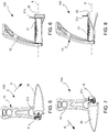
- Such first elastic means 28 have an extension direction parallel to the main axis X of the base element 20 to allow the bending of the second semi-arch element 30 along such a main axis X away from the first semi-arch element 10 as shown in figure 4 .
- Such a bending is effected, for example, as a result of the application of a force by the rider's foot on the second semi-arch element 30 towards the outside of the stirrup 100.
- Such a second semi-arch element elastically returns to a rest position as a result of the ceasing of such a force.
- the first elastic means comprise an extension coil spring 28 housed in a compartment 29 provided in the base element 20.
- Such an extension coil spring 28 has a coupling portion 28a attached to the end 5 of the second semi-arch element 30 and an opposite tapered portion 28b configured to engage with first adjustment means 40, 41 rotatable for changing a length L of such an extension spring 28.
- the compartment 29 provided in the base element 20 has a first length greater than the length L of the extension spring 28. Furthermore, referring to figure 2 , the coupling portion 28a of the spring 28 is connected to a bolt element 42 accommodated in a transverse through hole 5' provided in the end 5 of the second semi-arch element 30.
- the aforesaid first rotatable adjustment means comprise a threaded adjustment pin 40 coaxial to the extension spring 28 and insertable into such a tapered portion 28b of the extension spring.
- a threaded adjustment pin 40 coaxial to the extension spring 28 and insertable into such a tapered portion 28b of the extension spring.
- such an adjustment pin 40 includes an outer pin portion 40' to the extension spring 28 and an internal pin portion 40" to the extension spring.
- the first adjustment means further comprise, a respective nut 41 screwed on the adjustment pin portion 40" internal to the extension spring 28 and configured to abut against the tapered portion 28b of the extension spring itself to oppose a free sliding of such a tapered portion 28b towards the opposite coupling portion 28a of the spring 28 at the end 5 of the second semi-arch element 30.
- the extension spring 28 parallel to base element 20 allows to bend the second semi-arch element or safety arch 30 along the direction of the axis X, ensuring that the same elastically returns to the initial position at the end of the movement.
- the yielding of the second semi-arch element 30 may be calibrated on the weight of the rider by acting on the extension spring 28.
- a calibration is obtainable, for example, in two equivalent manners.
- a first manner provides for acting directly from the outside of the stirrup 100, intervening on the head of the threaded adjustment pin 40 of the extension spring 28, for example by screwing or unscrewing such a pin.
- the head of the threaded pin 40 is accessed by removing a cover element 55 attached to the base element 20 with screws 56.
- a second manner provides for removing the platform 21 of the stirrup 100, by unscrewing the respective screws 58, to replace the extension spring 28.
- the presence of the rib 21c of the platform 21, engaged in the recess 75 of the second semi-arch element 30 in a rest or normal use position of the stirrup gives greater rigidity and inertia to such a semi-arch element 30 and defines a rider's foot support surface separate from the second bendable semi-arch element.
- the rib 21c allows to prevent undesired bendings of the second semi-arch element 30 along the direction of the axis X during the normal performance of the horseback riding activity and ensures greater comfort in the support of the rider's foot on the platform 21.
- the second semi-arch element 30, released from the rib 21c of the platform 21, is rotatable about the direction of the axis X both clockwise (direction indicated by the first arrow A) and counter clockwise (direction indicated by the second arrow B).
- the second semi-arch element 30 is rotatable both in the direction indicated by the first arrow A and in that indicated by the second one B, to take a plurality of intermediate positions between the normal use position of the stirrup 100 and respective first and second end stop positions.
- Such first and second end stop positions are placed at angles of ⁇ 90° from such a normal use position (corresponding to an angle of 0°). In other words, such first and second end stop positions are opposed each other and placed at angles of 90° from such a rest position.
- the rotation of the second semi-arch element 30 in the direction of the arrows A and B may be caused, for example, by the rider's foot movement when falling.
- the safety stirrup 100 of the invention is configured to allow an eased disengagement of the rider's foot in the event of falling as compared to the known stirrups.
- the opposite rotation of the second semi-arch element 30 from the end stop positions or one of the intermediate positions mentioned above towards the normal use position of the stirrup 100 may be performed manually.
- the second semi-arch element 30 of the stirrup 100 comprises a shell or cover 57, for example snap attached, in a removable manner, to the second semi-arch element 30.
- a cover 57 allows the rider to aesthetically customize the safety arch 30 of the stirrup 100 by choosing both the material and the pattern of the cover 57.
- the shell 57 is, for example, manufactured in a material selected from the group consisting of:
- an advantage offered by the removable attachment of the shell or cover 57 to the stirrup is the ability to replace the damaged or otherwise worn shells with new shells in order to restore the original aesthetic appearance of the stirrup or to modify it and embellish it.
- the first semi-arch element 10 has an inclination with respect to a plane parallel to the base element 20 of the stirrup 100 of between 40° and 50°, preferably an inclination of 45°.
- Such an inclination offers the advantage, once mounted on a horse, of allowing to ease the retrieval of the stirrup in the event of involuntary disengagement of the foot from the stirrup itself.
- the first semi-arch element 10 of the stirrup of the invention 100 comprises a first through hole 50 for inserting a bent portion of the stirrup leather.
- a bent portion of the stirrup leather may slide in the first through hole 50 to reduce a distance of the stirrup 100 from the saddle from an initial use condition to a second use condition of the stirrup.
- the stirrup 100 is placed in the high position of the stirrup leather corresponding to a work position without rider.
- the rider may quickly return the stirrup to the initial use condition, i.e. in the low position of the stirrup leather, corresponding to a work position with rider, by simply pulling the stirrup 100 until disengaging the bent portion of the stirrup leather from the first through hole 50.
- such a stirrup comprises further first elastic means interposed between the end of the second semi-arch element and the second portion of the base element, in which such first elastic means have an extension direction orthogonal to a plane parallel to the base element.
- first elastic means which become effective in a respective extension coil spring, allow the bending of the second semi-arch element both along the direction of the main extension axis X of the base element and along the directions Y, Z orthogonal to the aforesaid main direction away from the first semi-arch element.
- the stirrup 100 comprises the second bendable semi-arch element 30 associated with the extension spring 28 parallel to the base element 20 and all the structural and functional features connected thereto as described above, including the rib 21c of the platform 21 housable in the recess 75.
- Such a stirrup comprises neither the elastic means 22 interposed between the platform 21 and the base element 20, nor the removable friction elements 25 associated with the platform 21 itself.
- the stirrup 100 only comprises the elastic means 22 interposed between the platform 21 and the base element 20 with respective adjustment means 23, 24 and with all the structural and functional features of the stirrup connected thereto and described above.
- the stirrup comprises neither the removable friction elements 25 associated with the platform 21 nor the second bendable semi-arch element 30.
- the second semi-arch element 30 comprises the end 5 integrally connected to the second portion 6 of the base element 20.
- the stirrup 100 only comprises the removable friction elements 25 associated with the platform 21 and with all the structural and functional features of the stirrup connected thereto and described above.
- the stirrup comprises neither elastic means 22, interposed between the platform 21 and the base element 20, nor the second bendable semi-arch element 30.
- the safety stirrup 100 for horseback riding of the present invention has many advantages and achieves the intended objects.
- stirrup 100 allows the rider to calibrate the force with which the semi-arch-safety arch 30 is bent.
- Such a property together with the possibility offered by the second semi-arch element 30 to rotate about the main axis X, for example as a result of the abrupt movement of the rider's foot when falling, allows an easier disengagement of the rider's foot in the event of falling than the known stirrups, and achieves an undoubted improvement in terms of safety of the stirrup of the invention.
- the extension spring 28 may be calibrated according to the weight of the rider (for example, a child, a woman and a man).
- stirrup 100 allows to adjust the pressure level exertable by the rider's foot on the platform 21, i.e. the cushioned platform may be calibrated on the weight of the rider to reduce the impact stress on the rider's joints during the performance of the sporting activity.
- the stirrup 100 increases the comfort of the rider during the performance of the horseback riding activity.
- stirrup 100 of the invention improves the safety degree offered by increasing the grip or adherence of the rider's sporting footwear to the platform 21 so as to adapt it to the physical and sporting needs of different riders.
Landscapes
- Engineering & Computer Science (AREA)
- Mechanical Engineering (AREA)
- Professional, Industrial, Or Sporting Protective Garments (AREA)
- Footwear And Its Accessory, Manufacturing Method And Apparatuses (AREA)
- Credit Cards Or The Like (AREA)
- Exposure Control For Cameras (AREA)
Priority Applications (1)
| Application Number | Priority Date | Filing Date | Title |
|---|---|---|---|
| EP17203887.9A EP3305718B1 (fr) | 2016-05-27 | 2017-05-25 | Étrier de sécurité d'équitation |
Applications Claiming Priority (1)
| Application Number | Priority Date | Filing Date | Title |
|---|---|---|---|
| ITUA2016A003878A ITUA20163878A1 (it) | 2016-05-27 | 2016-05-27 | Staffa per discipline equestri perfezionata |
Related Child Applications (1)
| Application Number | Title | Priority Date | Filing Date |
|---|---|---|---|
| EP17203887.9A Division EP3305718B1 (fr) | 2016-05-27 | 2017-05-25 | Étrier de sécurité d'équitation |
Publications (1)
| Publication Number | Publication Date |
|---|---|
| EP3248935A1 true EP3248935A1 (fr) | 2017-11-29 |
Family
ID=56990848
Family Applications (3)
| Application Number | Title | Priority Date | Filing Date |
|---|---|---|---|
| EP17172939.5A Active EP3248934B1 (fr) | 2016-05-27 | 2017-05-25 | Étrier de sécurité d'équitation |
| EP17172941.1A Withdrawn EP3248935A1 (fr) | 2016-05-27 | 2017-05-25 | Étrier amélioré pour disciplines d'équitation |
| EP17203887.9A Active EP3305718B1 (fr) | 2016-05-27 | 2017-05-25 | Étrier de sécurité d'équitation |
Family Applications Before (1)
| Application Number | Title | Priority Date | Filing Date |
|---|---|---|---|
| EP17172939.5A Active EP3248934B1 (fr) | 2016-05-27 | 2017-05-25 | Étrier de sécurité d'équitation |
Family Applications After (1)
| Application Number | Title | Priority Date | Filing Date |
|---|---|---|---|
| EP17203887.9A Active EP3305718B1 (fr) | 2016-05-27 | 2017-05-25 | Étrier de sécurité d'équitation |
Country Status (3)
| Country | Link |
|---|---|
| US (2) | US10457542B2 (fr) |
| EP (3) | EP3248934B1 (fr) |
| IT (1) | ITUA20163878A1 (fr) |
Cited By (3)
| Publication number | Priority date | Publication date | Assignee | Title |
|---|---|---|---|---|
| EP3521240A1 (fr) * | 2018-02-02 | 2019-08-07 | Philippe Maloigne | Étrier de sécurité pour l'équitation |
| US11365114B2 (en) | 2017-09-29 | 2022-06-21 | Philippe Maloigne | Stirrup with opening and closing function |
| IT202100016949A1 (it) * | 2021-06-29 | 2022-12-29 | Stefano Gajo | “migliorata staffa da equitazione” |
Families Citing this family (2)
| Publication number | Priority date | Publication date | Assignee | Title |
|---|---|---|---|---|
| US20170275151A1 (en) * | 2016-03-22 | 2017-09-28 | Shano Group, LLC | Ridding stirrups with detachable foot beds |
| US12060260B2 (en) * | 2022-12-21 | 2024-08-13 | Jone Shou Industrial Co., Ltd. | Stirrup having deformable and detachable structure |
Citations (4)
| Publication number | Priority date | Publication date | Assignee | Title |
|---|---|---|---|---|
| US3157977A (en) * | 1962-08-20 | 1964-11-24 | Jr John D Kitchingham | Safety stirrup |
| AU8251575A (en) * | 1974-06-28 | 1977-01-06 | Cornish A T | Improvements to horse riding stirrups |
| US20110146214A1 (en) * | 2009-12-17 | 2011-06-23 | Isidore Strauss | Stirrup pad |
| FR2964961A1 (fr) * | 2010-09-21 | 2012-03-23 | Philippe Catin | Etrier d'equitation et systeme d'equitation correspondant |
Family Cites Families (23)
| Publication number | Priority date | Publication date | Assignee | Title |
|---|---|---|---|---|
| US475127A (en) * | 1892-05-17 | Nixre | ||
| DE3317859A1 (de) * | 1983-05-17 | 1984-11-22 | Erwin 5000 Köln Meroth | Sicherheitssteigbuegel mit einem u-foermigen oberteil und einem gelenkig mit diesem verbundenen unterteil |
| US4969316A (en) * | 1989-02-14 | 1990-11-13 | Brown Roy L | Safety stirrup |
| US5794419A (en) * | 1996-03-22 | 1998-08-18 | Cohen; Martin D. | Equestrian stirrup iron |
| US6220004B1 (en) * | 1998-08-28 | 2001-04-24 | Eastwest International (Taiwan) Enterprises | Swiveled-eye safety stirrup with shock-absorbed hinged footrest |
| US6282872B1 (en) * | 2000-01-21 | 2001-09-04 | Frank Schulte | Safety mounting assist stirrup |
| DE10043878C2 (de) * | 2000-09-04 | 2003-04-30 | Dms Der Moderne Sportbedarf Gm | Steigbügel mit federnder Trittplatte |
| US6629405B2 (en) * | 2001-09-14 | 2003-10-07 | Johnny E. Johnson | Western style stirrup with internal springs |
| US7065943B2 (en) * | 2002-01-25 | 2006-06-27 | Eastwest International (Taiwan) Enterprises | Stirrup with footrest having a gas filled shock absorber |
| US7328562B2 (en) * | 2002-01-25 | 2008-02-12 | Chia Wei Chang | Stirrup with gas-filled shock absorber |
| US6766632B2 (en) * | 2002-01-25 | 2004-07-27 | Eastwest International (Taiwan) Enterprises | Stirrup with relatively movable footrest and hanger |
| US7114315B2 (en) * | 2002-01-25 | 2006-10-03 | Eastwest International (Taiwan) Enterprises | Nonslip article for a stirrup |
| US20030140605A1 (en) * | 2002-01-25 | 2003-07-31 | Chang Hsi-Chang | Stirrup with clamped shock-absorbing pads |
| FR2836469B1 (fr) * | 2002-02-22 | 2004-08-20 | Dubourg Yann Frederic | Etrier d'equitation a fixation automatique |
| US6898924B1 (en) * | 2003-11-26 | 2005-05-31 | Mccoy Michael J. | Safety release attachment for stirrup |
| FR2873674A1 (fr) * | 2004-08-02 | 2006-02-03 | Rainfray Yves | Etrier de securite |
| FR2880340A1 (fr) * | 2005-01-04 | 2006-07-07 | Michel Claude Perrot | Etrier a deux planchers dont l'un est escamotable automatiquement |
| FR2881127B1 (fr) * | 2005-01-24 | 2007-05-04 | Guy Morin | Etrier d'equitation 3d a assistance de pied amortissant, ergonomique, antiblocage, adaptable au poids du cavalier |
| US8413411B2 (en) * | 2007-04-26 | 2013-04-09 | Robert Gottlieb | Horse mounting stirrup |
| FR2946331B1 (fr) * | 2009-06-04 | 2012-08-03 | Freejumpsystem | Etrier d'equitation de securite |
| WO2014095400A1 (fr) * | 2012-12-21 | 2014-06-26 | Herm. Sprenger Gmbh & Co. Kg | Semelle d'étrier et étrier muni d'un plancher et d'une semelle d'étrier |
| US9840408B2 (en) * | 2015-01-02 | 2017-12-12 | Louise A. Ford | Retractable stirrup extension |
| GB2544963A (en) * | 2015-11-11 | 2017-06-07 | Arnett John | Stirrup |
-
2016
- 2016-05-27 IT ITUA2016A003878A patent/ITUA20163878A1/it unknown
-
2017
- 2017-05-25 EP EP17172939.5A patent/EP3248934B1/fr active Active
- 2017-05-25 EP EP17172941.1A patent/EP3248935A1/fr not_active Withdrawn
- 2017-05-25 EP EP17203887.9A patent/EP3305718B1/fr active Active
- 2017-05-28 US US15/607,503 patent/US10457542B2/en active Active
- 2017-05-29 US US15/607,631 patent/US10717640B2/en active Active
Patent Citations (4)
| Publication number | Priority date | Publication date | Assignee | Title |
|---|---|---|---|---|
| US3157977A (en) * | 1962-08-20 | 1964-11-24 | Jr John D Kitchingham | Safety stirrup |
| AU8251575A (en) * | 1974-06-28 | 1977-01-06 | Cornish A T | Improvements to horse riding stirrups |
| US20110146214A1 (en) * | 2009-12-17 | 2011-06-23 | Isidore Strauss | Stirrup pad |
| FR2964961A1 (fr) * | 2010-09-21 | 2012-03-23 | Philippe Catin | Etrier d'equitation et systeme d'equitation correspondant |
Cited By (5)
| Publication number | Priority date | Publication date | Assignee | Title |
|---|---|---|---|---|
| US11365114B2 (en) | 2017-09-29 | 2022-06-21 | Philippe Maloigne | Stirrup with opening and closing function |
| EP3521240A1 (fr) * | 2018-02-02 | 2019-08-07 | Philippe Maloigne | Étrier de sécurité pour l'équitation |
| FR3077565A1 (fr) * | 2018-02-02 | 2019-08-09 | Philippe Maloigne | Etrier de securite pour l'equitation |
| US11142450B2 (en) | 2018-02-02 | 2021-10-12 | Philippe Maloigne | Stirrup for horse-riding |
| IT202100016949A1 (it) * | 2021-06-29 | 2022-12-29 | Stefano Gajo | “migliorata staffa da equitazione” |
Also Published As
| Publication number | Publication date |
|---|---|
| US20180002157A1 (en) | 2018-01-04 |
| EP3305718A1 (fr) | 2018-04-11 |
| ITUA20163878A1 (it) | 2017-11-27 |
| US10717640B2 (en) | 2020-07-21 |
| EP3305718B1 (fr) | 2020-03-18 |
| US10457542B2 (en) | 2019-10-29 |
| EP3248934A1 (fr) | 2017-11-29 |
| US20170341925A1 (en) | 2017-11-30 |
| EP3248934B1 (fr) | 2020-04-01 |
Similar Documents
| Publication | Publication Date | Title |
|---|---|---|
| EP3248934B1 (fr) | Étrier de sécurité d'équitation | |
| EP0328376A1 (fr) | Plaque de pommeau et arçon pour selle | |
| US10139187B2 (en) | Crossbow with attachment for protecting broadhead of arrow | |
| US5343674A (en) | Racing saddle | |
| US7874131B2 (en) | Three-dimensional, shock-absorbing, ergonomic, anti-blocking ridings stirrup that can be adapted to the weight of the rider and comprises a foot assisting mechanism | |
| US7024962B2 (en) | Bicycle pedal assembly having a pedal body that is formed with an integral front cleat-retaining member | |
| JP6888182B2 (ja) | クリップレス自転車ペダルのクリートアセンブリ | |
| EP1514837A1 (fr) | Etrier de sécurité avec partie élastique et amovible | |
| US20230380535A1 (en) | Helmet harness and coupler | |
| EP3972894B1 (fr) | Unité d'adaptateur de frein arrière de motocyclette | |
| EP4279443A1 (fr) | Arçon de selle pour une selle d'équitation | |
| US20200377171A1 (en) | Automatic Cycle Pedal | |
| US10315096B2 (en) | Ice skate blade arrangement | |
| US20180326293A1 (en) | Inline skate having adjustable shock absorber | |
| EP1018904A1 (fr) | Ameliorations apportees aux eperons | |
| EP2670699A1 (fr) | Étrier d'équitation | |
| EP2440445B1 (fr) | Guidon de bicyclette | |
| CN108479049B (zh) | 一种直排轮溜冰鞋 | |
| EP1359116A1 (fr) | Selle d'équitation | |
| JP3213177U (ja) | スノーボード用ベースプレート | |
| IL269141B2 (en) | Grip extender for a firearm | |
| CN101218000A (zh) | 安全头盔及其呼吸面具悬挂机构 | |
| JP2021137080A (ja) | スノーボードのバインディングの取付構造 | |
| NO315700B1 (no) | Sal | |
| DE102014011312A1 (de) | Fersenhaken |
Legal Events
| Date | Code | Title | Description |
|---|---|---|---|
| PUAI | Public reference made under article 153(3) epc to a published international application that has entered the european phase |
Free format text: ORIGINAL CODE: 0009012 |
|
| AK | Designated contracting states |
Kind code of ref document: A1 Designated state(s): AL AT BE BG CH CY CZ DE DK EE ES FI FR GB GR HR HU IE IS IT LI LT LU LV MC MK MT NL NO PL PT RO RS SE SI SK SM TR |
|
| AX | Request for extension of the european patent |
Extension state: BA ME |
|
| STAA | Information on the status of an ep patent application or granted ep patent |
Free format text: STATUS: THE APPLICATION IS DEEMED TO BE WITHDRAWN |
|
| 18D | Application deemed to be withdrawn |
Effective date: 20180530 |