EP3249207A2 - Eingangslufterwärmungssystem für ein fahrzeug - Google Patents
Eingangslufterwärmungssystem für ein fahrzeug Download PDFInfo
- Publication number
- EP3249207A2 EP3249207A2 EP17172992.4A EP17172992A EP3249207A2 EP 3249207 A2 EP3249207 A2 EP 3249207A2 EP 17172992 A EP17172992 A EP 17172992A EP 3249207 A2 EP3249207 A2 EP 3249207A2
- Authority
- EP
- European Patent Office
- Prior art keywords
- resistance
- heater coil
- switching device
- electrical switching
- control circuit
- Prior art date
- Legal status (The legal status is an assumption and is not a legal conclusion. Google has not performed a legal analysis and makes no representation as to the accuracy of the status listed.)
- Granted
Links
Images




Classifications
-
- F—MECHANICAL ENGINEERING; LIGHTING; HEATING; WEAPONS; BLASTING
- F02—COMBUSTION ENGINES; HOT-GAS OR COMBUSTION-PRODUCT ENGINE PLANTS
- F02M—SUPPLYING COMBUSTION ENGINES IN GENERAL WITH COMBUSTIBLE MIXTURES OR CONSTITUENTS THEREOF
- F02M31/00—Apparatus for thermally treating combustion-air, fuel, or fuel-air mixture
- F02M31/02—Apparatus for thermally treating combustion-air, fuel, or fuel-air mixture for heating
- F02M31/12—Apparatus for thermally treating combustion-air, fuel, or fuel-air mixture for heating electrically
- F02M31/13—Combustion air
-
- F—MECHANICAL ENGINEERING; LIGHTING; HEATING; WEAPONS; BLASTING
- F02—COMBUSTION ENGINES; HOT-GAS OR COMBUSTION-PRODUCT ENGINE PLANTS
- F02M—SUPPLYING COMBUSTION ENGINES IN GENERAL WITH COMBUSTIBLE MIXTURES OR CONSTITUENTS THEREOF
- F02M35/00—Combustion-air cleaners, air intakes, intake silencers, or induction systems specially adapted for, or arranged on, internal-combustion engines
- F02M35/10—Air intakes; Induction systems
- F02M35/10242—Devices or means connected to or integrated into air intakes; Air intakes combined with other engine or vehicle parts
- F02M35/10249—Electrical or electronic devices fixed to the intake system; Electric wiring
-
- F—MECHANICAL ENGINEERING; LIGHTING; HEATING; WEAPONS; BLASTING
- F02—COMBUSTION ENGINES; HOT-GAS OR COMBUSTION-PRODUCT ENGINE PLANTS
- F02M—SUPPLYING COMBUSTION ENGINES IN GENERAL WITH COMBUSTIBLE MIXTURES OR CONSTITUENTS THEREOF
- F02M35/00—Combustion-air cleaners, air intakes, intake silencers, or induction systems specially adapted for, or arranged on, internal-combustion engines
- F02M35/10—Air intakes; Induction systems
- F02M35/10242—Devices or means connected to or integrated into air intakes; Air intakes combined with other engine or vehicle parts
- F02M35/10268—Heating, cooling or thermal insulating means
-
- F—MECHANICAL ENGINEERING; LIGHTING; HEATING; WEAPONS; BLASTING
- F02—COMBUSTION ENGINES; HOT-GAS OR COMBUSTION-PRODUCT ENGINE PLANTS
- F02N—STARTING OF COMBUSTION ENGINES; STARTING AIDS FOR SUCH ENGINES, NOT OTHERWISE PROVIDED FOR
- F02N19/00—Starting aids for combustion engines, not otherwise provided for
- F02N19/02—Aiding engine start by thermal means, e.g. using lighted wicks
- F02N19/04—Aiding engine start by thermal means, e.g. using lighted wicks by heating of fluids used in engines
-
- H—ELECTRICITY
- H05—ELECTRIC TECHNIQUES NOT OTHERWISE PROVIDED FOR
- H05B—ELECTRIC HEATING; ELECTRIC LIGHT SOURCES NOT OTHERWISE PROVIDED FOR; CIRCUIT ARRANGEMENTS FOR ELECTRIC LIGHT SOURCES, IN GENERAL
- H05B1/00—Details of electric heating devices
- H05B1/02—Automatic switching arrangements specially adapted to apparatus ; Control of heating devices
- H05B1/0202—Switches
-
- H—ELECTRICITY
- H05—ELECTRIC TECHNIQUES NOT OTHERWISE PROVIDED FOR
- H05B—ELECTRIC HEATING; ELECTRIC LIGHT SOURCES NOT OTHERWISE PROVIDED FOR; CIRCUIT ARRANGEMENTS FOR ELECTRIC LIGHT SOURCES, IN GENERAL
- H05B3/00—Ohmic-resistance heating
- H05B3/0014—Devices wherein the heating current flows through particular resistances
-
- F—MECHANICAL ENGINEERING; LIGHTING; HEATING; WEAPONS; BLASTING
- F02—COMBUSTION ENGINES; HOT-GAS OR COMBUSTION-PRODUCT ENGINE PLANTS
- F02D—CONTROLLING COMBUSTION ENGINES
- F02D41/00—Electrical control of supply of combustible mixture or its constituents
- F02D41/20—Output circuits, e.g. for controlling currents in command coils
- F02D2041/202—Output circuits, e.g. for controlling currents in command coils characterised by the control of the circuit
- F02D2041/2024—Output circuits, e.g. for controlling currents in command coils characterised by the control of the circuit the control switching a load after time-on and time-off pulses
- F02D2041/2027—Control of the current by pulse width modulation or duty cycle control
-
- F—MECHANICAL ENGINEERING; LIGHTING; HEATING; WEAPONS; BLASTING
- F02—COMBUSTION ENGINES; HOT-GAS OR COMBUSTION-PRODUCT ENGINE PLANTS
- F02D—CONTROLLING COMBUSTION ENGINES
- F02D41/00—Electrical control of supply of combustible mixture or its constituents
- F02D41/24—Electrical control of supply of combustible mixture or its constituents characterised by the use of digital means
- F02D41/26—Electrical control of supply of combustible mixture or its constituents characterised by the use of digital means using computer, e.g. microprocessor
- F02D41/266—Electrical control of supply of combustible mixture or its constituents characterised by the use of digital means using computer, e.g. microprocessor the computer being backed-up or assisted by another circuit, e.g. analogue
-
- Y—GENERAL TAGGING OF NEW TECHNOLOGICAL DEVELOPMENTS; GENERAL TAGGING OF CROSS-SECTIONAL TECHNOLOGIES SPANNING OVER SEVERAL SECTIONS OF THE IPC; TECHNICAL SUBJECTS COVERED BY FORMER USPC CROSS-REFERENCE ART COLLECTIONS [XRACs] AND DIGESTS
- Y02—TECHNOLOGIES OR APPLICATIONS FOR MITIGATION OR ADAPTATION AGAINST CLIMATE CHANGE
- Y02T—CLIMATE CHANGE MITIGATION TECHNOLOGIES RELATED TO TRANSPORTATION
- Y02T10/00—Road transport of goods or passengers
- Y02T10/10—Internal combustion engine [ICE] based vehicles
- Y02T10/12—Improving ICE efficiencies
Definitions
- Heating the intake air may allow for easier ignition and may hold the fuel in suspension more effectively, leading to fewer fuel droplets falling out of suspension in the air.
- Intake air heating systems may allow for faster starts of the engine, may reduce startup emissions (sometimes evidenced as "white smoke"), reduce engine wear, reduce overall battery consumption during startup, and reduce startup fuel consumption.
- control circuit is configured to perform closed-loop control of the temperature of the heater coil to the desired temperature value by controlling the measured resistance of the heater coil to a target resistance corresponding to the desired temperature value.
- control circuit is configured to measure the resistance of the heater coil by measuring a current value of current through the electrical switching device and a voltage value at a terminal of the electrical switching device and calculating the resistance of the heater coil based on a ratio of the measured voltage value to the measured current value.
- control circuit is configured to measure a reference voltage at the terminal of the electrical switching device while the electrical switching device is off and subtract the reference voltage from the measured voltage value prior to calculating the resistance of the heater coil.
- electrical switching device comprises a plurality of transistors connected in parallel.
- control circuit is configured to drive the electrical switching device using pulse-width modulation.
- the system includes a temperature sensor configured to measure a temperature of at least one of the control circuit and the electrical switching device.
- the control circuit is configured to turn off the electrical switching device in response to the measured temperature exceeding a temperature threshold.
- the system includes a metal enclosure housing the electrical switching device and the control circuit. The electrical switching device is thermally coupled to the metal enclosure, which absorbs heat from the electrical switching device.
- the method includes estimating a connection resistance. Estimating the connection resistance includes determining a rate of resistance rise of the heater coil over a period of interest and determining an initial resistance offset based on the rate of resistance rise. Estimating the connection resistance further includes scaling the rate of resistance rise by a ratio of (i) a reference current squared value to (ii) cumulative current squared during a present actuation of the heater coil and subtracting the initial resistance offset and a predetermined reference resistance of the heater coil from a value of the measured resistance. The value of the measured resistance is measured within one second of initial actuation of the heater coil. The method includes subtracting connection resistance from the measured resistance prior to comparing the measured resistance to a target resistance corresponding to the desired temperature value.
- connection resistance may be ignored. That may not be an accurate assumption and so connection resistance is determined and factored out.
- a first approach might be to simply measure the temperature of the air heater (without supplying power to the air heater), and calculating that the difference between the measured resistance and the known air heater resistance is the connection resistance.
- the air heater may not actually be at the ambient temperature. This will likely be true in a warm or hot start situation, where the engine has not "soaked” in the ambient temperature for a long enough period that all the engine components have returned to the ambient temperature. If the engine components have returned to the ambient temperature, such as when a vehicle is sitting overnight, this is referred to as a cold start. Without knowing the temperature of the air heater, the air heater controller cannot infer the resistance of the air heater in order to calculate the connection resistance.
- the reference can be subtracted from the voltage at the positive side of the air heater when current is being supplied to the air heater.
- This reference (referred to as heater ground) voltage measurement can be performed as frequently as needed based on expected fluctuations in the heater ground. For example, if fluctuations of interest in the heater ground take place over the course of seconds rather than milliseconds, the heater ground measurement may be performed once per second.
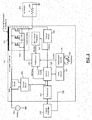
- the battery 220 provides power to the starter 224, to the engine controller 216, and to the air heater controller 204, which selectively connects that power to the air heater 208.
- the solid lines show the ground connections of the battery to a frame 228 of the truck 200 as well as to the engine controller 216.
- the engine 212 is grounded to the frame 228. This is simply one grounding configuration shown for example, and the principles of the present disclosure are not limited to this configuration.
- a temperature cut-off 336 supplies a disable signal to the PWM driver 316 in response to a temperature of the air heater controller 204 increasing above a threshold.
- a thermistor 340 may measure a temperature of an enclosure of the air heater controller 204, a package of one or more of the power switches 300, etc.
- the resistance of the element in the air heater 208 is shown schematically as a resistor 348.
- the battery 220 may be characterized by an internal resistance (not shown), which may be one indication of the health of the battery 220.
- the control circuit 328 may measure a first voltage of the battery 220 with the power switches 300 off. For example, the control circuit 328 may receive a voltage value of one of the terminals of the shunt resistor 304 measured by the current monitor 308. The control circuit 328 can then turn on the power switches 300 and measure a second voltage of the battery 220 and the current through the shunt resistor 304. The internal resistance of the battery can then be calculated by the control circuit 328 as the difference between the first and second voltages divided by the current.
- control is now able to determine the connection resistance present in series with the air heater by subtracting the heater resistance at the reference temperature (such as 20 °C) and the thermal resistance offset from the resistance measured at startup.
- the measured resistance at startup may be taken not at the very first reading, but instead at some small amount of time later (such as 250 milliseconds) to avoid errors caused by startup transients. For example, the small amount of time may mean less than one second.
- code may include software, firmware, and/or microcode, and may refer to programs, routines, functions, classes, data structures, and/or objects.
- shared processor circuit encompasses a single processor circuit that executes some or all code from multiple modules.
- group processor circuit encompasses a processor circuit that, in combination with additional processor circuits, executes some or all code from one or more modules. References to multiple processor circuits encompass multiple processor circuits on discrete dies, multiple processor circuits on a single die, multiple cores of a single processor circuit, multiple threads of a single processor circuit, or a combination of the above.
- shared memory circuit encompasses a single memory circuit that stores some or all code from multiple modules.
- group memory circuit encompasses a memory circuit that, in combination with additional memories, stores some or all code from one or more modules.
Landscapes
- Engineering & Computer Science (AREA)
- Chemical & Material Sciences (AREA)
- Combustion & Propulsion (AREA)
- Mechanical Engineering (AREA)
- General Engineering & Computer Science (AREA)
- Combined Controls Of Internal Combustion Engines (AREA)
- Air-Conditioning For Vehicles (AREA)
- Control Of Resistance Heating (AREA)
Applications Claiming Priority (1)
| Application Number | Priority Date | Filing Date | Title |
|---|---|---|---|
| US15/166,009 US10077745B2 (en) | 2016-05-26 | 2016-05-26 | Intake air heating system for a vehicle |
Publications (3)
| Publication Number | Publication Date |
|---|---|
| EP3249207A2 true EP3249207A2 (de) | 2017-11-29 |
| EP3249207A3 EP3249207A3 (de) | 2018-03-21 |
| EP3249207B1 EP3249207B1 (de) | 2021-08-04 |
Family
ID=58800692
Family Applications (1)
| Application Number | Title | Priority Date | Filing Date |
|---|---|---|---|
| EP17172992.4A Active EP3249207B1 (de) | 2016-05-26 | 2017-05-26 | Eingangslufterwärmungssystem für ein fahrzeug |
Country Status (4)
| Country | Link |
|---|---|
| US (1) | US10077745B2 (de) |
| EP (1) | EP3249207B1 (de) |
| CN (1) | CN107435602B (de) |
| DK (1) | DK3249207T3 (de) |
Cited By (3)
| Publication number | Priority date | Publication date | Assignee | Title |
|---|---|---|---|---|
| WO2023072763A1 (fr) * | 2021-10-28 | 2023-05-04 | Valeo Equipements Electriques Moteur | Dispositif de détermination de la position angulaire d'un rotor de machine électrique tournante |
| US11649790B1 (en) * | 2022-03-21 | 2023-05-16 | Weichai Power Co., Ltd. | Control method and apparatus applied to controller |
| EP4357604A1 (de) * | 2022-10-17 | 2024-04-24 | Phillips & Temro Industries Inc. | Ansauglufterwärmungssysteme und -verfahren |
Families Citing this family (3)
| Publication number | Priority date | Publication date | Assignee | Title |
|---|---|---|---|---|
| US11716788B2 (en) * | 2020-02-18 | 2023-08-01 | Gentherm Gmbh | Heater control system based on slope of supply current |
| WO2022242894A1 (en) * | 2021-05-16 | 2022-11-24 | Eaton Intelligent Power Limited | Aftertreatment heater power electronics |
| US12442352B1 (en) * | 2024-06-26 | 2025-10-14 | Saudi Arabian Oil Company | Systems and methods for coordinating an air blend valve with an intake air heater |
Citations (1)
| Publication number | Priority date | Publication date | Assignee | Title |
|---|---|---|---|---|
| US7472695B2 (en) | 2003-07-28 | 2009-01-06 | Phillips & Temro Industries Inc. | Controller for air intake heater |
Family Cites Families (55)
| Publication number | Priority date | Publication date | Assignee | Title |
|---|---|---|---|---|
| US3851278A (en) | 1972-06-12 | 1974-11-26 | Bell & Howell Japan | Inverter circuit |
| JPS49120023A (de) | 1973-03-28 | 1974-11-16 | ||
| CA1008499A (en) | 1974-06-28 | 1977-04-12 | James B. Carter Limited | Interior car warmer |
| JPS60247030A (ja) * | 1984-05-22 | 1985-12-06 | Nippon Denso Co Ltd | エンジンの制御装置 |
| JPS61715A (ja) * | 1984-06-13 | 1986-01-06 | Nippon Denso Co Ltd | 熱式空気流量検出装置 |
| EP0206215B1 (de) * | 1985-06-18 | 1988-12-07 | Nippondenso Co., Ltd. | Hitzdraht-Luftströmungsmessgerät |
| US4944260A (en) | 1989-06-05 | 1990-07-31 | Cummins Electronics, Inc. | Air intake heater system for internal combustion engines |
| US5094198A (en) | 1991-04-26 | 1992-03-10 | Cummins Electronics Company, Inc. | Air intake heating method and device for internal combustion engines |
| JP2682348B2 (ja) * | 1992-09-17 | 1997-11-26 | 株式会社日立製作所 | 空気流量計及び空気流量検出方法 |
| US5347966A (en) | 1993-06-25 | 1994-09-20 | Cummins Engine Company, Inc. | Speed-dependent air intake system and method for internal combustion engines |
| IE950365A1 (en) | 1994-09-27 | 1996-04-03 | Armstrong Charles V | Power cut-off device |
| US5666254A (en) | 1995-09-14 | 1997-09-09 | Raychem Corporation | Voltage sensing overcurrent protection circuit |
| US5990459A (en) | 1996-10-15 | 1999-11-23 | David + Baader - DBK | System for controlling a plurality of resistive heating elements |
| US5922232A (en) | 1997-02-26 | 1999-07-13 | Beru Ag | Self-regulating heating element |
| US6118239A (en) | 1998-11-23 | 2000-09-12 | Kadah; Andrew S. | Speed control drive circuit for blower motor |
| US6084218A (en) | 1999-05-25 | 2000-07-04 | Itt Manufacturing Enterprises, Inc. | Spa heater temperature control circuit |
| ES2187411T3 (es) | 2000-05-23 | 2003-06-16 | Catem Gmbh & Co Kg | Dispositivo calefactor electrico, especialmente para la aplicacion en automoviles. |
| DE10026339A1 (de) | 2000-05-26 | 2001-12-20 | Daimler Chrysler Ag | Vorrichtung zum Vorwärmen von Luft in einer zu einer Dieselbrennkraftmaschine führenden Ansaugleitung |
| DE10028073C2 (de) | 2000-06-07 | 2003-04-10 | Beru Ag | Verfahren und Schaltungsanordnung zum Aufheizen einer Glühkerze |
| DE10028446B4 (de) | 2000-06-14 | 2006-03-30 | Beru Ag | Elektrische Zusatzheizeinrichtung |
| US7259945B2 (en) | 2000-08-09 | 2007-08-21 | Server Technology, Inc. | Active arc-suppression circuit, system, and method of use |
| DE10041417A1 (de) | 2000-08-23 | 2002-03-21 | Beru Ag | Elektronische Ansteuerung für Heizelemente |
| US6606228B1 (en) | 2000-11-27 | 2003-08-12 | Ametek, Inc. | Fault detection circuit for use with a power control device |
| US6477047B1 (en) | 2000-11-30 | 2002-11-05 | Advanced Micro Devices, Inc. | Temperature sensor mounting for accurate measurement and durability |
| JP2002213309A (ja) | 2001-01-16 | 2002-07-31 | Hitachi Ltd | 加熱装置、エンジンの駆動方法とその装置並びに内燃機関用吸気モジュールとその部材 |
| US7016171B2 (en) | 2001-02-01 | 2006-03-21 | Hydro-Aire, Inc. | Current fault detector and circuit interrupter and packaging thereof |
| DE10105331A1 (de) | 2001-02-05 | 2002-08-29 | Beru Ag | Kaltstartanordnung für einen PKW-Dieselmotor |
| DE10135880A1 (de) | 2001-07-24 | 2003-02-13 | Beru Ag | Verfahren und Vorrichtung zum Steuern der Aufheizung der Glühkerzen eines Dieselmotors |
| US6696675B2 (en) | 2001-08-10 | 2004-02-24 | Tocco, Inc. | Induction heating system for internal combustion engine |
| DE10147074A1 (de) | 2001-09-25 | 2003-05-08 | Beru Ag | Verfahren zum Betreiben einer aus mehreren Heizelementen bestehenden mehrstufigen elektrischen Heizung |
| DE10147675A1 (de) | 2001-09-27 | 2003-04-30 | Beru Ag | Verfahren zum Aufheizen eines elektrischen Heizelementes, insbesondere einer Glühkerze für eine Brennkraftmaschine |
| DE10156037A1 (de) | 2001-11-15 | 2003-06-05 | Behr Hella Thermocontrol Gmbh | Verfahren zur Funktionsüberwachung eines elektrischen Heizelements einer Kfz-Zusatzheizung |
| US6870720B2 (en) | 2002-01-25 | 2005-03-22 | Pacific Engineering Corp. | Device and method for determining intermittent short circuit |
| DE10208103A1 (de) | 2002-02-26 | 2003-09-11 | Beru Ag | Elektrische Luftheizungsvorrichtung insbesondere für ein Kraftfahrzeug |
| DE10214166A1 (de) | 2002-03-28 | 2003-10-23 | David & Baader Gmbh | Heizflansch, insbesondere zum Vorwärmen von Luft in einer Ansaugleitung einer Brennkraftmaschine |
| US20040126286A1 (en) | 2002-06-19 | 2004-07-01 | Deruyter John C. | Method and apparatus for reducing a nitrogen oxide |
| AU2002368124A1 (en) * | 2002-07-24 | 2004-02-16 | Nagares, S.A. | System for controlling the intake air temperature in diesel internal combustion engines |
| DE10247042B3 (de) | 2002-10-09 | 2004-05-06 | Beru Ag | Verfahren und Vorrichtung zum Steuern der Aufheizung der Glühkerzen eines Dieselmotors |
| US20050092727A1 (en) | 2003-03-20 | 2005-05-05 | Fraley Peter D. | Independent electronics equipment heater using phase width modulation |
| US7190893B2 (en) | 2003-06-27 | 2007-03-13 | Valeo Electrical Systems, Inc. | Fluid heater with low porosity thermal mass |
| DE10332936A1 (de) | 2003-07-19 | 2005-02-10 | Daimlerchrysler Ag | Steuerung einer elektrisch beheizten Vorwärmeinrichtung für den Kaltstart von Verbrennungsmotoren |
| US7007460B2 (en) | 2003-08-11 | 2006-03-07 | General Motors Corporation | Apparatus and method for accelerated exhaust system component heating |
| EP1681457B2 (de) | 2003-10-08 | 2017-04-19 | Nagares, S.A. | Modul zur erwärmung der einlassgase eines kraftfahrzeugmotors mit integrierter elektronischer temperaturregelung |
| JP4359705B2 (ja) | 2003-12-08 | 2009-11-04 | 株式会社日立製作所 | 発熱抵抗式流量測定装置 |
| US20050257781A1 (en) | 2004-05-19 | 2005-11-24 | Linkenhoger Thomas E | Intake air pre-heated assembly for automotive gasoline engines |
| EP1852597B1 (de) | 2005-01-21 | 2008-08-06 | Nagares, S.A. | Modul zur erwärmung der einlassgase eines automobilmotors mit überhitzungsschutz und/oder geschlossenem regelkreis |
| US7957885B2 (en) | 2005-09-21 | 2011-06-07 | Kernwein Markus | Method for operating a group of glow plugs in a diesel engine |
| CA2524146C (en) * | 2005-11-18 | 2008-05-13 | Westport Research Inc. | Direct injection internal combustion engine and method of making and operating same |
| US8981264B2 (en) | 2006-02-17 | 2015-03-17 | Phillips & Temro Industries Inc. | Solid state switch |
| US8003922B2 (en) | 2006-02-17 | 2011-08-23 | Phillips & Temro Industries Inc. | Solid state switch with over-temperature and over-current protection |
| EP3179499B1 (de) | 2007-11-05 | 2018-01-17 | Phillips & Temro Industries Inc. | Steuerungssystem |
| US7873461B2 (en) | 2008-11-17 | 2011-01-18 | Gm Global Technology Operations, Inc. | Fuel temperature estimation in a spark ignited direct injection engine |
| JP5396144B2 (ja) * | 2009-05-14 | 2014-01-22 | 日本特殊陶業株式会社 | グロープラグの通電制御装置およびグロープラグ |
| DE102010051758B4 (de) | 2010-11-17 | 2020-03-19 | Andreas Stihl Ag & Co. Kg | Handgeführtes Arbeitsgerät mit einer Steuereinrichtung für ein elektrisches Heizelement |
| DE102012004526A1 (de) | 2012-03-06 | 2013-09-12 | Audi Ag | Verfahren für den Betrieb einer Heizung eines Sitzes eines Kraftfahrzeugs |
-
2016
- 2016-05-26 US US15/166,009 patent/US10077745B2/en active Active
-
2017
- 2017-05-26 CN CN201710384924.XA patent/CN107435602B/zh active Active
- 2017-05-26 DK DK17172992.4T patent/DK3249207T3/da active
- 2017-05-26 EP EP17172992.4A patent/EP3249207B1/de active Active
Patent Citations (1)
| Publication number | Priority date | Publication date | Assignee | Title |
|---|---|---|---|---|
| US7472695B2 (en) | 2003-07-28 | 2009-01-06 | Phillips & Temro Industries Inc. | Controller for air intake heater |
Cited By (4)
| Publication number | Priority date | Publication date | Assignee | Title |
|---|---|---|---|---|
| WO2023072763A1 (fr) * | 2021-10-28 | 2023-05-04 | Valeo Equipements Electriques Moteur | Dispositif de détermination de la position angulaire d'un rotor de machine électrique tournante |
| FR3128836A1 (fr) * | 2021-10-28 | 2023-05-05 | Valeo Equipements Electriques Moteur | Dispositif de détermination de la position angulaire d’un rotor de machine électrique tournante |
| US11649790B1 (en) * | 2022-03-21 | 2023-05-16 | Weichai Power Co., Ltd. | Control method and apparatus applied to controller |
| EP4357604A1 (de) * | 2022-10-17 | 2024-04-24 | Phillips & Temro Industries Inc. | Ansauglufterwärmungssysteme und -verfahren |
Also Published As
| Publication number | Publication date |
|---|---|
| EP3249207A3 (de) | 2018-03-21 |
| US10077745B2 (en) | 2018-09-18 |
| EP3249207B1 (de) | 2021-08-04 |
| US20170342947A1 (en) | 2017-11-30 |
| CN107435602A (zh) | 2017-12-05 |
| CN107435602B (zh) | 2021-03-09 |
| DK3249207T3 (da) | 2021-09-06 |
Similar Documents
| Publication | Publication Date | Title |
|---|---|---|
| US10221817B2 (en) | Intake air heating system for a vehicle | |
| EP3249207B1 (de) | Eingangslufterwärmungssystem für ein fahrzeug | |
| US11466656B2 (en) | Dual voltage battery system for a vehicle | |
| US8701614B2 (en) | Glowplug temperature estimation method and device | |
| CN105971754A (zh) | 车载发动机控制装置 | |
| EP3418549B1 (de) | Einlassluftheizsystem für ein fahrzeug | |
| CN102215607A (zh) | 车辆流体箱的加热器、包括其的机动车辆、及用于加热车辆流体箱的方法 | |
| CN111356251B (zh) | 电热器的操作方法 | |
| JP2004278513A (ja) | ディーゼルエンジンにおけるグロー・プラグ加熱制御方法及び装置 | |
| US20150268102A1 (en) | Apparatus for estimating temperatures of vehicle | |
| US20110011383A1 (en) | Glow plug for a diesel engine | |
| EP3404248A1 (de) | Eingangslufterwärmungssystem für ein fahrzeug | |
| CN102171441B (zh) | 车辆燃烧发动机的电热塞的控制方法及其控制器 | |
| RU2687732C2 (ru) | Способ и система управления батареей автотранспортного средства | |
| US11881908B1 (en) | Intake air heating systems and methods | |
| CN117096980A (zh) | 充电管理方法、装置、系统及存储介质 | |
| JP3991704B2 (ja) | モーター温度推定装置 | |
| US11716788B2 (en) | Heater control system based on slope of supply current | |
| JP7758167B2 (ja) | 車載用の温度推定装置 | |
| CN117999401A (zh) | 车载用控制装置 | |
| CN119704998A (zh) | Ptc加热器的控制方法、装置、汽车和存储介质 | |
| JP2022094565A (ja) | 通電制御装置 | |
| JPH0211745B2 (de) |
Legal Events
| Date | Code | Title | Description |
|---|---|---|---|
| PUAI | Public reference made under article 153(3) epc to a published international application that has entered the european phase |
Free format text: ORIGINAL CODE: 0009012 |
|
| STAA | Information on the status of an ep patent application or granted ep patent |
Free format text: STATUS: THE APPLICATION HAS BEEN PUBLISHED |
|
| AK | Designated contracting states |
Kind code of ref document: A2 Designated state(s): AL AT BE BG CH CY CZ DE DK EE ES FI FR GB GR HR HU IE IS IT LI LT LU LV MC MK MT NL NO PL PT RO RS SE SI SK SM TR |
|
| AX | Request for extension of the european patent |
Extension state: BA ME |
|
| PUAL | Search report despatched |
Free format text: ORIGINAL CODE: 0009013 |
|
| AK | Designated contracting states |
Kind code of ref document: A3 Designated state(s): AL AT BE BG CH CY CZ DE DK EE ES FI FR GB GR HR HU IE IS IT LI LT LU LV MC MK MT NL NO PL PT RO RS SE SI SK SM TR |
|
| AX | Request for extension of the european patent |
Extension state: BA ME |
|
| RIC1 | Information provided on ipc code assigned before grant |
Ipc: F02M 31/135 20060101ALI20180215BHEP Ipc: F02M 31/13 20060101AFI20180215BHEP Ipc: H05B 3/00 20060101ALI20180215BHEP Ipc: F02M 35/10 20060101ALI20180215BHEP Ipc: F02D 41/20 20060101ALI20180215BHEP Ipc: H05B 1/02 20060101ALI20180215BHEP Ipc: F02D 41/26 20060101ALI20180215BHEP |
|
| STAA | Information on the status of an ep patent application or granted ep patent |
Free format text: STATUS: REQUEST FOR EXAMINATION WAS MADE |
|
| 17P | Request for examination filed |
Effective date: 20180529 |
|
| RBV | Designated contracting states (corrected) |
Designated state(s): AL AT BE BG CH CY CZ DE DK EE ES FI FR GB GR HR HU IE IS IT LI LT LU LV MC MK MT NL NO PL PT RO RS SE SI SK SM TR |
|
| STAA | Information on the status of an ep patent application or granted ep patent |
Free format text: STATUS: EXAMINATION IS IN PROGRESS |
|
| 17Q | First examination report despatched |
Effective date: 20181002 |
|
| GRAP | Despatch of communication of intention to grant a patent |
Free format text: ORIGINAL CODE: EPIDOSNIGR1 |
|
| STAA | Information on the status of an ep patent application or granted ep patent |
Free format text: STATUS: GRANT OF PATENT IS INTENDED |
|
| INTG | Intention to grant announced |
Effective date: 20210525 |
|
| GRAS | Grant fee paid |
Free format text: ORIGINAL CODE: EPIDOSNIGR3 |
|
| GRAA | (expected) grant |
Free format text: ORIGINAL CODE: 0009210 |
|
| STAA | Information on the status of an ep patent application or granted ep patent |
Free format text: STATUS: THE PATENT HAS BEEN GRANTED |
|
| AK | Designated contracting states |
Kind code of ref document: B1 Designated state(s): AL AT BE BG CH CY CZ DE DK EE ES FI FR GB GR HR HU IE IS IT LI LT LU LV MC MK MT NL NO PL PT RO RS SE SI SK SM TR |
|
| REG | Reference to a national code |
Ref country code: GB Ref legal event code: FG4D |
|
| REG | Reference to a national code |
Ref country code: AT Ref legal event code: REF Ref document number: 1417218 Country of ref document: AT Kind code of ref document: T Effective date: 20210815 |
|
| REG | Reference to a national code |
Ref country code: CH Ref legal event code: EP |
|
| REG | Reference to a national code |
Ref country code: DE Ref legal event code: R096 Ref document number: 602017043212 Country of ref document: DE |
|
| REG | Reference to a national code |
Ref country code: IE Ref legal event code: FG4D |
|
| REG | Reference to a national code |
Ref country code: DK Ref legal event code: T3 Effective date: 20210830 |
|
| REG | Reference to a national code |
Ref country code: SE Ref legal event code: TRGR |
|
| REG | Reference to a national code |
Ref country code: NO Ref legal event code: T2 Effective date: 20210804 |
|
| REG | Reference to a national code |
Ref country code: LT Ref legal event code: MG9D |
|
| REG | Reference to a national code |
Ref country code: NL Ref legal event code: MP Effective date: 20210804 |
|
| REG | Reference to a national code |
Ref country code: AT Ref legal event code: MK05 Ref document number: 1417218 Country of ref document: AT Kind code of ref document: T Effective date: 20210804 |
|
| PG25 | Lapsed in a contracting state [announced via postgrant information from national office to epo] |
Ref country code: LT Free format text: LAPSE BECAUSE OF FAILURE TO SUBMIT A TRANSLATION OF THE DESCRIPTION OR TO PAY THE FEE WITHIN THE PRESCRIBED TIME-LIMIT Effective date: 20210804 Ref country code: BG Free format text: LAPSE BECAUSE OF FAILURE TO SUBMIT A TRANSLATION OF THE DESCRIPTION OR TO PAY THE FEE WITHIN THE PRESCRIBED TIME-LIMIT Effective date: 20211104 Ref country code: AT Free format text: LAPSE BECAUSE OF FAILURE TO SUBMIT A TRANSLATION OF THE DESCRIPTION OR TO PAY THE FEE WITHIN THE PRESCRIBED TIME-LIMIT Effective date: 20210804 Ref country code: PT Free format text: LAPSE BECAUSE OF FAILURE TO SUBMIT A TRANSLATION OF THE DESCRIPTION OR TO PAY THE FEE WITHIN THE PRESCRIBED TIME-LIMIT Effective date: 20211206 Ref country code: HR Free format text: LAPSE BECAUSE OF FAILURE TO SUBMIT A TRANSLATION OF THE DESCRIPTION OR TO PAY THE FEE WITHIN THE PRESCRIBED TIME-LIMIT Effective date: 20210804 Ref country code: FI Free format text: LAPSE BECAUSE OF FAILURE TO SUBMIT A TRANSLATION OF THE DESCRIPTION OR TO PAY THE FEE WITHIN THE PRESCRIBED TIME-LIMIT Effective date: 20210804 Ref country code: ES Free format text: LAPSE BECAUSE OF FAILURE TO SUBMIT A TRANSLATION OF THE DESCRIPTION OR TO PAY THE FEE WITHIN THE PRESCRIBED TIME-LIMIT Effective date: 20210804 Ref country code: RS Free format text: LAPSE BECAUSE OF FAILURE TO SUBMIT A TRANSLATION OF THE DESCRIPTION OR TO PAY THE FEE WITHIN THE PRESCRIBED TIME-LIMIT Effective date: 20210804 |
|
| PG25 | Lapsed in a contracting state [announced via postgrant information from national office to epo] |
Ref country code: PL Free format text: LAPSE BECAUSE OF FAILURE TO SUBMIT A TRANSLATION OF THE DESCRIPTION OR TO PAY THE FEE WITHIN THE PRESCRIBED TIME-LIMIT Effective date: 20210804 Ref country code: LV Free format text: LAPSE BECAUSE OF FAILURE TO SUBMIT A TRANSLATION OF THE DESCRIPTION OR TO PAY THE FEE WITHIN THE PRESCRIBED TIME-LIMIT Effective date: 20210804 Ref country code: GR Free format text: LAPSE BECAUSE OF FAILURE TO SUBMIT A TRANSLATION OF THE DESCRIPTION OR TO PAY THE FEE WITHIN THE PRESCRIBED TIME-LIMIT Effective date: 20211105 |
|
| PG25 | Lapsed in a contracting state [announced via postgrant information from national office to epo] |
Ref country code: NL Free format text: LAPSE BECAUSE OF FAILURE TO SUBMIT A TRANSLATION OF THE DESCRIPTION OR TO PAY THE FEE WITHIN THE PRESCRIBED TIME-LIMIT Effective date: 20210804 |
|
| REG | Reference to a national code |
Ref country code: DE Ref legal event code: R097 Ref document number: 602017043212 Country of ref document: DE |
|
| PG25 | Lapsed in a contracting state [announced via postgrant information from national office to epo] |
Ref country code: SM Free format text: LAPSE BECAUSE OF FAILURE TO SUBMIT A TRANSLATION OF THE DESCRIPTION OR TO PAY THE FEE WITHIN THE PRESCRIBED TIME-LIMIT Effective date: 20210804 Ref country code: SK Free format text: LAPSE BECAUSE OF FAILURE TO SUBMIT A TRANSLATION OF THE DESCRIPTION OR TO PAY THE FEE WITHIN THE PRESCRIBED TIME-LIMIT Effective date: 20210804 Ref country code: RO Free format text: LAPSE BECAUSE OF FAILURE TO SUBMIT A TRANSLATION OF THE DESCRIPTION OR TO PAY THE FEE WITHIN THE PRESCRIBED TIME-LIMIT Effective date: 20210804 Ref country code: EE Free format text: LAPSE BECAUSE OF FAILURE TO SUBMIT A TRANSLATION OF THE DESCRIPTION OR TO PAY THE FEE WITHIN THE PRESCRIBED TIME-LIMIT Effective date: 20210804 Ref country code: CZ Free format text: LAPSE BECAUSE OF FAILURE TO SUBMIT A TRANSLATION OF THE DESCRIPTION OR TO PAY THE FEE WITHIN THE PRESCRIBED TIME-LIMIT Effective date: 20210804 Ref country code: AL Free format text: LAPSE BECAUSE OF FAILURE TO SUBMIT A TRANSLATION OF THE DESCRIPTION OR TO PAY THE FEE WITHIN THE PRESCRIBED TIME-LIMIT Effective date: 20210804 |
|
| PLBE | No opposition filed within time limit |
Free format text: ORIGINAL CODE: 0009261 |
|
| STAA | Information on the status of an ep patent application or granted ep patent |
Free format text: STATUS: NO OPPOSITION FILED WITHIN TIME LIMIT |
|
| 26N | No opposition filed |
Effective date: 20220506 |
|
| PG25 | Lapsed in a contracting state [announced via postgrant information from national office to epo] |
Ref country code: SI Free format text: LAPSE BECAUSE OF FAILURE TO SUBMIT A TRANSLATION OF THE DESCRIPTION OR TO PAY THE FEE WITHIN THE PRESCRIBED TIME-LIMIT Effective date: 20210804 |
|
| REG | Reference to a national code |
Ref country code: CH Ref legal event code: PL |
|
| REG | Reference to a national code |
Ref country code: BE Ref legal event code: MM Effective date: 20220531 |
|
| GBPC | Gb: european patent ceased through non-payment of renewal fee |
Effective date: 20220526 |
|
| PG25 | Lapsed in a contracting state [announced via postgrant information from national office to epo] |
Ref country code: MC Free format text: LAPSE BECAUSE OF FAILURE TO SUBMIT A TRANSLATION OF THE DESCRIPTION OR TO PAY THE FEE WITHIN THE PRESCRIBED TIME-LIMIT Effective date: 20210804 Ref country code: LU Free format text: LAPSE BECAUSE OF NON-PAYMENT OF DUE FEES Effective date: 20220526 Ref country code: LI Free format text: LAPSE BECAUSE OF NON-PAYMENT OF DUE FEES Effective date: 20220531 Ref country code: CH Free format text: LAPSE BECAUSE OF NON-PAYMENT OF DUE FEES Effective date: 20220531 |
|
| PG25 | Lapsed in a contracting state [announced via postgrant information from national office to epo] |
Ref country code: IE Free format text: LAPSE BECAUSE OF NON-PAYMENT OF DUE FEES Effective date: 20220526 |
|
| PG25 | Lapsed in a contracting state [announced via postgrant information from national office to epo] |
Ref country code: GB Free format text: LAPSE BECAUSE OF NON-PAYMENT OF DUE FEES Effective date: 20220526 Ref country code: BE Free format text: LAPSE BECAUSE OF NON-PAYMENT OF DUE FEES Effective date: 20220531 |
|
| P01 | Opt-out of the competence of the unified patent court (upc) registered |
Effective date: 20230525 |
|
| PG25 | Lapsed in a contracting state [announced via postgrant information from national office to epo] |
Ref country code: HU Free format text: LAPSE BECAUSE OF FAILURE TO SUBMIT A TRANSLATION OF THE DESCRIPTION OR TO PAY THE FEE WITHIN THE PRESCRIBED TIME-LIMIT; INVALID AB INITIO Effective date: 20170526 |
|
| PG25 | Lapsed in a contracting state [announced via postgrant information from national office to epo] |
Ref country code: MK Free format text: LAPSE BECAUSE OF FAILURE TO SUBMIT A TRANSLATION OF THE DESCRIPTION OR TO PAY THE FEE WITHIN THE PRESCRIBED TIME-LIMIT Effective date: 20210804 Ref country code: CY Free format text: LAPSE BECAUSE OF FAILURE TO SUBMIT A TRANSLATION OF THE DESCRIPTION OR TO PAY THE FEE WITHIN THE PRESCRIBED TIME-LIMIT Effective date: 20210804 |
|
| PG25 | Lapsed in a contracting state [announced via postgrant information from national office to epo] |
Ref country code: TR Free format text: LAPSE BECAUSE OF FAILURE TO SUBMIT A TRANSLATION OF THE DESCRIPTION OR TO PAY THE FEE WITHIN THE PRESCRIBED TIME-LIMIT Effective date: 20210804 |
|
| PG25 | Lapsed in a contracting state [announced via postgrant information from national office to epo] |
Ref country code: MT Free format text: LAPSE BECAUSE OF FAILURE TO SUBMIT A TRANSLATION OF THE DESCRIPTION OR TO PAY THE FEE WITHIN THE PRESCRIBED TIME-LIMIT Effective date: 20210804 |
|
| PGFP | Annual fee paid to national office [announced via postgrant information from national office to epo] |
Ref country code: DE Payment date: 20250529 Year of fee payment: 9 |
|
| PGFP | Annual fee paid to national office [announced via postgrant information from national office to epo] |
Ref country code: DK Payment date: 20250526 Year of fee payment: 9 |
|
| PGFP | Annual fee paid to national office [announced via postgrant information from national office to epo] |
Ref country code: NO Payment date: 20250530 Year of fee payment: 9 |
|
| PGFP | Annual fee paid to national office [announced via postgrant information from national office to epo] |
Ref country code: IT Payment date: 20250521 Year of fee payment: 9 |
|
| PGFP | Annual fee paid to national office [announced via postgrant information from national office to epo] |
Ref country code: FR Payment date: 20250526 Year of fee payment: 9 |
|
| PGFP | Annual fee paid to national office [announced via postgrant information from national office to epo] |
Ref country code: SE Payment date: 20250527 Year of fee payment: 9 |