EP3249213B1 - Appareil d'alimentation en carburant à haute pression pour moteur à combustion interne - Google Patents
Appareil d'alimentation en carburant à haute pression pour moteur à combustion interne Download PDFInfo
- Publication number
- EP3249213B1 EP3249213B1 EP16740007.6A EP16740007A EP3249213B1 EP 3249213 B1 EP3249213 B1 EP 3249213B1 EP 16740007 A EP16740007 A EP 16740007A EP 3249213 B1 EP3249213 B1 EP 3249213B1
- Authority
- EP
- European Patent Office
- Prior art keywords
- current
- fuel
- plunger rod
- internal combustion
- combustion engine
- Prior art date
- Legal status (The legal status is an assumption and is not a legal conclusion. Google has not performed a legal analysis and makes no representation as to the accuracy of the status listed.)
- Active
Links
Images





Classifications
-
- F—MECHANICAL ENGINEERING; LIGHTING; HEATING; WEAPONS; BLASTING
- F02—COMBUSTION ENGINES; HOT-GAS OR COMBUSTION-PRODUCT ENGINE PLANTS
- F02M—SUPPLYING COMBUSTION ENGINES IN GENERAL WITH COMBUSTIBLE MIXTURES OR CONSTITUENTS THEREOF
- F02M59/00—Pumps specially adapted for fuel-injection and not provided for in groups F02M39/00 -F02M57/00, e.g. rotary cylinder-block type of pumps
- F02M59/20—Varying fuel delivery in quantity or timing
- F02M59/36—Varying fuel delivery in quantity or timing by variably-timed valves controlling fuel passages to pumping elements or overflow passages
- F02M59/366—Valves being actuated electrically
- F02M59/368—Pump inlet valves being closed when actuated
-
- F—MECHANICAL ENGINEERING; LIGHTING; HEATING; WEAPONS; BLASTING
- F02—COMBUSTION ENGINES; HOT-GAS OR COMBUSTION-PRODUCT ENGINE PLANTS
- F02D—CONTROLLING COMBUSTION ENGINES
- F02D41/00—Electrical control of supply of combustible mixture or its constituents
- F02D41/20—Output circuits, e.g. for controlling currents in command coils
-
- F—MECHANICAL ENGINEERING; LIGHTING; HEATING; WEAPONS; BLASTING
- F02—COMBUSTION ENGINES; HOT-GAS OR COMBUSTION-PRODUCT ENGINE PLANTS
- F02D—CONTROLLING COMBUSTION ENGINES
- F02D41/00—Electrical control of supply of combustible mixture or its constituents
- F02D41/30—Controlling fuel injection
- F02D41/38—Controlling fuel injection of the high pressure type
-
- F—MECHANICAL ENGINEERING; LIGHTING; HEATING; WEAPONS; BLASTING
- F02—COMBUSTION ENGINES; HOT-GAS OR COMBUSTION-PRODUCT ENGINE PLANTS
- F02D—CONTROLLING COMBUSTION ENGINES
- F02D41/00—Electrical control of supply of combustible mixture or its constituents
- F02D41/30—Controlling fuel injection
- F02D41/38—Controlling fuel injection of the high pressure type
- F02D41/3809—Common rail control systems
- F02D41/3836—Controlling the fuel pressure
- F02D41/3845—Controlling the fuel pressure by controlling the flow into the common rail, e.g. the amount of fuel pumped
-
- F—MECHANICAL ENGINEERING; LIGHTING; HEATING; WEAPONS; BLASTING
- F02—COMBUSTION ENGINES; HOT-GAS OR COMBUSTION-PRODUCT ENGINE PLANTS
- F02M—SUPPLYING COMBUSTION ENGINES IN GENERAL WITH COMBUSTIBLE MIXTURES OR CONSTITUENTS THEREOF
- F02M51/00—Fuel-injection apparatus characterised by being operated electrically
- F02M51/06—Injectors peculiar thereto with means directly operating the valve needle
- F02M51/061—Injectors peculiar thereto with means directly operating the valve needle using electromagnetic operating means
-
- F—MECHANICAL ENGINEERING; LIGHTING; HEATING; WEAPONS; BLASTING
- F02—COMBUSTION ENGINES; HOT-GAS OR COMBUSTION-PRODUCT ENGINE PLANTS
- F02M—SUPPLYING COMBUSTION ENGINES IN GENERAL WITH COMBUSTIBLE MIXTURES OR CONSTITUENTS THEREOF
- F02M59/00—Pumps specially adapted for fuel-injection and not provided for in groups F02M39/00 -F02M57/00, e.g. rotary cylinder-block type of pumps
- F02M59/44—Details, components parts, or accessories not provided for in, or of interest apart from, the apparatus of groups F02M59/02 - F02M59/42; Pumps having transducers, e.g. to measure displacement of pump rack or piston
- F02M59/46—Valves
- F02M59/466—Electrically operated valves, e.g. using electromagnetic or piezoelectric operating means
-
- F—MECHANICAL ENGINEERING; LIGHTING; HEATING; WEAPONS; BLASTING
- F02—COMBUSTION ENGINES; HOT-GAS OR COMBUSTION-PRODUCT ENGINE PLANTS
- F02M—SUPPLYING COMBUSTION ENGINES IN GENERAL WITH COMBUSTIBLE MIXTURES OR CONSTITUENTS THEREOF
- F02M63/00—Other fuel-injection apparatus having pertinent characteristics not provided for in groups F02M39/00 - F02M57/00 or F02M67/00; Details, component parts, or accessories of fuel-injection apparatus, not provided for in, or of interest apart from, the apparatus of groups F02M39/00 - F02M61/00 or F02M67/00; Combination of fuel pump with other devices, e.g. lubricating oil pump
- F02M63/0012—Valves
- F02M63/0014—Valves characterised by the valve actuating means
- F02M63/0015—Valves characterised by the valve actuating means electrical, e.g. using solenoid
- F02M63/0017—Valves characterised by the valve actuating means electrical, e.g. using solenoid using electromagnetic operating means
-
- F—MECHANICAL ENGINEERING; LIGHTING; HEATING; WEAPONS; BLASTING
- F02—COMBUSTION ENGINES; HOT-GAS OR COMBUSTION-PRODUCT ENGINE PLANTS
- F02M—SUPPLYING COMBUSTION ENGINES IN GENERAL WITH COMBUSTIBLE MIXTURES OR CONSTITUENTS THEREOF
- F02M63/00—Other fuel-injection apparatus having pertinent characteristics not provided for in groups F02M39/00 - F02M57/00 or F02M67/00; Details, component parts, or accessories of fuel-injection apparatus, not provided for in, or of interest apart from, the apparatus of groups F02M39/00 - F02M61/00 or F02M67/00; Combination of fuel pump with other devices, e.g. lubricating oil pump
- F02M63/0012—Valves
- F02M63/0031—Valves characterized by the type of valves, e.g. special valve member details, valve seat details, valve housing details
-
- F—MECHANICAL ENGINEERING; LIGHTING; HEATING; WEAPONS; BLASTING
- F02—COMBUSTION ENGINES; HOT-GAS OR COMBUSTION-PRODUCT ENGINE PLANTS
- F02M—SUPPLYING COMBUSTION ENGINES IN GENERAL WITH COMBUSTIBLE MIXTURES OR CONSTITUENTS THEREOF
- F02M63/00—Other fuel-injection apparatus having pertinent characteristics not provided for in groups F02M39/00 - F02M57/00 or F02M67/00; Details, component parts, or accessories of fuel-injection apparatus, not provided for in, or of interest apart from, the apparatus of groups F02M39/00 - F02M61/00 or F02M67/00; Combination of fuel pump with other devices, e.g. lubricating oil pump
- F02M63/02—Fuel-injection apparatus having several injectors fed by a common pumping element, or having several pumping elements feeding a common injector; Fuel-injection apparatus having provisions for cutting-out pumps, pumping elements, or injectors; Fuel-injection apparatus having provisions for variably interconnecting pumping elements and injectors alternatively
- F02M63/0225—Fuel-injection apparatus having a common rail feeding several injectors ; Means for varying pressure in common rails; Pumps feeding common rails
-
- F—MECHANICAL ENGINEERING; LIGHTING; HEATING; WEAPONS; BLASTING
- F02—COMBUSTION ENGINES; HOT-GAS OR COMBUSTION-PRODUCT ENGINE PLANTS
- F02M—SUPPLYING COMBUSTION ENGINES IN GENERAL WITH COMBUSTIBLE MIXTURES OR CONSTITUENTS THEREOF
- F02M2200/00—Details of fuel-injection apparatus, not otherwise provided for
- F02M2200/09—Fuel-injection apparatus having means for reducing noise
Definitions
- the present invention relates to a high-pressure fuel supply device for an internal combustion engine.
- the cylinder fuel injection type internal combustion engine directly injects fuel into a combustion chamber of a cylinder with a fuel injection valve, and by reducing the particle diameter of fuel injected from the fuel injection valve, combustion of the injected fuel is promoted to reduce the amount of exhaust gas substances and to improve the engine output and the like.
- PTL 1 describes two types of electromagnetic valves, namely a normally open type and a normally closed type, as the flow rate control mechanism, but in either case, the volume of the fuel pressurized by the high-pressure fuel pump is adjusted by controlling the timing at which the intake valve closes during the discharge process.
- An intake valve of the high-pressure fuel pump is controlled with an electromagnetic valve between the open position and the closed position, and known is a technique in which the current driving the electromagnetic valve is changed in two stages when the intake valve is controlled from the open position to the closed position (see, for example, PTL 2).
- the operation sound (the impact sound of the intake valve) is suppressed by reducing the current value before the completion of the movement of the intake valve to the closed position with respect to the current at the time of starting energization so as to lower the moving speed of the intake valve.
- PTL 4 relates to a pump, where upon depressurization with a solenoid coil energized, a second valve member floats and then moves against a valve seat. While the second valve member is moving toward the valve seat, the solenoid coil is de-energized causing the first valve member to move and strike the second valve member when the second valve member is moving at maximum velocity.
- the plunger rod and the intake valve are separately provided. Therefore, noise is generated when the plunger rod collides with the intake valve.
- An object of the present invention is to provide a high-pressure fuel supply device for an internal combustion engine that can suppress noise when a plunger rod and ah intake valve collide with each other.
- the present invention includes: a high-pressure fuel pump including an intake valve, a plunger rod which is formed as a separate element from the intake valve, an elastic member which biases the plunger rod in a valve-opening direction of the intake valve, and a solenoid which draws the plunger rod in a valve-closing direction of the intake valve when supplied with electricity; and a control device including a first control unit which applies a first current to the solenoid to close the intake valve, and a second control unit which applies a second current to the solenoid before the plunger rod collides with the intake valve due to biasing force of the elastic member, wherein the control device further comprises a position detecting unit which detects a position of the plunger rod based on a measured value of a current or a voltage of the solenoid, and the second control unit applies the second current to the solenoid before a position of the plunger rod reaches a collision position indicating a position where the plunger rod and the intake valve collide with each
- FIG. 1 is a schematic diagram showing an overall configuration of a control system including a high-pressure fuel supply device for an internal combustion engine according to an embodiment of the present invention.
- the intake air taken in from the inlet portion of an air cleaner 102 passes through a flow rate measuring section in which an intake air flow meter (air flow sensor) 103 is disposed, and its flow rate is measured. Thereafter, the intake air is distributed to intake pipes 105 connected to respective cylinders 124 through an electrically controlled throttle valve 104 controlling the intake air flow rate. The intake air is distributed to the intake pipes 105 and then introduced into a combustion chamber 106 through an intake valve 119 provided in each cylinder.
- an intake air flow meter air flow sensor
- the combustion chamber 106 is formed by the inner wall surface of the cylinder 124 and a crown surface 125a of a piston 125 reciprocating in the cylinder 124, and its volume is changed by the reciprocating motion of the piston 125.
- an output signal representing the intake air flow rate is input to an internal combustion engine control unit (electronic control unit: ECU) 101 that is a control device.
- ECU electronic control unit
- a throttle opening degree sensor 107 for detecting the opening degree of the electrically controlled throttle valve 104 is attached to the electrically controlled throttle valve 104, and an output signal thereof is also input to the internal combustion engine control unit 101.
- the fuel After being primarily pressurized by a low-pressure fuel pump 128 from a fuel tank 127, the fuel is regulated to a constant pressure by a pressure regulator 129, and secondarily pressurized to a higher pressure by a high-pressure fuel pump 108, and then is injected from a fuel injection valve 109 (injector) provided in each cylinder into the combustion chamber 106 via a common rail 117.
- the fuel injected into the combustion chamber 106 generates an air-fuel mixture with the intake air, and is ignited with an ignition plug 111 by the ignition energy from an ignition coil 110, thereby burning in the combustion chamber 106.
- the exhaust gas generated by the combustion of the air-fuel mixture is discharged from the combustion chamber 106 to an exhaust pipe 123 through an exhaust valve 122 provided in each cylinder.
- An air-fuel ratio sensor 203 and a catalyst 126 are provided on the exhaust pipe 123.
- the air-fuel ratio sensor output signal of the exhaust gas detected by the air-fuel ratio sensor 203 is input to the internal combustion engine control unit (ECU) 101.
- the feedback control is executed from the internal combustion engine control unit (ECU) 101 to the fuel injection valve 109 so as to achieve a predetermined air-fuel ratio on the basis of the output signal of the air-fuel ratio sensor.
- the air-fuel ratio sensor 203 employs an O2 sensor whose output voltage changes suddenly in the vicinity of the theoretical air-fuel ratio, or an A/F sensor that detects an actual air-fuel ratio.
- the catalyst 126 is constituted by a three-way catalyst, and the exhaust gas is purified.
- the activation temperature needs to be reached, and control is executed to bring the catalyst into the warming state early by the internal combustion engine control unit (ECU) .
- ECU internal combustion engine control unit
- a knock sensor 207 for detecting knocking that occurs during combustion is provided on the side surface of the engine 1 and outputs a detection signal to the internal combustion engine control unit 101.
- a crank angle sensor 116 attached to a crankshaft 115 of the engine 1 outputs a signal indicating the rotational position of the crankshaft 115 to the internal combustion engine control unit 101.
- a cam angle sensor 121 attached to a camshaft 120 of the internal combustion engine outputs a signal indicating the rotational position of the camshaft to the internal combustion engine control unit 101.
- the camshaft 120 and the cam angle sensor 121 are provided for each of the intake valve 119 and the exhaust valve 122.
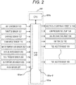
- FIG. 2 is a diagram showing an example of the input-output relationship of the internal combustion engine control unit 101 shown in FIG. 1 .
- the internal combustion engine control unit 101 is composed of an LSI 101a for I/O including an A/D converter 101a-1, a central processing unit (CPU) 101b for executing arithmetic processing, and the like.
- the internal combustion engine control unit 101 receives signals as input, such as signals of various sensors including the air flow sensor 103, the throttle sensor 107, the cam angle sensor 121, the crank angle sensor 116, the water temperature sensor 202, the air-fuel ratio sensor 203, a fuel pressure sensor 204, the oil temperature sensor 205, the knock sensor 207, and executes a predetermined arithmetic processes.
- Control signals are output to the electrically controlled throttle valve 104, the low-pressure fuel pump 128, the high-pressure fuel pump 108, the ignition coil 110, and a plurality of fuel injection valves 109, which are actuators, according to the calculated arithmetic results and the common rail internal combustion pressure control, fuel injection quantity control, ignition timing control and the like are executed.
- the LSI 101a for I/O is provided with a drive circuit 101a-2 for driving each of the fuel injection valves 109.
- the drive circuit 101a-2 boosts the voltage supplied from the battery with a boosting circuit (not shown), controls the current with an integrated circuit (IC) (not shown), and drives each of the fuel injection valves 109 with the controlled current.
- a boosting circuit not shown
- IC integrated circuit
- FIG. 3 is an overall configuration diagram of a fuel system including the high-pressure fuel pump 108 shown in FIG. 1 .
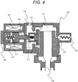
- FIG. 4 is a cross-sectional view of the high-pressure fuel pump 108 shown in FIG. 3 .
- the fuel is sucked by the low-pressure fuel pump 128 from the tank 127, and is regulated to a constant pressure by the pressure regulator 129, and then guided to a fuel intake port 302 of the high-pressure fuel pump 108. Thereafter, the fuel is pressurized to a high pressure by the high-pressure fuel pump 108 and fed under pressure from a fuel discharge port 304 to the common rail 117.
- the fuel injection valve 109 and the fuel pressure sensor 204 are mounted on the common rail 117.
- the injector 109 is mounted according to the number of cylinders of the engine, and injects fuel in accordance with the drive current supplied from the internal combustion engine control unit 101.
- the fuel pressure sensor 204 outputs the acquired fuel pressure data to the internal combustion engine control unit 101.
- the internal combustion engine control unit 101 calculates an appropriate injection fuel quantity, fuel pressure and the like on the basis of the engine state quantity (for example, crank rotation angle, throttle opening, engine speed, fuel pressure, etc.) obtained from various sensors, and controls the high-pressure fuel pump 108 and the fuel injection valve 109.
- the high-pressure fuel pump 108 pressurizes the fuel from the fuel tank 127 and feeds under pressure, the high pressure fuel to the common rail 117.
- the fuel intake port 302, the fuel discharge port 304, and a fuel pressurizing chamber 303 are formed in the high-pressure fuel pump 108.
- a piston plunger 305 as a pressurizing member is slidably held in the fuel pressurizing chamber 303.
- the fuel discharge port 304 is provided with a fuel discharge valve 306 in order to prevent the high pressure fuel on the downstream side from flowing back to the pressurizing chamber.
- a fuel intake valve 310 for controlling intake of fuel is provided downstream of the fuel intake port 302.
- the fuel intake valve 310 opens when the electromagnetic valve solenoid 301 is deenergized, and closes when the electromagnetic valve solenoid 301 is energized.
- the piston plunger 305 reciprocates via a lifter 309 pressed against a pump drive cam 307 which rotates in accordance with the rotation of the camshaft 120 of the exhaust valve 122 in the engine 1 and changes the volume of the fuel pressurizing chamber 303.
- a plunger rod 308 is electromagnetically driven. That is, at the time of energization, the plunger rod 308 is magnetically drawn in the valve-closing direction of the fuel intake valve 310 (left direction in FIG. 4 ).
- the fuel intake valve 310 is provided next to the plunger rod 308.
- the plunger rod 308 is formed separately from the fuel intake valve 310.
- the flange portion formed on the fuel intake valve 310 faces a valve seat 312 formed in a valve housing 311.
- a plunger rod biasing spring 313 is provided at the other end of the plunger rod 308 and biases the plunger rod 308 in the direction in which the fuel intake valve 310 separates from the valve seat 312.
- the plunger rod biasing spring 313 (elastic member) biases the plunger rod 308 in the valve-opening direction of the fuel intake valve 310 (right direction in FIG. 4 ).
- the fuel intake valve 310 is held reciprocably between the valve seat 312 and a valve stopper 314.
- a fuel intake valve biasing spring 315 is disposed between the fuel intake valve 310 and the valve stopper 314.
- the fuel intake valve 310 is biased in a direction away from the valve stopper 314 by the fuel intake valve biasing spring 315.
- the plunger rod biasing spring 313 is constituted by a stronger spring.
- the plunger rod 308 presses the fuel intake valve 310 in a direction away from the valve seat against the force of the intake valve biasing spring 315, and as a result, presses the fuel intake valve 310 against the valve stopper 314.
- the plunger rod 308 is biased in the direction to open the fuel intake valve 310 by the plunger rod biasing spring 313 via the plunger rod 308, and the fuel intake valve 310 is kept at the opened position.
- FIG. 5 is an operation timing chart of the high-pressure fuel pump 108 shown in FIG. 3 .
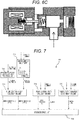
- FIGS. 6A to 6C are schematic views showing the operation of the plunger rod 308 and the fuel intake valve 310 of the high-pressure fuel pump 108 shown in FIG. 3 .
- the fuel discharge of the high-pressure fuel pump 108 is operated by opening and closing the fuel intake valve 310, and the opening and closing of the fuel intake valve 310 is operated by energizing/deenergizing the electromagnetic valve solenoid 301 by the internal combustion engine control unit 101.
- the internal combustion engine control unit 101 calculates an appropriate energization timing to control the electromagnetic valve solenoid 301. Thereby, the fuel pressure in the common rail 117 can be subjected to feedback control to the target value.
- FIG. 7 is a block diagram for illustrating the control of the internal combustion engine control unit 101 shown in FIG. 1 .
- the internal combustion engine control unit 101 includes a fuel pressure input processing unit 701, a target fuel pressure calculation unit 702, a pump control angle calculation unit 703, a pump control duty calculation unit 704, a pump state transition determination unit 705, and a solenoid drive unit 706.
- the fuel pressure input processing unit 701 conducts filter processing for the signal from the fuel pressure sensor 204 and outputs the actual fuel pressure (measured fuel pressure) to the pump control angle calculation unit 703.
- the target fuel pressure calculation unit 702 calculates an optimum target fuel pressure for the operating point from the engine speed and the load, and outputs the calculated target fuel pressure to the pump control angle calculation unit 703.
- the pump control angle calculation unit 703 calculates a phase parameter (energization start angle, energization end angle) for controlling the discharge flow rate of the high-pressure fuel pump 108, and outputs the calculated phase parameter to the solenoid drive unit 706.
- the pump control duty calculation unit 704 calculates a parameter (initial energization time, duty ratio) of a duty signal as a pump drive signal on the basis of the operating condition (engine state quantity), and outputs the calculated duty signal parameter to a solenoid drive unit 706.
- the pump state transition determination unit 705 determines the state of the cylinder injection engine 1, and outputs the determined state (control state) to the solenoid drive unit 706 in order to shift the pump control mode.
- the solenoid drive unit 706 supplies a current generated from the duty signal to the electromagnetic valve solenoid 301.
- the period during which the piston plunger 305 is descending is the intake stroke.
- the volume of the fuel pressurizing chamber 303 increases due to the downward movement of the piston plunger 305, and the pressure decreases.
- the valve closing force of the fuel intake valve 310 due to the pressure of the fuel pressurizing chamber 303 disappears and a valve opening force due to the differential pressure is generated.
- the plunger rod 308 continues to bias the fuel intake valve 310 in the valve-opening direction and starts moving together therewith in the valve-opening direction.
- the plunger rod 308 is formed as a separate member from the fuel intake valve 310, but moves together with the fuel intake valve 310 in the valve-opening direction.
- the period while the piston plunger 305 is ascending is the pressurizing stroke.
- the fuel pressurizing chamber 303 is filled with fuel, and the electromagnetic valve solenoid 301 is in a non-electricity supplied state.
- the plunger rod 308 biases the fuel intake valve 310 in the valve-opening direction by the biasing force of the plunger rod biasing spring 313.
- the electromagnetic valve solenoid 301 maintains a non-electricity supplied state for a predetermined period in accordance with the operation state of the engine. While the fuel intake valve 310 is maintained in the open valve state, the fuel sucked into the fuel pressurizing chamber 303 is spilled (overflowed) . The longer the spilling period is, the smaller the flow rate that the pump compresses is.
- the internal combustion engine control unit 101 adjusts the amount of fuel that the high-pressure fuel pump compresses by adjusting the length of this fuel spill period.
- the internal combustion engine control unit 101 supplies the electromagnetic valve solenoid 301 with electricity.
- the current flowing through the electromagnetic valve solenoid 301 rises with a delay due to the solenoid inherent inductance.
- the magnetic attractive force also increases, and when the magnetic attractive force becomes larger than the biasing force of the plunger rod biasing spring 313, the plunger rod 308 starts to move.
- the plunger rod 308 strikes a fixed core 316, the plunger rod 308 completes its movement.
- the valve closing command current to be applied to the electromagnetic valve solenoid 301 is set so that the magnetic attractive force becomes larger than the biasing force of the plunger rod biasing spring 313, but if an excessive current is applied more than necessary, excessive heat is generated.
- a current control circuit is applied to reduce the amount of heat generation.
- the same effect can be obtained when the timing at which the predetermined current will be reached is set in advance and the current supply amount is subjected to duty control.
- the internal combustion engine control unit 101 functions as a first control unit for applying a first current to the electromagnetic valve solenoid 301 in order to close the fuel intake valve 310.
- the intake valve 310 When the plunger rod 308 is drawn toward the fixed core 316, the intake valve 310 is disengaged from the plunger rod 308. Therefore, the intake valve 310 starts to move in the valve-closing direction by the biasing force of the intake valve biasing spring 315 and the fluid force generated by the fuel flow.
- the intake valve 310 comes into contact with the valve seat 312 to establish the valve closing state. At this time, the engagement of the plunger rod 308 with the intake valve 310 is completely released, and a gap is formed between the tip of the plunger rod 308 and the bottom flat portion of the intake valve 310.
- the plunger rod 308 and the intake valve 310 may be separated in some cases.
- the plunger rod 308 may move together with the intake valve 310.
- the intake valve 310 When a driving current is applied to the electromagnetic valve solenoid 301 at a certain timing during the compression stroke, the intake valve 310 is closed, the fuel in the fuel pressurizing chamber 303 is pressurized and discharged toward the fuel discharge port 304.
- the timing of applying the drive current to the electromagnetic valve solenoid 301 is earlier, the volume of the pressurized fuel is larger, and when the timing is later, the volume of the pressurized fuel becomes smaller.
- the internal combustion engine control unit 101 can control the discharge flow rate of the high-pressure fuel pump 108 by controlling the timing of closing the intake valve 310.
- the supply current can be reduced to a current value lower than the valve closing command current. Since the plunger rod 308 is moving in the valve-closing direction or has finished its movement, the magnetic gap between the opposing faces of the fixed core 316 and the plunger rod 308 has become narrow. Thus, with a current value lower than the valve closing command current value, a larger magnetic attractive force is generated and the plunger rod 308 can be drawn in the valve-closing direction. At this time, it is sufficient that the current value is equal to or greater than the degree that the plunger rod 308 can be attracted and held (generally referred to as holding current) . As a result, heat generation of the solenoid and the power consumption can be reduced.
- FIG. 8 is an operation timing chart of the high-pressure fuel pump 108 used in the high-pressure fuel supply device of the internal combustion engine according to the embodiment of the present invention.
- the internal combustion engine control unit 101 functions as a second control unit that applies the second current to the electromagnetic valve solenoid 301 before the plunger rod 308 collides with the fuel intake valve 310 by the biasing force of the plunger rod biasing spring 313 (elastic member).
- the timing at which the second current is applied is the timing when a predetermined time has elapsed since the valve closing command current (first current) is cut off. The predetermined time is set on the basis of experimental values and the like.
- the value of the current to be supplied needs to be a somewhat low value.
- the internal combustion engine control unit 101 functions as a third control unit that cuts off the valve closing command current (first current) and that sets the current of the electromagnetic valve solenoid 301 to zero. This makes it easier for the plunger rod 308 to separate from the fixed core 316 when the current is cut off. In addition, power consumption of the electromagnetic valve solenoid 301 can be suppressed.
- control method described above is particularly effective in the idling state of the vehicle where quietness is especially required, the control method may be applied only under specific conditions such as the idling state.
- the collision speed of the plunger rod 308 during the intake process can be reduced, and the collision noise of the plunger rod 308 can be accurately reduced.
- the internal combustion engine control unit 101 detects the position of the plunger rod 308.
- the internal combustion engine control unit 101 stores information on the relationship between time and the position (displacement) of the plunger rod 308 when the current shown in FIG. 8 is applied in the built-in memory (storage device) of the internal combustion engine control unit 101.
- the internal combustion engine control unit 101 position detecting unit detects the position of the plunger rod based on the measured value of the current of the electromagnetic valve solenoid 301.
- the internal combustion engine control unit 101 applies the second current to the electromagnetic valve solenoid 301 before the position of the plunger rod 308 reaches the collision position indicating the position where the plunger rod 308 and the fuel intake valve 310 collide with each other.
- the internal combustion engine control unit 101 applies the second current to the electromagnetic valve solenoid 301.
- the relationship shown in FIG. 8 is stored in the internal memory of the internal combustion engine control unit 101, but the relationship may be stored in the external memory (storage device).
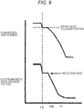
- the internal combustion engine control unit 101 detects an inflection point from the measured value of the voltage of the electromagnetic valve solenoid 301 with the elapse of time after cutting off the valve closing command current (first current), and estimates the position of the plunger rod 308 at the time of the inflection point as the collision position.
- FIG. 9 is a diagram showing the relationship between the displacement of the plunger rod 308 and the voltage of the electromagnetic valve solenoid 301 over the lapse of time.
- the position (displacement) of the plunger rod 308 at the time t1 of the inflection point can be estimated as the collision position.
- the internal combustion engine control unit 101 determines the timing of applying the second current by using the estimated collision position. To be more specific, for example, when the position of the plunger rod 308 is within a predetermined distance from the estimated collision position, the internal combustion engine control unit 101 applies the second current to the electromagnetic valve solenoid 301.
- the collision position is estimated based on the inflection point of the voltage of the electromagnetic valve solenoid 301 in the present modification example, the collision position may be estimated based on the inflection point of the current of the electromagnetic valve solenoid 301.
- timing of applying the second current may be determined by using the estimated statistical values of the collision position (average value, median value, mode, etc.).
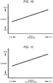
- the internal combustion engine control unit 101 reduces (lowers) the second current as the temperature correlated with the speed of the intake valve increases. That is, the current value of the second current is corrected according to the temperature correlated with the speed of the intake valve.
- the temperature correlated with the speed of the intake valve is, for example, the temperature of the cooling water, the temperature of the lubricating oil, or the temperature of the fuel.
- the internal combustion engine control unit 101 increases (raises) the second current as the fuel pressure increases. That is, the current value of the second current is corrected according to the fuel pressure.
- the internal combustion engine control unit 101 increases (raises) the second current as the engine speed increases. That is, the current value of the second current is corrected according to the engine speed.
- controllable time becomes relatively shorter as the engine speed becomes higher, and thus a large current needs to be applied in a short time.
Landscapes
- Engineering & Computer Science (AREA)
- Chemical & Material Sciences (AREA)
- Combustion & Propulsion (AREA)
- Mechanical Engineering (AREA)
- General Engineering & Computer Science (AREA)
- Physics & Mathematics (AREA)
- Electromagnetism (AREA)
- Fuel-Injection Apparatus (AREA)
- Electrical Control Of Air Or Fuel Supplied To Internal-Combustion Engine (AREA)
Claims (9)
- Dispositif d'alimentation en carburant à haute pression pour un moteur à combustion interne, comprenant :une pompe à carburant à haute pression (108) incluant une vanne d'admission (310), une tige de piston (308) qui est formée en tant que partie séparée de la vanne d'admission (310), un élément élastique (313) qui sollicite la tige de piston (308) dans une direction d'ouverture de vanne d'admission (310) et un solénoïde (301) qui tire la tige de piston (308) dans une direction de fermeture de la vanne d'admission (310) quand elle est alimentée en électricité ; etun dispositif de commande (101) incluant une première unité de commande qui applique un premier courant à solénoïde (301) pour fermer la vanne d'admission (310) et une deuxième unité de commande qui applique un deuxième courant au solénoïde (301) avant que la tige de piston (308) entre en collision avec la vanne d'admission (310) du fait de la force de sollicitation de l'élément élastique (313),dans lequel le dispositif de commande (101) comprend en outre une unité de détection de position qui détecte une position de la tige de piston (308) sur la base d'une valeur de mesure d'un courant ou d'une tension du solénoïde (301), etla deuxième unité de commande applique le deuxième courant au solénoïde (301) avant qu'une position de la tige de piston (308) atteigne une position de collision indiquant une position où la tige de piston (308) et la vanne d'admission (310) entrent en collision l'une avec l'autre.
- Dispositif d'alimentation en carburant à haute pression pour un moteur à combustion interne selon la revendication 1, dans lequel une valeur actuelle du deuxième courant est inférieure à une valeur de courant de crête indiquant une valeur maximum du premier courant.
- Dispositif d'alimentation en carburant à haute pression pour un moteur à combustion interne selon la revendication 1, dans lequel le dispositif de commande (101) comprend en outre une troisième unité de commande qui coupe le premier courant et qui établit un courant du solénoïde (301) à zéro.
- Dispositif d'alimentation en carburant à haute pression pour un moteur à combustion interne selon la revendication 1,
dans lequel le dispositif de commande (101) comprend en outre une unité d'estimation qui détecte un point d'inflexion à partir d'une valeur mesurée d'une tension du solénoïde (301) avec un laps de temps après que la troisième unité de commande coupe le premier courant et qui estime la position de la tige de piston (308) à un moment du point d'inflexion à titre de position de collision, et
la deuxième unité de commande détermine la temporisation d'application du deuxième courant en utilisant la position de collision estimée. - Dispositif d'alimentation en carburant à haute pression pour un moteur à combustion interne selon la revendication 4, dans lequel la deuxième unité de commande détermine la temporisation d'application du deuxième courant en utilisant une valeur statistique de la position de collision estimée.
- Dispositif d'alimentation en carburant à haute pression pour un moteur à combustion interne selon la revendication 1, dans lequel la deuxième unité de commande diminue le deuxième courant quand une température en corrélation avec une vitesse de la vanne d'admission (310) augmente.
- Dispositif d'alimentation en carburant à haute pression pour un moteur à combustion interne selon la revendication 6, dans lequel la température est une température d'eau de refroidissement, une température d'huile de lubrification ou une température de carburant.
- Dispositif d'alimentation en carburant à haute pression pour un moteur à combustion interne selon la revendication 1, dans lequel la deuxième unité de commande augmente le deuxième courant quand la pression de carburant augmente.
- Dispositif d'alimentation en carburant à haute pression pour un moteur à combustion interne selon la revendication 1, dans lequel la deuxième unité de commande augmente le deuxième courant quand une vitesse de rotation du moteur augmente.
Applications Claiming Priority (2)
| Application Number | Priority Date | Filing Date | Title |
|---|---|---|---|
| JP2015009782 | 2015-01-21 | ||
| PCT/JP2016/050601 WO2016117400A1 (fr) | 2015-01-21 | 2016-01-12 | Appareil d'alimentation en carburant à haute pression pour moteur à combustion interne |
Publications (3)
| Publication Number | Publication Date |
|---|---|
| EP3249213A1 EP3249213A1 (fr) | 2017-11-29 |
| EP3249213A4 EP3249213A4 (fr) | 2018-08-22 |
| EP3249213B1 true EP3249213B1 (fr) | 2020-01-08 |
Family
ID=56416947
Family Applications (1)
| Application Number | Title | Priority Date | Filing Date |
|---|---|---|---|
| EP16740007.6A Active EP3249213B1 (fr) | 2015-01-21 | 2016-01-12 | Appareil d'alimentation en carburant à haute pression pour moteur à combustion interne |
Country Status (5)
| Country | Link |
|---|---|
| US (1) | US10557445B2 (fr) |
| EP (1) | EP3249213B1 (fr) |
| JP (1) | JP6461203B2 (fr) |
| CN (1) | CN107110095B (fr) |
| WO (1) | WO2016117400A1 (fr) |
Families Citing this family (10)
| Publication number | Priority date | Publication date | Assignee | Title |
|---|---|---|---|---|
| DE102016218426B3 (de) * | 2016-09-26 | 2018-02-01 | Continental Automotive Gmbh | Verfahren zum Betreiben einer Hochdruckpumpe eines Hochdruckeinspritzsystems eines Kraftfahrzeugs sowie Steuervorrichtung und Kraftfahrzeug |
| DE102016219959B4 (de) * | 2016-10-13 | 2018-06-21 | Continental Automotive Gmbh | Verfahren zum Überprüfen einer Kalibrierung eines Drucksensors eines Kraftfahrzeug-Einspritzsystems sowie Steuervorrichtung, Hochdruckeinspritzsystem und Kraftfahrzeug |
| DE102016219956B3 (de) * | 2016-10-13 | 2017-08-17 | Continental Automotive Gmbh | Verfahren zum Einstellen eines Dämpfungsstroms eines Einlassventils eines Kraftfahrzeug-Hochdruckeinspritzsystems, sowie Steuervorrichtung, Hochdruckeinspritzsystem und Kraftfahrzeug |
| DE102017204482A1 (de) * | 2017-03-17 | 2018-09-20 | Robert Bosch Gmbh | Verfahren zum Betreiben einer Hochdruckpumpe |
| DE102017205884B4 (de) | 2017-04-06 | 2024-06-06 | Vitesco Technologies GmbH | Verfahren zum Schalten eines Stromes in einem Elektromagneten eines schaltbaren Magnet-Ventils sowie elektronische Schaltung, Magnet-Ventil, Pumpe und Kraftfahrzeug |
| US11053903B2 (en) * | 2017-06-27 | 2021-07-06 | Hitachi Automotive Systems, Ltd. | High-pressure fuel supply pump |
| JP7120132B2 (ja) * | 2019-04-10 | 2022-08-17 | トヨタ自動車株式会社 | 内燃機関の制御装置 |
| JP7115399B2 (ja) | 2019-04-10 | 2022-08-09 | トヨタ自動車株式会社 | 内燃機関の制御装置 |
| DE112020003215B4 (de) * | 2019-09-19 | 2025-07-24 | Hitachi Astemo, Ltd. | Elektromagnetisches Einlassventil und Hochdruckkraftstoffversorgungspumpe |
| US12031458B2 (en) * | 2019-12-27 | 2024-07-09 | Yuri Gavriluk | Internal combustion engine with a high-pressure fuel pump |
Family Cites Families (19)
| Publication number | Priority date | Publication date | Assignee | Title |
|---|---|---|---|---|
| JP3428443B2 (ja) | 1998-06-29 | 2003-07-22 | 株式会社日立製作所 | 可変流量高圧燃料ポンプ及び燃料供給制御方法 |
| EP1477665B1 (fr) | 1999-02-09 | 2008-04-23 | Hitachi, Ltd. | Pompe d'alimentation en combustible à haute pression pour moteur à combustion interne |
| DE102007035316B4 (de) * | 2007-07-27 | 2019-12-24 | Robert Bosch Gmbh | Verfahren zur Steuerung eines Magnetventils einer Mengensteuerung in einer Brennkraftmaschine |
| JP4587133B2 (ja) | 2008-06-04 | 2010-11-24 | 株式会社デンソー | 燃料供給装置 |
| DE102008054512B4 (de) * | 2008-12-11 | 2021-08-05 | Robert Bosch Gmbh | Verfahren zum Betreiben eines Kraftstoffeinspritzsystems einer Brennkraftmaschine |
| DE102009027311A1 (de) * | 2009-06-30 | 2011-01-05 | Robert Bosch Gmbh | Verfahren zum Betreiben einer Brennkraftmaschine |
| US8677977B2 (en) * | 2010-04-30 | 2014-03-25 | Denso International America, Inc. | Direct injection pump control strategy for noise reduction |
| EP2453122B1 (fr) * | 2010-11-12 | 2016-09-07 | Hitachi, Ltd. | Procédé et appareil de contrôle pour commander une pompe à carburant à haute pression configurée pour fournir de l'alimentation pressurisée à un moteur à combustion interne |
| JP5798799B2 (ja) * | 2011-05-30 | 2015-10-21 | 日立オートモティブシステムズ株式会社 | 電磁駆動型の吸入弁を備えた高圧燃料供給ポンプ |
| JP5639970B2 (ja) * | 2011-08-03 | 2014-12-10 | 日立オートモティブシステムズ株式会社 | 電磁弁の制御方法、高圧燃料供給ポンプの電磁吸入弁の制御方法および電磁吸入弁の電磁駆動機構の制御装置 |
| US9341181B2 (en) * | 2012-03-16 | 2016-05-17 | Denso Corporation | Control device of high pressure pump |
| DE102012211798B4 (de) * | 2012-07-06 | 2019-12-05 | Robert Bosch Gmbh | Verfahren zur Betätigung eines Schaltelements einer Ventileinrichtung |
| JP6044366B2 (ja) * | 2013-01-30 | 2016-12-14 | 株式会社デンソー | 高圧ポンプの制御装置 |
| DE102013206674A1 (de) * | 2013-04-15 | 2014-10-16 | Robert Bosch Gmbh | Verfahren und Vorrichtung zur Ansteuerung eines Mengensteuerventils |
| DE102014206442B4 (de) * | 2014-04-03 | 2019-02-14 | Continental Automotive Gmbh | Verfahren und Vorrichtung zum Betreiben eines Druckspeichers, insbesondere für Common-Rail-Einspritzsysteme in der Kfz-Technik |
| JP6265091B2 (ja) * | 2014-09-19 | 2018-01-24 | 株式会社デンソー | 高圧ポンプの制御装置 |
| JP2016205365A (ja) * | 2015-04-24 | 2016-12-08 | 株式会社デンソー | 高圧ポンプの制御装置 |
| JP6464972B2 (ja) * | 2015-09-24 | 2019-02-06 | 株式会社デンソー | 高圧ポンプ制御装置 |
| JP6569542B2 (ja) * | 2016-01-21 | 2019-09-04 | 株式会社デンソー | 高圧ポンプ制御装置 |
-
2016
- 2016-01-12 EP EP16740007.6A patent/EP3249213B1/fr active Active
- 2016-01-12 JP JP2016570578A patent/JP6461203B2/ja active Active
- 2016-01-12 CN CN201680004421.9A patent/CN107110095B/zh active Active
- 2016-01-12 US US15/536,689 patent/US10557445B2/en active Active
- 2016-01-12 WO PCT/JP2016/050601 patent/WO2016117400A1/fr not_active Ceased
Non-Patent Citations (1)
| Title |
|---|
| None * |
Also Published As
| Publication number | Publication date |
|---|---|
| JP6461203B2 (ja) | 2019-01-30 |
| CN107110095A (zh) | 2017-08-29 |
| US20170342935A1 (en) | 2017-11-30 |
| WO2016117400A1 (fr) | 2016-07-28 |
| EP3249213A4 (fr) | 2018-08-22 |
| CN107110095B (zh) | 2019-07-09 |
| JPWO2016117400A1 (ja) | 2017-09-21 |
| EP3249213A1 (fr) | 2017-11-29 |
| US10557445B2 (en) | 2020-02-11 |
Similar Documents
| Publication | Publication Date | Title |
|---|---|---|
| EP3249213B1 (fr) | Appareil d'alimentation en carburant à haute pression pour moteur à combustion interne | |
| EP2848794B1 (fr) | Appareil de contrôle de pompe à carburant haute pression pour moteur à combustion interne | |
| EP2169203B1 (fr) | Appareil de contrôle de pompe à carburant haute pression pour moteur à combustion interne | |
| JP2008215321A (ja) | 内燃機関の高圧燃料ポンプ制御装置 | |
| US8079345B2 (en) | High pressure fuel supply control system for internal combustion engine | |
| US11859584B2 (en) | Solenoid valve control device | |
| CN1952381B (zh) | 带容量控制机构的高压燃料供给泵的控制器 | |
| JP6044366B2 (ja) | 高圧ポンプの制御装置 | |
| JP5497556B2 (ja) | エンジンの制御装置 | |
| JP2002188545A (ja) | 筒内噴射エンジンの高圧燃料ポンプ制御装置 | |
| US11519372B2 (en) | Control device for high-pressure pump and method for controlling the same | |
| WO2015151945A1 (fr) | Dispositif de commande pour moteur à combustion interne | |
| JP2020159205A (ja) | 燃料噴射装置の制御装置 | |
| JP5470363B2 (ja) | 内燃機関の高圧燃料ポンプ制御装置 | |
| JP2013194531A (ja) | 高圧ポンプの制御装置 | |
| JP6063793B2 (ja) | 内燃機関の制御装置 | |
| US10473077B2 (en) | Control device for high-pressure pump | |
| JP2023157225A (ja) | 高圧燃料ポンプの制御装置 | |
| JP4969611B2 (ja) | 内燃機関の高圧燃料ポンプ制御装置 | |
| JP2015161294A (ja) | 燃料ポンプ |
Legal Events
| Date | Code | Title | Description |
|---|---|---|---|
| STAA | Information on the status of an ep patent application or granted ep patent |
Free format text: STATUS: THE INTERNATIONAL PUBLICATION HAS BEEN MADE |
|
| PUAI | Public reference made under article 153(3) epc to a published international application that has entered the european phase |
Free format text: ORIGINAL CODE: 0009012 |
|
| STAA | Information on the status of an ep patent application or granted ep patent |
Free format text: STATUS: REQUEST FOR EXAMINATION WAS MADE |
|
| 17P | Request for examination filed |
Effective date: 20170821 |
|
| AK | Designated contracting states |
Kind code of ref document: A1 Designated state(s): AL AT BE BG CH CY CZ DE DK EE ES FI FR GB GR HR HU IE IS IT LI LT LU LV MC MK MT NL NO PL PT RO RS SE SI SK SM TR |
|
| AX | Request for extension of the european patent |
Extension state: BA ME |
|
| DAV | Request for validation of the european patent (deleted) | ||
| DAX | Request for extension of the european patent (deleted) | ||
| A4 | Supplementary search report drawn up and despatched |
Effective date: 20180720 |
|
| RIC1 | Information provided on ipc code assigned before grant |
Ipc: F02D 41/40 20060101ALI20180716BHEP Ipc: F02M 59/36 20060101AFI20180716BHEP Ipc: F02M 59/46 20060101ALI20180716BHEP Ipc: F02M 51/04 20060101ALI20180716BHEP Ipc: F02M 63/00 20060101ALI20180716BHEP Ipc: F02M 59/44 20060101ALI20180716BHEP |
|
| GRAP | Despatch of communication of intention to grant a patent |
Free format text: ORIGINAL CODE: EPIDOSNIGR1 |
|
| STAA | Information on the status of an ep patent application or granted ep patent |
Free format text: STATUS: GRANT OF PATENT IS INTENDED |
|
| INTG | Intention to grant announced |
Effective date: 20190723 |
|
| RIN1 | Information on inventor provided before grant (corrected) |
Inventor name: OKAMOTO, TAKASHI Inventor name: ARIHARA, YOSHINOBU |
|
| GRAS | Grant fee paid |
Free format text: ORIGINAL CODE: EPIDOSNIGR3 |
|
| GRAA | (expected) grant |
Free format text: ORIGINAL CODE: 0009210 |
|
| STAA | Information on the status of an ep patent application or granted ep patent |
Free format text: STATUS: THE PATENT HAS BEEN GRANTED |
|
| AK | Designated contracting states |
Kind code of ref document: B1 Designated state(s): AL AT BE BG CH CY CZ DE DK EE ES FI FR GB GR HR HU IE IS IT LI LT LU LV MC MK MT NL NO PL PT RO RS SE SI SK SM TR |
|
| REG | Reference to a national code |
Ref country code: GB Ref legal event code: FG4D |
|
| REG | Reference to a national code |
Ref country code: CH Ref legal event code: EP |
|
| REG | Reference to a national code |
Ref country code: DE Ref legal event code: R096 Ref document number: 602016027838 Country of ref document: DE |
|
| REG | Reference to a national code |
Ref country code: IE Ref legal event code: FG4D |
|
| REG | Reference to a national code |
Ref country code: AT Ref legal event code: REF Ref document number: 1223027 Country of ref document: AT Kind code of ref document: T Effective date: 20200215 |
|
| REG | Reference to a national code |
Ref country code: NL Ref legal event code: MP Effective date: 20200108 |
|
| REG | Reference to a national code |
Ref country code: LT Ref legal event code: MG4D |
|
| PG25 | Lapsed in a contracting state [announced via postgrant information from national office to epo] |
Ref country code: FI Free format text: LAPSE BECAUSE OF FAILURE TO SUBMIT A TRANSLATION OF THE DESCRIPTION OR TO PAY THE FEE WITHIN THE PRESCRIBED TIME-LIMIT Effective date: 20200108 Ref country code: NO Free format text: LAPSE BECAUSE OF FAILURE TO SUBMIT A TRANSLATION OF THE DESCRIPTION OR TO PAY THE FEE WITHIN THE PRESCRIBED TIME-LIMIT Effective date: 20200408 Ref country code: RS Free format text: LAPSE BECAUSE OF FAILURE TO SUBMIT A TRANSLATION OF THE DESCRIPTION OR TO PAY THE FEE WITHIN THE PRESCRIBED TIME-LIMIT Effective date: 20200108 Ref country code: PT Free format text: LAPSE BECAUSE OF FAILURE TO SUBMIT A TRANSLATION OF THE DESCRIPTION OR TO PAY THE FEE WITHIN THE PRESCRIBED TIME-LIMIT Effective date: 20200531 Ref country code: NL Free format text: LAPSE BECAUSE OF FAILURE TO SUBMIT A TRANSLATION OF THE DESCRIPTION OR TO PAY THE FEE WITHIN THE PRESCRIBED TIME-LIMIT Effective date: 20200108 Ref country code: LT Free format text: LAPSE BECAUSE OF FAILURE TO SUBMIT A TRANSLATION OF THE DESCRIPTION OR TO PAY THE FEE WITHIN THE PRESCRIBED TIME-LIMIT Effective date: 20200108 |
|
| PG25 | Lapsed in a contracting state [announced via postgrant information from national office to epo] |
Ref country code: GR Free format text: LAPSE BECAUSE OF FAILURE TO SUBMIT A TRANSLATION OF THE DESCRIPTION OR TO PAY THE FEE WITHIN THE PRESCRIBED TIME-LIMIT Effective date: 20200409 Ref country code: HR Free format text: LAPSE BECAUSE OF FAILURE TO SUBMIT A TRANSLATION OF THE DESCRIPTION OR TO PAY THE FEE WITHIN THE PRESCRIBED TIME-LIMIT Effective date: 20200108 Ref country code: LV Free format text: LAPSE BECAUSE OF FAILURE TO SUBMIT A TRANSLATION OF THE DESCRIPTION OR TO PAY THE FEE WITHIN THE PRESCRIBED TIME-LIMIT Effective date: 20200108 Ref country code: IS Free format text: LAPSE BECAUSE OF FAILURE TO SUBMIT A TRANSLATION OF THE DESCRIPTION OR TO PAY THE FEE WITHIN THE PRESCRIBED TIME-LIMIT Effective date: 20200508 Ref country code: SE Free format text: LAPSE BECAUSE OF FAILURE TO SUBMIT A TRANSLATION OF THE DESCRIPTION OR TO PAY THE FEE WITHIN THE PRESCRIBED TIME-LIMIT Effective date: 20200108 Ref country code: BG Free format text: LAPSE BECAUSE OF FAILURE TO SUBMIT A TRANSLATION OF THE DESCRIPTION OR TO PAY THE FEE WITHIN THE PRESCRIBED TIME-LIMIT Effective date: 20200408 |
|
| REG | Reference to a national code |
Ref country code: CH Ref legal event code: PL |
|
| REG | Reference to a national code |
Ref country code: DE Ref legal event code: R097 Ref document number: 602016027838 Country of ref document: DE |
|
| REG | Reference to a national code |
Ref country code: BE Ref legal event code: MM Effective date: 20200131 |
|
| PG25 | Lapsed in a contracting state [announced via postgrant information from national office to epo] |
Ref country code: LU Free format text: LAPSE BECAUSE OF NON-PAYMENT OF DUE FEES Effective date: 20200112 Ref country code: CZ Free format text: LAPSE BECAUSE OF FAILURE TO SUBMIT A TRANSLATION OF THE DESCRIPTION OR TO PAY THE FEE WITHIN THE PRESCRIBED TIME-LIMIT Effective date: 20200108 Ref country code: ES Free format text: LAPSE BECAUSE OF FAILURE TO SUBMIT A TRANSLATION OF THE DESCRIPTION OR TO PAY THE FEE WITHIN THE PRESCRIBED TIME-LIMIT Effective date: 20200108 Ref country code: SK Free format text: LAPSE BECAUSE OF FAILURE TO SUBMIT A TRANSLATION OF THE DESCRIPTION OR TO PAY THE FEE WITHIN THE PRESCRIBED TIME-LIMIT Effective date: 20200108 Ref country code: MC Free format text: LAPSE BECAUSE OF FAILURE TO SUBMIT A TRANSLATION OF THE DESCRIPTION OR TO PAY THE FEE WITHIN THE PRESCRIBED TIME-LIMIT Effective date: 20200108 Ref country code: SM Free format text: LAPSE BECAUSE OF FAILURE TO SUBMIT A TRANSLATION OF THE DESCRIPTION OR TO PAY THE FEE WITHIN THE PRESCRIBED TIME-LIMIT Effective date: 20200108 Ref country code: EE Free format text: LAPSE BECAUSE OF FAILURE TO SUBMIT A TRANSLATION OF THE DESCRIPTION OR TO PAY THE FEE WITHIN THE PRESCRIBED TIME-LIMIT Effective date: 20200108 Ref country code: DK Free format text: LAPSE BECAUSE OF FAILURE TO SUBMIT A TRANSLATION OF THE DESCRIPTION OR TO PAY THE FEE WITHIN THE PRESCRIBED TIME-LIMIT Effective date: 20200108 Ref country code: RO Free format text: LAPSE BECAUSE OF FAILURE TO SUBMIT A TRANSLATION OF THE DESCRIPTION OR TO PAY THE FEE WITHIN THE PRESCRIBED TIME-LIMIT Effective date: 20200108 |
|
| PLBE | No opposition filed within time limit |
Free format text: ORIGINAL CODE: 0009261 |
|
| STAA | Information on the status of an ep patent application or granted ep patent |
Free format text: STATUS: NO OPPOSITION FILED WITHIN TIME LIMIT |
|
| REG | Reference to a national code |
Ref country code: AT Ref legal event code: MK05 Ref document number: 1223027 Country of ref document: AT Kind code of ref document: T Effective date: 20200108 |
|
| PG25 | Lapsed in a contracting state [announced via postgrant information from national office to epo] |
Ref country code: LI Free format text: LAPSE BECAUSE OF NON-PAYMENT OF DUE FEES Effective date: 20200131 Ref country code: BE Free format text: LAPSE BECAUSE OF NON-PAYMENT OF DUE FEES Effective date: 20200131 Ref country code: CH Free format text: LAPSE BECAUSE OF NON-PAYMENT OF DUE FEES Effective date: 20200131 |
|
| 26N | No opposition filed |
Effective date: 20201009 |
|
| PG25 | Lapsed in a contracting state [announced via postgrant information from national office to epo] |
Ref country code: IE Free format text: LAPSE BECAUSE OF NON-PAYMENT OF DUE FEES Effective date: 20200112 Ref country code: FR Free format text: LAPSE BECAUSE OF NON-PAYMENT OF DUE FEES Effective date: 20200308 Ref country code: IT Free format text: LAPSE BECAUSE OF FAILURE TO SUBMIT A TRANSLATION OF THE DESCRIPTION OR TO PAY THE FEE WITHIN THE PRESCRIBED TIME-LIMIT Effective date: 20200108 Ref country code: AT Free format text: LAPSE BECAUSE OF FAILURE TO SUBMIT A TRANSLATION OF THE DESCRIPTION OR TO PAY THE FEE WITHIN THE PRESCRIBED TIME-LIMIT Effective date: 20200108 |
|
| PG25 | Lapsed in a contracting state [announced via postgrant information from national office to epo] |
Ref country code: PL Free format text: LAPSE BECAUSE OF FAILURE TO SUBMIT A TRANSLATION OF THE DESCRIPTION OR TO PAY THE FEE WITHIN THE PRESCRIBED TIME-LIMIT Effective date: 20200108 Ref country code: SI Free format text: LAPSE BECAUSE OF FAILURE TO SUBMIT A TRANSLATION OF THE DESCRIPTION OR TO PAY THE FEE WITHIN THE PRESCRIBED TIME-LIMIT Effective date: 20200108 |
|
| REG | Reference to a national code |
Ref country code: DE Ref legal event code: R082 Ref document number: 602016027838 Country of ref document: DE Representative=s name: MERH-IP MATIAS ERNY REICHL HOFFMANN PATENTANWA, DE Ref country code: DE Ref legal event code: R081 Ref document number: 602016027838 Country of ref document: DE Owner name: HITACHI ASTEMO, LTD., HITACHINAKA-SHI, JP Free format text: FORMER OWNER: HITACHI AUTOMOTIVE SYSTEMS, LTD., HITACHINAKA-SHI, IBARAKI, JP |
|
| GBPC | Gb: european patent ceased through non-payment of renewal fee |
Effective date: 20200408 |
|
| PG25 | Lapsed in a contracting state [announced via postgrant information from national office to epo] |
Ref country code: GB Free format text: LAPSE BECAUSE OF NON-PAYMENT OF DUE FEES Effective date: 20200408 |
|
| PG25 | Lapsed in a contracting state [announced via postgrant information from national office to epo] |
Ref country code: TR Free format text: LAPSE BECAUSE OF FAILURE TO SUBMIT A TRANSLATION OF THE DESCRIPTION OR TO PAY THE FEE WITHIN THE PRESCRIBED TIME-LIMIT Effective date: 20200108 Ref country code: MT Free format text: LAPSE BECAUSE OF FAILURE TO SUBMIT A TRANSLATION OF THE DESCRIPTION OR TO PAY THE FEE WITHIN THE PRESCRIBED TIME-LIMIT Effective date: 20200108 Ref country code: CY Free format text: LAPSE BECAUSE OF FAILURE TO SUBMIT A TRANSLATION OF THE DESCRIPTION OR TO PAY THE FEE WITHIN THE PRESCRIBED TIME-LIMIT Effective date: 20200108 |
|
| PG25 | Lapsed in a contracting state [announced via postgrant information from national office to epo] |
Ref country code: MK Free format text: LAPSE BECAUSE OF FAILURE TO SUBMIT A TRANSLATION OF THE DESCRIPTION OR TO PAY THE FEE WITHIN THE PRESCRIBED TIME-LIMIT Effective date: 20200108 Ref country code: AL Free format text: LAPSE BECAUSE OF FAILURE TO SUBMIT A TRANSLATION OF THE DESCRIPTION OR TO PAY THE FEE WITHIN THE PRESCRIBED TIME-LIMIT Effective date: 20200108 |
|
| PGFP | Annual fee paid to national office [announced via postgrant information from national office to epo] |
Ref country code: DE Payment date: 20251203 Year of fee payment: 11 |