EP3249216B1 - Rotorblatt mit einrichtungen zur geräuschreduzierung - Google Patents
Rotorblatt mit einrichtungen zur geräuschreduzierung Download PDFInfo
- Publication number
- EP3249216B1 EP3249216B1 EP16171695.6A EP16171695A EP3249216B1 EP 3249216 B1 EP3249216 B1 EP 3249216B1 EP 16171695 A EP16171695 A EP 16171695A EP 3249216 B1 EP3249216 B1 EP 3249216B1
- Authority
- EP
- European Patent Office
- Prior art keywords
- rotor blade
- noise
- trailing edge
- edge
- suction side
- Prior art date
- Legal status (The legal status is an assumption and is not a legal conclusion. Google has not performed a legal analysis and makes no representation as to the accuracy of the status listed.)
- Active
Links
Images


Classifications
-
- F—MECHANICAL ENGINEERING; LIGHTING; HEATING; WEAPONS; BLASTING
- F03—MACHINES OR ENGINES FOR LIQUIDS; WIND, SPRING, OR WEIGHT MOTORS; PRODUCING MECHANICAL POWER OR A REACTIVE PROPULSIVE THRUST, NOT OTHERWISE PROVIDED FOR
- F03D—WIND MOTORS
- F03D1/00—Wind motors with rotation axis substantially parallel to the air flow entering the rotor
- F03D1/06—Rotors
- F03D1/065—Rotors characterised by their construction elements
-
- F—MECHANICAL ENGINEERING; LIGHTING; HEATING; WEAPONS; BLASTING
- F03—MACHINES OR ENGINES FOR LIQUIDS; WIND, SPRING, OR WEIGHT MOTORS; PRODUCING MECHANICAL POWER OR A REACTIVE PROPULSIVE THRUST, NOT OTHERWISE PROVIDED FOR
- F03D—WIND MOTORS
- F03D7/00—Controlling wind motors
- F03D7/02—Controlling wind motors the wind motors having rotation axis substantially parallel to the air flow entering the rotor
- F03D7/0296—Controlling wind motors the wind motors having rotation axis substantially parallel to the air flow entering the rotor to prevent, counteract or reduce noise emissions
-
- F—MECHANICAL ENGINEERING; LIGHTING; HEATING; WEAPONS; BLASTING
- F03—MACHINES OR ENGINES FOR LIQUIDS; WIND, SPRING, OR WEIGHT MOTORS; PRODUCING MECHANICAL POWER OR A REACTIVE PROPULSIVE THRUST, NOT OTHERWISE PROVIDED FOR
- F03D—WIND MOTORS
- F03D1/00—Wind motors with rotation axis substantially parallel to the air flow entering the rotor
- F03D1/06—Rotors
- F03D1/065—Rotors characterised by their construction elements
- F03D1/0675—Rotors characterised by their construction elements of the blades
-
- F—MECHANICAL ENGINEERING; LIGHTING; HEATING; WEAPONS; BLASTING
- F03—MACHINES OR ENGINES FOR LIQUIDS; WIND, SPRING, OR WEIGHT MOTORS; PRODUCING MECHANICAL POWER OR A REACTIVE PROPULSIVE THRUST, NOT OTHERWISE PROVIDED FOR
- F03D—WIND MOTORS
- F03D17/00—Monitoring or testing of wind motors, e.g. diagnostics
-
- F—MECHANICAL ENGINEERING; LIGHTING; HEATING; WEAPONS; BLASTING
- F05—INDEXING SCHEMES RELATING TO ENGINES OR PUMPS IN VARIOUS SUBCLASSES OF CLASSES F01-F04
- F05B—INDEXING SCHEME RELATING TO WIND, SPRING, WEIGHT, INERTIA OR LIKE MOTORS, TO MACHINES OR ENGINES FOR LIQUIDS COVERED BY SUBCLASSES F03B, F03D AND F03G
- F05B2260/00—Function
- F05B2260/96—Preventing, counteracting or reducing vibration or noise
- F05B2260/962—Preventing, counteracting or reducing vibration or noise by means creating "anti-noise"
-
- F—MECHANICAL ENGINEERING; LIGHTING; HEATING; WEAPONS; BLASTING
- F05—INDEXING SCHEMES RELATING TO ENGINES OR PUMPS IN VARIOUS SUBCLASSES OF CLASSES F01-F04
- F05B—INDEXING SCHEME RELATING TO WIND, SPRING, WEIGHT, INERTIA OR LIKE MOTORS, TO MACHINES OR ENGINES FOR LIQUIDS COVERED BY SUBCLASSES F03B, F03D AND F03G
- F05B2270/00—Control
- F05B2270/30—Control parameters, e.g. input parameters
- F05B2270/333—Noise or sound levels
-
- Y—GENERAL TAGGING OF NEW TECHNOLOGICAL DEVELOPMENTS; GENERAL TAGGING OF CROSS-SECTIONAL TECHNOLOGIES SPANNING OVER SEVERAL SECTIONS OF THE IPC; TECHNICAL SUBJECTS COVERED BY FORMER USPC CROSS-REFERENCE ART COLLECTIONS [XRACs] AND DIGESTS
- Y02—TECHNOLOGIES OR APPLICATIONS FOR MITIGATION OR ADAPTATION AGAINST CLIMATE CHANGE
- Y02E—REDUCTION OF GREENHOUSE GAS [GHG] EMISSIONS, RELATED TO ENERGY GENERATION, TRANSMISSION OR DISTRIBUTION
- Y02E10/00—Energy generation through renewable energy sources
- Y02E10/70—Wind energy
- Y02E10/72—Wind turbines with rotation axis in wind direction
Definitions
- the present invention relates to a rotor blade which is designed and configured for being exposed to a fluid, wherein flow-induced edge noise of the rotor blade is minimized.
- the invention is furthermore related to a wind turbine with at least one such rotor blade.
- noise is generally generated at the edges of the rotor blade.
- the intensity of the noise and the frequency of the noise depends on many parameters, such as the properties of the fluid and the properties of the edge, namely the size of the edge and the shape of the edge, e.g. whether it is rounded or sharp.
- the noise being generated at the edges is typically undesired.
- noise which is generated by the rotating rotor blades can be perceived as a nuisance by people in the vicinity of the wind turbine.
- wind turbines may either need to be placed further away from residential areas or they have to be operated in such a manner that the maximum allowed level of noise is not exceeded. This means that wind turbines may need to be curtailed in certain conditions because of the flow-induced edge noise.
- WO2008043874 discloses to a system for suppressing and eliminating noise in wind turbines, formed by microphones disposed over the entire span of the blades and the towers.
- US2014142888 discloses a wind turbine system. Where a noise controller implements a noise mitigation measure in response to the detected rotational position of the rotor blade.
- US2012025530 discloses a controlling method for amplitude modulation of noise generated by wind turbines of wind farm.
- US2009097976A1 discloses another system for suppressing and eliminating noise in wind turbines.
- a rotor blade with a leading edge and a trailing edge, wherein the rotor blade is designed and configured for being exposed to a fluid flowing substantially from the leading edge to the trailing edge of the rotor blade.
- the rotor blade comprises a portion which has the shape of an airfoil comprising a pressure side and a suction side, each confined by the trailing edge and the leading edge.
- the rotor blade further comprises
- the present invention describes a method how to reduce or even completely eliminate flow-induced edge noise from a rotor blade.
- This reduction or even elimination of the noise is achieved by the use of anti-noise. Since often times flow-induced edge noise is a broadband noise source, caused by a turbulent flow, the edge noise is random, i.e. stochastic.
- the acoustic pressure fluctuations are nondeterministic, meaning that they cannot be predicted in a temporal sense on the basis of the current or earlier acoustic signals, even when the statistical properties are known.
- the unsteady surface pressure pattern that generates the sound at the edge, can be considered to convect unchanged with the flow along the chord of the rotor blade. Note that in practice this unchanged convection happens until a certain degree. This means that minimum changes of the unsteady surface pressure pattern is possible. This phenomenon is referred to in the literature as the 'frozen turbulence' assumption. In the present invention, this fact is used to detect the unsteady surface pressures upstream of the edge so that a noise cancelling anti-noise signal can be constructed and emitted in anti-phase at the moment when the turbulent eddies, which are responsible for the unsteady surface pressure pattern and noise generation, pass the edge.
- essential components of the inventive arrangement at the rotor blade are at least one sensor for detecting the flow characteristics of the fluid and at least one actuator for producing the anti-noise signal.
- Both the sensor and the actuator are arranged at the surface of the rotor blade. This means that they are somehow integrated or added to the rotor blade at its surface.
- one option is to submerge and insert the sensor and the actuator into the shell or surface part of the rotor blade such that they are in contact with the surrounding air but they do not stick out and produce additional turbulences on the surface of the rotor blade.
- the actuator comprises a membrane.
- the sensor also comprises a membrane.
- the rotor blade comprises a portion which has the shape of an airfoil comprising a pressure side and a suction side, and the pressure side and the suction side are each confined by the trailing edge and the leading edge of the rotor blade.
- the rotor blade is a lift producing rotor blade which has at least partly the shape of an airfoil.
- An airfoil is characterized in that it comprises a pressure side and a suction side and is able to produce lift when it is exposed to a fluid flowing substantially from the leading edge to the trailing edge of the rotor blade.
- the outer surface of such an airfoil shaped rotor blade is characterized by one portion which is referred to as the pressure side and which is confined at one side by the trailing edge and on the other side by the leading edge and the remaining part of the surface is typically referred to as the suction side of the rotor blade.
- the present invention particularly relates to a rotor blade of a wind turbine.
- the inventive concept is not limited to flow-induced edge noise of rotor blades of a wind turbine. It can also be applied to reduce flow-induced edge noise from, for example, aircraft wings, helicopter blades, fans, etc.
- the actuator comprises a loudspeaker.
- a loudspeaker is a well-known and readily available, inexpensive device which can be integrated or added to a rotor blade at almost any size in a simple and inexpensive manner, without affecting the aerodynamic flow around the blade.
- the senor may exemplarily comprise a surface pressure transducer.
- a pressure transducer is also well-known and well-proven and may also be added or implemented and included to a rotor blade without large expenses or changes to the existing rotor blade.
- the flow-induced edge noise which is at least partly cancelled out by the anti-noise signal being produced by the actuator, preferably relates to trailing edge noise of the rotor blade, i.e. to noise which is flow-induced edge noise and which is generated in the trailing edge of the rotor blade.
- the present invention may be applied to other flow-induced edge noise sources as well, such as, for instance, leading edge in-flow turbulence noise or tip noise of the rotor blade.
- the senor is located upstream of the actuator with regard to the flow direction of the fluid.
- the rotor blade is designed and configured for being exposed to the fluid flowing substantially from the leading edge to the trailing edge of the rotor blade; therefore a flow direction can be assigned and defined to the exposed and surrounded rotor blade.
- these are first in a temporal sense detected by the sensor which is located upstream of the actuator and the resulting and produced anti-noise signal can slightly afterwards be emitted or induced by the actuator.
- this preferred embodiment may also be described that the actuator is closer to the trailing edge regarding a chordwise distance than the sensor.
- the senor and the actuator are both located either on the pressure side or on the suction side of the rotor blade.
- the senor is located at the suction side and the actuator is located at the pressure side, or the sensor is located at the pressure side and the actuator is located at the section side.
- connection means such as a tube or a channel.
- the rotor blade may further comprise a control unit for constructing the anti-noise signal and the actuator is connected with the sensor via connection means and the control unit.
- control unit is advantageously located inside the rotor blade, which has the advantage that it does not disturb the air flow which is flowing across the rotor blade and that it is protected from the ambient and the influences of the ambient.
- the actuator may be arranged and prepared to either induce surface pressure cancellation or to emit a sound signal.
- the air flow is somehow manipulated, for example by passive or active aerodynamic devices, in order to obtain a certain (fixed) thickness of the trailing edge boundary layer, so that a tuned (passive or active) anti-noise system can be applied. Having a fixed boundary layer thickness makes it easier to design an effective, tuned anti-noise system.
- the air flow is somehow manipulated such that a particular (fixed) frequency content of the pressure fluctuations is obtained, so that a tuned (passive or active) anti-noise system can be applied.
- the thickness of the boundary layer and/or the frequency of the surface pressure fluctuations could be tuned in order to match a given anti-noise concept.
- This general principle, of manipulating the air flow to obtain a certain thickness of the boundary layer or a specific frequency content of the pressure fluctuations can also be applied to other noise reduction concept, such as e.g. trailing edge serrations.
- the invention is also related to a wind turbine with at least one rotor blade as described in various embodiments above.
- Figure 1 shows a rotor blade 20.
- the rotor blade 20 comprises a root 21 and a tip 22.
- the rotor blade 20 furthermore comprises a leading edge 23 and a trailing edge 24.
- Figure 1 illustrates a top view or planar view onto the rotor blade 20, namely onto the pressure side of the rotor blade.
- the rotor blade 20 is characterized by a span 25, which is a straight line projecting away from the root 21.
- the pitch axis coincides with the span 25 as defined in the context of this patent application.
- chords 26 may be assigned to the rotor blade 20.
- Each chord 26 is oriented perpendicular to the span 25. Therefore, for each spanwise position starting at the root 21 and reaching to the tip 22, a chord 26 may be defined.
- the chord 26 which is maximum, in other words which has a maximum length or extension, is referred to as the maximum chord 261.
- the area where the maximum chord 261 is located is referred to as the shoulder 262 of the rotor blade 20.
- Figure 2 shows a schematic view of an airfoil of the rotor blade 20.
- This airfoil or profile is taken perpendicular to the span 25 of the rotor blade 20.
- this profile is a cross-sectional view at a specific radial position or spanwise position of the rotor blade.
- the leading edge 23 can be seen and described as a relatively round edge, whereby the trailing edge 24 is relatively sharply designed.
- the straight line connecting the leading edge 23 with the trailing edge 24 is referred to as the chord 26.
- leading edge section 23 the whole area from the leading edge 23 up to ten per cent of the chord length of the chord 26 as measured from the leading edge 23.
- trailing edge section 24 the area which is within ten per cent chord wise length away from the trailing edge 24 is referred to as the trailing edge section 241.
- the maximum thickness of the airfoil which is defined as the distance between the pressure side 28 of the suction side 27 is relatively large. This thickness often times considerably decreases towards the tip 22 of the rotor blade, at least in modern rotor blades of wind turbines.
- Figures 3 to 5 show three exemplary embodiments of the invention.
- Figure 3 shows a trailing edge section 241 comprising two sensors 31, one sensor 31 being positioned at the suction side 27 of the rotor blade, and one sensor 31 being positioned at the pressure side 28 of the rotor blade. These sensors 31 are located upstream with regard to the actuator 32 which is arranged and positioned at the suction side 27 of the rotor blade 20.
- the invention is not limited to the case that the sensors are arranged in the trailing edge section of the rotor blade, i.e. in the area which is within ten per cent chord wise length away from the trailing edge of the rotor blade towards the leading edge of the rotor blade.
- the sensor may also be located further upstream, e.g. twenty per cent, or thirty per cent, or even forty per cent chord wise length away from the trailing edge of the rotor blade towards the leading edge.
- Both sensors 31 are connected with the actuator 32 by means of connection means 34. Between the two sensors 31 and the actuator 32 is arranged and located a control unit 33.
- the control unit is configured to produce the anti-noise signal based on the input which is received by the sensors 31.
- the anti-noise signal which is emitted by the actuator 32 is symbolized by the arrows 36.
- the anti-noise 36 is deliberately chosen such that it destructively interferes with the noise 35 which is generated and emitted at the trailing edge 24 of the rotor blade 20.
- two main directions of the noise are visualized by the two arrows 35, one projecting away from the trailing edge 24 into the direction of the suction side, and one projecting away from the trailing edge 24 into the direction of the pressure side.
- the anti-noise 36 mainly cancels out or minimizes the noise 35 which is emitted and generated at the trailing edge 24 into the direction of the suction side 27.
- a pressure-side actuator could be added to also eliminate the noise emitted to the pressure side.
- the turbulent boundary layer which is symbolized by suction side eddies 421 and pressure side eddies 422.
- the overall flow direction of the fluid is symbolized by reference sign 41.
- the actuator for example a membrane
- the actuator may also produce anti-pressure, thus canceling the fluctuating surface pressures which are the source of the trailing edge noise.
- the actuator for example a membrane
- the actuator may also produce anti-pressure, thus canceling the fluctuating surface pressures which are the source of the trailing edge noise.
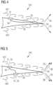
- Figure 4 shows another embodiment of the invention wherein the control unit 33 is omitted.
- the sensor 31 which is arranged at the suction side 27 is directly connected via connection means 34 with the actuator 32.
- connection means may be designed as flexible tubes or channels.
- the effect, namely the generated anti-pressure which is arranged and prepared to at least partly cancelling out the fluctuating surface pressures on the airfoil surface 27 is in principle comparable to the embodiment as illustrated in Figure 3 .
- the input for the actuator 32 only comes from one sensor at the suction side in the embodiment of Figure 4 compared to the embodiment of Figure 3 which implies that the arrangement is more simple, i.e. more robust and more inexpensive, but that it may eliminate slightly less of the noise 35 being generated at the trailing edge 24.
- FIG. 5 illustrates an embodiment of the invention where two membranes, both acting as sensor 31 and actuator 32, are provided. Since trailing edge noise typically radiates to the suction side 27 and the pressure side 28 in anti-phase, such an alternative passive noise cancellation technique may be advantageous.
- the suction side 27 of the airfoil and the pressure side 28 of the airfoil By connecting the suction side 27 of the airfoil and the pressure side 28 of the airfoil, the unsteady surface pressures on the suction side 27 and the pressure side 28 are equalized, however not necessarily to zero.
- the equalized pressure side and suction side fluctuating surface pressures arrive at the trailing edge 24, they both radiate the same sound signal to the pressure side and the suction side, respectively. However, these sound signals are radiated in anti-phase, so that the noise is at least partly cancelled out.
- the membrane position needs to account for the difference and convection speed, on the two sides, the suction side 27 and the pressure side 28 of the airfoil.
Landscapes
- Engineering & Computer Science (AREA)
- Life Sciences & Earth Sciences (AREA)
- Sustainable Development (AREA)
- Sustainable Energy (AREA)
- Chemical & Material Sciences (AREA)
- Combustion & Propulsion (AREA)
- Mechanical Engineering (AREA)
- General Engineering & Computer Science (AREA)
- Wind Motors (AREA)
Claims (5)
- Rotorblatt (20) mit einer Vorderkante (23) und einer Hinterkante (24), das dazu ausgestaltet und ausgelegt ist, einem Fluid ausgesetzt zu werden, das im Wesentlichen von der Vorderkante (23) zur Hinterkante (24) des Rotorblatts (20) strömt, wobei das Rotorblatt (20) einen Abschnitt umfasst, der die Form eines Tragflächenprofils aufweist, umfassend eine Druckseite (28) und eine Saugseite (27), die jeweils durch die Hinterkante und die Vorderkante (23) begrenzt sind, dadurch gekennzeichnet, dass das Rotorblatt (20) umfasst- zwei Membranen (31, 32), die an der Oberfläche des Rotorblatts (20), eine auf der Druckseite und eine auf der Saugseite des Tragflächenprofils, angeordnet und durch ein flexibles Rohr (34) verbunden sind,- wobei jede Membran (31, 32) als ein Sensor (31) zum Detektieren von Strömungseigenschaften des Fluids und als ein Aktuator (32) zum Erzeugen eines geräuschdämpfenden Signals (36) dient,- wobei die Membranen (31, 32) derart angeordnet und ausgebildet sind, dass ein strömungsinduziertes Kantengeräusch (35) des Rotorblatts (20), das durch das Fluid an der Hinterkante (24) des Rotorblatts (20) entsteht, zumindest teilweise durch das geräuschdämpfende Signal (36), das durch die Membranen (31, 32) erzeugt wird, gedämpft wird.
- Rotorblatt (20) nach einem der vorhergehenden Ansprüche, wobei sich die Membran (31, 32) an der Saugseite in Bezug auf die Strömungsrichtung (41) des Fluids stromaufwärts der Membran (31, 32) an der Druckseite befindet.
- Rotorblatt (20) nach einem der vorhergehenden Ansprüche, wobei eine Membran (31, 32) dazu angeordnet und ausgebildet ist, eine zumindest teilweise Dämpfung von instationärer Oberflächendrücke zu induzieren.
- Rotorblatt nach einem der vorhergehenden Ansprüche, wobei die Positione der Membranen (31, 32) unter Berücksichtigung einer Differenz bei einer Konvektionsgeschwindigkeit des Fluids auf der Saugseite (27) und der Druckseite (28) des Tragflächenprofils ausgewählt sind.
- Windenergieanlage mit mindestens einem Rotorblatt (20) nach einem der vorhergehenden Ansprüche.
Priority Applications (5)
| Application Number | Priority Date | Filing Date | Title |
|---|---|---|---|
| PT161716956T PT3249216T (pt) | 2016-05-27 | 2016-05-27 | Pá de rotor com meios de redução de ruído |
| ES16171695T ES2992787T3 (en) | 2016-05-27 | 2016-05-27 | Rotor blade with noise reduction means |
| EP16171695.6A EP3249216B1 (de) | 2016-05-27 | 2016-05-27 | Rotorblatt mit einrichtungen zur geräuschreduzierung |
| US15/587,220 US10502187B2 (en) | 2016-05-27 | 2017-05-04 | Rotor blade with noise reduction means |
| CN201710385267.0A CN107448354B (zh) | 2016-05-27 | 2017-05-26 | 具有降噪机构的转子叶片 |
Applications Claiming Priority (1)
| Application Number | Priority Date | Filing Date | Title |
|---|---|---|---|
| EP16171695.6A EP3249216B1 (de) | 2016-05-27 | 2016-05-27 | Rotorblatt mit einrichtungen zur geräuschreduzierung |
Publications (2)
| Publication Number | Publication Date |
|---|---|
| EP3249216A1 EP3249216A1 (de) | 2017-11-29 |
| EP3249216B1 true EP3249216B1 (de) | 2024-09-18 |
Family
ID=56081396
Family Applications (1)
| Application Number | Title | Priority Date | Filing Date |
|---|---|---|---|
| EP16171695.6A Active EP3249216B1 (de) | 2016-05-27 | 2016-05-27 | Rotorblatt mit einrichtungen zur geräuschreduzierung |
Country Status (5)
| Country | Link |
|---|---|
| US (1) | US10502187B2 (de) |
| EP (1) | EP3249216B1 (de) |
| CN (1) | CN107448354B (de) |
| ES (1) | ES2992787T3 (de) |
| PT (1) | PT3249216T (de) |
Families Citing this family (7)
| Publication number | Priority date | Publication date | Assignee | Title |
|---|---|---|---|---|
| US11408394B2 (en) * | 2018-09-17 | 2022-08-09 | Siemens Gamesa Renewable Energy A/S | Sensor device for an aerodynamic element |
| EP3667081A1 (de) * | 2018-12-13 | 2020-06-17 | Siemens Gamesa Renewable Energy A/S | Windturbinenschaufeldurchflussregulierung |
| DK3812575T3 (da) | 2019-10-23 | 2023-08-21 | Siemens Gamesa Renewable Energy As | Rotorblad med støjreduktionsmidler |
| DK3812576T3 (da) | 2019-10-23 | 2023-07-17 | Siemens Gamesa Renewable Energy As | Rotorblad med støjreduktionsmidler |
| US11384732B2 (en) | 2020-07-13 | 2022-07-12 | Siemens Gamesa Renewable Energy A/S | Noise reduction means for a wind turbine blade, wind turbine blade, wind turbine, and method for noise reduction for a wind turbine blade |
| US11462204B2 (en) | 2020-09-08 | 2022-10-04 | Siemens Gamesa Renewable Energy A/S | Wind turbine and method for noise reduction for a wind turbine |
| US12553413B2 (en) | 2023-01-30 | 2026-02-17 | Siemens Gamesa Renewable Energy A/S | Wind turbine blade and wind turbine |
Citations (1)
| Publication number | Priority date | Publication date | Assignee | Title |
|---|---|---|---|---|
| US20090097976A1 (en) * | 2007-10-15 | 2009-04-16 | General Electric Company | Active damping of wind turbine blades |
Family Cites Families (19)
| Publication number | Priority date | Publication date | Assignee | Title |
|---|---|---|---|---|
| DE4494827D2 (de) | 1993-07-07 | 1996-08-22 | Leistritz Abgastech | Aktiver Schalldämpfer |
| JP2939940B2 (ja) * | 1996-07-09 | 1999-08-25 | 日本電気株式会社 | ファン音消音装置 |
| EP1338793A3 (de) | 2002-02-22 | 2010-09-01 | Mitsubishi Heavy Industries, Ltd. | Gezahnte Windturbinenflügelhinterkante |
| US7688984B2 (en) | 2003-11-26 | 2010-03-30 | The Regents Of The University Of California | Active noise control method and apparatus including feedforward and feedback controllers |
| ES2327696B2 (es) * | 2006-10-11 | 2011-07-28 | GAMESA INNOVATION & TECHNOLOGY, S.L. | Sistema de supresion y anulacion de ruido en aerogeneradores. |
| EP2309119A1 (de) | 2008-08-06 | 2011-04-13 | Mitsubishi Heavy Industries, Ltd. | Windmühlenflügel und ihn verwendender windenergieerzeuger |
| US7896613B2 (en) | 2009-06-03 | 2011-03-01 | General Electric Company | System and method for wind turbine noise control and damage detection |
| US8041540B2 (en) * | 2009-12-09 | 2011-10-18 | General Electric Company | System, device, and method for acoustic and visual monitoring of a wind turbine |
| US8267657B2 (en) | 2010-12-16 | 2012-09-18 | General Electric Company | Noise reducer for rotor blade in wind turbine |
| US20110268558A1 (en) | 2010-12-20 | 2011-11-03 | General Electric Company | Noise reducer for rotor blade in wind turbine |
| US8232663B2 (en) * | 2011-06-30 | 2012-07-31 | General Electric Company | Controlling noise generated by wind turbines in a wind farm by de-synchronization of wind turbine rotors |
| US8430638B2 (en) | 2011-12-19 | 2013-04-30 | General Electric Company | Noise reducer for rotor blade in wind turbine |
| EP2885531B1 (de) * | 2012-08-17 | 2017-03-29 | LM WP Patent Holding A/S | Rotorblattsablenkungsüberwachungssystem |
| CN203163197U (zh) | 2012-10-25 | 2013-08-28 | 宁波奥克斯空调有限公司 | 一种静音空调 |
| US20140142888A1 (en) * | 2012-11-19 | 2014-05-22 | Elwha Llc | Mitigating wind turbine blade noise generation |
| WO2014124643A1 (en) * | 2013-02-14 | 2014-08-21 | Vestas Wind Systems A/S | Detecting blade structure abnormalities |
| US10280896B2 (en) * | 2013-05-24 | 2019-05-07 | Lm Wp Patent Holding A/S | Lightning protection system for a wind turbine blade |
| US20150132130A1 (en) * | 2013-11-12 | 2015-05-14 | NAB & Associates, Inc. | Wind turbine noise and fatigue control |
| US10385826B2 (en) * | 2014-09-12 | 2019-08-20 | Ge Infrastructure Technology, Llc | Wind turbine air deflector system control |
-
2016
- 2016-05-27 EP EP16171695.6A patent/EP3249216B1/de active Active
- 2016-05-27 PT PT161716956T patent/PT3249216T/pt unknown
- 2016-05-27 ES ES16171695T patent/ES2992787T3/es active Active
-
2017
- 2017-05-04 US US15/587,220 patent/US10502187B2/en active Active
- 2017-05-26 CN CN201710385267.0A patent/CN107448354B/zh active Active
Patent Citations (1)
| Publication number | Priority date | Publication date | Assignee | Title |
|---|---|---|---|---|
| US20090097976A1 (en) * | 2007-10-15 | 2009-04-16 | General Electric Company | Active damping of wind turbine blades |
Also Published As
| Publication number | Publication date |
|---|---|
| CN107448354A (zh) | 2017-12-08 |
| PT3249216T (pt) | 2024-11-25 |
| US20170342960A1 (en) | 2017-11-30 |
| ES2992787T3 (en) | 2024-12-18 |
| CN107448354B (zh) | 2020-06-26 |
| EP3249216A1 (de) | 2017-11-29 |
| US10502187B2 (en) | 2019-12-10 |
Similar Documents
| Publication | Publication Date | Title |
|---|---|---|
| US10502187B2 (en) | Rotor blade with noise reduction means | |
| CN103620216B (zh) | 改进的风轮机噪音控制方法 | |
| US20150132130A1 (en) | Wind turbine noise and fatigue control | |
| EP2818702B1 (de) | Aktive Systeme und Verfahren zur Erzeugung von Ultraschallemissionen von Windturbinen | |
| CN111771052B (zh) | 控制风力涡轮机噪声 | |
| ES2901411T3 (es) | Funcionamiento de una turbina eólica | |
| KR102079791B1 (ko) | 풍력 발전 설비의 로터 블레이드 상의 유입을 평가하기 위한 방법, 풍력 발전 설비를 제어하기 위한 방법, 및 풍력 발전 설비 | |
| EP4150209B1 (de) | Windturbinenschaufel mit geräuschminderungsvorrichtung, windturbine und verfahren zur geräuschminderung für eine windturbinenschaufel | |
| US11927175B2 (en) | Rotor blade with noise reduction | |
| US12123398B2 (en) | Rotor blade with noise reduction means | |
| EP2851556A1 (de) | Anordnung zur Minderung des Geräusches eines Windturbinenrotorblatts | |
| US11428207B2 (en) | Wind turbine blade flow regulation | |
| CN112639284B (zh) | 用于风能设备的转子叶片和风能设备 | |
| US12553413B2 (en) | Wind turbine blade and wind turbine | |
| US11536248B2 (en) | Wind power installation |
Legal Events
| Date | Code | Title | Description |
|---|---|---|---|
| PUAI | Public reference made under article 153(3) epc to a published international application that has entered the european phase |
Free format text: ORIGINAL CODE: 0009012 |
|
| STAA | Information on the status of an ep patent application or granted ep patent |
Free format text: STATUS: THE APPLICATION HAS BEEN PUBLISHED |
|
| AK | Designated contracting states |
Kind code of ref document: A1 Designated state(s): AL AT BE BG CH CY CZ DE DK EE ES FI FR GB GR HR HU IE IS IT LI LT LU LV MC MK MT NL NO PL PT RO RS SE SI SK SM TR |
|
| AX | Request for extension of the european patent |
Extension state: BA ME |
|
| STAA | Information on the status of an ep patent application or granted ep patent |
Free format text: STATUS: REQUEST FOR EXAMINATION WAS MADE |
|
| 17P | Request for examination filed |
Effective date: 20180528 |
|
| RBV | Designated contracting states (corrected) |
Designated state(s): AL AT BE BG CH CY CZ DE DK EE ES FI FR GB GR HR HU IE IS IT LI LT LU LV MC MK MT NL NO PL PT RO RS SE SI SK SM TR |
|
| STAA | Information on the status of an ep patent application or granted ep patent |
Free format text: STATUS: EXAMINATION IS IN PROGRESS |
|
| 17Q | First examination report despatched |
Effective date: 20181203 |
|
| RAP1 | Party data changed (applicant data changed or rights of an application transferred) |
Owner name: SIEMENS GAMESA RENEWABLE ENERGY A/S |
|
| GRAP | Despatch of communication of intention to grant a patent |
Free format text: ORIGINAL CODE: EPIDOSNIGR1 |
|
| STAA | Information on the status of an ep patent application or granted ep patent |
Free format text: STATUS: GRANT OF PATENT IS INTENDED |
|
| INTG | Intention to grant announced |
Effective date: 20240314 |
|
| RIN1 | Information on inventor provided before grant (corrected) |
Inventor name: RICHERT, BODO Inventor name: ENEVOLDSEN, PEDER BAY Inventor name: BIRKEMOSE, BO Inventor name: OERLEMANS, STEFAN |
|
| GRAS | Grant fee paid |
Free format text: ORIGINAL CODE: EPIDOSNIGR3 |
|
| GRAA | (expected) grant |
Free format text: ORIGINAL CODE: 0009210 |
|
| STAA | Information on the status of an ep patent application or granted ep patent |
Free format text: STATUS: THE PATENT HAS BEEN GRANTED |
|
| AK | Designated contracting states |
Kind code of ref document: B1 Designated state(s): AL AT BE BG CH CY CZ DE DK EE ES FI FR GB GR HR HU IE IS IT LI LT LU LV MC MK MT NL NO PL PT RO RS SE SI SK SM TR |
|
| REG | Reference to a national code |
Ref country code: GB Ref legal event code: FG4D |
|
| REG | Reference to a national code |
Ref country code: CH Ref legal event code: EP |
|
| REG | Reference to a national code |
Ref country code: IE Ref legal event code: FG4D |
|
| REG | Reference to a national code |
Ref country code: DE Ref legal event code: R096 Ref document number: 602016089428 Country of ref document: DE |
|
| REG | Reference to a national code |
Ref country code: PT Ref legal event code: SC4A Ref document number: 3249216 Country of ref document: PT Date of ref document: 20241125 Kind code of ref document: T Free format text: AVAILABILITY OF NATIONAL TRANSLATION Effective date: 20241118 |
|
| REG | Reference to a national code |
Ref country code: SE Ref legal event code: TRGR |
|
| REG | Reference to a national code |
Ref country code: ES Ref legal event code: FG2A Ref document number: 2992787 Country of ref document: ES Kind code of ref document: T3 Effective date: 20241218 |
|
| REG | Reference to a national code |
Ref country code: LT Ref legal event code: MG9D |
|
| PG25 | Lapsed in a contracting state [announced via postgrant information from national office to epo] |
Ref country code: NO Free format text: LAPSE BECAUSE OF FAILURE TO SUBMIT A TRANSLATION OF THE DESCRIPTION OR TO PAY THE FEE WITHIN THE PRESCRIBED TIME-LIMIT Effective date: 20241218 |
|
| PG25 | Lapsed in a contracting state [announced via postgrant information from national office to epo] |
Ref country code: GR Free format text: LAPSE BECAUSE OF FAILURE TO SUBMIT A TRANSLATION OF THE DESCRIPTION OR TO PAY THE FEE WITHIN THE PRESCRIBED TIME-LIMIT Effective date: 20241219 Ref country code: FI Free format text: LAPSE BECAUSE OF FAILURE TO SUBMIT A TRANSLATION OF THE DESCRIPTION OR TO PAY THE FEE WITHIN THE PRESCRIBED TIME-LIMIT Effective date: 20240918 |
|
| PG25 | Lapsed in a contracting state [announced via postgrant information from national office to epo] |
Ref country code: BG Free format text: LAPSE BECAUSE OF FAILURE TO SUBMIT A TRANSLATION OF THE DESCRIPTION OR TO PAY THE FEE WITHIN THE PRESCRIBED TIME-LIMIT Effective date: 20240918 |
|
| PG25 | Lapsed in a contracting state [announced via postgrant information from national office to epo] |
Ref country code: LV Free format text: LAPSE BECAUSE OF FAILURE TO SUBMIT A TRANSLATION OF THE DESCRIPTION OR TO PAY THE FEE WITHIN THE PRESCRIBED TIME-LIMIT Effective date: 20240918 |
|
| PG25 | Lapsed in a contracting state [announced via postgrant information from national office to epo] |
Ref country code: HR Free format text: LAPSE BECAUSE OF FAILURE TO SUBMIT A TRANSLATION OF THE DESCRIPTION OR TO PAY THE FEE WITHIN THE PRESCRIBED TIME-LIMIT Effective date: 20240918 |
|
| REG | Reference to a national code |
Ref country code: NL Ref legal event code: MP Effective date: 20240918 |
|
| PG25 | Lapsed in a contracting state [announced via postgrant information from national office to epo] |
Ref country code: RS Free format text: LAPSE BECAUSE OF FAILURE TO SUBMIT A TRANSLATION OF THE DESCRIPTION OR TO PAY THE FEE WITHIN THE PRESCRIBED TIME-LIMIT Effective date: 20241218 |
|
| PG25 | Lapsed in a contracting state [announced via postgrant information from national office to epo] |
Ref country code: RS Free format text: LAPSE BECAUSE OF FAILURE TO SUBMIT A TRANSLATION OF THE DESCRIPTION OR TO PAY THE FEE WITHIN THE PRESCRIBED TIME-LIMIT Effective date: 20241218 Ref country code: NO Free format text: LAPSE BECAUSE OF FAILURE TO SUBMIT A TRANSLATION OF THE DESCRIPTION OR TO PAY THE FEE WITHIN THE PRESCRIBED TIME-LIMIT Effective date: 20241218 Ref country code: LV Free format text: LAPSE BECAUSE OF FAILURE TO SUBMIT A TRANSLATION OF THE DESCRIPTION OR TO PAY THE FEE WITHIN THE PRESCRIBED TIME-LIMIT Effective date: 20240918 Ref country code: HR Free format text: LAPSE BECAUSE OF FAILURE TO SUBMIT A TRANSLATION OF THE DESCRIPTION OR TO PAY THE FEE WITHIN THE PRESCRIBED TIME-LIMIT Effective date: 20240918 Ref country code: GR Free format text: LAPSE BECAUSE OF FAILURE TO SUBMIT A TRANSLATION OF THE DESCRIPTION OR TO PAY THE FEE WITHIN THE PRESCRIBED TIME-LIMIT Effective date: 20241219 Ref country code: FI Free format text: LAPSE BECAUSE OF FAILURE TO SUBMIT A TRANSLATION OF THE DESCRIPTION OR TO PAY THE FEE WITHIN THE PRESCRIBED TIME-LIMIT Effective date: 20240918 Ref country code: BG Free format text: LAPSE BECAUSE OF FAILURE TO SUBMIT A TRANSLATION OF THE DESCRIPTION OR TO PAY THE FEE WITHIN THE PRESCRIBED TIME-LIMIT Effective date: 20240918 |
|
| REG | Reference to a national code |
Ref country code: AT Ref legal event code: MK05 Ref document number: 1724878 Country of ref document: AT Kind code of ref document: T Effective date: 20240918 |
|
| PG25 | Lapsed in a contracting state [announced via postgrant information from national office to epo] |
Ref country code: NL Free format text: LAPSE BECAUSE OF FAILURE TO SUBMIT A TRANSLATION OF THE DESCRIPTION OR TO PAY THE FEE WITHIN THE PRESCRIBED TIME-LIMIT Effective date: 20240918 |
|
| PG25 | Lapsed in a contracting state [announced via postgrant information from national office to epo] |
Ref country code: IS Free format text: LAPSE BECAUSE OF FAILURE TO SUBMIT A TRANSLATION OF THE DESCRIPTION OR TO PAY THE FEE WITHIN THE PRESCRIBED TIME-LIMIT Effective date: 20250118 |
|
| PG25 | Lapsed in a contracting state [announced via postgrant information from national office to epo] |
Ref country code: RO Free format text: LAPSE BECAUSE OF FAILURE TO SUBMIT A TRANSLATION OF THE DESCRIPTION OR TO PAY THE FEE WITHIN THE PRESCRIBED TIME-LIMIT Effective date: 20240918 Ref country code: SM Free format text: LAPSE BECAUSE OF FAILURE TO SUBMIT A TRANSLATION OF THE DESCRIPTION OR TO PAY THE FEE WITHIN THE PRESCRIBED TIME-LIMIT Effective date: 20240918 |
|
| PG25 | Lapsed in a contracting state [announced via postgrant information from national office to epo] |
Ref country code: EE Free format text: LAPSE BECAUSE OF FAILURE TO SUBMIT A TRANSLATION OF THE DESCRIPTION OR TO PAY THE FEE WITHIN THE PRESCRIBED TIME-LIMIT Effective date: 20240918 Ref country code: AT Free format text: LAPSE BECAUSE OF FAILURE TO SUBMIT A TRANSLATION OF THE DESCRIPTION OR TO PAY THE FEE WITHIN THE PRESCRIBED TIME-LIMIT Effective date: 20240918 |
|
| PG25 | Lapsed in a contracting state [announced via postgrant information from national office to epo] |
Ref country code: CZ Free format text: LAPSE BECAUSE OF FAILURE TO SUBMIT A TRANSLATION OF THE DESCRIPTION OR TO PAY THE FEE WITHIN THE PRESCRIBED TIME-LIMIT Effective date: 20240918 Ref country code: PL Free format text: LAPSE BECAUSE OF FAILURE TO SUBMIT A TRANSLATION OF THE DESCRIPTION OR TO PAY THE FEE WITHIN THE PRESCRIBED TIME-LIMIT Effective date: 20240918 |
|
| PG25 | Lapsed in a contracting state [announced via postgrant information from national office to epo] |
Ref country code: IT Free format text: LAPSE BECAUSE OF FAILURE TO SUBMIT A TRANSLATION OF THE DESCRIPTION OR TO PAY THE FEE WITHIN THE PRESCRIBED TIME-LIMIT Effective date: 20240918 Ref country code: SK Free format text: LAPSE BECAUSE OF FAILURE TO SUBMIT A TRANSLATION OF THE DESCRIPTION OR TO PAY THE FEE WITHIN THE PRESCRIBED TIME-LIMIT Effective date: 20240918 |
|
| REG | Reference to a national code |
Ref country code: DE Ref legal event code: R097 Ref document number: 602016089428 Country of ref document: DE |
|
| PGFP | Annual fee paid to national office [announced via postgrant information from national office to epo] |
Ref country code: DE Payment date: 20250528 Year of fee payment: 10 |
|
| PG25 | Lapsed in a contracting state [announced via postgrant information from national office to epo] |
Ref country code: DK Free format text: LAPSE BECAUSE OF FAILURE TO SUBMIT A TRANSLATION OF THE DESCRIPTION OR TO PAY THE FEE WITHIN THE PRESCRIBED TIME-LIMIT Effective date: 20240918 |
|
| PGFP | Annual fee paid to national office [announced via postgrant information from national office to epo] |
Ref country code: ES Payment date: 20250612 Year of fee payment: 10 |
|
| PGFP | Annual fee paid to national office [announced via postgrant information from national office to epo] |
Ref country code: PT Payment date: 20250506 Year of fee payment: 10 |
|
| PLBE | No opposition filed within time limit |
Free format text: ORIGINAL CODE: 0009261 |
|
| STAA | Information on the status of an ep patent application or granted ep patent |
Free format text: STATUS: NO OPPOSITION FILED WITHIN TIME LIMIT |
|
| PGFP | Annual fee paid to national office [announced via postgrant information from national office to epo] |
Ref country code: SE Payment date: 20250526 Year of fee payment: 10 |
|
| 26N | No opposition filed |
Effective date: 20250619 |
|
| REG | Reference to a national code |
Ref country code: CH Ref legal event code: H13 Free format text: ST27 STATUS EVENT CODE: U-0-0-H10-H13 (AS PROVIDED BY THE NATIONAL OFFICE) Effective date: 20251223 |
|
| PG25 | Lapsed in a contracting state [announced via postgrant information from national office to epo] |
Ref country code: LU Free format text: LAPSE BECAUSE OF NON-PAYMENT OF DUE FEES Effective date: 20250527 |
|
| PG25 | Lapsed in a contracting state [announced via postgrant information from national office to epo] |
Ref country code: CH Free format text: LAPSE BECAUSE OF NON-PAYMENT OF DUE FEES Effective date: 20250531 |
|
| REG | Reference to a national code |
Ref country code: BE Ref legal event code: MM Effective date: 20250531 |
|
| PG25 | Lapsed in a contracting state [announced via postgrant information from national office to epo] |
Ref country code: MC Free format text: LAPSE BECAUSE OF FAILURE TO SUBMIT A TRANSLATION OF THE DESCRIPTION OR TO PAY THE FEE WITHIN THE PRESCRIBED TIME-LIMIT Effective date: 20240918 |
|
| PGFP | Annual fee paid to national office [announced via postgrant information from national office to epo] |
Ref country code: GB Payment date: 20260323 Year of fee payment: 11 |
|
| PG25 | Lapsed in a contracting state [announced via postgrant information from national office to epo] |
Ref country code: IE Free format text: LAPSE BECAUSE OF NON-PAYMENT OF DUE FEES Effective date: 20250527 |
|
| PG25 | Lapsed in a contracting state [announced via postgrant information from national office to epo] |
Ref country code: BE Free format text: LAPSE BECAUSE OF NON-PAYMENT OF DUE FEES Effective date: 20250531 |
|
| PG25 | Lapsed in a contracting state [announced via postgrant information from national office to epo] |
Ref country code: FR Free format text: LAPSE BECAUSE OF NON-PAYMENT OF DUE FEES Effective date: 20250531 |