EP3249236A1 - Extraction de fumée - Google Patents
Extraction de fumée Download PDFInfo
- Publication number
- EP3249236A1 EP3249236A1 EP17170911.6A EP17170911A EP3249236A1 EP 3249236 A1 EP3249236 A1 EP 3249236A1 EP 17170911 A EP17170911 A EP 17170911A EP 3249236 A1 EP3249236 A1 EP 3249236A1
- Authority
- EP
- European Patent Office
- Prior art keywords
- pump
- flow rate
- data
- speed
- data processor
- Prior art date
- Legal status (The legal status is an assumption and is not a legal conclusion. Google has not performed a legal analysis and makes no representation as to the accuracy of the status listed.)
- Withdrawn
Links
- 238000000605 extraction Methods 0.000 title claims abstract description 53
- 239000003517 fume Substances 0.000 title claims abstract description 33
- 238000005259 measurement Methods 0.000 claims abstract description 5
- 238000000034 method Methods 0.000 claims description 26
- 206010019233 Headaches Diseases 0.000 description 29
- 230000007423 decrease Effects 0.000 description 9
- 238000009434 installation Methods 0.000 description 5
- 238000011045 prefiltration Methods 0.000 description 5
- OKTJSMMVPCPJKN-UHFFFAOYSA-N Carbon Chemical compound [C] OKTJSMMVPCPJKN-UHFFFAOYSA-N 0.000 description 4
- 239000007789 gas Substances 0.000 description 4
- 238000012545 processing Methods 0.000 description 4
- 238000004364 calculation method Methods 0.000 description 3
- 238000004519 manufacturing process Methods 0.000 description 3
- 239000002245 particle Substances 0.000 description 3
- 239000000356 contaminant Substances 0.000 description 2
- 238000012937 correction Methods 0.000 description 2
- 238000009825 accumulation Methods 0.000 description 1
- 230000000903 blocking effect Effects 0.000 description 1
- 238000009530 blood pressure measurement Methods 0.000 description 1
- 238000010586 diagram Methods 0.000 description 1
- 239000003814 drug Substances 0.000 description 1
- 230000009977 dual effect Effects 0.000 description 1
- 230000008713 feedback mechanism Effects 0.000 description 1
- 231100001261 hazardous Toxicity 0.000 description 1
- 238000003698 laser cutting Methods 0.000 description 1
- 238000010147 laser engraving Methods 0.000 description 1
- 238000010330 laser marking Methods 0.000 description 1
- 238000012806 monitoring device Methods 0.000 description 1
- 238000012544 monitoring process Methods 0.000 description 1
- 229920006395 saturated elastomer Polymers 0.000 description 1
- 238000012360 testing method Methods 0.000 description 1
- 238000011144 upstream manufacturing Methods 0.000 description 1
Images


Classifications
-
- F—MECHANICAL ENGINEERING; LIGHTING; HEATING; WEAPONS; BLASTING
- F04—POSITIVE - DISPLACEMENT MACHINES FOR LIQUIDS; PUMPS FOR LIQUIDS OR ELASTIC FLUIDS
- F04D—NON-POSITIVE-DISPLACEMENT PUMPS
- F04D15/00—Control, e.g. regulation, of pumps, pumping installations or systems
- F04D15/0066—Control, e.g. regulation, of pumps, pumping installations or systems by changing the speed, e.g. of the driving engine
-
- B—PERFORMING OPERATIONS; TRANSPORTING
- B08—CLEANING
- B08B—CLEANING IN GENERAL; PREVENTION OF FOULING IN GENERAL
- B08B15/00—Preventing escape of dirt or fumes from the area where they are produced; Collecting or removing dirt or fumes from that area
-
- B—PERFORMING OPERATIONS; TRANSPORTING
- B01—PHYSICAL OR CHEMICAL PROCESSES OR APPARATUS IN GENERAL
- B01D—SEPARATION
- B01D46/00—Filters or filtering processes specially modified for separating dispersed particles from gases or vapours
- B01D46/42—Auxiliary equipment or operation thereof
- B01D46/44—Auxiliary equipment or operation thereof controlling filtration
- B01D46/444—Auxiliary equipment or operation thereof controlling filtration by flow measuring
-
- B—PERFORMING OPERATIONS; TRANSPORTING
- B01—PHYSICAL OR CHEMICAL PROCESSES OR APPARATUS IN GENERAL
- B01D—SEPARATION
- B01D46/00—Filters or filtering processes specially modified for separating dispersed particles from gases or vapours
- B01D46/42—Auxiliary equipment or operation thereof
- B01D46/44—Auxiliary equipment or operation thereof controlling filtration
- B01D46/446—Auxiliary equipment or operation thereof controlling filtration by pressure measuring
-
- B—PERFORMING OPERATIONS; TRANSPORTING
- B08—CLEANING
- B08B—CLEANING IN GENERAL; PREVENTION OF FOULING IN GENERAL
- B08B15/00—Preventing escape of dirt or fumes from the area where they are produced; Collecting or removing dirt or fumes from that area
- B08B15/002—Preventing escape of dirt or fumes from the area where they are produced; Collecting or removing dirt or fumes from that area using a central suction system, e.g. for collecting exhaust gases in workshops
-
- B—PERFORMING OPERATIONS; TRANSPORTING
- B08—CLEANING
- B08B—CLEANING IN GENERAL; PREVENTION OF FOULING IN GENERAL
- B08B15/00—Preventing escape of dirt or fumes from the area where they are produced; Collecting or removing dirt or fumes from that area
- B08B15/02—Preventing escape of dirt or fumes from the area where they are produced; Collecting or removing dirt or fumes from that area using chambers or hoods covering the area
-
- F—MECHANICAL ENGINEERING; LIGHTING; HEATING; WEAPONS; BLASTING
- F04—POSITIVE - DISPLACEMENT MACHINES FOR LIQUIDS; PUMPS FOR LIQUIDS OR ELASTIC FLUIDS
- F04D—NON-POSITIVE-DISPLACEMENT PUMPS
- F04D15/00—Control, e.g. regulation, of pumps, pumping installations or systems
- F04D15/0077—Safety measures
-
- F—MECHANICAL ENGINEERING; LIGHTING; HEATING; WEAPONS; BLASTING
- F04—POSITIVE - DISPLACEMENT MACHINES FOR LIQUIDS; PUMPS FOR LIQUIDS OR ELASTIC FLUIDS
- F04D—NON-POSITIVE-DISPLACEMENT PUMPS
- F04D27/00—Control, e.g. regulation, of pumps, pumping installations or pumping systems specially adapted for elastic fluids
- F04D27/001—Testing thereof; Determination or simulation of flow characteristics; Stall or surge detection, e.g. condition monitoring
-
- F—MECHANICAL ENGINEERING; LIGHTING; HEATING; WEAPONS; BLASTING
- F04—POSITIVE - DISPLACEMENT MACHINES FOR LIQUIDS; PUMPS FOR LIQUIDS OR ELASTIC FLUIDS
- F04D—NON-POSITIVE-DISPLACEMENT PUMPS
- F04D27/00—Control, e.g. regulation, of pumps, pumping installations or pumping systems specially adapted for elastic fluids
- F04D27/004—Control, e.g. regulation, of pumps, pumping installations or pumping systems specially adapted for elastic fluids by varying driving speed
-
- G—PHYSICS
- G05—CONTROLLING; REGULATING
- G05B—CONTROL OR REGULATING SYSTEMS IN GENERAL; FUNCTIONAL ELEMENTS OF SUCH SYSTEMS; MONITORING OR TESTING ARRANGEMENTS FOR SUCH SYSTEMS OR ELEMENTS
- G05B15/00—Systems controlled by a computer
- G05B15/02—Systems controlled by a computer electric
-
- G—PHYSICS
- G05—CONTROLLING; REGULATING
- G05D—SYSTEMS FOR CONTROLLING OR REGULATING NON-ELECTRIC VARIABLES
- G05D7/00—Control of flow
- G05D7/06—Control of flow characterised by the use of electric means
- G05D7/0617—Control of flow characterised by the use of electric means specially adapted for fluid materials
- G05D7/0623—Control of flow characterised by the use of electric means specially adapted for fluid materials characterised by the set value given to the control element
-
- Y—GENERAL TAGGING OF NEW TECHNOLOGICAL DEVELOPMENTS; GENERAL TAGGING OF CROSS-SECTIONAL TECHNOLOGIES SPANNING OVER SEVERAL SECTIONS OF THE IPC; TECHNICAL SUBJECTS COVERED BY FORMER USPC CROSS-REFERENCE ART COLLECTIONS [XRACs] AND DIGESTS
- Y02—TECHNOLOGIES OR APPLICATIONS FOR MITIGATION OR ADAPTATION AGAINST CLIMATE CHANGE
- Y02B—CLIMATE CHANGE MITIGATION TECHNOLOGIES RELATED TO BUILDINGS, e.g. HOUSING, HOUSE APPLIANCES OR RELATED END-USER APPLICATIONS
- Y02B30/00—Energy efficient heating, ventilation or air conditioning [HVAC]
- Y02B30/70—Efficient control or regulation technologies, e.g. for control of refrigerant flow, motor or heating
Definitions
- the present invention relates generally to fume extraction.
- extraction systems are used to capture hazardous particulate and gaseous and vaporised matter generated by industrial processes.
- Known fume extraction systems comprise filter units, such as multiple graded particle filters and a gas filter (typically activated carbon-based) which are housed in a single unit, together with an extraction pump.
- the extraction pump draws contaminated air into the unit, through the filters to remove the contaminants and outputs filtered air to the working area.
- Fume extraction units When saturated, the filters, and in particular the gas filter, must be replaced. In environments where high rates of gas and vapours are generated, the filters will need to be replaced more often.
- Fume extraction units usually incorporate a centrifugal suction pump. The suction creates an airflow which removes unwanted particles from an area.
- the fume extraction units usually provide a means of controlling the airflow rate. There are three methods currently used by fume extraction units, namely, pump voltage control, inlet pressure control and Pitot tube airflow.
- the extraction unit's centrifugal pump has a drive voltage input.
- the pump's speed is relative to the input driver voltage and pressure.
- the extraction unit provides a means of allowing the user to control the drive voltage to the pump, in turn controlling the extraction unit.
- Fume extraction units may incorporate two HEPA filters which gradually increase in air restriction as they become blocked. To maintain the desired airflow the user would have to manually increase voltage to the pump as the filters become blocked.
- a resistive potentiometer can be used to adjust a drive voltage fed to the pump.
- the inlet pressure control method uses the unit's inlet differential pressure reading as a control variable in a feedback control loop.
- the fume extraction unit incorporates an electronic control system.
- the system monitors the differential pressure between the inlet and atmosphere (gauge pressure).
- the control system uses the inlet differential pressure reading as a feedback parameter in a motor control algorithm, and, usually as a PI (Proportional Integral) or PID (Proportional Integral Differential) control loop.
- a proportional-integral-derivative controller is a control loop feedback mechanism (controller) commonly used in industrial control systems.
- a PID controller continuously calculates an error value as the difference between a desired set-point and a measured process variable. The controller attempts to minimize the error over time by adjustment of a control variable.
- This method allows the user to set the desired speed of the motor to achieve the desired airflow.
- the actual airflow is not known by the system.
- the control system will record the inlet differential pressure and attempt to maintain its value, in turn maintaining the desired airflow.
- the control loop incorporated into the inlet pressure control method increases the pump drive voltage for a decrease in inlet differential pressure and decreases pump drive voltage for an increase in inlet differential pressure.
- This method will maintain the desired airflow as the system's filters progressively block. As the filters block the airflow will reduce, in turn reducing the inlet differential pressure.
- the control system will determine this and responds by increasing the pump's drive voltage until the inlet differential pressure is at the recorded value, in turn maintaining the desired airflow. When a blocked filter is replaced with a new filter the airflow will increase, the control system will see an increase in inlet differential pressure and decrease the pump drive voltage accordingly.
- a disadvantage with this method is that the desired airflow will not be maintained for changes in customer installation.
- the example is given of a blockage occurring in the interconnecting ducting between the customer's installed equipment and the inlet.
- An increase in the customer installations restriction would cause the pressure to increase and the airflow to decrease this increasing pressure will cause the control system to decrease the pump drive voltage until recording inlet pressure is met. This will cause the airflow to further decrease.
- the inlet differential pressure will be maintained but the desired airflow will not.
- An increase in customer installation restriction will cause the system's airflow to reduce, a decrease in customer installation restriction will cause the system's airflow to increase.
- the desired airflow will only be met with this method if the customer's installation restriction remains constant after the desired airflow has been set.
- the Pitot tube method requires an instrument which is used to measure the velocity of moving air.
- a fume extraction unit that includes a Pitot tube can determine the air flow rate of the system.
- the volume of moving air needs to be known. Placing a Pitot tube in a duct which all the system's air moves through allows this to be calculated.
- the disadvantages of calculating airflow in this way are that a Pitot tube and a Pitot tube housing is required, which restricts the available flow area for air flowing through the system.
- a fume extraction apparatus which comprises an extraction pump, the apparatus further comprising a sensor arrangement to measure a differential pressure across the pump and to measure a rotational speed of the extraction pump, and the apparatus comprising a controller which comprises a data processor, the data processor arranged to calculate a flow rate of air through the apparatus using the measurements from the sensor arrangement, and to compare the calculated flow rate to a target flow rate, and the controller arranged to issue a control signal to control the rotational speed of the pump so as to better align the flow rate with the target flow rate.
- the control signal may be termed a correction signal.
- the data processor may be arranged to determine the flow rate using a relationship between operational parameters such as flow rate, differential pressure and pump speed.
- the relationship may be stored as a data set and/or in analytical form, such as by one or more equations, or mathematical statements, of a relationship between variables/operational parameters.
- the controller may comprise a memory which stores data representative of a relationship between pressure, flow rate and rotational pump speed.
- the data may include a number of data sets, each representative of values of particular operational parameters, such as the relationship between pressure and flow rate for a number of rotational pump speeds.
- the data may comprise a set of discrete data points.
- the data may be viewed as being characteristic of the operational performance of the pump.
- the data may be stored in the form of a look-up table. The data may be viewed or considered as idealised or reference data.
- the data processor may be configured to use one or a combination of the data set and the mathematical relationships.
- the data processor is operative to use this value of flow rate is used.
- the data processor is arranged to employ at least one known set of values of flow rate pressure for a given rotational speed, together with a mathematical relationship between the variables at different operational conditions, to determine the flow rate at the measured speed using the known data and the mathematical relationship.
- the mathematical relationship comprises at least one of:
- the data processor may be configured to calculate the pump's differential pressure at a speed for which a reference data set is available, and to use an equation above to calculate said differential pressure, using the speed, the measured speed and the measured pressure differential.
- the data processor may be further configured to determine the pump's flow rate using the calculated pressure differential and referring to the data set.
- the data processor may be configured to calculate the flow rate at the measured pump speed using the equations above, and based on the calculated flow rate, the measured speed and the data set reference speed.
- Two or more data sets, each corresponding to a particular pump speed may be employed in determining a flow rate of a measured speed. Where two data sets are used, each corresponding to a particular pump speed, a weighted average of the calculated flow rates (for the measured speed) is used to determine the calculated flow rate. The weighted average may be based on the relative difference in speed value between each reference value and the measured value. The measured speed value is preferably intermediate of the two reference speed values.
- the data processor may be arranged to interpolate between data set points in order to determine a prevailing flow rate through the pump.
- the controller may be incorporated (integrally) with a (main) housing of the extractor, or, alternatively, may be separate from the extractor but connected by way of a communications connection. It will be appreciated that the controller, or least a data processor which is configured to process measured parameters, need not necessarily be located or reside within a housing of the extraction unit. For example, the data processor may be a distinct separate unit which is connected to the extraction unit by way of cabling or wiring.
- the sensor arrangement may comprise a differential pressure sensor to measure the pressure differential across the pump.
- the differential pressure across the pump and in particular the difference between the prevailing air pressure at an inlet to the pump and that at an outlet to the pump, may be termed the head pressure.
- the sensor arrangement may comprise a tachometer to measure the rotational speed of the pump.
- the data processor may be arranged to determine a new rotational speed of the pump based on a differential between the calculated flow rate and the target flow rate.
- the processor need not necessarily attempt to determine a new rotational speed as such.
- the controller uses the flow and target flow as inputs into a suitable PID (or PI) algorithm or sequence of processing steps.
- the PID algorithm may calculate the drive voltage to the pump based on the error (magnitude) between the calculated flow and the target flow.
- the PID algorithm may not have knowledge of the pump's speed.
- the PID algorithm may calculate the rate at which the pump's drive voltage needs to change to maintain or reach the target flow. This in turn controls the pump's rotational speed accordingly.
- the data processor may be arranged to determine an outlet gauge pressure, namely which comprises the sum of the measured head pressure and the system vacuum pressure.
- the data processor may be arranged to be capable of calculating a measure of power consumption by the pump.
- the data processor may be arranged to calculate the power consumption of the pump by using an affinity equation.
- the data processor may be arranged to be capable of determining the operational efficiency of the pump.
- a method of determining flow rate in a fume extraction apparatus comprising measuring a differential pressure across a suction pump of the apparatus, and measuring a rotational speed of the suction pump, the method further comprises comparing the calculated flow rate with a target flow rate, and issuing a control signal to control the pump speed to better align the flow rate with the target flow rate.
- the apparatus or the method may include one or more features as described in the description and/or as shown in the drawings, either individually or in combination.
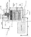
- the fume extraction unit 1 comprises at least one graded particle filter (referred to as a pre-filter 2) and a gas filter (typically activated carbon-based, and referred to as a combined filter 3) which are housed in a single unit 4, together with an extraction pump 6.
- the extraction pump draws contaminated air into the unit, through an inlet 7, through the filters 2 and 3 to remove the contaminants and then output filtered air to the working area.
- the unit 1 further comprises a controller 10 comprising a data processor and a memory, which is connected to various sensors, and is arranged to perform various processing tasks, which includes providing a control signal to control the rotational speed of the pump 6.
- a controller 10 comprising a data processor and a memory, which is connected to various sensors, and is arranged to perform various processing tasks, which includes providing a control signal to control the rotational speed of the pump 6.
- the unit 1 yet further comprises a sensor array, which comprises a pump differential sensor, indicated at 12a and 12b, and essentially comprises a differential pressure sensor with its sensing inlet points located at 12a and 12b, and thereby measures the differential pressure across the outlet and the inlet (respectively).
- the sensor arrangement further comprises a pressure sensor 13 which is located at the outlet (or immediately downstream) of the pre-filter 2 and a pressure sensor 14 which is located at the inlet (or immediately upstream of) the pre-filter 2.
- the sensor arrangement comprises a tachometer (unreferenced) which monitors the rotational speed of the pump.
- FIG. 5 shows an example how the (differential) pressure sensors could be implemented.
- four differential pressure sensors are used.
- Each sensor (arrangement) determines the difference in pressure between two pressure measurement points. This may be realised by way of a dual inlet device or manifold 20 connected by tubing to the measurement points, for each sensor inlet.
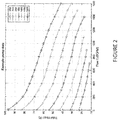
- the memory of the controller 10 is arranged to store predetermined pump curve data, as shown for example in Figure 2 .
- This data will serve as reference data which will be used in determining flow rate at a measured rotational speed of the pump. The way that this stored data is used will be described in more details below.
- the suction pump 6 comprises a centrifugal suction pump.
- This type of pump is subject to a set of relationships between the variables, sometimes referred to as affinity laws. These express the mathematical relationship between the operational parameters of head pressure, volumetric flow rate, power usage and shaft speed of a centrifugal pump. These can be expressed in the following equations (for fixed impeller diameter):
- these relationships will be used to calculate the change in one variable for a change in another. For example, if the speed, head pressure and flow are known, then the head pressure and flow of the pump could be calculated for a change in speed.
- the controller 10 incorporates a processing routine which calculates the system's airflow using the pump's measured head pressure and measured speed, along with predetermined pump reference/performance datasets which are stored in the memory, and interpolation.
- the calculated flow value is then used as a feedback parameter in a PI or PID motor control algorithm. This then allows the control system to maintain the desired target airflow. If the pump's measured speed is equal to a predetermined value in the stored dataset, then the airflow rate can be determined directly from the data. Alternatively, if the pumps measured speed lies in between two predetermined data set speeds, then the airflow can be calculated using a combination of the mathematical relationships and interpolation.
- calculating the pump's current flow requirements includes performing the following steps:
- the pump's current rotational speed and its current head pressure are measured by the respective sensors.
- speed 1050 rpm
- measured head pressure 50 ft.
- the data processor is configured to calculate the pump's expected head pressure at the speed of the stored data set at 1200 rpm.
- the data processor is then configured to refer to the stored data set using the just calculated head pressure value to determine the corresponding expected flow at 1200 rpm. In this example, this is equal to 785 USGPM (US Gallons Per Minute).
- the data processor is able to determine the flow rate at 1050 rpm, namely, in this case, 687 USGPM. This is shown in Figure 3 .
- the data processor having now calculated the current flow rate can then compare this value to the set target flow rate which is stored in the memory.
- the data processor is configured to output a control or correction signal to the pump which is operative to control the rotational speed of the pump with the objective of bringing the actual flow rate to the target rate.
- a PID or PI algorithm is used by the data processor to use flow and target flow as parameters in a feedback control loop (PID, PI).
- the PID algorithm calculates a measure of the required pump drive voltage (to maintain or reach or better align) with the target flow.
- the data processor is first configured to use the equations referred above to calculate the expected head pressures on each of the reference data lines at 1000 and 1100 rpm respectively.
- the equations referred to above can again be used by the data processor to calculate the expected flow rate at the current pump speed using in turn, each of the data lines.
- the calculated flows for each of the data set reference speeds are as follows:
- the above calculated data can then be used for the data processor to calculate a final flow at the measured current speed.
- This final flow calculation includes determining a weighted average which is proportional to how close the current speed is to the two chosen data-line speeds. This skews the result in favour of the stored data line which is closest to the measured current pump speed. In this current example, the current speed lies exactly between the adjacent line speeds, and therefore the calculated flow will be the average of both results.
- the above described fume extraction apparatus represents a novel and advantageous manner of determining and controlling flow rate.
- the advantages include:
- the differential pressure across the extraction pump may be determined by the data processor in a different manner.
- This method involves obtaining the head pressure indirectly by monitoring the pressures on each side of the pump and then using these measured values to calculate the head pressure.
- the pumps head pressure can be calculated by calculating the system vacuum which is the sum of the pressure across the combined filter, the pressure across the pre-filter and the pressure across the inlet from which is then deducted the outlet pressure. In this manner of determining the differential pressure in combination with other sensors and not directly with each other to determine the pressure value.
- the above apparatus can also be used within systems that use several pumps in parallel to provide higher flow rates.
- average head pressure across all pumps can be monitored using a single differential pressure sensor, by the controller.
- One of two methods can then be used to obtain the pump speeds, either average speed or individual speed determination.
- the average speed of the connected pumps is calculated and used to then calculate the overall flow of the system.
- the same type of pump will be used within a single system.
- Each pump is driven by the same drive voltage and the speeds of the pumps should be very close to each other.
- the speed of each pump will be obtained independently.
- the independent speeds will be used to calculate the flows of each pump.
- the system flow will be calculated as the accumulation or sum of the calculated independent flows.
- the controller is also configured to be capable of determining the pump's input power (W).
- W pump's input power
- This power data could be collected during a test/calibration phase.
- the running power usage is calculated from this obtained data only, and no power monitoring device is installed within the unit during operation. This allows the unit power usage to be monitored.
- the data processor is capable of calculating the running power usage of the system. Calculating the unit's power usage allows the running costs of the system to be calculated. This in turn allows the most cost effective time to replace filters to be determined. In known fume extraction controllers when a filter is determined by the controller to be blocked, the user is notified when the target air flow cannot be reached.
- This method provides the user with the longest possible filter life at the systems target flow. Although this method increases filter life it may be not the most cost effective solution. Towards the end of a filter's life its air restriction increases. The increased air restriction means that the pump has to work harder to achieve the target air flow, increasing the cost of running the unit.
- the calculated running cost of the unit can be used to determine the most cost effective time to replace a filter, taking account of power cost, filter cost (in terms of unit price and delivery cost).
- account can also be taken of location stock levels and stock space. It will be possible to determine the most cost effective filter replacement schedule taking into account reduced delivery cost for bulk delivery.
- the apparatus 1 can also advantageously be used to obtain an outlet 'gauge' pressure reading.
- This is the system vacuum plus the head pressure.
- the system vacuum is the sum of the combined differential pressure, the Pre-Filter differential pressure and the inlet differential pressure.
- the data processor can therefore readily determine the outlet gauge pressure. This allows the controller to monitor the complete system's pressure usage without the addition of a dedicated differential pressure sensor for the purpose of measuring the outlet differential pressure.
Landscapes
- Engineering & Computer Science (AREA)
- General Engineering & Computer Science (AREA)
- Mechanical Engineering (AREA)
- Physics & Mathematics (AREA)
- General Physics & Mathematics (AREA)
- Automation & Control Theory (AREA)
- Chemical & Material Sciences (AREA)
- Chemical Kinetics & Catalysis (AREA)
- Measuring Volume Flow (AREA)
- Flow Control (AREA)
- Control Of Positive-Displacement Pumps (AREA)
Applications Claiming Priority (1)
| Application Number | Priority Date | Filing Date | Title |
|---|---|---|---|
| GB1609111.8A GB2550598A (en) | 2016-05-24 | 2016-05-24 | Fume extraction |
Publications (1)
| Publication Number | Publication Date |
|---|---|
| EP3249236A1 true EP3249236A1 (fr) | 2017-11-29 |
Family
ID=56369874
Family Applications (1)
| Application Number | Title | Priority Date | Filing Date |
|---|---|---|---|
| EP17170911.6A Withdrawn EP3249236A1 (fr) | 2016-05-24 | 2017-05-12 | Extraction de fumée |
Country Status (3)
| Country | Link |
|---|---|
| US (1) | US20170350400A1 (fr) |
| EP (1) | EP3249236A1 (fr) |
| GB (1) | GB2550598A (fr) |
Cited By (5)
| Publication number | Priority date | Publication date | Assignee | Title |
|---|---|---|---|---|
| CN108089470A (zh) * | 2018-02-11 | 2018-05-29 | 上海联达节能科技股份有限公司 | 一种除尘风机控制系统及除尘系统的改造方法 |
| CN108361216A (zh) * | 2018-02-11 | 2018-08-03 | 上海联达节能科技股份有限公司 | 一种除尘风机多参量控制系统及除尘系统的改造方法 |
| CN108374797A (zh) * | 2018-02-11 | 2018-08-07 | 上海联达节能科技股份有限公司 | 一种除尘风机联动控制系统及除尘系统的改造方法 |
| FR3098753A1 (fr) * | 2019-07-18 | 2021-01-22 | A3D L'atelier Numerique | dispositif de filtration destiné aux imprimantes 3D, quelles que soient leur taille ou leur technologie, pour remédier aux inconvénients de diffusion de pollutions |
| GB2625356A (en) * | 2022-12-15 | 2024-06-19 | D2 Embedded Solutions Ltd | Method of controlling fan systems |
Families Citing this family (4)
| Publication number | Priority date | Publication date | Assignee | Title |
|---|---|---|---|---|
| JP7236436B2 (ja) * | 2018-03-20 | 2023-03-09 | テルモ株式会社 | 計測システムおよび計算ユニット |
| EP3569865A1 (fr) * | 2018-05-15 | 2019-11-20 | Siemens Aktiengesellschaft | Surveillance d'une pompe centrifuge entrainée par un moteur électrique |
| EP3599037A1 (fr) * | 2018-07-25 | 2020-01-29 | Primetals Technologies Germany GmbH | Section de refroidissement à réglage de flux de liquide de refroidissement à l'aide des pompes |
| CN119136891A (zh) * | 2022-04-29 | 2024-12-13 | 唐纳森公司 | 空气过滤监测系统 |
Citations (4)
| Publication number | Priority date | Publication date | Assignee | Title |
|---|---|---|---|---|
| US5586861A (en) * | 1993-05-17 | 1996-12-24 | Pace Company | Airflow measuring centrifugal fan |
| US6186744B1 (en) * | 1996-10-12 | 2001-02-13 | Synetics Solutions Inc. | Volumetric airflow indicator and control device |
| US20080188173A1 (en) * | 2007-02-06 | 2008-08-07 | Nordyne, Inc. | Ventilation airflow rate control |
| US20140133999A1 (en) * | 2012-11-13 | 2014-05-15 | Zhongshan Broad-Ocean Motor Co., Ltd. | Method for controlling air volume |
Family Cites Families (4)
| Publication number | Priority date | Publication date | Assignee | Title |
|---|---|---|---|---|
| US4108574A (en) * | 1977-01-21 | 1978-08-22 | International Paper Company | Apparatus and method for the indirect measurement and control of the flow rate of a liquid in a piping system |
| CN101912863B (zh) * | 2010-07-22 | 2012-03-21 | 广东科艺普实验室设备研制有限公司 | 多台联运的通风柜排风控制系统 |
| US9120044B2 (en) * | 2013-09-05 | 2015-09-01 | Bofa International Limited | Fume extraction |
| US20150211529A1 (en) * | 2014-01-24 | 2015-07-30 | Caterpillar Inc. | Pump System with Flow Control |
-
2016
- 2016-05-24 GB GB1609111.8A patent/GB2550598A/en not_active Withdrawn
-
2017
- 2017-05-12 EP EP17170911.6A patent/EP3249236A1/fr not_active Withdrawn
- 2017-05-24 US US15/604,070 patent/US20170350400A1/en not_active Abandoned
Patent Citations (4)
| Publication number | Priority date | Publication date | Assignee | Title |
|---|---|---|---|---|
| US5586861A (en) * | 1993-05-17 | 1996-12-24 | Pace Company | Airflow measuring centrifugal fan |
| US6186744B1 (en) * | 1996-10-12 | 2001-02-13 | Synetics Solutions Inc. | Volumetric airflow indicator and control device |
| US20080188173A1 (en) * | 2007-02-06 | 2008-08-07 | Nordyne, Inc. | Ventilation airflow rate control |
| US20140133999A1 (en) * | 2012-11-13 | 2014-05-15 | Zhongshan Broad-Ocean Motor Co., Ltd. | Method for controlling air volume |
Cited By (6)
| Publication number | Priority date | Publication date | Assignee | Title |
|---|---|---|---|---|
| CN108089470A (zh) * | 2018-02-11 | 2018-05-29 | 上海联达节能科技股份有限公司 | 一种除尘风机控制系统及除尘系统的改造方法 |
| CN108361216A (zh) * | 2018-02-11 | 2018-08-03 | 上海联达节能科技股份有限公司 | 一种除尘风机多参量控制系统及除尘系统的改造方法 |
| CN108374797A (zh) * | 2018-02-11 | 2018-08-07 | 上海联达节能科技股份有限公司 | 一种除尘风机联动控制系统及除尘系统的改造方法 |
| FR3098753A1 (fr) * | 2019-07-18 | 2021-01-22 | A3D L'atelier Numerique | dispositif de filtration destiné aux imprimantes 3D, quelles que soient leur taille ou leur technologie, pour remédier aux inconvénients de diffusion de pollutions |
| GB2625356A (en) * | 2022-12-15 | 2024-06-19 | D2 Embedded Solutions Ltd | Method of controlling fan systems |
| GB2625356B (en) * | 2022-12-15 | 2025-01-29 | D2 Embedded Solutions Ltd | Method of controlling fan systems |
Also Published As
| Publication number | Publication date |
|---|---|
| US20170350400A1 (en) | 2017-12-07 |
| GB201609111D0 (en) | 2016-07-06 |
| GB2550598A (en) | 2017-11-29 |
Similar Documents
| Publication | Publication Date | Title |
|---|---|---|
| EP3249236A1 (fr) | Extraction de fumée | |
| US9120044B2 (en) | Fume extraction | |
| RU2534942C2 (ru) | Распознавание засорений и прерываний во всасывающем сигнализаторе дыма (asd) | |
| US20160209316A1 (en) | Method for determining the fouling ratio of at least one filter of a ventilation system and associated ventilation system | |
| KR100429298B1 (ko) | 가변안내장치를구비한유체기계 | |
| EP2464429B1 (fr) | Procédé de commande d'un appareil respiratoire filtrant motorisé | |
| US10926210B2 (en) | Air purifier with dual exit paths | |
| EP2898268B1 (fr) | Méthode et système pour la surveillance d'un brûleur | |
| CN113757978B (zh) | 一种通风设备及其恒风量的电机控制方法和系统 | |
| JP2004045419A (ja) | 粒子感知システムおよび関連する方法 | |
| CN105744871A (zh) | 空气过滤器监测 | |
| US20240278046A1 (en) | Respirator assembly and method of using the same | |
| CN109707659B (zh) | 一种风机在线性能监测系统 | |
| US20130325368A1 (en) | System for monitoring air flow efficiency | |
| CN114341896A (zh) | 用于检测过滤器脏污程度的系统和方法 | |
| US20210060473A1 (en) | Method for providing an air stream | |
| EP2787216B1 (fr) | Système et jauge indicatrice de filtre | |
| CN114810647A (zh) | 一种基于功率的风机风量在线精确测量方法 | |
| CN114777857B (zh) | 一种基于静压的风机风量在线精确测量方法 | |
| US20210284940A1 (en) | Environmental detection device | |
| CN102741554B (zh) | 压缩机控制方法和系统 | |
| US20240053045A1 (en) | Airflow management systems and methods for filtered air systems | |
| EP2633893B1 (fr) | Ensemble filtrant | |
| Pöyhönen et al. | Variable-speed-drive-based estimation of the pressure drop caused by filter fouling in fan systems | |
| EP4276421B1 (fr) | Contrôleur de flux intelligent portable |
Legal Events
| Date | Code | Title | Description |
|---|---|---|---|
| PUAI | Public reference made under article 153(3) epc to a published international application that has entered the european phase |
Free format text: ORIGINAL CODE: 0009012 |
|
| STAA | Information on the status of an ep patent application or granted ep patent |
Free format text: STATUS: THE APPLICATION HAS BEEN PUBLISHED |
|
| AK | Designated contracting states |
Kind code of ref document: A1 Designated state(s): AL AT BE BG CH CY CZ DE DK EE ES FI FR GB GR HR HU IE IS IT LI LT LU LV MC MK MT NL NO PL PT RO RS SE SI SK SM TR |
|
| AX | Request for extension of the european patent |
Extension state: BA ME |
|
| STAA | Information on the status of an ep patent application or granted ep patent |
Free format text: STATUS: THE APPLICATION IS DEEMED TO BE WITHDRAWN |
|
| 18D | Application deemed to be withdrawn |
Effective date: 20180530 |