EP3249286B1 - Installation d'eclairage d'un environnement - Google Patents
Installation d'eclairage d'un environnement Download PDFInfo
- Publication number
- EP3249286B1 EP3249286B1 EP16170816.9A EP16170816A EP3249286B1 EP 3249286 B1 EP3249286 B1 EP 3249286B1 EP 16170816 A EP16170816 A EP 16170816A EP 3249286 B1 EP3249286 B1 EP 3249286B1
- Authority
- EP
- European Patent Office
- Prior art keywords
- charging
- robot
- installation according
- illumination device
- route network
- Prior art date
- Legal status (The legal status is an assumption and is not a legal conclusion. Google has not performed a legal analysis and makes no representation as to the accuracy of the status listed.)
- Active
Links
Images

Classifications
-
- F—MECHANICAL ENGINEERING; LIGHTING; HEATING; WEAPONS; BLASTING
- F21—LIGHTING
- F21S—NON-PORTABLE LIGHTING DEVICES; SYSTEMS THEREOF; VEHICLE LIGHTING DEVICES SPECIALLY ADAPTED FOR VEHICLE EXTERIORS
- F21S9/00—Lighting devices with a built-in power supply; Systems employing lighting devices with a built-in power supply
- F21S9/02—Lighting devices with a built-in power supply; Systems employing lighting devices with a built-in power supply the power supply being a battery or accumulator
- F21S9/03—Lighting devices with a built-in power supply; Systems employing lighting devices with a built-in power supply the power supply being a battery or accumulator rechargeable by exposure to light
-
- H—ELECTRICITY
- H02—GENERATION; CONVERSION OR DISTRIBUTION OF ELECTRIC POWER
- H02J—ELECTRIC POWER NETWORKS; CIRCUIT ARRANGEMENTS OR SYSTEMS FOR SUPPLYING OR DISTRIBUTING ELECTRIC POWER; SYSTEMS FOR STORING ELECTRIC ENERGY
- H02J7/00—Circuit arrangements for charging or discharging batteries or for supplying loads from batteries
- H02J7/50—Circuit arrangements for charging or discharging batteries or for supplying loads from batteries acting upon multiple batteries simultaneously or sequentially
-
- B—PERFORMING OPERATIONS; TRANSPORTING
- B60—VEHICLES IN GENERAL
- B60L—PROPULSION OF ELECTRICALLY-PROPELLED VEHICLES; SUPPLYING ELECTRIC POWER FOR AUXILIARY EQUIPMENT OF ELECTRICALLY-PROPELLED VEHICLES; ELECTRODYNAMIC BRAKE SYSTEMS FOR VEHICLES IN GENERAL; MAGNETIC SUSPENSION OR LEVITATION FOR VEHICLES; MONITORING OPERATING VARIABLES OF ELECTRICALLY-PROPELLED VEHICLES; ELECTRIC SAFETY DEVICES FOR ELECTRICALLY-PROPELLED VEHICLES
- B60L53/00—Methods of charging batteries, specially adapted for electric vehicles; Charging stations or on-board charging equipment therefor; Exchange of energy storage elements in electric vehicles
- B60L53/30—Constructional details of charging stations
-
- H—ELECTRICITY
- H02—GENERATION; CONVERSION OR DISTRIBUTION OF ELECTRIC POWER
- H02J—ELECTRIC POWER NETWORKS; CIRCUIT ARRANGEMENTS OR SYSTEMS FOR SUPPLYING OR DISTRIBUTING ELECTRIC POWER; SYSTEMS FOR STORING ELECTRIC ENERGY
- H02J7/00—Circuit arrangements for charging or discharging batteries or for supplying loads from batteries
- H02J7/34—Parallel operation in networks using both storage and other DC sources, e.g. providing buffering
- H02J7/35—Parallel operation in networks using both storage and other DC sources, e.g. providing buffering with light sensitive cells
-
- H—ELECTRICITY
- H02—GENERATION; CONVERSION OR DISTRIBUTION OF ELECTRIC POWER
- H02J—ELECTRIC POWER NETWORKS; CIRCUIT ARRANGEMENTS OR SYSTEMS FOR SUPPLYING OR DISTRIBUTING ELECTRIC POWER; SYSTEMS FOR STORING ELECTRIC ENERGY
- H02J7/00—Circuit arrangements for charging or discharging batteries or for supplying loads from batteries
- H02J7/70—Circuit arrangements for charging or discharging batteries or for supplying loads from batteries characterised by the mechanical construction
- H02J7/731—Circuit arrangements for charging or discharging batteries or for supplying loads from batteries characterised by the mechanical construction specially adapted for holding portable devices containing batteries
-
- F—MECHANICAL ENGINEERING; LIGHTING; HEATING; WEAPONS; BLASTING
- F21—LIGHTING
- F21S—NON-PORTABLE LIGHTING DEVICES; SYSTEMS THEREOF; VEHICLE LIGHTING DEVICES SPECIALLY ADAPTED FOR VEHICLE EXTERIORS
- F21S8/00—Lighting devices intended for fixed installation
- F21S8/08—Lighting devices intended for fixed installation with a standard
- F21S8/085—Lighting devices intended for fixed installation with a standard of high-built type, e.g. street light
- F21S8/086—Lighting devices intended for fixed installation with a standard of high-built type, e.g. street light with lighting device attached sideways of the standard, e.g. for roads and highways
-
- F—MECHANICAL ENGINEERING; LIGHTING; HEATING; WEAPONS; BLASTING
- F21—LIGHTING
- F21S—NON-PORTABLE LIGHTING DEVICES; SYSTEMS THEREOF; VEHICLE LIGHTING DEVICES SPECIALLY ADAPTED FOR VEHICLE EXTERIORS
- F21S9/00—Lighting devices with a built-in power supply; Systems employing lighting devices with a built-in power supply
- F21S9/02—Lighting devices with a built-in power supply; Systems employing lighting devices with a built-in power supply the power supply being a battery or accumulator
- F21S9/026—Lighting devices with a built-in power supply; Systems employing lighting devices with a built-in power supply the power supply being a battery or accumulator rechargeable by using wind power, e.g. using wind turbines
-
- F—MECHANICAL ENGINEERING; LIGHTING; HEATING; WEAPONS; BLASTING
- F21—LIGHTING
- F21W—INDEXING SCHEME ASSOCIATED WITH SUBCLASSES F21K, F21L, F21S and F21V, RELATING TO USES OR APPLICATIONS OF LIGHTING DEVICES OR SYSTEMS
- F21W2131/00—Use or application of lighting devices or systems not provided for in codes F21W2102/00-F21W2121/00
- F21W2131/10—Outdoor lighting
- F21W2131/103—Outdoor lighting of streets or roads
-
- H—ELECTRICITY
- H02—GENERATION; CONVERSION OR DISTRIBUTION OF ELECTRIC POWER
- H02J—ELECTRIC POWER NETWORKS; CIRCUIT ARRANGEMENTS OR SYSTEMS FOR SUPPLYING OR DISTRIBUTING ELECTRIC POWER; SYSTEMS FOR STORING ELECTRIC ENERGY
- H02J2101/00—Supply or distribution of decentralised, dispersed or local electric power generation
- H02J2101/20—Dispersed power generation using renewable energy sources
- H02J2101/28—Wind energy
-
- H—ELECTRICITY
- H02—GENERATION; CONVERSION OR DISTRIBUTION OF ELECTRIC POWER
- H02J—ELECTRIC POWER NETWORKS; CIRCUIT ARRANGEMENTS OR SYSTEMS FOR SUPPLYING OR DISTRIBUTING ELECTRIC POWER; SYSTEMS FOR STORING ELECTRIC ENERGY
- H02J2207/00—Details of circuit arrangements for charging or discharging batteries or supplying loads from batteries
- H02J2207/40—Details of circuit arrangements for charging or discharging batteries or supplying loads from batteries adapted for charging from various sources, e.g. AC, DC or multivoltage
-
- H—ELECTRICITY
- H02—GENERATION; CONVERSION OR DISTRIBUTION OF ELECTRIC POWER
- H02J—ELECTRIC POWER NETWORKS; CIRCUIT ARRANGEMENTS OR SYSTEMS FOR SUPPLYING OR DISTRIBUTING ELECTRIC POWER; SYSTEMS FOR STORING ELECTRIC ENERGY
- H02J7/00—Circuit arrangements for charging or discharging batteries or for supplying loads from batteries
- H02J7/34—Parallel operation in networks using both storage and other DC sources, e.g. providing buffering
- H02J7/342—The other DC source being a battery actively interacting with the first one, i.e. battery to battery charging
-
- Y—GENERAL TAGGING OF NEW TECHNOLOGICAL DEVELOPMENTS; GENERAL TAGGING OF CROSS-SECTIONAL TECHNOLOGIES SPANNING OVER SEVERAL SECTIONS OF THE IPC; TECHNICAL SUBJECTS COVERED BY FORMER USPC CROSS-REFERENCE ART COLLECTIONS [XRACs] AND DIGESTS
- Y02—TECHNOLOGIES OR APPLICATIONS FOR MITIGATION OR ADAPTATION AGAINST CLIMATE CHANGE
- Y02B—CLIMATE CHANGE MITIGATION TECHNOLOGIES RELATED TO BUILDINGS, e.g. HOUSING, HOUSE APPLIANCES OR RELATED END-USER APPLICATIONS
- Y02B20/00—Energy efficient lighting technologies, e.g. halogen lamps or gas discharge lamps
- Y02B20/72—Energy efficient lighting technologies, e.g. halogen lamps or gas discharge lamps in street lighting
-
- Y—GENERAL TAGGING OF NEW TECHNOLOGICAL DEVELOPMENTS; GENERAL TAGGING OF CROSS-SECTIONAL TECHNOLOGIES SPANNING OVER SEVERAL SECTIONS OF THE IPC; TECHNICAL SUBJECTS COVERED BY FORMER USPC CROSS-REFERENCE ART COLLECTIONS [XRACs] AND DIGESTS
- Y02—TECHNOLOGIES OR APPLICATIONS FOR MITIGATION OR ADAPTATION AGAINST CLIMATE CHANGE
- Y02T—CLIMATE CHANGE MITIGATION TECHNOLOGIES RELATED TO TRANSPORTATION
- Y02T10/00—Road transport of goods or passengers
- Y02T10/60—Other road transportation technologies with climate change mitigation effect
- Y02T10/70—Energy storage systems for electromobility, e.g. batteries
-
- Y—GENERAL TAGGING OF NEW TECHNOLOGICAL DEVELOPMENTS; GENERAL TAGGING OF CROSS-SECTIONAL TECHNOLOGIES SPANNING OVER SEVERAL SECTIONS OF THE IPC; TECHNICAL SUBJECTS COVERED BY FORMER USPC CROSS-REFERENCE ART COLLECTIONS [XRACs] AND DIGESTS
- Y02—TECHNOLOGIES OR APPLICATIONS FOR MITIGATION OR ADAPTATION AGAINST CLIMATE CHANGE
- Y02T—CLIMATE CHANGE MITIGATION TECHNOLOGIES RELATED TO TRANSPORTATION
- Y02T10/00—Road transport of goods or passengers
- Y02T10/60—Other road transportation technologies with climate change mitigation effect
- Y02T10/7072—Electromobility specific charging systems or methods for batteries, ultracapacitors, supercapacitors or double-layer capacitors
-
- Y—GENERAL TAGGING OF NEW TECHNOLOGICAL DEVELOPMENTS; GENERAL TAGGING OF CROSS-SECTIONAL TECHNOLOGIES SPANNING OVER SEVERAL SECTIONS OF THE IPC; TECHNICAL SUBJECTS COVERED BY FORMER USPC CROSS-REFERENCE ART COLLECTIONS [XRACs] AND DIGESTS
- Y02—TECHNOLOGIES OR APPLICATIONS FOR MITIGATION OR ADAPTATION AGAINST CLIMATE CHANGE
- Y02T—CLIMATE CHANGE MITIGATION TECHNOLOGIES RELATED TO TRANSPORTATION
- Y02T90/00—Enabling technologies or technologies with a potential or indirect contribution to GHG emissions mitigation
- Y02T90/10—Technologies relating to charging of electric vehicles
- Y02T90/12—Electric charging stations
Definitions
- the present invention relates to a system for illuminating an environment, comprising a plurality of lighting devices that are distributed in the environment and can be approached via a road network, each lighting device having a lamp, a wind and / or solar module for generating wind energy. or solar power, a buffer battery for temporary storage of wind or solar power and a charging input for charging the backup battery has.
- the CN 104 791 696 A shows a system for supplying lanterns by means of solar energy.
- the invention has the object to overcome these disadvantages and a lighting system with wind and / or solar lights to create, which is reliably used even in wind-poor areas or areas outside the sun belt.
- the lighting system of the invention can compensate for daily or seasonal reduced yields of wind or solar modules of the individual lighting devices by an intelligent auxiliary and Zuladesystem for the lights is created.
- a single, autonomous robot can recharge a large number of luminaires, dividing the installation and maintenance costs of the central charging station / robot infrastructure into a multitude of luminaires.
- the low infrastructure costs of the lighting system according to the invention thus also enable a large-scale use in areas with little or only occasional wind or with low or strongly fluctuating solar radiation or wind and Sonnenabschattungs Schemeen by buildings or vegetation.
- the robot can, for example, after a predetermined driving pattern or timetable on the road network, the individual light fixtures off and reload depending on the state of charge their backup battery.
- each lighting device has a transmitter equipped with a monitoring circuit for the charge level of the backup battery and is adapted to emit a request signal via the transmitter at low charge level.
- a request signal can according to a first variant of the invention to the robot be addressed directly.
- the robot has a receiver and is designed to start and charge the transmitting light device upon receipt of a request signal.
- the request signal may be received by the charging station and this has a receiver and is adapted to send the robot to the sending light device upon receiving a request signal to charge it.
- the rides can be minimized by the robot and individually adapted to the charging requirements of the individual lighting devices.
- the request signal may either itself contain the position of the transmitting light device, so that the robot knows where to go, or the request signal contains only one identifier of the light device and in the plant, e.g. in the charging station or the robot, a memory is provided with identifiers and associated positions of lighting devices, in which the to a received identifier associated lighting device position can be looked up to drive the robot there.
- the lighting system of the invention is suitable for attachment to all types of road networks, be it land, water or even airway networks.
- the road network is a land network and the robot is an unmanned land vehicle.
- the road network is a waterway network and the robot is an unmanned vessel.
- each lighting device preferably has a mast, at the lower end of the charging input and at the upper end of the lamp, so that the land or water vehicle can easily reach the charging input from the road or water edge.
- the road network is an airway network and the robot is an unmanned aerial vehicle (UAV).
- UAV unmanned aerial vehicle
- each lighting device preferably has a mast, at the upper end of the charging input, so that it is easily accessible to the UAV robot.
- the masts of the light emitting devices may also be used to carry other power supplied devices, such as optical or acoustic signaling devices, radio transceivers or wireless routers, for example, to be able to establish a wireless signal or radio infrastructure for the environment ,
- a lighting system 1 for illuminating an environment 2, here a park with a road network 3, buildings 4 and a pond, the plant 1 consists of several components.
- the plant 1 comprises as a first component a plurality of lighting devices 5, which are arranged to illuminate the environment 2 in this distributed, for example, along the road network 3 for illuminating the road network 3.
- One of these light-emitting devices 5 is representative in Fig. 2 shown in detail.
- Each lighting device (“wind or solar light”) 5 comprises a mast 6 which carries at its upper end via an arm 7 a light 8 and with a solar module 9 '(FIG. Fig. 2 . 4 ) and / or a wind module 9 "( Fig. 3 ) is equipped to generate solar and / or wind power, which feeds the lamp 8.
- the light 8 dining wind or solar power of the wind or solar module 9 ', 9 " can be cached in a backup battery 10 of the lighting device 5, for example, the daytime generated solar power for the night or the wind generated wind power for calm
- An electronic circuit 11 controls the charging of the buffer battery 10 by the wind or solar module 9 ', 9 "and the power of the lamp 8 from the wind or solar module 9', 9" and / or the backup battery 10 starting.
- the backup battery 10 may also be externally charged, as explained in greater detail below.
- any known in the art photovoltaic modules can be used, which convert incident (solar) light into electricity (“solar power").
- the solar modules 9 ' can be mounted both laterally on or around the mast 6, for example in sleeve form as shown, or as a flat panels at the upper end of the mast 7 or its arm 7. If, as an alternative or in addition to the solar module 9 ', the lighting device 5 has a wind power module 9 "for generating wind power, any type of wind turbine known in the art may be used, as in FIG Fig. 3 illustrated schematically.
- the installation 1 comprises as a second component a common charging station 13 for the entire group of lighting devices 5 of the surroundings 2.
- the charging station 13 is connected to the lighting devices 5 via the road network 3.
- the charging station 13 has a charging output 14 for the discharge of charging current, which is fed by a power source 15 of the charging station 13.
- the power source 15 can be of any type, for example a battery, a combustion-powered power generator and / or a connection 16 to the public power grid.
- the system 1 comprises, as a third component, a robot 17 traveling autonomously on the road network 3, which oscillates between the charging station 13 and the lighting devices 5 in order to charge or recharge the latter.
- the robot 17 has an internal accumulator 18 and at least one charging coupling 19 with which he is in a first position ( Fig. 1 ) docks at the charging output 14 of the charging station 13 and stores the charging current in its accumulator 18.
- the robot 17 leaves the charging station 13, docks with its charging port 19 at the charging input 12 of one of the lighting devices 5 and charges in this second position (FIG. Fig. 3 ) the backup battery 10 of the lighting device 5 from its accumulator 18 on or after.
- An electronic circuit 20 of the robot 17 controls both the charging of the accumulator 18 in the charging station 13 and the discharge of the charging current from the accumulator 18 to the lighting device. 5
- the charging port 19 may be mounted, for example, on a swiveling or extendable loading arm of the robot 17. In this way, the robot 17 can also reach hard-to-reach loading entrances 12 of lighting devices 5, which are, for example, a few meters away from the road network 3, or by e.g. To be able to bridge snowgrowths.
- the charging inputs 12 of the lighting devices 5 can optionally be located higher on the mast 6, to complicate tampering.
- the loading entrances 12 can, however, also be installed separately from the mast 6 and connected to the mast 6 via a cable in order to improve their accessibility for the robot 17 if necessary.
- the robot 17 runs completely self-sufficient, as is known in the field of robotic lawnmowers, vacuum cleaning robots or self-propelled cars. All of this can be done in the Technique known self-propelled technologies are used, for example, a self-locating and control by means of satellite navigation and a stored in the circuit 20 digital road network in which the positions of the charging station 13 and the lighting devices 5 are stored.
- the use of positioning or support beacons along the road network 3 is possible, which guide the robot 17, for example, by means of light or low-frequency signals.
- the use of laid underground induction loops, guide antennas, etc. for guiding the robot 17 to and from the charging station 13 and the lighting devices 5 is possible.
- the driving pattern of the robot 17 is selected in each case in accordance with the capacity of its accumulator 18 and the charging current requirement of the lighting devices 5. For example, after each charging of a lighting device 5, the robot 17 may return to the charging station 13 to charge itself, or it may sequentially start and charge a plurality of charging devices 5 before returning to the charging station 13 to recharge.
- the robot 17 can start a predetermined route on the route network 3 and charge each lighting device 5, which he encounters along the way.
- the lighting devices 5 can also individually signal their charging requirements to the robot 17 or the charging station 13, as explained below.
- each light-emitting device 5 is optionally equipped with a transmitter 21 connected to the circuit 11, and the circuit 11 monitors the charge status of the buffer battery 10. When the charge level drops below a predetermined threshold, the circuit 11 causes the emission of a request signal 22 via the transmitter 21st
- the request signal 22 may be received directly by a receiver 23 of the robot 17 and causes it - via its electronic circuit 20 - to start and charge the emitting (or transmitting) lighting device 5.
- the request signal 22 may be received by a receiver 24 of the charging station 13 and is programmed to send the robot 17 to the emitting (or transmitting) lighting device 5 to charge it.
- the charging station 13 can communicate the position and the charging requirement of the lighting device 5 via radio or via the charging output 14 to the robot 17 as the next destination for its exit for charging.
- the request signal 22 is received directly from the robot 17, this can, for example, in a simple variant, only aim at the emission location of the signal and thus finds the transmitting lighting device 5, which has a charging requirement.
- the request signal 22 is a data packet containing a unique identifier of the lighting device 5 of Appendix 1
- a memory 26 is arranged with an assignment table of identifiers of lighting devices 5 on the one hand and assigned positions of lighting devices 5 on the other hand, for example the charging station 13.
- the circuit 25 of the charging station 13 in the memory 26 detects the position of the transmitting light device 5 assigned to the received identification and transmits this position to the robot 17 as described.
- the memory 26 with the allocation table can also be arranged directly in the robot 17 so that it can determine its position on receipt of the request signal 22 from the identifier of the lighting device 5 in order to approach it.
- the request signal 22 may also directly indicate the position of the lighting device 5, so that the memory 26 with the allocation table can be omitted.
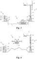
- FIG. 1 and 2 For example, the example of a country road network is shown as a road network 3, and the robot 17 is a land vehicle.
- Fig. 3 shows an alternative embodiment of the system 1, wherein the - here only schematically illustrated - road network 3 is a network of waterways and the robot 17 is formed in the form of an unmanned watercraft.
- the lighting devices 5 are arranged here on the banks of the waterway network 3 and their loading entrance 12 is located at the lower end of the mast 6, so that it is easily accessible from the watercraft robot 17 with a projecting charging coupling 19.
- Fig. 2 also shows the optional use of the masts 6 of the lighting devices 5 for supporting further devices 27 that can be supplied with the battery-buffered wind or solar power from the wind and / or solar module 9 ', 9 ", such as visual or audible signaling devices, Radio transceiver or radio router 27, eg a Wifi hotspot, surveillance cameras, Environmental sensors, traffic signs, traffic information systems, mobile phone charging stations, illuminated advertising space, od.
- further devices 27 can be supplied with the battery-buffered wind or solar power from the wind and / or solar module 9 ', 9 ", such as visual or audible signaling devices, Radio transceiver or radio router 27, eg a Wifi hotspot, surveillance cameras, Environmental sensors, traffic signs, traffic information systems, mobile phone charging stations, illuminated advertising space, od.
- further devices 27 can be supplied with the battery-buffered wind or solar power from the wind and / or solar module 9 ', 9 ", such as visual or audible signaling devices,
- Fig. 4 a further embodiment of the system 1 is shown, in which the road network 3 is a network of airways or aviation roads and the robot 17 is formed as an unmanned aerial vehicle (UAV).
- UAV unmanned aerial vehicle
- This embodiment is particularly suitable for the installation of lighting devices 5 in an impassable and not open to waterways environment 2.
- the lighting devices 5 carry here their charging input 12 at the upper end of the mast 6, so that designed as a UAV robot 17 with its charging coupling 19th can reach the charging input 12 from the air.
- the charging output 14 of the charging station 13 is preferably arranged at the top thereof to allow easy docking of the UAV robot 17.
- the robot 17 in each of the mentioned embodiments may also be provided with mechanical or electronic means for opening doors and gates, e.g. Fenced areas such as dog areas, children's playground od. Like. To be able to approach.
- the robot 17 can also charge itself when docking on a lighting device 5 when the lighting device 5 has an energy surplus in its buffer battery 10.
- the circuit 11 of the lighting device 5 can communicate with the circuit 20 of the robot 17 accordingly, for example via the transmitter 21 and receiver 23 or via a Wired data connection when docking the robot 17 to the lighting device 5, to regulate the charging of the backup battery 10 or the output of any energy surplus to the accumulator 18.
- the circuits 11, 20, 25 of charging station 13, robot 17 and lighting device 5, which are involved in the regulation of the charging of the accumulator 18 and the backup batteries 10, can each be designed for a fast charging function.
Landscapes
- Engineering & Computer Science (AREA)
- Power Engineering (AREA)
- General Engineering & Computer Science (AREA)
- Sustainable Development (AREA)
- Mechanical Engineering (AREA)
- Life Sciences & Earth Sciences (AREA)
- Transportation (AREA)
- Sustainable Energy (AREA)
- Circuit Arrangement For Electric Light Sources In General (AREA)
- Charge And Discharge Circuits For Batteries Or The Like (AREA)
- Control Of Position, Course, Altitude, Or Attitude Of Moving Bodies (AREA)
- Manipulator (AREA)
- Non-Portable Lighting Devices Or Systems Thereof (AREA)
Claims (12)
- Installation d'éclairage d'un environnement, comprenant :une multiplicité de dispositifs d'éclairage (5) qui sont distribués dans l'environnement (2) et sont accessibles par le biais d'un réseau de chemins (3), où chaque dispositif d'éclairage (5) présente une lampe (8), un module éolien et/ou solaire (9', 9") pour la génération de courant éolien, respectivement solaire, alimentant la lampe (8), une batterie tampon (10) pour un stockage intermédiaire du courant éolien, respectivement solaire, et une entrée de charge (12) pour la charge de la batterie tampon (10),caractérisée en ce que l'installation (1) comprend en outre :un poste de charge (13) commun pour les dispositifs d'éclairage (5), lequel est accessible par le réseau de chemins (3) et présente une sortie de charge (14) pour la livraison de courant de charge, etun robot (17) auto-suffisant se déplaçant sur le réseau de chemins (3) qui présente un accumulateur (18) et bascule entre une première position, dans laquelle il s'arrime à la sortie de charge (14) de la station de charge (13) et stocke son courant de charge dans l'accumulateur (18), et plusieurs deuxièmes positions, dans lesquelles il s'arrime respectivement à l'entrée de charge (12) d'un dispositif d'éclairage (5) et charge sa batterie tampon (10) à partir de l'accumulateur (18).
- Installation selon la revendication 1, caractérisée en ce que chaque dispositif d'éclairage (5) présente un circuit de surveillance (11) équipé d'un émetteur (21) pour donner le niveau de charge de la batterie tampon (10) et est conçu pour émettre un signal de demande (22) dans le cas d'un niveau de charge faible par le biais de l'émetteur (21).
- Installation selon la revendication 2, caractérisée en ce que le robot (17) présente un récepteur (23) et est conçu pour s'approcher et recharger, lors de la réception du signal de demande (22), le dispositif d'éclairage (5) émetteur.
- Installation selon la revendication 2, caractérisée en ce que le poste de charge (13) présente un récepteur (24) et est conçu pour envoyer, lors de la réception du signal de demande (22), le robot (17) vers le dispositif d'éclairage (5) émetteur et recharger celui-ci.
- Installation selon l'une des revendications 2 à 4, caractérisée en ce que le signal de demande (22) comporte la position du dispositif d'éclairage (5).
- Installation selon l'une des revendications 2 à 4, caractérisée en ce que le signal de demande (22) comporte un identifiant du dispositif d'éclairage (5) et l'installation (1) comprend une mémoire (26) avec des identifiants et des positions correspondantes des dispositifs d'éclairage (5).
- Installation selon l'une des revendications 1 à 6, caractérisée en ce que le réseau de chemins (3) est un réseau de chemins ruraux et le robot (17) est un véhicule terrestre sans équipage.
- Installation selon l'une des revendications 1 à 6, caractérisée en ce que le réseau de chemins (3) est un réseau de cours d'eau et le robot (17) est une embarcation sans équipage.
- Installation selon la revendication 7 ou la revendication 8, caractérisée en ce que chaque dispositif d'éclairage (5) présente un mât (6), à l'extrémité inférieure duquel se situe l'entrée de charge (12) et à l'extrémité supérieure duquel se situe la lampe (8).
- Installation selon l'une des revendications 1 à 6, caractérisée en ce que le réseau de chemins (3) est un réseau de voies aériennes et le robot (17) est un aéronef sans équipage.
- Installation selon la revendication 10, caractérisée en ce que chaque dispositif d'éclairage (5) présente un mât (6) à l'extrémité supérieure duquel se situe l'entrée de charge (12) .
- Installations selon les revendications 9 ou 11, caractérisées en ce que le mât (6) porte d'autres équipements (27) alimentés en courant, notamment un équipement de signaux optiques ou acoustiques, un émetteur-récepteur radio ou un routeur radio.
Priority Applications (7)
| Application Number | Priority Date | Filing Date | Title |
|---|---|---|---|
| EP16170816.9A EP3249286B1 (fr) | 2016-05-23 | 2016-05-23 | Installation d'eclairage d'un environnement |
| PCT/EP2017/062090 WO2017202714A1 (fr) | 2016-05-23 | 2017-05-19 | Système d'éclairage d'un environnement |
| CN201780031821.3A CN109312901B (zh) | 2016-05-23 | 2017-05-19 | 用于照亮环境的系统 |
| JP2018562196A JP6932728B2 (ja) | 2016-05-23 | 2017-05-19 | 周辺環境を照らすためのシステム |
| RU2018144837A RU2726857C2 (ru) | 2016-05-23 | 2017-05-19 | Установка для освещения окружающей территории |
| BR112018073914-6A BR112018073914B1 (pt) | 2016-05-23 | 2017-05-19 | Instalação para iluminar um ambiente |
| US16/303,711 US10859222B2 (en) | 2016-05-23 | 2017-05-19 | System for illuminating an environment |
Applications Claiming Priority (1)
| Application Number | Priority Date | Filing Date | Title |
|---|---|---|---|
| EP16170816.9A EP3249286B1 (fr) | 2016-05-23 | 2016-05-23 | Installation d'eclairage d'un environnement |
Publications (2)
| Publication Number | Publication Date |
|---|---|
| EP3249286A1 EP3249286A1 (fr) | 2017-11-29 |
| EP3249286B1 true EP3249286B1 (fr) | 2018-11-21 |
Family
ID=56092737
Family Applications (1)
| Application Number | Title | Priority Date | Filing Date |
|---|---|---|---|
| EP16170816.9A Active EP3249286B1 (fr) | 2016-05-23 | 2016-05-23 | Installation d'eclairage d'un environnement |
Country Status (7)
| Country | Link |
|---|---|
| US (1) | US10859222B2 (fr) |
| EP (1) | EP3249286B1 (fr) |
| JP (1) | JP6932728B2 (fr) |
| CN (1) | CN109312901B (fr) |
| BR (1) | BR112018073914B1 (fr) |
| RU (1) | RU2726857C2 (fr) |
| WO (1) | WO2017202714A1 (fr) |
Families Citing this family (6)
| Publication number | Priority date | Publication date | Assignee | Title |
|---|---|---|---|---|
| DE202017103712U1 (de) * | 2017-06-22 | 2018-09-25 | Tridonic Gmbh & Co Kg | Gebäudetechnikvorrichtung und Leuchte mit Energiespeicher, System für deren Versorgung mittels einer mobilen Ladevorrichtung und mobile Ladevorrichtung |
| US11993489B2 (en) * | 2018-07-17 | 2024-05-28 | Mitsubishi Electric Corporation | Elevator system |
| WO2020019600A1 (fr) * | 2018-07-24 | 2020-01-30 | 东旭科技集团有限公司 | Lampadaire présentant une fonction de navigation, système de lampadaire et véhicule aérien sans pilote |
| CN108859822A (zh) * | 2018-08-13 | 2018-11-23 | 郴州金通信息科技有限公司 | 基于风能和太阳能的共享电动车充电桩 |
| RU2743800C1 (ru) * | 2020-07-06 | 2021-02-26 | Сергей Анатольевич Сибиряков | Глобальная логистическая система, включающая модули для перемещения людей, систему транспортировки грузов и используемые в ней транспортные средства |
| JP7602900B2 (ja) * | 2020-12-01 | 2024-12-19 | 河村電器産業株式会社 | 独立電源装置給電システム |
Family Cites Families (27)
| Publication number | Priority date | Publication date | Assignee | Title |
|---|---|---|---|---|
| US4200904A (en) * | 1978-04-14 | 1980-04-29 | Duc Doan | Solar powered street lighting system |
| JPH06133411A (ja) * | 1992-10-13 | 1994-05-13 | Toshiba Corp | 作業ロボットの給電装置 |
| CN2718380Y (zh) | 2004-07-20 | 2005-08-17 | 随魁亭 | 太阳电池和手持发电机供电的半导体照明灯 |
| CN2717093Y (zh) * | 2004-07-29 | 2005-08-10 | 金桂英 | 太阳能交、直流移动供电装置 |
| JP4912577B2 (ja) * | 2004-09-01 | 2012-04-11 | 本田技研工業株式会社 | 2足歩行ロボットの充電システム |
| KR100696134B1 (ko) * | 2005-04-25 | 2007-03-22 | 엘지전자 주식회사 | 이동로봇의 위치 산출 시스템과 그를 이용한 충전대 복귀시스템 및 그 방법 |
| JP2006340482A (ja) * | 2005-06-01 | 2006-12-14 | Ishikawajima Harima Heavy Ind Co Ltd | 発光装置及び発光システム並びに発光装置の電力補完方法 |
| KR100645814B1 (ko) * | 2005-06-07 | 2006-11-23 | 엘지전자 주식회사 | 이동로봇의 자동충전 복귀 시스템 및 그 복귀 방법 |
| CN201100573Y (zh) | 2007-11-16 | 2008-08-13 | 贺立 | 应急灯 |
| US7952319B2 (en) * | 2008-01-07 | 2011-05-31 | Coulomb Technologies, Inc. | Street light mounted network-controlled charge transfer device for electric vehicles |
| DE102009006982A1 (de) * | 2008-02-01 | 2009-08-06 | Continental Teves Ag & Co. Ohg | Ladesystem für Hybrid- und Elektrofahrzeuge |
| CN101527984B (zh) | 2008-03-04 | 2012-07-25 | 宏齐科技股份有限公司 | 高尔夫球场的照明管理系统及其控制方法 |
| RU91406U1 (ru) * | 2009-11-30 | 2010-02-10 | Виталий Владимирович Бегарь | Автономный уличный осветитель |
| RU100851U1 (ru) * | 2010-09-10 | 2010-12-27 | Общество с ограниченной ответственностью "ГРЦ-Вертикаль" | Комбинированная ветросолнечная энергетическая установка со светодиодным излучателем для освещения общественных мест |
| US20120229085A1 (en) * | 2011-03-07 | 2012-09-13 | Lau David M K | System for charging electric vehicle batteries from street lights and parking meters |
| CN201992554U (zh) | 2011-04-19 | 2011-09-28 | 安徽瑞鑫光电有限公司 | 家用太阳能照明装置 |
| US20130134938A1 (en) * | 2011-11-29 | 2013-05-30 | James S. Bianco | Onboard EVSE System for Electric Vehicle |
| US10411495B2 (en) * | 2012-06-13 | 2019-09-10 | Clear Blue Technologies Inc. | System for the monitoring and maintenance of remote autonomously powered lighting installations |
| US9114716B2 (en) | 2013-01-02 | 2015-08-25 | Ford Global Technologies, Llc | Method and apparatus for high-voltage DC charging of battery-electric and plug-in hybrid electric vehicles |
| JP6277585B2 (ja) * | 2013-02-04 | 2018-02-14 | 株式会社Ihi | 非接触給電システム |
| AT514522B1 (de) | 2013-06-19 | 2015-03-15 | Icgh Invest And Consulting Gmbh | LED-Leuchte für den Außenbereich |
| US9113518B2 (en) | 2013-07-11 | 2015-08-18 | Ellenby Technologies, Inc. | Battery powered light source for compartment illumination |
| CN203686846U (zh) | 2013-12-15 | 2014-07-02 | 重庆辉腾光电有限公司 | 双电源智能太阳能交通信号灯 |
| CN104791696B (zh) * | 2015-05-04 | 2017-05-17 | 深圳市斯派克光电科技有限公司 | 路灯组网的控制方法及路灯 |
| RU2593207C1 (ru) * | 2015-06-23 | 2016-08-10 | Общество с ограниченной ответственностью "СТИЛСОФТ" | Способ заряда аккумуляторных батарей беспилотных летательных аппаратов |
| KR20150088983A (ko) | 2015-07-15 | 2015-08-04 | 최창준 | 태양광 기반 도로 시선 유도등 시스템의 관리방법 |
| CN205017052U (zh) | 2015-09-10 | 2016-02-03 | 江苏精一电气科技有限公司 | 基于直流充电设施的城市道路路灯供电网路综合利用系统 |
-
2016
- 2016-05-23 EP EP16170816.9A patent/EP3249286B1/fr active Active
-
2017
- 2017-05-19 JP JP2018562196A patent/JP6932728B2/ja active Active
- 2017-05-19 RU RU2018144837A patent/RU2726857C2/ru active
- 2017-05-19 CN CN201780031821.3A patent/CN109312901B/zh not_active Expired - Fee Related
- 2017-05-19 BR BR112018073914-6A patent/BR112018073914B1/pt not_active IP Right Cessation
- 2017-05-19 WO PCT/EP2017/062090 patent/WO2017202714A1/fr not_active Ceased
- 2017-05-19 US US16/303,711 patent/US10859222B2/en active Active
Non-Patent Citations (1)
| Title |
|---|
| None * |
Also Published As
| Publication number | Publication date |
|---|---|
| JP2019518406A (ja) | 2019-06-27 |
| JP6932728B2 (ja) | 2021-09-08 |
| WO2017202714A1 (fr) | 2017-11-30 |
| EP3249286A1 (fr) | 2017-11-29 |
| CN109312901B (zh) | 2021-01-08 |
| BR112018073914A2 (pt) | 2019-02-26 |
| US10859222B2 (en) | 2020-12-08 |
| RU2726857C2 (ru) | 2020-07-16 |
| CN109312901A (zh) | 2019-02-05 |
| RU2018144837A3 (fr) | 2020-06-25 |
| RU2018144837A (ru) | 2020-06-25 |
| BR112018073914B1 (pt) | 2023-04-04 |
| US20190301692A1 (en) | 2019-10-03 |
Similar Documents
| Publication | Publication Date | Title |
|---|---|---|
| EP3249286B1 (fr) | Installation d'eclairage d'un environnement | |
| EP2071535B1 (fr) | Balisage lumineux portatif pour aéronefs | |
| CN111223316A (zh) | 一种智能交通信号灯系统 | |
| DE102007013129A1 (de) | Beleuchtungsvorrichtung, insbesondere netzunabhängige Beleuchtungsvorrichtung, und Beleuchtungsverbund | |
| DE19928317C2 (de) | Bahnübergangssicherungsanlage | |
| DE3940007C2 (de) | Signalleuchteneinrichtung | |
| EP4197038A1 (fr) | Marquage d'issues de secours dans des véhicules | |
| DE102007038243A1 (de) | Verkehrskonzept für Parallel-Zweiräder | |
| WO1998013945A1 (fr) | Station de base pour systeme radiotelephonique mobile | |
| DE202019005763U1 (de) | Warnvorrichtung | |
| KR20140014422A (ko) | 도로 및 철로에 따라 설치하는 2층 구조물을 이용한 네트워크 기반의 물류 및 교통 및 통신시스템 | |
| DE102014015411A1 (de) | Betonplatte | |
| DE3832688A1 (de) | Markise mit solarzellen | |
| EP1731397A1 (fr) | Système de sécurité pour un passage à niveau protégé | |
| DE10351431A1 (de) | Kommunikationssystem | |
| WO2023057428A1 (fr) | Installation de surveillance de place de stationnement | |
| DE102025111946A1 (de) | System mit mehreren Straßenlaternen und Verfahren zum Betrieb des Systems | |
| US20220383733A1 (en) | Pedestrian traffic light with autonomous energy | |
| DE102005063443A1 (de) | Kommunikationszentrale | |
| DE212016000188U1 (de) | Verbesserungen an oder in Bezug auf Beleuchtungskörper | |
| DE102017207135A1 (de) | Verfahren und Vorrichtung zur Signalisierung der Belegung einer Parkumgebung | |
| CN108831465A (zh) | 一种智能放牧车 | |
| DE102015205092A1 (de) | Drohnenbasisstation für den öffentlichen Raum und eine entsprechend erweiterte Verkehrssignalanlage | |
| DE2636883A1 (de) | System zur fahrzeugortung | |
| DE202022001615U1 (de) | ln Strassenleitpfosten integriertes Verkehrskommunikationssystem |
Legal Events
| Date | Code | Title | Description |
|---|---|---|---|
| PUAI | Public reference made under article 153(3) epc to a published international application that has entered the european phase |
Free format text: ORIGINAL CODE: 0009012 |
|
| STAA | Information on the status of an ep patent application or granted ep patent |
Free format text: STATUS: THE APPLICATION HAS BEEN PUBLISHED |
|
| AK | Designated contracting states |
Kind code of ref document: A1 Designated state(s): AL AT BE BG CH CY CZ DE DK EE ES FI FR GB GR HR HU IE IS IT LI LT LU LV MC MK MT NL NO PL PT RO RS SE SI SK SM TR |
|
| AX | Request for extension of the european patent |
Extension state: BA ME |
|
| STAA | Information on the status of an ep patent application or granted ep patent |
Free format text: STATUS: REQUEST FOR EXAMINATION WAS MADE |
|
| 17P | Request for examination filed |
Effective date: 20180115 |
|
| RBV | Designated contracting states (corrected) |
Designated state(s): AL AT BE BG CH CY CZ DE DK EE ES FI FR GB GR HR HU IE IS IT LI LT LU LV MC MK MT NL NO PL PT RO RS SE SI SK SM TR |
|
| REG | Reference to a national code |
Ref country code: DE Ref legal event code: R079 Ref document number: 502016002548 Country of ref document: DE Free format text: PREVIOUS MAIN CLASS: F21S0009030000 Ipc: F21S0008080000 |
|
| GRAP | Despatch of communication of intention to grant a patent |
Free format text: ORIGINAL CODE: EPIDOSNIGR1 |
|
| RIC1 | Information provided on ipc code assigned before grant |
Ipc: F21S 9/02 20060101ALI20180509BHEP Ipc: F21W 131/103 20060101ALI20180509BHEP Ipc: H02J 7/00 20060101ALI20180509BHEP Ipc: F21S 9/03 20060101ALI20180509BHEP Ipc: F21S 8/08 20060101AFI20180509BHEP |
|
| STAA | Information on the status of an ep patent application or granted ep patent |
Free format text: STATUS: GRANT OF PATENT IS INTENDED |
|
| INTG | Intention to grant announced |
Effective date: 20180614 |
|
| GRAS | Grant fee paid |
Free format text: ORIGINAL CODE: EPIDOSNIGR3 |
|
| GRAA | (expected) grant |
Free format text: ORIGINAL CODE: 0009210 |
|
| STAA | Information on the status of an ep patent application or granted ep patent |
Free format text: STATUS: THE PATENT HAS BEEN GRANTED |
|
| AK | Designated contracting states |
Kind code of ref document: B1 Designated state(s): AL AT BE BG CH CY CZ DE DK EE ES FI FR GB GR HR HU IE IS IT LI LT LU LV MC MK MT NL NO PL PT RO RS SE SI SK SM TR |
|
| REG | Reference to a national code |
Ref country code: CH Ref legal event code: EP |
|
| REG | Reference to a national code |
Ref country code: IE Ref legal event code: FG4D Free format text: LANGUAGE OF EP DOCUMENT: GERMAN |
|
| REG | Reference to a national code |
Ref country code: DE Ref legal event code: R096 Ref document number: 502016002548 Country of ref document: DE |
|
| REG | Reference to a national code |
Ref country code: AT Ref legal event code: REF Ref document number: 1067958 Country of ref document: AT Kind code of ref document: T Effective date: 20181215 |
|
| REG | Reference to a national code |
Ref country code: NL Ref legal event code: MP Effective date: 20181121 |
|
| PG25 | Lapsed in a contracting state [announced via postgrant information from national office to epo] |
Ref country code: FI Free format text: LAPSE BECAUSE OF FAILURE TO SUBMIT A TRANSLATION OF THE DESCRIPTION OR TO PAY THE FEE WITHIN THE PRESCRIBED TIME-LIMIT Effective date: 20181121 Ref country code: NO Free format text: LAPSE BECAUSE OF FAILURE TO SUBMIT A TRANSLATION OF THE DESCRIPTION OR TO PAY THE FEE WITHIN THE PRESCRIBED TIME-LIMIT Effective date: 20190221 Ref country code: IS Free format text: LAPSE BECAUSE OF FAILURE TO SUBMIT A TRANSLATION OF THE DESCRIPTION OR TO PAY THE FEE WITHIN THE PRESCRIBED TIME-LIMIT Effective date: 20190321 Ref country code: ES Free format text: LAPSE BECAUSE OF FAILURE TO SUBMIT A TRANSLATION OF THE DESCRIPTION OR TO PAY THE FEE WITHIN THE PRESCRIBED TIME-LIMIT Effective date: 20181121 Ref country code: LV Free format text: LAPSE BECAUSE OF FAILURE TO SUBMIT A TRANSLATION OF THE DESCRIPTION OR TO PAY THE FEE WITHIN THE PRESCRIBED TIME-LIMIT Effective date: 20181121 Ref country code: HR Free format text: LAPSE BECAUSE OF FAILURE TO SUBMIT A TRANSLATION OF THE DESCRIPTION OR TO PAY THE FEE WITHIN THE PRESCRIBED TIME-LIMIT Effective date: 20181121 Ref country code: LT Free format text: LAPSE BECAUSE OF FAILURE TO SUBMIT A TRANSLATION OF THE DESCRIPTION OR TO PAY THE FEE WITHIN THE PRESCRIBED TIME-LIMIT Effective date: 20181121 Ref country code: BG Free format text: LAPSE BECAUSE OF FAILURE TO SUBMIT A TRANSLATION OF THE DESCRIPTION OR TO PAY THE FEE WITHIN THE PRESCRIBED TIME-LIMIT Effective date: 20190221 |
|
| PG25 | Lapsed in a contracting state [announced via postgrant information from national office to epo] |
Ref country code: PT Free format text: LAPSE BECAUSE OF FAILURE TO SUBMIT A TRANSLATION OF THE DESCRIPTION OR TO PAY THE FEE WITHIN THE PRESCRIBED TIME-LIMIT Effective date: 20190321 Ref country code: RS Free format text: LAPSE BECAUSE OF FAILURE TO SUBMIT A TRANSLATION OF THE DESCRIPTION OR TO PAY THE FEE WITHIN THE PRESCRIBED TIME-LIMIT Effective date: 20181121 Ref country code: NL Free format text: LAPSE BECAUSE OF FAILURE TO SUBMIT A TRANSLATION OF THE DESCRIPTION OR TO PAY THE FEE WITHIN THE PRESCRIBED TIME-LIMIT Effective date: 20181121 Ref country code: GR Free format text: LAPSE BECAUSE OF FAILURE TO SUBMIT A TRANSLATION OF THE DESCRIPTION OR TO PAY THE FEE WITHIN THE PRESCRIBED TIME-LIMIT Effective date: 20190222 Ref country code: SE Free format text: LAPSE BECAUSE OF FAILURE TO SUBMIT A TRANSLATION OF THE DESCRIPTION OR TO PAY THE FEE WITHIN THE PRESCRIBED TIME-LIMIT Effective date: 20181121 Ref country code: AL Free format text: LAPSE BECAUSE OF FAILURE TO SUBMIT A TRANSLATION OF THE DESCRIPTION OR TO PAY THE FEE WITHIN THE PRESCRIBED TIME-LIMIT Effective date: 20181121 |
|
| PG25 | Lapsed in a contracting state [announced via postgrant information from national office to epo] |
Ref country code: PL Free format text: LAPSE BECAUSE OF FAILURE TO SUBMIT A TRANSLATION OF THE DESCRIPTION OR TO PAY THE FEE WITHIN THE PRESCRIBED TIME-LIMIT Effective date: 20181121 Ref country code: CZ Free format text: LAPSE BECAUSE OF FAILURE TO SUBMIT A TRANSLATION OF THE DESCRIPTION OR TO PAY THE FEE WITHIN THE PRESCRIBED TIME-LIMIT Effective date: 20181121 Ref country code: IT Free format text: LAPSE BECAUSE OF FAILURE TO SUBMIT A TRANSLATION OF THE DESCRIPTION OR TO PAY THE FEE WITHIN THE PRESCRIBED TIME-LIMIT Effective date: 20181121 Ref country code: DK Free format text: LAPSE BECAUSE OF FAILURE TO SUBMIT A TRANSLATION OF THE DESCRIPTION OR TO PAY THE FEE WITHIN THE PRESCRIBED TIME-LIMIT Effective date: 20181121 |
|
| REG | Reference to a national code |
Ref country code: DE Ref legal event code: R097 Ref document number: 502016002548 Country of ref document: DE |
|
| PG25 | Lapsed in a contracting state [announced via postgrant information from national office to epo] |
Ref country code: EE Free format text: LAPSE BECAUSE OF FAILURE TO SUBMIT A TRANSLATION OF THE DESCRIPTION OR TO PAY THE FEE WITHIN THE PRESCRIBED TIME-LIMIT Effective date: 20181121 Ref country code: SM Free format text: LAPSE BECAUSE OF FAILURE TO SUBMIT A TRANSLATION OF THE DESCRIPTION OR TO PAY THE FEE WITHIN THE PRESCRIBED TIME-LIMIT Effective date: 20181121 Ref country code: SK Free format text: LAPSE BECAUSE OF FAILURE TO SUBMIT A TRANSLATION OF THE DESCRIPTION OR TO PAY THE FEE WITHIN THE PRESCRIBED TIME-LIMIT Effective date: 20181121 Ref country code: RO Free format text: LAPSE BECAUSE OF FAILURE TO SUBMIT A TRANSLATION OF THE DESCRIPTION OR TO PAY THE FEE WITHIN THE PRESCRIBED TIME-LIMIT Effective date: 20181121 |
|
| PLBE | No opposition filed within time limit |
Free format text: ORIGINAL CODE: 0009261 |
|
| STAA | Information on the status of an ep patent application or granted ep patent |
Free format text: STATUS: NO OPPOSITION FILED WITHIN TIME LIMIT |
|
| 26N | No opposition filed |
Effective date: 20190822 |
|
| PG25 | Lapsed in a contracting state [announced via postgrant information from national office to epo] |
Ref country code: SI Free format text: LAPSE BECAUSE OF FAILURE TO SUBMIT A TRANSLATION OF THE DESCRIPTION OR TO PAY THE FEE WITHIN THE PRESCRIBED TIME-LIMIT Effective date: 20181121 |
|
| REG | Reference to a national code |
Ref country code: CH Ref legal event code: PL |
|
| PG25 | Lapsed in a contracting state [announced via postgrant information from national office to epo] |
Ref country code: CH Free format text: LAPSE BECAUSE OF NON-PAYMENT OF DUE FEES Effective date: 20190531 Ref country code: LI Free format text: LAPSE BECAUSE OF NON-PAYMENT OF DUE FEES Effective date: 20190531 Ref country code: MC Free format text: LAPSE BECAUSE OF FAILURE TO SUBMIT A TRANSLATION OF THE DESCRIPTION OR TO PAY THE FEE WITHIN THE PRESCRIBED TIME-LIMIT Effective date: 20181121 |
|
| REG | Reference to a national code |
Ref country code: BE Ref legal event code: MM Effective date: 20190531 |
|
| PG25 | Lapsed in a contracting state [announced via postgrant information from national office to epo] |
Ref country code: LU Free format text: LAPSE BECAUSE OF NON-PAYMENT OF DUE FEES Effective date: 20190523 |
|
| PG25 | Lapsed in a contracting state [announced via postgrant information from national office to epo] |
Ref country code: TR Free format text: LAPSE BECAUSE OF FAILURE TO SUBMIT A TRANSLATION OF THE DESCRIPTION OR TO PAY THE FEE WITHIN THE PRESCRIBED TIME-LIMIT Effective date: 20181121 |
|
| PG25 | Lapsed in a contracting state [announced via postgrant information from national office to epo] |
Ref country code: IE Free format text: LAPSE BECAUSE OF NON-PAYMENT OF DUE FEES Effective date: 20190523 |
|
| PG25 | Lapsed in a contracting state [announced via postgrant information from national office to epo] |
Ref country code: BE Free format text: LAPSE BECAUSE OF NON-PAYMENT OF DUE FEES Effective date: 20190531 |
|
| PG25 | Lapsed in a contracting state [announced via postgrant information from national office to epo] |
Ref country code: CY Free format text: LAPSE BECAUSE OF FAILURE TO SUBMIT A TRANSLATION OF THE DESCRIPTION OR TO PAY THE FEE WITHIN THE PRESCRIBED TIME-LIMIT Effective date: 20181121 |
|
| PG25 | Lapsed in a contracting state [announced via postgrant information from national office to epo] |
Ref country code: HU Free format text: LAPSE BECAUSE OF FAILURE TO SUBMIT A TRANSLATION OF THE DESCRIPTION OR TO PAY THE FEE WITHIN THE PRESCRIBED TIME-LIMIT; INVALID AB INITIO Effective date: 20160523 Ref country code: MT Free format text: LAPSE BECAUSE OF FAILURE TO SUBMIT A TRANSLATION OF THE DESCRIPTION OR TO PAY THE FEE WITHIN THE PRESCRIBED TIME-LIMIT Effective date: 20181121 |
|
| REG | Reference to a national code |
Ref country code: FR Ref legal event code: PLFP Year of fee payment: 7 |
|
| PG25 | Lapsed in a contracting state [announced via postgrant information from national office to epo] |
Ref country code: MK Free format text: LAPSE BECAUSE OF FAILURE TO SUBMIT A TRANSLATION OF THE DESCRIPTION OR TO PAY THE FEE WITHIN THE PRESCRIBED TIME-LIMIT Effective date: 20181121 |
|
| PGFP | Annual fee paid to national office [announced via postgrant information from national office to epo] |
Ref country code: GB Payment date: 20220523 Year of fee payment: 7 Ref country code: FR Payment date: 20220523 Year of fee payment: 7 |
|
| P01 | Opt-out of the competence of the unified patent court (upc) registered |
Effective date: 20230427 |
|
| GBPC | Gb: european patent ceased through non-payment of renewal fee |
Effective date: 20230523 |
|
| PG25 | Lapsed in a contracting state [announced via postgrant information from national office to epo] |
Ref country code: GB Free format text: LAPSE BECAUSE OF NON-PAYMENT OF DUE FEES Effective date: 20230523 |
|
| PG25 | Lapsed in a contracting state [announced via postgrant information from national office to epo] |
Ref country code: FR Free format text: LAPSE BECAUSE OF NON-PAYMENT OF DUE FEES Effective date: 20230531 |
|
| PGFP | Annual fee paid to national office [announced via postgrant information from national office to epo] |
Ref country code: DE Payment date: 20250522 Year of fee payment: 10 |
|
| PGFP | Annual fee paid to national office [announced via postgrant information from national office to epo] |
Ref country code: AT Payment date: 20250521 Year of fee payment: 10 |