EP3249301A1 - Kanalanordnung mit einspritzanordnungen, die in einem bereich mit wachsender querschnittsfläche einer stromabwärtigen verbrennungsstufe in einem gasturbinenmotor angeordnet sind - Google Patents
Kanalanordnung mit einspritzanordnungen, die in einem bereich mit wachsender querschnittsfläche einer stromabwärtigen verbrennungsstufe in einem gasturbinenmotor angeordnet sind Download PDFInfo
- Publication number
- EP3249301A1 EP3249301A1 EP17170957.9A EP17170957A EP3249301A1 EP 3249301 A1 EP3249301 A1 EP 3249301A1 EP 17170957 A EP17170957 A EP 17170957A EP 3249301 A1 EP3249301 A1 EP 3249301A1
- Authority
- EP
- European Patent Office
- Prior art keywords
- cross
- reactant
- flow
- ducting arrangement
- guiding structure
- Prior art date
- Legal status (The legal status is an assumption and is not a legal conclusion. Google has not performed a legal analysis and makes no representation as to the accuracy of the status listed.)
- Withdrawn
Links
- 238000002485 combustion reaction Methods 0.000 title claims abstract description 59
- 230000000712 assembly Effects 0.000 title abstract description 21
- 238000000429 assembly Methods 0.000 title abstract description 21
- 239000000567 combustion gas Substances 0.000 claims abstract description 32
- 239000000376 reactant Substances 0.000 claims abstract description 32
- 239000007789 gas Substances 0.000 claims abstract description 20
- 238000002347 injection Methods 0.000 claims description 72
- 239000007924 injection Substances 0.000 claims description 72
- 239000000446 fuel Substances 0.000 claims description 12
- 238000011144 upstream manufacturing Methods 0.000 claims description 7
- 230000002093 peripheral effect Effects 0.000 claims description 5
- 238000004519 manufacturing process Methods 0.000 abstract description 27
- 239000000654 additive Substances 0.000 abstract description 10
- 230000000996 additive effect Effects 0.000 abstract description 10
- 238000005516 engineering process Methods 0.000 abstract description 7
- 238000010146 3D printing Methods 0.000 abstract description 4
- 238000002156 mixing Methods 0.000 abstract description 4
- 238000000034 method Methods 0.000 description 14
- 238000013459 approach Methods 0.000 description 6
- 238000010894 electron beam technology Methods 0.000 description 5
- 238000000149 argon plasma sintering Methods 0.000 description 4
- 238000011960 computer-aided design Methods 0.000 description 4
- 238000002844 melting Methods 0.000 description 4
- 230000008018 melting Effects 0.000 description 4
- 230000008901 benefit Effects 0.000 description 3
- 238000007792 addition Methods 0.000 description 2
- 238000001816 cooling Methods 0.000 description 2
- 230000003247 decreasing effect Effects 0.000 description 2
- 238000013461 design Methods 0.000 description 2
- 230000006870 function Effects 0.000 description 2
- 239000002184 metal Substances 0.000 description 2
- 238000005245 sintering Methods 0.000 description 2
- 230000003068 static effect Effects 0.000 description 2
- 230000015572 biosynthetic process Effects 0.000 description 1
- 238000010276 construction Methods 0.000 description 1
- 238000012217 deletion Methods 0.000 description 1
- 230000037430 deletion Effects 0.000 description 1
- 230000001419 dependent effect Effects 0.000 description 1
- 238000010790 dilution Methods 0.000 description 1
- 239000012895 dilution Substances 0.000 description 1
- 239000012530 fluid Substances 0.000 description 1
- 230000004907 flux Effects 0.000 description 1
- 229910000078 germane Inorganic materials 0.000 description 1
- 230000010354 integration Effects 0.000 description 1
- 238000012986 modification Methods 0.000 description 1
- 230000004048 modification Effects 0.000 description 1
- 230000008450 motivation Effects 0.000 description 1
- 230000035515 penetration Effects 0.000 description 1
- 239000000843 powder Substances 0.000 description 1
- 238000007639 printing Methods 0.000 description 1
- 238000012545 processing Methods 0.000 description 1
- 230000002250 progressing effect Effects 0.000 description 1
Images




Classifications
-
- F—MECHANICAL ENGINEERING; LIGHTING; HEATING; WEAPONS; BLASTING
- F23—COMBUSTION APPARATUS; COMBUSTION PROCESSES
- F23R—GENERATING COMBUSTION PRODUCTS OF HIGH PRESSURE OR HIGH VELOCITY, e.g. GAS-TURBINE COMBUSTION CHAMBERS
- F23R3/00—Continuous combustion chambers using liquid or gaseous fuel
- F23R3/28—Continuous combustion chambers using liquid or gaseous fuel characterised by the fuel supply
- F23R3/34—Feeding into different combustion zones
- F23R3/346—Feeding into different combustion zones for staged combustion
-
- F—MECHANICAL ENGINEERING; LIGHTING; HEATING; WEAPONS; BLASTING
- F01—MACHINES OR ENGINES IN GENERAL; ENGINE PLANTS IN GENERAL; STEAM ENGINES
- F01D—NON-POSITIVE DISPLACEMENT MACHINES OR ENGINES, e.g. STEAM TURBINES
- F01D9/00—Stators
- F01D9/02—Nozzles; Nozzle boxes; Stator blades; Guide conduits, e.g. individual nozzles
- F01D9/023—Transition ducts between combustor cans and first stage of the turbine in gas-turbine engines; their cooling or sealings
-
- F—MECHANICAL ENGINEERING; LIGHTING; HEATING; WEAPONS; BLASTING
- F02—COMBUSTION ENGINES; HOT-GAS OR COMBUSTION-PRODUCT ENGINE PLANTS
- F02C—GAS-TURBINE PLANTS; AIR INTAKES FOR JET-PROPULSION PLANTS; CONTROLLING FUEL SUPPLY IN AIR-BREATHING JET-PROPULSION PLANTS
- F02C6/00—Plural gas-turbine plants; Combinations of gas-turbine plants with other apparatus; Adaptations of gas-turbine plants for special use
- F02C6/003—Gas-turbine plants with heaters between turbine stages
-
- F—MECHANICAL ENGINEERING; LIGHTING; HEATING; WEAPONS; BLASTING
- F02—COMBUSTION ENGINES; HOT-GAS OR COMBUSTION-PRODUCT ENGINE PLANTS
- F02C—GAS-TURBINE PLANTS; AIR INTAKES FOR JET-PROPULSION PLANTS; CONTROLLING FUEL SUPPLY IN AIR-BREATHING JET-PROPULSION PLANTS
- F02C7/00—Features, components parts, details or accessories, not provided for in, or of interest apart form groups F02C1/00 - F02C6/00; Air intakes for jet-propulsion plants
- F02C7/22—Fuel supply systems
- F02C7/222—Fuel flow conduits, e.g. manifolds
-
- F—MECHANICAL ENGINEERING; LIGHTING; HEATING; WEAPONS; BLASTING
- F23—COMBUSTION APPARATUS; COMBUSTION PROCESSES
- F23R—GENERATING COMBUSTION PRODUCTS OF HIGH PRESSURE OR HIGH VELOCITY, e.g. GAS-TURBINE COMBUSTION CHAMBERS
- F23R3/00—Continuous combustion chambers using liquid or gaseous fuel
- F23R3/002—Wall structures
-
- F—MECHANICAL ENGINEERING; LIGHTING; HEATING; WEAPONS; BLASTING
- F23—COMBUSTION APPARATUS; COMBUSTION PROCESSES
- F23R—GENERATING COMBUSTION PRODUCTS OF HIGH PRESSURE OR HIGH VELOCITY, e.g. GAS-TURBINE COMBUSTION CHAMBERS
- F23R3/00—Continuous combustion chambers using liquid or gaseous fuel
- F23R3/02—Continuous combustion chambers using liquid or gaseous fuel characterised by the air-flow or gas-flow configuration
-
- F—MECHANICAL ENGINEERING; LIGHTING; HEATING; WEAPONS; BLASTING
- F23—COMBUSTION APPARATUS; COMBUSTION PROCESSES
- F23R—GENERATING COMBUSTION PRODUCTS OF HIGH PRESSURE OR HIGH VELOCITY, e.g. GAS-TURBINE COMBUSTION CHAMBERS
- F23R3/00—Continuous combustion chambers using liquid or gaseous fuel
- F23R3/02—Continuous combustion chambers using liquid or gaseous fuel characterised by the air-flow or gas-flow configuration
- F23R3/04—Air inlet arrangements
-
- F—MECHANICAL ENGINEERING; LIGHTING; HEATING; WEAPONS; BLASTING
- F23—COMBUSTION APPARATUS; COMBUSTION PROCESSES
- F23R—GENERATING COMBUSTION PRODUCTS OF HIGH PRESSURE OR HIGH VELOCITY, e.g. GAS-TURBINE COMBUSTION CHAMBERS
- F23R3/00—Continuous combustion chambers using liquid or gaseous fuel
- F23R3/02—Continuous combustion chambers using liquid or gaseous fuel characterised by the air-flow or gas-flow configuration
- F23R3/04—Air inlet arrangements
- F23R3/045—Air inlet arrangements using pipes
-
- F—MECHANICAL ENGINEERING; LIGHTING; HEATING; WEAPONS; BLASTING
- F23—COMBUSTION APPARATUS; COMBUSTION PROCESSES
- F23R—GENERATING COMBUSTION PRODUCTS OF HIGH PRESSURE OR HIGH VELOCITY, e.g. GAS-TURBINE COMBUSTION CHAMBERS
- F23R3/00—Continuous combustion chambers using liquid or gaseous fuel
- F23R3/02—Continuous combustion chambers using liquid or gaseous fuel characterised by the air-flow or gas-flow configuration
- F23R3/04—Air inlet arrangements
- F23R3/06—Arrangement of apertures along the flame tube
-
- F—MECHANICAL ENGINEERING; LIGHTING; HEATING; WEAPONS; BLASTING
- F23—COMBUSTION APPARATUS; COMBUSTION PROCESSES
- F23R—GENERATING COMBUSTION PRODUCTS OF HIGH PRESSURE OR HIGH VELOCITY, e.g. GAS-TURBINE COMBUSTION CHAMBERS
- F23R3/00—Continuous combustion chambers using liquid or gaseous fuel
- F23R3/02—Continuous combustion chambers using liquid or gaseous fuel characterised by the air-flow or gas-flow configuration
- F23R3/04—Air inlet arrangements
- F23R3/10—Air inlet arrangements for primary air
-
- F—MECHANICAL ENGINEERING; LIGHTING; HEATING; WEAPONS; BLASTING
- F23—COMBUSTION APPARATUS; COMBUSTION PROCESSES
- F23R—GENERATING COMBUSTION PRODUCTS OF HIGH PRESSURE OR HIGH VELOCITY, e.g. GAS-TURBINE COMBUSTION CHAMBERS
- F23R3/00—Continuous combustion chambers using liquid or gaseous fuel
- F23R3/02—Continuous combustion chambers using liquid or gaseous fuel characterised by the air-flow or gas-flow configuration
- F23R3/16—Continuous combustion chambers using liquid or gaseous fuel characterised by the air-flow or gas-flow configuration with devices inside the flame tube or the combustion chamber to influence the air or gas flow
-
- F—MECHANICAL ENGINEERING; LIGHTING; HEATING; WEAPONS; BLASTING
- F23—COMBUSTION APPARATUS; COMBUSTION PROCESSES
- F23R—GENERATING COMBUSTION PRODUCTS OF HIGH PRESSURE OR HIGH VELOCITY, e.g. GAS-TURBINE COMBUSTION CHAMBERS
- F23R3/00—Continuous combustion chambers using liquid or gaseous fuel
- F23R3/02—Continuous combustion chambers using liquid or gaseous fuel characterised by the air-flow or gas-flow configuration
- F23R3/16—Continuous combustion chambers using liquid or gaseous fuel characterised by the air-flow or gas-flow configuration with devices inside the flame tube or the combustion chamber to influence the air or gas flow
- F23R3/18—Flame stabilising means, e.g. flame holders for after-burners of jet-propulsion plants
-
- F—MECHANICAL ENGINEERING; LIGHTING; HEATING; WEAPONS; BLASTING
- F23—COMBUSTION APPARATUS; COMBUSTION PROCESSES
- F23R—GENERATING COMBUSTION PRODUCTS OF HIGH PRESSURE OR HIGH VELOCITY, e.g. GAS-TURBINE COMBUSTION CHAMBERS
- F23R3/00—Continuous combustion chambers using liquid or gaseous fuel
- F23R3/02—Continuous combustion chambers using liquid or gaseous fuel characterised by the air-flow or gas-flow configuration
- F23R3/16—Continuous combustion chambers using liquid or gaseous fuel characterised by the air-flow or gas-flow configuration with devices inside the flame tube or the combustion chamber to influence the air or gas flow
- F23R3/18—Flame stabilising means, e.g. flame holders for after-burners of jet-propulsion plants
- F23R3/20—Flame stabilising means, e.g. flame holders for after-burners of jet-propulsion plants incorporating fuel injection means
-
- F—MECHANICAL ENGINEERING; LIGHTING; HEATING; WEAPONS; BLASTING
- F23—COMBUSTION APPARATUS; COMBUSTION PROCESSES
- F23R—GENERATING COMBUSTION PRODUCTS OF HIGH PRESSURE OR HIGH VELOCITY, e.g. GAS-TURBINE COMBUSTION CHAMBERS
- F23R3/00—Continuous combustion chambers using liquid or gaseous fuel
- F23R3/28—Continuous combustion chambers using liquid or gaseous fuel characterised by the fuel supply
- F23R3/286—Continuous combustion chambers using liquid or gaseous fuel characterised by the fuel supply having fuel-air premixing devices
-
- F—MECHANICAL ENGINEERING; LIGHTING; HEATING; WEAPONS; BLASTING
- F23—COMBUSTION APPARATUS; COMBUSTION PROCESSES
- F23R—GENERATING COMBUSTION PRODUCTS OF HIGH PRESSURE OR HIGH VELOCITY, e.g. GAS-TURBINE COMBUSTION CHAMBERS
- F23R3/00—Continuous combustion chambers using liquid or gaseous fuel
- F23R3/28—Continuous combustion chambers using liquid or gaseous fuel characterised by the fuel supply
- F23R3/34—Feeding into different combustion zones
-
- F—MECHANICAL ENGINEERING; LIGHTING; HEATING; WEAPONS; BLASTING
- F23—COMBUSTION APPARATUS; COMBUSTION PROCESSES
- F23R—GENERATING COMBUSTION PRODUCTS OF HIGH PRESSURE OR HIGH VELOCITY, e.g. GAS-TURBINE COMBUSTION CHAMBERS
- F23R3/00—Continuous combustion chambers using liquid or gaseous fuel
- F23R3/42—Continuous combustion chambers using liquid or gaseous fuel characterised by the arrangement or form of the flame tubes or combustion chambers
-
- F—MECHANICAL ENGINEERING; LIGHTING; HEATING; WEAPONS; BLASTING
- F05—INDEXING SCHEMES RELATING TO ENGINES OR PUMPS IN VARIOUS SUBCLASSES OF CLASSES F01-F04
- F05D—INDEXING SCHEME FOR ASPECTS RELATING TO NON-POSITIVE-DISPLACEMENT MACHINES OR ENGINES, GAS-TURBINES OR JET-PROPULSION PLANTS
- F05D2240/00—Components
- F05D2240/35—Combustors or associated equipment
-
- F—MECHANICAL ENGINEERING; LIGHTING; HEATING; WEAPONS; BLASTING
- F23—COMBUSTION APPARATUS; COMBUSTION PROCESSES
- F23R—GENERATING COMBUSTION PRODUCTS OF HIGH PRESSURE OR HIGH VELOCITY, e.g. GAS-TURBINE COMBUSTION CHAMBERS
- F23R2900/00—Special features of, or arrangements for continuous combustion chambers; Combustion processes therefor
- F23R2900/03341—Sequential combustion chambers or burners
Definitions
- Disclosed embodiments are generally related to combustion turbine engines, such as gas turbine engines and, more particularly, to a ducting arrangement with injector assemblies arranged in a region with an expanding cross-sectional area downstream of the primary combustion stage in a gas turbine engine.
- DCS distributed combustion system
- combustor design approaches such as a distributed combustion system (DCS) approach and an advanced ducting approach
- DCS distributed combustion system
- a number of injector assemblies each may comprise an assembly of an air scoop and a fuel nozzle
- a combustion stage downstream also referred to in the art as a secondary combustion stage or axial combustion stage
- this downstream combustion stage may involve a flow-accelerating structure that passes a cross-flow of combustion gases (e.g., vitiated gases from the main combustion stage) that can reach relatively high subsonic speeds, which is conducive to achieve a decreased static temperature and a reduced combustion residence time.
- combustion gases e.g., vitiated gases from the main combustion stage
- the present inventors have recognized that at the relatively high subsonic speeds of the passing cross-flow of combustion gases, there may be a substantial drop in the total pressure across the downstream combustion stage, which may not be desirable.
- the present inventors propose an innovative ducting arrangement appropriately configured with injector assemblies arranged in a region with expanding cross sectional area in the downstream combustion stage. This is effective to reduce the magnitude of such pressure loss while achieving an effective level of mixing of the injected reactants with the passing cross-flow of combustion gases.
- the ducting arrangement and injector assemblies are appropriately configured to reduce total pressure loss in the downstream combustion stage by reducing perturbations to the speed of the cross-flow.
- the present inventors further propose use of three-dimensional (3D) Printing/Additive Manufacturing (AM) technologies, such as laser sintering, selective laser melting (SLM), direct metal laser sintering (DMLS), electron beam sintering (EBS), electron beam melting (EBM), etc., that may be conducive to cost-effectively making disclosed injector assemblies that may involve complex geometries and miniaturized features and/or conduits.
- 3D three-dimensional
- AM Three-dimensional
- SLM selective laser melting
- DMLS direct metal laser sintering
- EBS electron beam sintering
- EBM electron beam melting
- disclosed ducting arrangements need not be limited to applications involving such a flow-accelerating structure since any application involving a cross-flow comprising a relatively high subsonic Ma number can benefit from disclosed ducting arrangements.
- Ducting arrangement 10 includes a duct 18 in connection with the downstream combustion stage.
- Duct 18 may be fluidly coupled to receive the cross-flow of combustion gases from flow-accelerating structure 12.
- duct 18 comprises a duct segment 23 including an expanding cross-sectional area 24 as the cross-flow of combustion gases travels toward a turbine section (not shown) of the gas turbine engine.
- Combustion gases from the main and the downstream combustion stages travel toward an outlet side 22 of ducting arrangement 10 to be conveyed toward the turbine section of the gas turbine engine via further components not germane relative to disclosed embodiments.
- FIG. 2 is a fragmentary schematic illustrating certain structural details in connection with the downstream combustion duct (i.e., duct 18) and one non-limiting embodiment of injector assembly 26 disposed in duct segment 23 ( FIG. 1 ) of duct 18.
- injector assembly 26 may include a reactant-guiding structure 27 ( FIG. 2 ) arranged to inject a flow of reactants (schematically represented by arrow 28) into the downstream combustion stage to be mixed with the cross-flow of combustion gases.
- ducting arrangement 10 includes a fuel manifold 32 and an air plenum 34 arranged to convey pressurized air from a suitable supply (not shown).
- Fuel manifold 32 and air plenum 34 is each respectively fluidly coupled to supply the reactants (e.g., fuel (schematically represented by arrow 36) and air (schematically represented by arrows 38)) to reactant-guiding structure 27.
- reactant-guiding structure 27 may be configured to achieve a desired injection angle of flow of reactants 28 relative to the cross-flow of combustion gases (schematically represented by angle ⁇ in FIG. 2 ).
- the desired injection angle ⁇ of the flow of reactants relative to the cross-flow of combustion gases may be in a range from approximately 10° to approximately 80°. It will be appreciated that the desired injection angle of the flow of reactants relative to the cross-flow of combustion gases can influence both total pressure loss and jet penetration in the downstream combustion stage. Therefore, an optimum injection angle may be appropriately chosen depending on the needs of a give application, such as cross-flow conditions, etc.
- the injection angle of the flow of reactants may be alternatively characterized relative to the wall of duct segment 23 having the expanding cross-sectional area 24 through which the cross-flow passes.
- the injection may potentially have a range from approximately 10° to approximately 170°, as schematically represented by angle ⁇ in FIG. 2 , so long as the wall geometry (e.g., wall slope, etc.) in a given duct design permits meeting the foregoing range for angle ⁇ .
- duct segment 23 may include a circumferentially-extending passageway 25 arranged to convey further pressurized air.
- passageway 25 is located along a downstream periphery of duct segment 23 to inject a peripheral stream of air (schematically represented by arrows 29) downstream from injector assembly 26.
- This peripheral stream of air is effective to form a film of cooling air along an inner surface of a wall portion of duct 18, which is downstream of expanding cross-sectional area 24.
- a peripheral stream of air may be effective to dilute reactants inside one or more recirculation zones that may form in the downstream combustion stage. This dilution is conducive to reduce local temperatures and NOx formation.
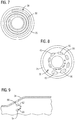
- the circumferentially arranged reactant-guiding structures 27 may form a circular row (schematically represented by line 41) of spaced-apart reactant-guiding structures 27 each including a respective injection orifice 40.
- FIGs. 10-16 are respective views of various non-limiting embodiments of cross-sectional profiles that may be used in connection with injection orifices 40 in the reactant-guiding structures 27 of injector assembly 26.
- FIG. 10 shows an airfoil shaped cross-sectional profile 80. This profile could include a camber 87 depending on the needs of a given application.
- FIG. 11 shows a star-shaped cross-sectional profile 81.
- FIG. 12 shows a cross-shaped cross-sectional profile 82.
- FIG. 13 shows a multi-lobe cross-sectional profile 83.
- FIG. 14 shows a circular cross-sectional profile 84.
- FIG. 10 shows an airfoil shaped cross-sectional profile 80. This profile could include a camber 87 depending on the needs of a given application.
- FIG. 11 shows a star-shaped cross-sectional profile 81.
- FIG. 12 shows a cross-shaped cross-sectional profile 82.
- FIG. 13 shows a multi-lobe cross
- FIG. 15 shows a slotted (e.g., oblong shape) cross-sectional profile 85 having its major axis aligned parallel relative to the direction of the cross-flow 30, whereas FIG. 16 shows a similar cross-sectional profile 86 (e.g., slotted or oblong shape) having its major axis perpendicular relative to the direction of the cross-30.
- FIG. 16 shows a similar cross-sectional profile 86 (e.g., slotted or oblong shape) having its major axis perpendicular relative to the direction of the cross-30.
- injector assembly 26 may comprise a circumferentially-extending reactant-guiding structure 42 configured to provide annular injection in duct segment 23.
- each respective radially-extending slot 44 has an increasing width as the slot extends from a radially inward location to a radially outwardly location, as schematically represented by respective twin-headed arrows 46 and 48.
- This embodiment has the additional benefit of effectively distributing the reactants injected into the downstream combustion stage throughout the entirety of the volumetric expansion of the downstream combustion stage so that the bulk cross flow velocity profile throughout this region can be made substantially constant.
- respective injection orifices at a first row (e.g., row 45) of the plurality of concentric circular rows may comprise an injection area that is larger in size relative to the injection area of respective injection orifices located in rows of the plurality of concentric circular rows located upstream (e.g., rows 43, 41) relative to the first row 45 of respective injection orifices.
- row 45 comprises a row located farthest radially outward relative to the respective radial locations of upstream rows 43, 41.
- injection orifices located within row 43 comprise a larger injection area relative to the injection area of injection orifices located within row 41, since row 43 is in a row located farther radially outward relative to row 41.
- disclosed injector assemblies can be configured to reduce total pressure loss while injecting a flow of reactants into a passing cross-flow of combustion gases and achieving an effective level of mixing of the injected reactants with the passing cross-flow of combustion gases. This may be achieved without affecting the relatively high subsonic speed of the cross-flow of combustion gases passing through the downstream combustion stage of the gas turbine engine.
- disclosed embodiments are expected to be conducive to realizing a combustion system capable of achieving approximately a 65% combined cycle efficiency or greater in a gas turbine engine.
- Disclosed embodiments are also expected to realize a combustion system capable of maintaining stable operation at turbine inlet temperatures of approximately 1700° C and higher while maintaining a relatively low level of NOx emissions, and acceptable temperatures in components of the engine without an increase in cooling air consumption.
- FIG. 17 is a flow chart listing certain steps that may be used in a method for manufacturing disclosed ducting arrangements in a combustion system for a gas turbine engine.
- step 202 allows generating a computer-readable three-dimensional (3D) model, such as a computer aided design (CAD) model, of a ducting arrangement.
- 3D three-dimensional
- CAD computer aided design
- the model defines a digital representation of the ducting arrangement, as described above in the context of the preceding figures.
- step 204 Prior to return step 206, step 204 allows manufacturing the ducting arrangement using an additive manufacturing technique in accordance with the generated three-dimensional model.
- additive manufacturing techniques may include laser sintering, selective laser melting (SLM), direct metal laser sintering (DMLS), electron beam sintering (EBS), electron beam melting (EBM), etc. It will be appreciated that once a model has been generated, or otherwise available (e.g., loaded into a 3D digital printer, or loaded into a processor that controls the additive manufacturing technique), then manufacturing step 204 need not be preceded by a generating step 202.
- step 214 allows successively forming each layer of the ducting arrangement by fusing a metallic powder using a suitable source of energy, such as without limitation, lasing energy or electron beam energy.
- a suitable source of energy such as without limitation, lasing energy or electron beam energy.
Landscapes
- Engineering & Computer Science (AREA)
- Chemical & Material Sciences (AREA)
- Combustion & Propulsion (AREA)
- Mechanical Engineering (AREA)
- General Engineering & Computer Science (AREA)
- Turbine Rotor Nozzle Sealing (AREA)
Applications Claiming Priority (1)
| Application Number | Priority Date | Filing Date | Title |
|---|---|---|---|
| US15/165,195 US10222066B2 (en) | 2016-05-26 | 2016-05-26 | Ducting arrangement with injector assemblies arranged in an expanding cross-sectional area of a downstream combustion stage in a gas turbine engine |
Publications (1)
| Publication Number | Publication Date |
|---|---|
| EP3249301A1 true EP3249301A1 (de) | 2017-11-29 |
Family
ID=58709328
Family Applications (1)
| Application Number | Title | Priority Date | Filing Date |
|---|---|---|---|
| EP17170957.9A Withdrawn EP3249301A1 (de) | 2016-05-26 | 2017-05-15 | Kanalanordnung mit einspritzanordnungen, die in einem bereich mit wachsender querschnittsfläche einer stromabwärtigen verbrennungsstufe in einem gasturbinenmotor angeordnet sind |
Country Status (2)
| Country | Link |
|---|---|
| US (1) | US10222066B2 (de) |
| EP (1) | EP3249301A1 (de) |
Cited By (5)
| Publication number | Priority date | Publication date | Assignee | Title |
|---|---|---|---|---|
| CN111306576A (zh) * | 2018-12-12 | 2020-06-19 | 通用电气公司 | 用于热力发动机的燃烧区段和燃料喷射器组件 |
| EP3865775A1 (de) * | 2020-02-14 | 2021-08-18 | Raytheon Technologies Corporation | Verdünnungsschachtgeometrie eines gasturbinenmotors |
| EP3865774A1 (de) * | 2020-02-14 | 2021-08-18 | Raytheon Technologies Corporation | Integrierte kraftstoffverwirbler |
| US12535214B2 (en) | 2024-04-19 | 2026-01-27 | Rtx Corporation | Attaching powerplant structures together using fuel injector bolts |
| US12584632B2 (en) | 2023-10-27 | 2026-03-24 | Rtx Corporation | Modular injector bolt for an engine |
Families Citing this family (13)
| Publication number | Priority date | Publication date | Assignee | Title |
|---|---|---|---|---|
| US10408455B2 (en) * | 2016-06-14 | 2019-09-10 | General Electric Company | Fuel nozzle assembly with fuel inlet slots |
| US11174792B2 (en) | 2019-05-21 | 2021-11-16 | General Electric Company | System and method for high frequency acoustic dampers with baffles |
| US11156164B2 (en) | 2019-05-21 | 2021-10-26 | General Electric Company | System and method for high frequency accoustic dampers with caps |
| US11959641B2 (en) | 2020-01-31 | 2024-04-16 | Rtx Corporation | Combustor shell with shaped impingement holes |
| CN114517920B (zh) * | 2020-11-19 | 2023-08-08 | 中国航发商用航空发动机有限责任公司 | 喷射装置、燃烧室头部、燃烧室和航空发动机 |
| US11965653B2 (en) * | 2021-06-23 | 2024-04-23 | General Electric Company | Dilution air inlets with notched tip and slotted tail for combustor |
| US12405007B2 (en) | 2021-12-03 | 2025-09-02 | General Electric Company | Combustor size rating for a gas turbine engine using hydrogen fuel |
| US11815269B2 (en) | 2021-12-29 | 2023-11-14 | General Electric Company | Fuel-air mixing assembly in a turbine engine |
| CN121739408A (zh) | 2022-04-06 | 2026-03-27 | 通用电气公司 | 燃烧器偏转器组件 |
| CN116989354A (zh) | 2022-04-26 | 2023-11-03 | 通用电气公司 | 具有成形稀释开口的燃烧器衬里 |
| US12429220B2 (en) | 2023-06-14 | 2025-09-30 | General Electric Company | Combustion section with a primary combustor and a set of secondary combustors |
| US12228286B1 (en) | 2023-09-29 | 2025-02-18 | General Electric Company | Combustion section with a primary combustion chamber and a secondary combustion chamber |
| US12416409B2 (en) | 2024-02-08 | 2025-09-16 | General Electric Company | Gas turbine engine having a combustion section with steam provided to second combustor plenum |
Citations (7)
| Publication number | Priority date | Publication date | Assignee | Title |
|---|---|---|---|---|
| EP0687864A2 (de) * | 1994-05-21 | 1995-12-20 | ROLLS-ROYCE plc | Gasturbinenbrennkammer |
| US5623819A (en) * | 1994-06-07 | 1997-04-29 | Westinghouse Electric Corporation | Method and apparatus for sequentially staged combustion using a catalyst |
| EP0953806A2 (de) * | 1998-05-02 | 1999-11-03 | ROLLS-ROYCE plc | Verbrennungskammer und deren Arbeitsweise |
| US7721547B2 (en) | 2005-06-27 | 2010-05-25 | Siemens Energy, Inc. | Combustion transition duct providing stage 1 tangential turning for turbine engines |
| US8276389B2 (en) | 2008-09-29 | 2012-10-02 | Siemens Energy, Inc. | Assembly for directing combustion gas |
| US8375726B2 (en) | 2008-09-24 | 2013-02-19 | Siemens Energy, Inc. | Combustor assembly in a gas turbine engine |
| US8752386B2 (en) | 2010-05-25 | 2014-06-17 | Siemens Energy, Inc. | Air/fuel supply system for use in a gas turbine engine |
Family Cites Families (11)
| Publication number | Priority date | Publication date | Assignee | Title |
|---|---|---|---|---|
| US4420929A (en) * | 1979-01-12 | 1983-12-20 | General Electric Company | Dual stage-dual mode low emission gas turbine combustion system |
| JPH0772616B2 (ja) * | 1989-05-24 | 1995-08-02 | 株式会社日立製作所 | 燃焼器及びその運転方法 |
| GB9325708D0 (en) * | 1993-12-16 | 1994-02-16 | Rolls Royce Plc | A gas turbine engine combustion chamber |
| US6811744B2 (en) | 1999-07-07 | 2004-11-02 | Optomec Design Company | Forming structures from CAD solid models |
| EP1989486A1 (de) * | 2006-02-28 | 2008-11-12 | Siemens Aktiengesellschaft | Gasturbinenbrenner und verfahren zum betreiben eines gasturbinenbrenners |
| US9188341B2 (en) | 2008-04-11 | 2015-11-17 | General Electric Company | Fuel nozzle |
| US8636496B2 (en) | 2008-05-05 | 2014-01-28 | Georgia Tech Research Corporation | Systems and methods for fabricating three-dimensional objects |
| US8112216B2 (en) | 2009-01-07 | 2012-02-07 | General Electric Company | Late lean injection with adjustable air splits |
| EP2742291B1 (de) * | 2011-08-11 | 2020-07-08 | General Electric Company | System zum einspritzen von brennstoff in einen gasturbinenmotor |
| US9429023B2 (en) | 2013-01-14 | 2016-08-30 | Honeywell International Inc. | Gas turbine engine components and methods for their manufacture using additive manufacturing techniques |
| US9528705B2 (en) | 2014-04-08 | 2016-12-27 | General Electric Company | Trapped vortex fuel injector and method for manufacture |
-
2016
- 2016-05-26 US US15/165,195 patent/US10222066B2/en not_active Expired - Fee Related
-
2017
- 2017-05-15 EP EP17170957.9A patent/EP3249301A1/de not_active Withdrawn
Patent Citations (7)
| Publication number | Priority date | Publication date | Assignee | Title |
|---|---|---|---|---|
| EP0687864A2 (de) * | 1994-05-21 | 1995-12-20 | ROLLS-ROYCE plc | Gasturbinenbrennkammer |
| US5623819A (en) * | 1994-06-07 | 1997-04-29 | Westinghouse Electric Corporation | Method and apparatus for sequentially staged combustion using a catalyst |
| EP0953806A2 (de) * | 1998-05-02 | 1999-11-03 | ROLLS-ROYCE plc | Verbrennungskammer und deren Arbeitsweise |
| US7721547B2 (en) | 2005-06-27 | 2010-05-25 | Siemens Energy, Inc. | Combustion transition duct providing stage 1 tangential turning for turbine engines |
| US8375726B2 (en) | 2008-09-24 | 2013-02-19 | Siemens Energy, Inc. | Combustor assembly in a gas turbine engine |
| US8276389B2 (en) | 2008-09-29 | 2012-10-02 | Siemens Energy, Inc. | Assembly for directing combustion gas |
| US8752386B2 (en) | 2010-05-25 | 2014-06-17 | Siemens Energy, Inc. | Air/fuel supply system for use in a gas turbine engine |
Non-Patent Citations (1)
| Title |
|---|
| GIBSON I.; STUCKER B.; ROSEN D.: "Additive Manufacturing Technologies, 3D Printing, Rapid Prototyping, and Direct Digital Manufacturing", 2010, SPRINGER |
Cited By (9)
| Publication number | Priority date | Publication date | Assignee | Title |
|---|---|---|---|---|
| CN111306576A (zh) * | 2018-12-12 | 2020-06-19 | 通用电气公司 | 用于热力发动机的燃烧区段和燃料喷射器组件 |
| CN111306576B (zh) * | 2018-12-12 | 2022-03-29 | 通用电气公司 | 用于热力发动机的燃烧区段和燃料喷射器组件 |
| US11286884B2 (en) | 2018-12-12 | 2022-03-29 | General Electric Company | Combustion section and fuel injector assembly for a heat engine |
| EP3865775A1 (de) * | 2020-02-14 | 2021-08-18 | Raytheon Technologies Corporation | Verdünnungsschachtgeometrie eines gasturbinenmotors |
| EP3865774A1 (de) * | 2020-02-14 | 2021-08-18 | Raytheon Technologies Corporation | Integrierte kraftstoffverwirbler |
| US11543127B2 (en) | 2020-02-14 | 2023-01-03 | Raytheon Technologies Corporation | Gas turbine engine dilution chute geometry |
| US11846421B2 (en) | 2020-02-14 | 2023-12-19 | Rtx Corporation | Integrated fuel swirlers |
| US12584632B2 (en) | 2023-10-27 | 2026-03-24 | Rtx Corporation | Modular injector bolt for an engine |
| US12535214B2 (en) | 2024-04-19 | 2026-01-27 | Rtx Corporation | Attaching powerplant structures together using fuel injector bolts |
Also Published As
| Publication number | Publication date |
|---|---|
| US20170343217A1 (en) | 2017-11-30 |
| US10222066B2 (en) | 2019-03-05 |
Similar Documents
| Publication | Publication Date | Title |
|---|---|---|
| US10222066B2 (en) | Ducting arrangement with injector assemblies arranged in an expanding cross-sectional area of a downstream combustion stage in a gas turbine engine | |
| US11029030B2 (en) | Ducting arrangement with injector assemblies configured to form a shielding flow of air injected into a combustion stage in a gas turbine engine | |
| EP3475617B1 (de) | Verbrennungssystem mit injektoranordnung | |
| CA2720197C (en) | Swirlers and method of manufacturing | |
| EP3436746B1 (de) | Einspritzanordnung und leitungsanordnung mit solchen einspritzanordnungen in einem verbrennungssystem für einen gasturbinenmotor | |
| US10095218B2 (en) | Method and computer-readable model for additively manufacturing ducting arrangement with injector assemblies forming a shielding flow of air | |
| US10215038B2 (en) | Method and computer-readable model for additively manufacturing ducting arrangement for a gas turbine engine | |
| EP2971970B1 (de) | Dublettenbrenner mit gegenwirbel | |
| US20170260866A1 (en) | Ducting arrangement in a combustion system of a gas turbine engine | |
| US20170284676A1 (en) | Method and computer-readable model for additively manufacturing injector assembly or ducting arrangement including such injector assemblies | |
| WO2009126403A2 (en) | Swirlers and method of manufacturing | |
| US20170261964A1 (en) | Method and computer-readable model for additively manufacturing ducting arrangement for a combustion system in a gas turbine engine | |
| US12326260B1 (en) | Axial fuel stage injector creating air curtain | |
| US12618564B2 (en) | Axial fuel stage injector with axially elongated mixing chambers, and combustor and gt system including same | |
| US12474055B2 (en) | Axial fuel stage injector with axially elongated mixing chambers with axially wavy inlets | |
| US12601490B2 (en) | Axial fuel stage injector with multiple mixing chambers, and combustor and GT system including same | |
| US20250347415A1 (en) | Axial fuel stage injector with axially elongated mixing chambers, and combustor and gt system including same |
Legal Events
| Date | Code | Title | Description |
|---|---|---|---|
| PUAI | Public reference made under article 153(3) epc to a published international application that has entered the european phase |
Free format text: ORIGINAL CODE: 0009012 |
|
| STAA | Information on the status of an ep patent application or granted ep patent |
Free format text: STATUS: THE APPLICATION HAS BEEN PUBLISHED |
|
| AK | Designated contracting states |
Kind code of ref document: A1 Designated state(s): AL AT BE BG CH CY CZ DE DK EE ES FI FR GB GR HR HU IE IS IT LI LT LU LV MC MK MT NL NO PL PT RO RS SE SI SK SM TR |
|
| AX | Request for extension of the european patent |
Extension state: BA ME |
|
| STAA | Information on the status of an ep patent application or granted ep patent |
Free format text: STATUS: REQUEST FOR EXAMINATION WAS MADE |
|
| 17P | Request for examination filed |
Effective date: 20180525 |
|
| RBV | Designated contracting states (corrected) |
Designated state(s): AL AT BE BG CH CY CZ DE DK EE ES FI FR GB GR HR HU IE IS IT LI LT LU LV MC MK MT NL NO PL PT RO RS SE SI SK SM TR |
|
| GRAP | Despatch of communication of intention to grant a patent |
Free format text: ORIGINAL CODE: EPIDOSNIGR1 |
|
| STAA | Information on the status of an ep patent application or granted ep patent |
Free format text: STATUS: GRANT OF PATENT IS INTENDED |
|
| INTG | Intention to grant announced |
Effective date: 20181128 |
|
| STAA | Information on the status of an ep patent application or granted ep patent |
Free format text: STATUS: THE APPLICATION IS DEEMED TO BE WITHDRAWN |
|
| 18D | Application deemed to be withdrawn |
Effective date: 20190409 |