EP3249314A1 - Système d'apport de chaleur - Google Patents
Système d'apport de chaleur Download PDFInfo
- Publication number
- EP3249314A1 EP3249314A1 EP15878909.9A EP15878909A EP3249314A1 EP 3249314 A1 EP3249314 A1 EP 3249314A1 EP 15878909 A EP15878909 A EP 15878909A EP 3249314 A1 EP3249314 A1 EP 3249314A1
- Authority
- EP
- European Patent Office
- Prior art keywords
- heat
- temperature
- hot water
- heat medium
- power supply
- Prior art date
- Legal status (The legal status is an assumption and is not a legal conclusion. Google has not performed a legal analysis and makes no representation as to the accuracy of the status listed.)
- Granted
Links
Images


Classifications
-
- F—MECHANICAL ENGINEERING; LIGHTING; HEATING; WEAPONS; BLASTING
- F24—HEATING; RANGES; VENTILATING
- F24D—DOMESTIC- OR SPACE-HEATING SYSTEMS, e.g. CENTRAL HEATING SYSTEMS; DOMESTIC HOT-WATER SUPPLY SYSTEMS; ELEMENTS OR COMPONENTS THEREFOR
- F24D17/00—Domestic hot-water supply systems
- F24D17/0036—Domestic hot-water supply systems with combination of different kinds of heating means
-
- F—MECHANICAL ENGINEERING; LIGHTING; HEATING; WEAPONS; BLASTING
- F02—COMBUSTION ENGINES; HOT-GAS OR COMBUSTION-PRODUCT ENGINE PLANTS
- F02G—HOT GAS OR COMBUSTION-PRODUCT POSITIVE-DISPLACEMENT ENGINE PLANTS; USE OF WASTE HEAT OF COMBUSTION ENGINES; NOT OTHERWISE PROVIDED FOR
- F02G5/00—Profiting from waste heat of combustion engines, not otherwise provided for
- F02G5/02—Profiting from waste heat of exhaust gases
- F02G5/04—Profiting from waste heat of exhaust gases in combination with other waste heat from combustion engines
-
- F—MECHANICAL ENGINEERING; LIGHTING; HEATING; WEAPONS; BLASTING
- F24—HEATING; RANGES; VENTILATING
- F24D—DOMESTIC- OR SPACE-HEATING SYSTEMS, e.g. CENTRAL HEATING SYSTEMS; DOMESTIC HOT-WATER SUPPLY SYSTEMS; ELEMENTS OR COMPONENTS THEREFOR
- F24D12/00—Other central heating systems
- F24D12/02—Other central heating systems having more than one heat source
-
- F—MECHANICAL ENGINEERING; LIGHTING; HEATING; WEAPONS; BLASTING
- F24—HEATING; RANGES; VENTILATING
- F24D—DOMESTIC- OR SPACE-HEATING SYSTEMS, e.g. CENTRAL HEATING SYSTEMS; DOMESTIC HOT-WATER SUPPLY SYSTEMS; ELEMENTS OR COMPONENTS THEREFOR
- F24D17/00—Domestic hot-water supply systems
- F24D17/0005—Domestic hot-water supply systems using recuperation of waste heat
- F24D17/001—Domestic hot-water supply systems using recuperation of waste heat with accumulation of heated water
-
- F—MECHANICAL ENGINEERING; LIGHTING; HEATING; WEAPONS; BLASTING
- F24—HEATING; RANGES; VENTILATING
- F24D—DOMESTIC- OR SPACE-HEATING SYSTEMS, e.g. CENTRAL HEATING SYSTEMS; DOMESTIC HOT-WATER SUPPLY SYSTEMS; ELEMENTS OR COMPONENTS THEREFOR
- F24D17/00—Domestic hot-water supply systems
- F24D17/0036—Domestic hot-water supply systems with combination of different kinds of heating means
- F24D17/0052—Domestic hot-water supply systems with combination of different kinds of heating means recuperated waste heat and conventional heating means
- F24D17/0057—Domestic hot-water supply systems with combination of different kinds of heating means recuperated waste heat and conventional heating means with accumulation of the heated water
-
- F—MECHANICAL ENGINEERING; LIGHTING; HEATING; WEAPONS; BLASTING
- F24—HEATING; RANGES; VENTILATING
- F24D—DOMESTIC- OR SPACE-HEATING SYSTEMS, e.g. CENTRAL HEATING SYSTEMS; DOMESTIC HOT-WATER SUPPLY SYSTEMS; ELEMENTS OR COMPONENTS THEREFOR
- F24D19/00—Details
- F24D19/10—Arrangement or mounting of control or safety devices
- F24D19/1006—Arrangement or mounting of control or safety devices for water heating systems
- F24D19/1066—Arrangement or mounting of control or safety devices for water heating systems for the combination of central heating and domestic hot water
-
- F—MECHANICAL ENGINEERING; LIGHTING; HEATING; WEAPONS; BLASTING
- F24—HEATING; RANGES; VENTILATING
- F24D—DOMESTIC- OR SPACE-HEATING SYSTEMS, e.g. CENTRAL HEATING SYSTEMS; DOMESTIC HOT-WATER SUPPLY SYSTEMS; ELEMENTS OR COMPONENTS THEREFOR
- F24D3/00—Hot-water central heating systems
- F24D3/08—Hot-water central heating systems in combination with systems for domestic hot-water supply
- F24D3/082—Hot water storage tanks specially adapted therefor
-
- F—MECHANICAL ENGINEERING; LIGHTING; HEATING; WEAPONS; BLASTING
- F24—HEATING; RANGES; VENTILATING
- F24H—FLUID HEATERS, e.g. WATER OR AIR HEATERS, HAVING HEAT-GENERATING MEANS, e.g. HEAT PUMPS, IN GENERAL
- F24H1/00—Water heaters, e.g. boilers, continuous-flow heaters or water-storage heaters
-
- F—MECHANICAL ENGINEERING; LIGHTING; HEATING; WEAPONS; BLASTING
- F24—HEATING; RANGES; VENTILATING
- F24D—DOMESTIC- OR SPACE-HEATING SYSTEMS, e.g. CENTRAL HEATING SYSTEMS; DOMESTIC HOT-WATER SUPPLY SYSTEMS; ELEMENTS OR COMPONENTS THEREFOR
- F24D2200/00—Heat sources or energy sources
- F24D2200/04—Gas or oil fired boiler
-
- F—MECHANICAL ENGINEERING; LIGHTING; HEATING; WEAPONS; BLASTING
- F24—HEATING; RANGES; VENTILATING
- F24D—DOMESTIC- OR SPACE-HEATING SYSTEMS, e.g. CENTRAL HEATING SYSTEMS; DOMESTIC HOT-WATER SUPPLY SYSTEMS; ELEMENTS OR COMPONENTS THEREFOR
- F24D2200/00—Heat sources or energy sources
- F24D2200/16—Waste heat
- F24D2200/26—Internal combustion engine
-
- F—MECHANICAL ENGINEERING; LIGHTING; HEATING; WEAPONS; BLASTING
- F24—HEATING; RANGES; VENTILATING
- F24D—DOMESTIC- OR SPACE-HEATING SYSTEMS, e.g. CENTRAL HEATING SYSTEMS; DOMESTIC HOT-WATER SUPPLY SYSTEMS; ELEMENTS OR COMPONENTS THEREFOR
- F24D2220/00—Components of central heating installations excluding heat sources
- F24D2220/04—Sensors
- F24D2220/042—Temperature sensors
-
- Y—GENERAL TAGGING OF NEW TECHNOLOGICAL DEVELOPMENTS; GENERAL TAGGING OF CROSS-SECTIONAL TECHNOLOGIES SPANNING OVER SEVERAL SECTIONS OF THE IPC; TECHNICAL SUBJECTS COVERED BY FORMER USPC CROSS-REFERENCE ART COLLECTIONS [XRACs] AND DIGESTS
- Y02—TECHNOLOGIES OR APPLICATIONS FOR MITIGATION OR ADAPTATION AGAINST CLIMATE CHANGE
- Y02B—CLIMATE CHANGE MITIGATION TECHNOLOGIES RELATED TO BUILDINGS, e.g. HOUSING, HOUSE APPLIANCES OR RELATED END-USER APPLICATIONS
- Y02B10/00—Integration of renewable energy sources in buildings
- Y02B10/20—Solar thermal
-
- Y—GENERAL TAGGING OF NEW TECHNOLOGICAL DEVELOPMENTS; GENERAL TAGGING OF CROSS-SECTIONAL TECHNOLOGIES SPANNING OVER SEVERAL SECTIONS OF THE IPC; TECHNICAL SUBJECTS COVERED BY FORMER USPC CROSS-REFERENCE ART COLLECTIONS [XRACs] AND DIGESTS
- Y02—TECHNOLOGIES OR APPLICATIONS FOR MITIGATION OR ADAPTATION AGAINST CLIMATE CHANGE
- Y02B—CLIMATE CHANGE MITIGATION TECHNOLOGIES RELATED TO BUILDINGS, e.g. HOUSING, HOUSE APPLIANCES OR RELATED END-USER APPLICATIONS
- Y02B10/00—Integration of renewable energy sources in buildings
- Y02B10/70—Hybrid systems, e.g. uninterruptible or back-up power supplies integrating renewable energies
-
- Y—GENERAL TAGGING OF NEW TECHNOLOGICAL DEVELOPMENTS; GENERAL TAGGING OF CROSS-SECTIONAL TECHNOLOGIES SPANNING OVER SEVERAL SECTIONS OF THE IPC; TECHNICAL SUBJECTS COVERED BY FORMER USPC CROSS-REFERENCE ART COLLECTIONS [XRACs] AND DIGESTS
- Y02—TECHNOLOGIES OR APPLICATIONS FOR MITIGATION OR ADAPTATION AGAINST CLIMATE CHANGE
- Y02B—CLIMATE CHANGE MITIGATION TECHNOLOGIES RELATED TO BUILDINGS, e.g. HOUSING, HOUSE APPLIANCES OR RELATED END-USER APPLICATIONS
- Y02B30/00—Energy efficient heating, ventilation or air conditioning [HVAC]
- Y02B30/18—Domestic hot-water supply systems using recuperated or waste heat
-
- Y—GENERAL TAGGING OF NEW TECHNOLOGICAL DEVELOPMENTS; GENERAL TAGGING OF CROSS-SECTIONAL TECHNOLOGIES SPANNING OVER SEVERAL SECTIONS OF THE IPC; TECHNICAL SUBJECTS COVERED BY FORMER USPC CROSS-REFERENCE ART COLLECTIONS [XRACs] AND DIGESTS
- Y02—TECHNOLOGIES OR APPLICATIONS FOR MITIGATION OR ADAPTATION AGAINST CLIMATE CHANGE
- Y02E—REDUCTION OF GREENHOUSE GAS [GHG] EMISSIONS, RELATED TO ENERGY GENERATION, TRANSMISSION OR DISTRIBUTION
- Y02E20/00—Combustion technologies with mitigation potential
- Y02E20/14—Combined heat and power generation [CHP]
-
- Y—GENERAL TAGGING OF NEW TECHNOLOGICAL DEVELOPMENTS; GENERAL TAGGING OF CROSS-SECTIONAL TECHNOLOGIES SPANNING OVER SEVERAL SECTIONS OF THE IPC; TECHNICAL SUBJECTS COVERED BY FORMER USPC CROSS-REFERENCE ART COLLECTIONS [XRACs] AND DIGESTS
- Y02—TECHNOLOGIES OR APPLICATIONS FOR MITIGATION OR ADAPTATION AGAINST CLIMATE CHANGE
- Y02P—CLIMATE CHANGE MITIGATION TECHNOLOGIES IN THE PRODUCTION OR PROCESSING OF GOODS
- Y02P80/00—Climate change mitigation technologies for sector-wide applications
- Y02P80/10—Efficient use of energy, e.g. using compressed air or pressurized fluid as energy carrier
- Y02P80/15—On-site combined power, heat or cool generation or distribution, e.g. combined heat and power [CHP] supply
Definitions
- the present invention relates to a heat supply system that is provided with a plurality of heat source devices that heat a heat medium, the heat supply system supplying the heat medium to a plurality of heat utilization devices that utilize heat being held by the heat medium.
- heat supply systems that allow a plurality of heat utilization devices, such as a hot water supply device or an indoor heating device, to utilize heat generated by a plurality of heat source devices.
- a plurality of heat utilization devices such as a hot water supply device or an indoor heating device
- warm water in which heat generated by a plurality of heat source devices, namely a heat pump (2) and an external heat source (3), has been recovered is supplied to a plurality of heat utilization devices, namely a hot water storage tank (4) and an indoor heating device (5), while flowing through a water circuit (25) and warm water circuits (30A and 30B).
- a priority rank when operating the heat pump (2) and the external heat source (3) is set in advance. Also, the heat pump (2) and the external heat source (3) are operated in the order of that priority rank according to a load state.
- Patent Document 1 JP 2013-104596A
- the plurality of heat source devices are not necessarily used differently based on specific states of the plurality of heat utilization devices. For example, in a case of increasing the temperature of hot water in the hot water storage tank, if there is only a small amount of high temperature hot water remaining in the hot water storage tank, the hot water in the hot water storage tank must be immediately heated, so it is preferable to operate a heat source device having a large heat output, even though energy efficiency is low. On the other hand, if there is a relatively large amount of high temperature hot water remaining in the hot water storage tank, it is acceptable to slowly increase the temperature of the hot water in the hot water storage tank over time, so it is preferable to operate a heat source device having high energy efficiency, even though the heat output is small.
- the present invention has been made in view of the above problems, and it is an object thereof to provide a heat supply system in which it is possible to efficiently operate a plurality of heat source devices according to the state of a heat utilization device.
- the heat supply system in a characteristic configuration of a heat supply system according to the present invention for attaining the above object, in a heat supply system having a plurality of heat source devices that heat a heat medium, the heat supply system supplying the heat medium to a plurality of heat utilization devices that use heat being held by the heat medium, the heat supply system includes:
- the first temperature detected by the first temperature detection unit is the temperature of the hot water stored relatively lower inside of the tank than water of the second temperature detected by the second temperature detection unit.
- the first lower limit temperature is a temperature that is the second lower limit temperature or more.
- the heat medium return path and the heat medium outward path connecting the combined heat and power supply device, the boiler device, and the hot water storage device are configured such that the heat medium at a relatively low temperature after heat has been used by the hot water storage device is supplied in parallel to each of the combined heat and power supply device and the boiler device, and the heat medium at a relatively high temperature after heating by each of the combined heat and power supply device and the boiler device is supplied to the hot water storage device. That is, the heat medium heated by operation of the combined heat and power supply device is used for a temperature increase operation in the hot water storage device without passing through the boiler device, which is not operating. As a result, it is possible to perform a temperature increase operation in the hot water storage device while effectively utilizing heat generated by the combined heat and power supply device.
- the boiler device with a large heat output is operated in addition to the combined heat and power supply device to increase the temperature of the hot water.
- the heat supply system in a heat supply system having a plurality of heat source devices that heat a heat medium, the heat supply system supplying the heat medium to a plurality of heat utilization devices that use heat being held by the heat medium, the heat supply system includes:
- the first lower limit temperature which is a reference temperature at the time of starting operation of the combined heat and power supply device, is a temperature higher than the second lower limit temperature, which is a reference temperature at the time of starting operation of the boiler device.
- the temperature of the hot water detected by the temperature detection unit reaches the first lower limit temperature or less earlier in time than the temperature of the hot water detected by the temperature detection unit reaches the second lower limit temperature or less.
- a temperature increase operation of the hot water is started earlier for the combined heat and power supply device, which has high energy efficiency, than for the boiler device.
- the heat medium return path and the heat medium outward path connecting the combined heat and power supply device, the boiler device, and the hot water storage device are configured such that the heat medium at a relatively low temperature after heat has been used by the hot water storage device is supplied in parallel to each of the combined heat and power supply device and the boiler device, and the heat medium at a relatively high temperature after heating by each of the combined heat and power supply device and the boiler device is supplied to the hot water storage device. That is, the heat medium heated by operation of the combined heat and power supply device is used for a temperature increase operation in the hot water storage device without passing through the boiler device, which is not operating. As a result, it is possible to perform a temperature increase operation in the hot water storage device while effectively utilizing heat generated by the combined heat and power supply device.
- the boiler device with a large heat output is operated in addition to the combined heat and power supply device to increase the temperature of the hot water.
- a temperature increase permitted time zone where a temperature increase operation of the hot water stored inside of the tank of the hot water storage device is permitted, and a temperature increase unpermitted time zone where a temperature increase operation is not permitted are set, in one day, a boiler permitted time zone where operation of the boiler device is permitted, and a boiler unpermitted time zone where operation of the boiler device is not permitted, are set, in one day, a combined heat and power supply permitted time zone where operation of the combined heat and power supply device is permitted, and a combined heat and power supply unpermitted time zone where operation of the combined heat and power supply device is not permitted, are set, when the current time is in the temperature increase permitted time zone and the combined heat and power supply permitted time zone, and the first temperature is the first lower limit temperature or less, the control device operates the combined heat and power supply device, and operates the flow state adjustment device such that the heat medium circulates between the combined heat and power supply device and the hot water storage device through the heat medium return path and
- a partial time zone including the start time of one of the individual temperature increase time zones is set so as to overlap in time with the combined heat and power supply permitted time zone, and so as to not overlap in time with the boiler permitted time zone, and a time zone after the partial time zone is set so as to overlap in time with the combined heat and power supply permitted time zone and the boiler permitted time zone.
- a partial time zone including the start time of one of the individual temperature increase time zones only heat generated by the combined heat and power supply device can be utilized in a temperature increase operation of the hot water storage device.
- both the heat generated by the combined heat and power supply device and the heat generated by the boiler device can be utilized in a temperature increase operation of the hot water storage device.
- in the temperature increase permitted time zone in one day there is at least one individual temperature increase time zone that is continuous in time, and one of the individual temperature increase time zones is set so as to overlap in time with the combined heat and power supply permitted time zone, and so as to not overlap in time with the boiler permitted time zone.
- a room temperature detection unit that detects the temperature of air within a room to be heated by the indoor heating device is provided, in one day, an indoor heating permitted time zone where operation of the indoor heating device is permitted, and an indoor heating unpermitted time zone where operation of the indoor heating device is not permitted, are set, when the current time is in the indoor heating permitted time zone and the combined heat and power supply permitted time zone, and the temperature of the air detected by the room temperature detection unit is a third lower limit temperature or less, where an indoor heating operation using the combined heat and power supply device is permitted, the control device operates the combined heat and power supply device, and operates the flow state adjustment device such that the heat medium circulates between the combined heat and power supply device and the indoor heating device through the heat medium return path and the heat medium outward path, thereby executing an indoor heating operation using the combined heat and power supply device, when the current time is in the indoor heating permitted time zone and the boiler permitted time zone, and the temperature of the air detected by the room temperature detection unit is a fourth
- the third lower limit temperature is set to a temperature higher than the fourth lower limit temperature, so the temperature of the air detected by the room temperature detection unit reaches the third lower limit temperature before the temperature of the air detected by the room temperature detection unit reaches the fourth lower limit temperature. That is, even when the current time is in the indoor heating permitted time zone, the combined heat and power supply permitted time zone, and the boiler permitted time zone, that is, even when the combined heat and power supply device can be operated based on the value of the air temperature and the boiler device can be operated based on the value of the air temperature, the air temperature reaches the third lower limit temperature or less before the air temperature reaches the fourth lower limit temperature or less, so the combined heat and power supply device, which has high energy efficiency, is utilized first for indoor heating operation.
- the control device while the control device is executing an indoor heating operation using the combined heat and power supply device, if the temperature of the air detected by the room temperature detection unit is a third upper limit temperature or more, where an indoor heating operation using the combined heat and power supply device is not permitted, the control device stops the combined heat and power supply device, while the control device is executing an indoor heating operation using the boiler device, if the temperature of the air detected by the room temperature detection unit is a fourth upper limit temperature or more, where an indoor heating operation using the boiler device is not permitted, the control device stops the boiler device, the third upper limit temperature is set to a temperature higher than the third lower limit temperature, the fourth upper limit temperature is set to a temperature higher than the fourth lower limit temperature, and the third upper limit temperature is set to a temperature higher than the fourth upper limit temperature.
- the third upper limit temperature is set to a temperature higher than the fourth upper limit temperature, so the temperature of the air detected by the room temperature detection unit reaches the fourth upper limit temperature before the temperature of the air detected by the room temperature detection unit reaches the third upper limit temperature. That is, even if an indoor heating operation was executed utilizing both the combined heat and power supply device and the boiler device, the boiler device stops first. As a result, the combined heat and power supply device, which has high energy efficiency, is utilized for the indoor heating operation for a longer period.
- the control device while the control device is executing a temperature increase operation by the combined heat and power supply device, if the first temperature is a first upper limit temperature or more, where a temperature increase operation by the combined heat and power supply device is not permitted, the control device stops the combined heat and power supply device, while the control device is executing a temperature increase operation by the boiler device, if the second temperature is a second upper limit temperature or more, where a temperature increase operation by the boiler device is not permitted, the control device stops the boiler device, the first upper limit temperature is set to a temperature higher than the first lower limit temperature, the second upper limit temperature is set to a temperature higher than the second lower limit temperature, and the first upper limit temperature is set to a temperature higher than the second upper limit temperature.
- the first upper limit temperature is set to a temperature higher than the second upper limit temperature, so the second temperature can be expected to reach the second upper limit temperature before the first temperature reaches the first upper limit temperature. That is, even if a temperature increase operation was executed utilizing both the combined heat and power supply device and the boiler device, the boiler device can be expected to stop first. As a result, the combined heat and power supply device, which has high energy efficiency, is utilized for a temperature increase operation of the hot water for a longer period.
- a temperature difference between the first upper limit temperature and the first lower limit temperature is set smaller than a temperature difference between the second upper limit temperature and the second lower limit temperature.
- operation of the combined heat and power supply device can be started at an early stage if the temperature of the hot water inside of the tank of the hot water storage device decreases slightly, this operation continues until the temperature of the hot water reaches a relatively high temperature, operation of the boiler device does not start until the temperature of the hot water inside of the tank decreases greatly, and this operation is stopped as soon as possible.
- FIG. 1 shows the configuration of the heat supply system.
- the heat supply system includes a plurality of heat source devices (a combined heat and power supply device CG and a boiler device 1), a second heat medium supply path 3 as a heat medium outward path, a second heat medium return path 2 as a heat medium return path, flow state adjustment devices (a circulation pump 44, a second pump 33, an opening/closing valve 6, and an opening/closing valve 7), and a control device C.
- a heat source devices a combined heat and power supply device CG and a boiler device 1
- a second heat medium supply path 3 as a heat medium outward path
- a second heat medium return path 2 as a heat medium return path
- flow state adjustment devices a circulation pump 44, a second pump 33, an opening/closing valve 6, and an opening/closing valve 7
- the combined heat and power supply device CG includes a combined heat and power supply unit 50 and a waste heat recovery unit 20.
- the combined heat and power supply unit 50 is a device that generates both heat and electricity, and has an advantage of increasing energy efficiency.
- the combined heat and power supply unit 50 shown in FIG. 1 includes an internal combustion engine 52 and a generator 51 driven by the internal combustion engine 52. Therefore, in the combined heat and power supply unit 50, heat discharged from the engine and electricity output from the generator 51 are generated.
- the combined heat and power supply unit 50 may be configured in any manner as long as it is a device that can generate both heat and electricity.
- a device having a fuel cell capable of generating heat and electricity, or the like can be used as the combined heat and power supply unit 50.
- the control device C controls operation of the combined heat and power supply unit 50. Control of operation of the combined heat and power supply unit 50 is performed by the control device C, described later.
- the boiler device 1 is a device that heats a heat medium by using combustion heat generated by burning fuel, and commonly has an advantage of having large heat output. Control of operation of the boiler device 1 is performed by the control device C, described later.
- the waste heat recovery unit 20 performs heat exchange between a first heat medium that flows through a first heat medium flow path 23 and a second heat medium that flows through a second heat medium flow path 27 in a heat exchanger 28.
- the role of the waste heat recovery unit 20 is to recover heat generated by the combined heat and power supply unit 50 (that is, heat held by the first heat medium), and transfer that heat to the second heat medium.
- the waste heat recovery unit 20 includes a first heat medium side inlet 21 where the first heat medium flows in, a first heat medium side outlet 22 where the first heat medium flows out, a first heat medium flow path 23 where the first heat medium flows from the first heat medium side inlet 21 to the first heat medium side outlet 22, a second heat medium side inlet 25 where the second heat medium flows in, a second heat medium side outlet 26 where the second heat medium flows out, a second heat medium flow path 27 where the second heat medium flows from the second heat medium side inlet 25 to the second heat medium side outlet 26, the heat exchanger 28 that exchanges heat between the first heat medium that flows through the first heat medium flow path 23 and the second heat medium that flows through the second heat medium flow path 27, an expansion tank 29 that absorbs volume changes of the first heat medium, a bypass flow path 24, and a mixer 34.
- the waste heat recovery unit 20 is provided with an external container, and on a surface of the external container, has the first heat medium side inlet 21, the first heat medium side outlet 22, the second heat medium side inlet 25, and the second heat medium side outlet 26, and inside of the external container, has the first heat medium flow path 23, the second heat medium flow path 27, the heat exchanger 28, the expansion tank 29, the bypass flow path 24, and the mixer 34.
- a first heat medium supply path 12 where the first heat medium is supplied from the waste heat recovery unit 20 to the combined heat and power supply unit 50 is connected to the first heat medium side outlet 22 of the waste heat recovery unit 20.
- a first heat medium return path 11 where the first heat medium is returned from the combined heat and power supply unit 50 toward the waste heat recovery unit 20 is connected to the first heat medium side inlet 21 of the waste heat recovery unit 20.
- the first heat medium supplied to the combined heat and power supply unit 50 through the first heat medium supply path 12 is heated by heat discharged from the combined heat and power supply unit 50, and the heated first heat medium returns to the waste heat recovery unit 20 through the first heat medium return path 11.
- the heat exchanger 28, the mixer 34, the expansion tank 29, and a first pump 32 are disposed in the first heat medium flow path 23 between the first heat medium side inlet 21 and arrival at the first heat medium side outlet 22.
- the heat exchanger 28 and a second pump 33 are disposed in the second heat medium flow path 27 between the second heat medium side inlet 25 and arrival at the second heat medium side outlet 26.
- Control of operation of the first pump 32 and the second pump 33 is performed by the control device C, described later.
- the waste heat recovery unit 20 of the present embodiment includes a bypass flow path 24 that allows the first heat medium to flow so as to bypass the heat exchanger 28 in the first heat medium flow path 23, and the mixer 34, which adjusts the ratio between the flow rate of the first heat medium that flows through the bypass flow path 24 and the flow rate of the first heat medium that flows through the heat exchanger 28.
- the bypass flow path 24 is branched from a branch portion 31 in the first heat medium flow path 23, and allows the first heat medium that flows through the first heat medium flow path 23 to bypass the heat exchanger 28 when flowing.
- the boiler device 1 is also connected to the second heat medium supply path 3 and the second heat medium return path 2. Specifically, the second heat medium branched at a branch portion 4 in the second heat medium return path 2 is supplied to each of the waste heat recovery unit 20 and the boiler device 1. From the waste heat recovery unit 20 and the boiler device 1, the second heat medium merges at a merging portion 5 in the second heat medium supply path 3. Then, the second heat medium is supplied through the second heat medium supply path 3 to the hot water storage device 16 and the indoor heating device 15, which utilize the heat being held by the second heat medium, and after the heat has been utilized by the hot water storage device 16 and the indoor heating device 15, the second heat medium is returned through the second heat medium return path 2.
- the circulation pump 44 is provided in the second heat medium supply path 3. Control of operation of the circulation pump 44 is performed by the control device C, described later.
- the waste heat recovery unit 20 and the boiler device 1 are provided parallel to the second heat medium supply path 3 and the second heat medium return path 2. That is, the heat generated by the combined heat and power supply unit 50 is transferred to the second heat medium through the waste heat recovery unit 20, and that heat is supplied to the hot water storage device 16 and the indoor heating device 15 without passing through the boiler device 1. Similarly, the heat generated by the boiler device 1 is transferred to the second heat medium, and that heat is supplied to the hot water storage device 16 and the indoor heating device 15 without passing through the waste heat recovery unit 20.
- the second heat medium having a relatively low temperature supplied from the hot water storage device 16 and the indoor heating device 15 flows into the waste heat recovery unit 20 and the boiler device 1, and the second heat medium at a low temperature is heated in the waste heat recovery unit 20 and the boiler device 1, so the second heat medium can recover a large amount of heat from the waste heat recovery unit 20 and the boiler device 1.
- the mixer 34 of the present embodiment is provided at the location where the bypass flow path 24 and the first heat medium flow path 23 merge, and is configured to adjust the ratio of the flow rate of the first heat medium that flows through the bypass flow path 24 and the flow rate of the first heat medium that flows through the heat exchanger 28 so as to mix these flows together.
- a temperature-sensitive three-way valve is used as the mixer 34.
- the mixer 34 by detecting the temperature of the first heat medium after merging and adjusting the opening/closing state of the flow path, operates automatically to adjust the ratio of the flow rate of the first heat medium that flows through the bypass flow path 24 and the flow rate of the first heat medium that flows through the heat exchanger 28 such that the temperature of the first heat medium after merging approaches a predetermined temperature.
- the temperature of the first heat medium supplied from the combined heat and power supply unit 50 to the first heat medium side inlet 21 is low, so the temperature of the first heat medium after mixing by the mixer 34 is low.
- the mixer 34 most of the first heat medium is caused to flow through a high temperature side (the bypass flow path 24 side).
- the temperature of the first heat medium supplied from the combined heat and power supply unit 50 to the first heat medium side inlet 21 increases, and when the temperature of the first heat medium after mixing by the mixer 34 approaches the predetermined temperature, the mixer 34 gradually increases the flow rate of the first heat medium that flows through a low temperature side (the heat exchanger 28 side), and decreases the flow rate of the first heat medium that flows through the high temperature side (the bypass flow path 24 side). Afterward, when the temperature of the first heat medium after mixing by the mixer 34 exceeds the predetermined temperature, the mixer 34 increases the low temperature side (the heat exchanger 28 side) in order to lower the temperature.
- the mixer 34 instead of changing the flow rate of the first heat medium of only any one of the high temperature side (the bypass flow path 24 side) and the low temperature side (the heat exchanger 28 side), by changing both flow rates, the ratio of the flow rate of the first heat medium that flows through the high temperature side (the bypass flow path 24 side) and the flow rate of the first heat medium that flows through the low temperature side (the heat exchanger 28 side) are changed, and thus the mixer 34 automatically operates so that the temperature of the first heat medium after merging approaches the predetermined temperature. As a result, the temperature of the first heat medium that flows out from the waste heat recovery unit 20 and is supplied to the combined heat and power supply unit 50 approaches the predetermined temperature. Then, the first heat medium (cooling water) in an appropriate temperature range near the predetermined temperature is continuously supplied to the internal combustion engine 52 of the combined heat and power supply unit 50.
- a temperature-sensitive three-way valve capable of manual setting and changing of the predetermined temperature can be used.
- the temperature of the first heat medium that flows out from the mixer 34 that is, the temperature of the first heat medium that flows out from the first heat medium side outlet 22 of the waste heat recovery unit 20, can be changed.
- the heat source device used in combination with the waste heat recovery unit 20 is changed and so the temperature of the first heat medium (that is, the temperature of the cooling water) required by the heat source device is changed, by changing the predetermined temperature, it is possible to supply the first heat medium at a temperature close to the temperature required by the heat source device from the waste heat recovery unit 20 to the heat source device.
- the temperature of the first heat medium that is, the temperature of the cooling water
- the hot water storage device 16 has a tank 17 that stores hot water and a heat exchange unit 18.
- a hot water discharge path 9 that allows hot water stored in the tank 17 to flow to the outside of the tank 17 is connected to an upper portion of the tank 17.
- a water supply path 8 that allows water replenished according to the outflow of hot water from the hot water discharge path 9 to flow into the tank 17 is connected to a lower portion of the tank 17.
- Water pressure is constantly applied to the hot water within the tank 17 from the water supply path 8.
- a hot water supply terminal 10 such as a faucet is connected to an end portion of the hot water discharge path 9. When the hot water supply terminal 10 is opened, the hot water inside of the tank 17 is delivered to the hot water supply terminal 10 through the hot water discharge path 9 by the water pressure being applied inside of the tank 17.
- the second heat medium flows through the heat exchange unit 18.
- heat exchange is performed between the hot water stored in the tank 17 and the second heat medium. That is, in the heat exchange unit 18, heating and temperature increase of the hot water inside of the tank 17 is performed using the heat held by the second heat medium.
- the tank 17 is configured so that at the same time as hot water is withdrawn from the hot water discharge path 9 connected to the upper portion, water is replenished from the water supply path 8 connected to the lower portion, so hot water at a relatively low temperature exists in the vicinity of the connection location of the water supply path 8. Also, hot water at a relatively high temperature is stored above the hot water at a relatively low temperature.
- the tank 17 is provided with a temperature sensor that detects the temperature of the stored hot water.
- a plurality of temperature sensors are provided in the tank 17, and these temperature sensors include a first temperature sensor 46 serving as a first temperature detection unit that detects the temperature of the hot water stored in the tank 17, and a second temperature sensor 45 serving as a second temperature detection unit that detects the temperature of the hot water stored in the tank 17 above the location measured by the first temperature sensor 46. Therefore, the first temperature of the hot water measured by the first temperature sensor 46 is the temperature of the hot water stored relatively lower inside the tank 17 of the hot water storage device 16 than the hot water of the second temperature measured by the second temperature sensor 45.
- the measurement results of the first temperature sensor 46 and the second temperature sensor 45 are transmitted to the control device C, described later.
- These temperature sensors 45 and 46 can be realized using, for example, a thermocouple, a thermistor, or the like.
- a temperature increase permitted time zone where a temperature increase operation of the hot water stored inside of the tank 17 of the hot water storage device 16 is permitted, and a temperature increase unpermitted time zone where a temperature increase operation is not permitted, are set, and for example, this setting information is stored in a storage device 47.
- the temperature increase permitted time zone and the temperature increase unpermitted time zone are items of information input by a user or the like of the heat supply system using an input device 48, or information determined in advance with respect to the hot water storage device 16.
- the indoor heating device 15 is a device that performs indoor heating using the heat being held by the second heat medium. More specifically, the indoor heating device 15 heats a room by exchanging heat between the second heat medium and air within the room, that is, by causing the second heat medium to radiate heat.
- a room temperature sensor 49 serving as a room temperature detection unit that detects the temperature of air within the room to be heated by the indoor heating device 15 is provided in the room. Measurement results of the room temperature sensor 49 are transmitted to the control device C, described later.
- the room temperature sensor 49 can be realized using, for example, a thermocouple, a thermistor, or the like.
- an indoor heating permitted time zone where operation of the indoor heating device 15 is permitted, and an indoor heating unpermitted time zone where operation is not permitted, are set, and for example, this setting information is stored in the storage device 47.
- the indoor heating permitted time zone and the indoor heating unpermitted time zone are items of information input by a user or the like of the heat supply system using the input device 48, or information determined in advance with respect to the indoor heating device 15.
- the second heat medium supply path 3 is branched at a branch portion 13, and the second heat medium is supplied in parallel to the hot water storage device 16 and the indoor heating device 15. That is, the second heat medium at the same temperature is supplied to the hot water storage device 16 and the indoor heating device 15.
- the opening/closing valve 6 that opens/closes that flow path is provided.
- the opening/closing valve 7 that opens/closes that flow path is provided.
- Control of operation of the opening/closing valve 6 and the opening/closing valve 7 is performed by the control device C, described later.
- the flow state of the second heat medium in the second heat medium supply path 3 and the second heat medium return path 2 is adjusted by the circulation pump 44, the second pump 33, the opening/closing valve 6, and the opening/closing valve 7.
- the circulation pump 44, the second pump 33, the opening/closing valve 6 and the opening/closing valve 7 function as flow state adjustment devices that adjust the flow state of the second heat medium in the second heat medium supply path 3 and the second heat medium return path 2.
- FIG. 2 is a control block diagram of the heat supply system.
- the control device C that controls operation of the heat supply system controls operation of the combined heat and power supply unit 50, the boiler device 1, the first pump 32, the second pump 33, the circulation pump 44, the opening/closing valve 6, the opening/closing valve 7, and the like.
- the measurement results of the first temperature sensor 46, the measurement results of the second temperature sensor 45, the measurement results of the room temperature sensor 49, and the like are transmitted to the control device C.
- Information input by the input device 48 is also transmitted to the control device C.
- Information handled by the control device C, such as these items of information transmitted to the control device C, can be stored in the storage device 47.
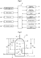
- FIG. 3 illustrates temperature changes of hot water in a tank of a hot water storage device. Specifically, FIG. 3 shows an exemplary structure of the tank 17 used to describe temperature changes of the hot water, and FIG. 4 is a graph showing temperature changes of the hot water inside of the tank 17.
- the volume of the tank 17 used is 148 L (liters).
- the hot water discharge path 9 is connected to a top portion of the tank 17.
- the water supply path 8 is connected to a side portion of the tank 17, at a position where the volume from the top portion of the tank 17 is 133 L.
- Temperature sensors T1, T2, T3, and T4 are provided at the side portion of the tank 17.
- the temperature sensor T1 is provided at a position where the volume from the top portion of the tank 17 is 33 L.
- the temperature sensor T2 is provided at a position where the volume from the top portion of the tank 17 is 61 L.
- the temperature sensor T3 is provided at a position where the volume from the top portion of the tank 17 is 93 L.
- the temperature sensor T4 is provided at a position where the volume from the top portion of the tank 17 is 125 L.
- the tank 17 is provided with the heat exchange unit 18 that performs heat exchange between the hot water and the second heat medium.
- the second heat medium flows into the heat exchange unit 18 through the second heat medium supply path 3, and the second heat medium flows out from the heat exchange unit 18 through the second heat medium return path 2.
- the second heat medium supply path 3 is connected at a position where the volume from the top portion of the tank 17 is 83 L.
- the second heat medium return path 2 is connected at a position where the volume from the top portion of the tank 17 is 131 L.
- FIG. 4 shows changes over time of temperatures (°C) of hot water measured by each of the temperature sensors T1, T2, T3, and T4, changes over time of the flow rate per unit time (L/min) of the second heat medium in the heat exchange unit 18 (indicated as “B: flow rate” in the figure), changes over time of the outflow amount (L/min) of hot water from the hot water discharge path 9 (indicated as “C: outflow amount” in the figure), and changes over time of power generation output (W) of the combined heat and power supply unit 50 (indicated as "A: power generation output” in the figure).
- the waste heat recovery unit 20 recovers heat generated by the combined heat and power supply unit 50 using the first heat medium, and transfers the recovered heat to the second heat medium, so in FIG. 4 , while the combined heat and power supply unit 50 (the combined heat and power supply device CG) is operating and the flow rate of the second heat medium in the heat exchange unit 18 is greater than zero, the heat generated by the combined heat and power supply unit 50 is transferred to the hot water inside of the tank 17.
- the combined heat and power supply unit 50 operates in a state where the power generation output is 1000 (W) and the second heat medium flows in the heat exchange unit 18, and according to this flow, the hot water inside of the tank 17 is heated by the heat generated by the combined heat and power supply unit 50.
- the temperature sensors T1, T2, T3, and T4 As a result, as indicated by the measurement results of the temperature sensors T1, T2, T3, and T4, the temperature of the entirety of hot water inside of the tank 17 increases. Thereafter, operation of the combined heat and power supply unit 50 is stopped at a time of about 86 minutes, and the flow rate of the second heat medium that flows through the heat exchange unit 18 also becomes zero.
- the temperature of the hot water measured by the temperature sensors T1, T2, T3, and T4 is about 63°C for each sensor.
- the temperature of the hot water measured by the temperature sensor T3 starts to decrease, but when operation of the combined heat and power supply unit 50 is restarted at a time of about 102 minutes and the second heat medium at a high temperature starts flowing in the heat exchange unit 18, the temperature of the hot water measured by the temperature sensors T3 and T4 starts to increase.
- FIG. 5 illustrates operation modes of the heat supply system.
- an indoor heating permitted time zone where operation of the indoor heating device 15 is permitted, and an indoor heating unpermitted time zone where operation is not permitted and that is other than the indoor heating permitted time zone, are set, and for example, this setting information is stored in the storage device 47.
- the indoor heating permitted time zone and the indoor heating unpermitted time zone are items of information input by a user or the like of the heat supply system using the input device 48, or information determined in advance with respect to the indoor heating device 15.
- two hours between the time 6:00 and the time 8:00, and six hours from the time 16:00 to the time 22:00 are the indoor heating permitted time zone, and the other time zones are the indoor heating unpermitted time zone.
- a temperature increase permitted time zone where a temperature increase operation of the hot water stored inside of the tank 17 of the hot water storage device 16 is permitted, and a temperature increase unpermitted time zone where a temperature increase operation is not permitted, are set, and for example, this setting information is stored in the storage device 47.
- the temperature increase permitted time zone and the temperature increase unpermitted time zone are items of information input by a user or the like of the heat supply system using the input device 48, or information determined in advance with respect to the hot water storage device 16.
- three hours between the time 3:00 and the time 6:00, and eight hours from the time 13:00 to the time 21:00 are the temperature increase permitted time zone, and the other time zones are the temperature increase unpermitted time zone.
- a boiler permitted time zone where operation of the boiler device 1 is permitted, and a boiler unpermitted time zone where operation of the boiler device 1 is not permitted, are set, and for example, this setting information is stored in the storage device 47.
- the boiler permitted time zone and the boiler unpermitted time zone are items of information input by a user or the like of the heat supply system using the input device 48, or information determined in advance with respect to the boiler device 1.
- two hours between the time 6:00 and the time 8:00, and six hours from the time 16:00 to the time 22:00 are the boiler permitted time zone, and the other time zones are the boiler unpermitted time zone.
- a combined heat and power supply permitted time zone where operation of the combined heat and power supply device CG is permitted, and a combined heat and power supply unpermitted time zone where operation of the combined heat and power supply device CG is not permitted are set, and for example, this setting information is stored in the storage device 47.
- the combined heat and power supply permitted time zone and the combined heat and power supply unpermitted time zone are items of information input by a user or the like of the heat supply system using the input device 48, or information determined in advance with respect to the combined heat and power supply device CG.
- the control device C operates the combined heat and power supply device CG, and operates the flow state adjustment devices (the circulation pump 44, the second pump 33, the opening/closing valve 6, and the opening/closing valve 7) such that the heat medium circulates between the combined heat and power supply device CG and the hot water storage device 16 through the second heat medium supply path 3 and the second heat medium return path 2.
- the control device C operates the combined heat and power supply device CG, and operates the flow state adjustment devices such that the heat medium circulates between the combined heat and power supply device CG and the hot water storage device 16 through the second heat medium supply path 3 and the second heat medium return path 2, thereby executing a temperature increase operation by the combined heat and power supply device CG.
- control device C operates the internal combustion engine 52 and the generator 51 included in the combined heat and power supply device CG, operates the first pump 32 and the second pump 33 included in the waste heat recovery unit 20, operates the circulation pump 44, and opens the opening/closing valve 6.
- the heat generated by the combined heat and power supply unit 50 is transferred to the first heat medium, and the heat held by the first heat medium is transferred to the second heat medium.
- the second heat medium passes through the second heat medium supply path 3 and is supplied to the heat exchange unit 18 of the hot water storage device 16, and thus the temperature of the hot water inside of the tank 17 is increased.
- the control device C does not operate the combined heat and power supply unit 50 and the waste heat recovery unit 20.
- the control device C does not operate the combined heat and power supply unit 50 and the waste heat recovery unit 20.
- the control device C operates the boiler device 1, and operates the flow state adjustment devices (the circulation pump 44, the second pump 33, the opening/closing valve 6, and the opening/closing valve 7) such that the heat medium circulates between the boiler device 1 and the hot water storage device 16 through the second heat medium supply path 3 and the second heat medium return path 2.
- the control device C when the current time is in the temperature increase permitted time zone and the boiler permitted time zone, and the second temperature (the temperature of the hot water measured by the second temperature sensor 45) of the hot water inside of the tank 17 of the hot water storage device 16 to be heated is the second lower limit temperature or less, where a temperature increase operation by the boiler device 1 is permitted, the control device C operates the boiler device 1, and operates the flow state adjustment devices such that the heat medium circulates between the boiler device 1 and the hot water storage device 16 through the second heat medium supply path 3 and the second heat medium return path 2, thereby executing a temperature increase operation by the boiler device 1. That is, the control device C operates the boiler device 1, operates the circulation pump 44, and opens the opening/closing valve 6.
- the heat generated by the boiler device 1 is transferred to the second heat medium.
- the second heat medium passes through the second heat medium supply path 3 and is supplied to the heat exchange unit 18 of the hot water storage device 16, and thus the temperature of the hot water inside of the tank 17 is increased.
- the control device C does not operate the boiler device 1.
- the above first temperature measured by the first temperature sensor 46 is the temperature of the hot water stored relatively lower inside the tank 17 than the hot water of the second temperature measured by the second temperature sensor 45. That is, relatively low temperature hot water exists in the lower portion of the tank 17 as described above, and a state in which relatively high temperature hot water exists in the upper portion of the tank 17 appears first as a temperature decrease of the hot water at the temperature detection location of the first temperature sensor 46, which is lower than the second temperature sensor 45.
- the first lower limit temperature is a temperature that is the second lower limit temperature or more, and for example, the first lower limit temperature is 55°C and the second lower limit temperature is 30°C.
- the first temperature is 55°C (the first lower limit temperature) or less. That is, even when the current time is in the temperature increase permitted time zone, the combined heat and power supply permitted time zone, and the boiler permitted time zone, that is, even when the combined heat and power supply device CG can be operated based on the value of the first temperature and the boiler device 1 can be operated based on the value of the second temperature, the first temperature becomes the first lower limit temperature or less before the second temperature becomes the second lower limit temperature or less, so operation is started first for the combined heat and power supply device CG.
- the control device C is executing a temperature increase operation by the combined heat and power supply device CG, if the first temperature of the hot water stored inside of the tank 17 of the hot water storage device 16 becomes a first upper limit temperature or more (for example, 60°C or more), where a temperature increase operation by the combined heat and power supply device CG is not permitted, the control device C stops the combined heat and power supply device CG.
- a first upper limit temperature or more for example, 60°C or more
- a configuration may be adopted in which the control device C, when stopping the combined heat and power supply device CG, operates the flow state adjustment devices (the circulation pump 44, the second pump 33, the opening/closing valve 6, and the opening/closing valve 7) such that the heat medium does not circulate between the combined heat and power supply device CG and the hot water storage device 16, or operates the flow state adjustment devices (the circulation pump 44, the second pump 33, the opening/closing valve 6, and the opening/closing valve 7) such that the heat medium continuously circulates between the combined heat and power supply device CG and the hot water storage device 16.
- the control device C when stopping the combined heat and power supply device CG, operates the flow state adjustment devices (the circulation pump 44, the second pump 33, the opening/closing valve 6, and the opening/closing valve 7) such that the heat medium does not circulate between the combined heat and power supply device CG and the hot water storage device 16, or operates the flow state adjustment devices (the circulation pump 44, the second pump 33, the opening/closing valve 6, and the
- the control device C when the current time is in the temperature increase permitted time zone and the boiler permitted time zone, while the control device C is executing a temperature increase operation by the boiler device 1, if the second temperature of the hot water stored inside of the tank 17 of the hot water storage device 16 becomes a second upper limit temperature or more (for example, 45°C or more), where a temperature increase operation by the boiler device 1 is not permitted, the control device C stops the boiler device 1.
- a configuration may be adopted in which the control device C, when stopping the boiler device 1, operates the flow state adjustment devices such that the heat medium does not circulate between the boiler device 1 and the hot water storage device 16, or operates the flow state adjustment devices such that the heat medium continuously circulates between the boiler device 1 and the hot water storage device 16.
- the first upper limit temperature (60°C) is set to a higher temperature than the first lower limit temperature (55°C)
- the second upper limit temperature (45°C) is set to a higher temperature than the second lower limit temperature (30°C)
- the first upper limit temperature (60°C) is set to a higher temperature than the second upper limit temperature (45°C).
- the second temperature can be expected to reach the second upper limit temperature before the first temperature reaches the first upper limit temperature. That is, even if both the combined heat and power supply device CG and the boiler device 1 are operated to increase temperature, the boiler device 1 can be expected to stop first.
- the combined heat and power supply device CG which has high energy efficiency, is utilized for a temperature increase operation of the hot water for a longer period.
- the temperature increase permitted time zone in one day there is at least one individual temperature increase time zone that is continuous in time.
- two individual temperature increase time zones are set in one day, with one individual temperature increase time zone being three hours from the time 3:00 to the time 6:00, and another individual temperature increase time zone being eight hours from the time 13:00 to the time 21:00.
- the individual temperature increase time zone from the time 3:00 to the time 6:00 overlaps in time with the combined heat and power supply permitted time zone, and is set so as to not overlap in time with the boiler permitted time zone.
- a temperature increase operation of the hot water storage device 16 can only be performed with the heat generated by the combined heat and power supply device CG. That is, it is possible to lengthen the operation time of the combined heat and power supply device CG.
- a partial time zone (from the time 13:00 to the time 16:00) including the start time of that zone overlaps in time with the combined heat and power supply permitted time zone, and is set so as to not overlap in time with the boiler permitted time zone.
- a time zone (from the time 16:00 to the time 21:00) after that partial time zone is set so as to overlap in time with the combined heat and power supply permitted time zone and the boiler permitted time zone.
- both the heat generated by the combined heat and power supply device CG and the heat generated by the boiler device 1 can be used in the temperature increase operation of the hot water storage device 16.
- the heat generated by the boiler device 1 can also be utilized in the temperature increase operation of the hot water storage device 16.
- a temperature increase of the air inside a building B can be performed by the indoor heating device 15 utilizing the heat generated by the combined heat and power supply device CG.
- the control device C operates the combined heat and power supply device CG, and operates the flow state adjustment devices (the circulation pump 44, the second pump 33, the opening/closing valve 6, and the opening/closing valve 7) such that the heat medium circulates between the combined heat and power supply device CG and the indoor heating device 15 through the second heat medium supply path 3 and the second heat medium return path 2,
- control device C operates the internal combustion engine 52 and the generator 51 included in the combined heat and power supply unit 50, operates the first pump 32 and the second pump 33 included in the waste heat recovery unit 20, operates the circulation pump 44, and opens the opening/closing valve 7.
- the heat generated by the combined heat and power supply unit 50 is transferred to the first heat medium, and further, the heat held by the first heat medium is transferred to the second heat medium.
- the second heat medium passes through the second heat medium supply path 3 and is supplied to the indoor heating device 15, and thus heat radiation of the second heat medium by the indoor heating device 15 (indoor heating) is performed.
- the control device C is executing an indoor heating operation utilizing the combined heat and power supply device CG, if the temperature of the air measured by the room temperature sensor 49 satisfies a temperature condition where an indoor heating operation utilizing the combined heat and power supply device CG is not permitted, that is, the air temperature becomes a third upper limit temperature (for example, such as 24°C) or more, where an indoor heating operation utilizing the combined heat and power supply device CG is not permitted, the control device C stops the combined heat and power supply device CG. Thus, operation of the indoor heating device 15 is substantially stopped.
- a third upper limit temperature for example, such as 24°C
- control device C when stopping the combined heat and power supply device CG, operates the flow state adjustment devices such that the heat medium does not circulate between the combined heat and power supply device CG and the indoor heating device 15, or operates the flow state adjustment devices such that the heat medium continuously circulates between the combined heat and power supply device CG and the indoor heating device 15.
- the control device C does not operate the indoor heating device 15.
- a temperature increase of the air inside the building B can be performed by the indoor heating device 15 using the heat generated by the boiler device 1.
- the control device C operates the boiler device 1, and operates the flow state adjustment devices (the circulation pump 44, the second pump 33, the opening/closing valve 6, and the opening/closing valve 7) such that the heat medium circulates between the boiler device 1 and the indoor heating device 15 through the second heat medium supply path 3 and the second heat medium return path 2, thereby executing an indoor heating operation using the boiler device 1.
- control device C operates the boiler device 1, operates the circulation pump 44, and opens the opening/closing valve 7.
- the heat generated by the boiler device 1 is transferred to the second heat medium.
- the second heat medium passes through the second heat medium supply path 3 and is supplied to the indoor heating device 15, and thus heat radiation of the second heat medium by the indoor heating device 15 (indoor heating) is performed.
- the third lower limit temperature (22°C) is set to a higher temperature than the fourth lower limit temperature (20°C). That is, even when the current time is in the indoor heating permitted time zone, the combined heat and power supply permitted time zone, and the boiler permitted time zone, that is, even when the combined heat and power supply device CG can be operated based on the value of the air temperature and the boiler device 1 can be operated based on the value of the air temperature, the air temperature reaches the third lower limit temperature or less before the air temperature reaches the fourth lower limit temperature or less, so the combined heat and power supply device CG is utilized first for indoor heating operation.
- the control device C does not operate the indoor heating device 15.
- the control device C does not operate the indoor heating device 15.
- the control device C is executing an indoor heating operation utilizing the boiler device 1 if the temperature of the air measured by the room temperature sensor 49 satisfies a temperature condition where an indoor heating operation utilizing the boiler device 1 is not permitted, that is, the air temperature becomes a fourth upper limit temperature (for example, such as 21°C) or more, where an indoor heating operation utilizing the boiler device 1 is not permitted, the control device C stops the boiler device 1. Thus, operation of the indoor heating device 15 is substantially stopped.
- a fourth upper limit temperature for example, such as 21°C
- control device C when stopping the boiler device 1, operates the flow state adjustment devices such that the heat medium does not circulate between the boiler device 1 and the indoor heating device 15, or operates the flow state adjustment devices such that the heat medium continuously circulates between the boiler device 1 and the indoor heating device 15.
- the third upper limit temperature (24°C) is set to a higher temperature than the third lower limit temperature (22°C)
- the fourth upper limit temperature (21°C) is set to a higher temperature than the fourth lower limit temperature (20°C)
- the third upper limit temperature (24°C) is set to a temperature of the fourth upper limit temperature (21°C) or more.
- the indoor heating permitted time zone there is at least one individual indoor heating time zone that is continuous in time in one day.
- two individual indoor heating time zones are set in one day, with one individual indoor heating time zone being two hours from the time 6:00 to the time 8:00, and another individual indoor heating time zone being six hours from the time 16:00 to the time 22:00.
- the individual indoor heating time zone from the time 6:00 to the time 8:00, and the individual indoor heating time zone from the time 16:00 to the time 22:00, are both set to overlap in time with a combined heat and power supply permitted time zone and a boiler permitted time zone.
- both the heat generated by the combined heat and power supply device CG and the heat generated by the boiler device 1 can be utilized in the indoor heating operation of the indoor heating device 15.
- the second heat medium supply path 3 and the second heat medium return path 2 are shared by the boiler device 1 and the combined heat and power supply device CG, and the indoor heating device 15 and the hot water storage device 16, so when indoor heating operation of the indoor heating device 15 by the boiler device 1 and hot water storage operation of the hot water storage device 16 by the combined heat and power supply device CG are performed in the same time zone, hot water storage operation of the hot water storage device 16 by the boiler device 1 and indoor heating operation of the indoor heating device 15 by the combined heat and power supply device CG are performed unintentionally.
- the time zone from the time 6:00 to the time 8:00, in which indoor heating operation of the indoor heating device 15 by the boiler device 1 can be performed is set so as to not overlap in time with the time zone from the time 3:00 to the time 6:00, in which hot water storage operation of the hot water storage device 16 by the combined heat and power supply device CG can be performed.
- a heat supply system of a second embodiment differs from the above-described embodiment in that operation control of the combined heat and power supply device CG and operation control of the boiler device 1 are performed using one temperature sensor. Following is a description of the heat supply system of the second embodiment, but a description of the same configurations as in the above embodiment will be omitted here.
- operation control of the combined heat and power supply device CG and operation control of the boiler device 1 are performed using a plurality of temperature sensors (the first temperature sensor 46 and the second temperature sensor 45), but in the present embodiment, operation control of the combined heat and power supply device CG and operation control of the boiler device 1 are performed using one temperature sensor. Specifically, any one of the first temperature sensor 46 and the second temperature sensor 45 described above is used.
- the first temperature sensor 46 is used as a temperature sensor that measures the temperature of hot water stored in a tank
- the second temperature sensor 45 may also be used as a temperature sensor that measures the temperature of hot water stored in a tank.
- the control device C when the first temperature of the hot water measured by the first temperature sensor 46 is the first lower limit temperature or less, where a temperature increase operation by the combined heat and power supply device CG is permitted, the control device C operates the combined heat and power supply device CG, and operates the flow state adjustment devices (the circulation pump 44, the second pump 33, the opening/closing valve 6, and the opening/closing valve 7) such that the heat medium circulates between the combined heat and power supply device CG and the hot water storage device 16 through the second heat medium supply path 3 and the second heat medium return path 2, and also, when the second temperature of the hot water measured by the first temperature sensor 46 is the second lower limit temperature or less, where a temperature increase operation by the boiler device 1 is permitted, the control device C operates the boiler device 1, and operates the flow state adjustment devices such that the heat medium circulates between the boiler device 1 and the hot water storage device 16 through the second heat medium supply path 3 and the second heat medium return path 2.
- the first lower limit temperature is a temperature higher than the second lower limit temperature.
- the first lower limit temperature is a temperature such as 55°C
- the second lower limit temperature is a temperature such as 30°C.
- the first lower limit temperature which is a reference temperature at the time of starting operation of the combined heat and power supply device CG
- the second lower limit temperature which is a reference temperature at the time of starting operation of the boiler device 1.
- the temperature of the hot water measured by the first temperature sensor 46 reaches the first lower limit temperature or less earlier in time than the temperature of the hot water measured by the first temperature sensor 46 reaches the second lower limit temperature or less.
- a temperature increase operation of the hot water is started earlier for the combined heat and power supply device CG, which has high energy efficiency, than for the boiler device 1.
- the boiler device 1 with a large heat output is operated in addition to the combined heat and power supply device CG to increase the temperature of the hot water.
- the control device C while the control device C is executing a temperature increase operation by the combined heat and power supply device CG, if the temperature of the hot water measured by the first temperature sensor 46 (the first temperature) becomes the first upper limit temperature or more (for example, 60°C or more), where a temperature increase operation by the combined heat and power supply device CG is not permitted, the control device C stops the combined heat and power supply device CG.
- a configuration may be adopted in which the control device C, when stopping the combined heat and power supply device CG, operates the flow state adjustment devices (the circulation pump 44, the second pump 33, the opening/closing valve 6, and the opening/closing valve 7) such that the heat medium does not circulate between the combined heat and power supply device CG and the hot water storage device 16, or operates the flow state adjustment devices such that the heat medium continuously circulates between the combined heat and power supply device CG and the hot water storage device 16.
- the control device C when stopping the combined heat and power supply device CG, operates the flow state adjustment devices (the circulation pump 44, the second pump 33, the opening/closing valve 6, and the opening/closing valve 7) such that the heat medium does not circulate between the combined heat and power supply device CG and the hot water storage device 16, or operates the flow state adjustment devices such that the heat medium continuously circulates between the combined heat and power supply device CG and the hot water storage device 16.
- the control device C while the control device C is executing a temperature increase operation by the boiler device 1, if the temperature of the hot water measured by the first temperature sensor 46 (the second temperature) becomes the second upper limit temperature or more (for example, 45°C or more), where a temperature increase operation by the boiler device 1 is not permitted, the control device C stops the boiler device 1.
- the control device C when stopping the boiler device 1, operates the flow state adjustment devices such that the heat medium does not circulate between the boiler device 1 and the hot water storage device 16, or operates the flow state adjustment devices such that the heat medium continuously circulates between the boiler device 1 and the hot water storage device 16.
- the first upper limit temperature (60°C) is set to a higher temperature than the first lower limit temperature (55°C)
- the second upper limit temperature (45°C) is set to a higher temperature than the second lower limit temperature (30°C)
- the first lower limit temperature (55°C) is set to a higher temperature than the second lower limit temperature (30°C)
- the first upper limit temperature (60°C) is set to a higher temperature than the second upper limit temperature (45°C).
- a temperature difference (5°C) is provided between the first upper limit temperature (60°C) and the first lower limit temperature (55°C)
- a temperature difference (15°C) is provided between the second upper limit temperature (45°C) and the second lower limit temperature (30°C). That is, the temperature difference (5°C) between the first upper limit temperature and the first lower limit temperature is set smaller than the temperature difference (15°C) between the second upper limit temperature (45°C) and the second lower limit temperature (30°C).
- operation of the combined heat and power supply device CG can be started at an early stage if the temperature of the hot water inside of the tank 17 of the hot water storage device 16 decreases slightly, this operation continues until the temperature of the hot water reaches a relatively high temperature, operation of the boiler device 1 does not start until the temperature of the hot water inside of the tank 17 decreases greatly, and this operation is stopped as soon as possible.
- the first temperature sensor (the first temperature detection unit) 46, the second temperature sensor (the second temperature detection unit) 45, the room temperature sensor (the room temperature detection unit) 49, and the like may also be realized with a thermostat.
- the first temperature detection unit which is a thermostat
- the control device C can know that the first temperature detection unit, which is a thermostat, has detected that the temperature of the hot water has become the first lower limit temperature or less.
- a threshold temperature for example, such as the above-described first lower limit temperature
- the mixer 34 may be configured using an electronically controlled three-way mixing valve with valve opening/closing adjustment controlled according to a temperature detected by a temperature sensor (not shown), for example, or the mixer 34 may be configured using a plurality of such electronically controlled two-way valves.
- the present invention can be utilized in a heat supply system capable of efficiently operating a plurality of heat source devices according to the state of a heat utilization device.
Landscapes
- Engineering & Computer Science (AREA)
- Chemical & Material Sciences (AREA)
- Combustion & Propulsion (AREA)
- Mechanical Engineering (AREA)
- General Engineering & Computer Science (AREA)
- Physics & Mathematics (AREA)
- Thermal Sciences (AREA)
- Water Supply & Treatment (AREA)
- Heat-Pump Type And Storage Water Heaters (AREA)
Applications Claiming Priority (2)
| Application Number | Priority Date | Filing Date | Title |
|---|---|---|---|
| JP2015008804A JP6452465B2 (ja) | 2015-01-20 | 2015-01-20 | 熱供給システム |
| PCT/JP2015/082714 WO2016117220A1 (fr) | 2015-01-20 | 2015-11-20 | Système d'apport de chaleur |
Publications (3)
| Publication Number | Publication Date |
|---|---|
| EP3249314A1 true EP3249314A1 (fr) | 2017-11-29 |
| EP3249314A4 EP3249314A4 (fr) | 2018-10-10 |
| EP3249314B1 EP3249314B1 (fr) | 2021-05-19 |
Family
ID=56416780
Family Applications (1)
| Application Number | Title | Priority Date | Filing Date |
|---|---|---|---|
| EP15878909.9A Active EP3249314B1 (fr) | 2015-01-20 | 2015-11-20 | Système d'apport de chaleur |
Country Status (6)
| Country | Link |
|---|---|
| US (1) | US10544945B2 (fr) |
| EP (1) | EP3249314B1 (fr) |
| JP (1) | JP6452465B2 (fr) |
| CA (1) | CA2974322C (fr) |
| DK (1) | DK3249314T3 (fr) |
| WO (1) | WO2016117220A1 (fr) |
Cited By (1)
| Publication number | Priority date | Publication date | Assignee | Title |
|---|---|---|---|---|
| EP4269882A1 (fr) * | 2022-04-25 | 2023-11-01 | Gebr. Kemper GmbH + Co. KG | Système d'alimentation en eau chaude avec récupération de chaleur |
Families Citing this family (3)
| Publication number | Priority date | Publication date | Assignee | Title |
|---|---|---|---|---|
| CN110397982A (zh) * | 2019-07-31 | 2019-11-01 | 中如建筑工程(上海)有限公司 | 一种用于供暖的高压电极锅炉水蓄热系统 |
| CN114183807B (zh) * | 2021-11-25 | 2023-04-18 | 广西电网有限责任公司电力科学研究院 | 一种二次加热的汽轮发电机组抽汽供热调控方法 |
| CN114608066B (zh) * | 2022-04-26 | 2023-09-05 | 珠海格力电器股份有限公司 | 供热控制方法、装置、供热系统和电子设备 |
Family Cites Families (34)
| Publication number | Priority date | Publication date | Assignee | Title |
|---|---|---|---|---|
| US2211573A (en) * | 1938-01-13 | 1940-08-13 | Honeywell Regulator Co | Heating system |
| US4451003A (en) * | 1983-06-09 | 1984-05-29 | Exxon Research And Engineering Co. | Control scheme and apparatus for a cogeneration boiler |
| US4754607A (en) * | 1986-12-12 | 1988-07-05 | Allied-Signal Inc. | Power generating system |
| JPH02126051A (ja) * | 1988-11-05 | 1990-05-15 | Yanmar Diesel Engine Co Ltd | ヒートポンプ式給湯装置の運転制御方法 |
| US5020721A (en) * | 1989-09-19 | 1991-06-04 | Gas Fired Products | Rapid recovery gas hot water heater |
| JP2000205044A (ja) * | 1999-01-19 | 2000-07-25 | Shigeaki Kimura | コ―ジェネレ―ション装置 |
| JP3620701B2 (ja) | 1999-04-14 | 2005-02-16 | 本田技研工業株式会社 | コジェネレーション装置 |
| JP2001132539A (ja) * | 1999-11-01 | 2001-05-15 | Honda Motor Co Ltd | エンジンの排熱回収装置 |
| JP2002022280A (ja) * | 2000-07-03 | 2002-01-23 | Osaka Gas Co Ltd | 貯湯式給湯システム |
| JP2002277053A (ja) * | 2001-03-15 | 2002-09-25 | Takenaka Komuten Co Ltd | コージェネレーションシステムの温水回収制御装置 |
| JP3742356B2 (ja) * | 2002-03-20 | 2006-02-01 | 株式会社日立製作所 | ヒートポンプ給湯機 |
| US7493775B2 (en) * | 2002-10-30 | 2009-02-24 | Mitsubishi Denki Kabushiki Kaisha | Air conditioner |
| JP4649897B2 (ja) * | 2004-07-09 | 2011-03-16 | ダイキン工業株式会社 | 熱搬送システム |
| JP2006083720A (ja) * | 2004-09-14 | 2006-03-30 | Honda Motor Co Ltd | コジェネレーション装置 |
| KR100644830B1 (ko) * | 2004-12-10 | 2006-11-15 | 엘지전자 주식회사 | 열병합 발전 시스템 |
| KR100638223B1 (ko) * | 2005-06-16 | 2006-10-27 | 엘지전자 주식회사 | 열병합 발전 시스템 |
| KR100755322B1 (ko) * | 2005-07-08 | 2007-09-05 | 엘지전자 주식회사 | 열병합 발전시스템 및 그의 전력제어방법 |
| KR100634810B1 (ko) * | 2005-07-12 | 2006-10-16 | 엘지전자 주식회사 | 열병합 발전 시스템 |
| KR101270614B1 (ko) * | 2006-07-25 | 2013-06-07 | 엘지전자 주식회사 | 코제너레이션 |
| KR101270615B1 (ko) * | 2006-07-25 | 2013-06-07 | 엘지전자 주식회사 | 코제너레이션 및 그 제어 방법 |
| KR101270616B1 (ko) * | 2006-07-27 | 2013-06-07 | 엘지전자 주식회사 | 코제너레이션 |
| US8245949B2 (en) * | 2007-07-25 | 2012-08-21 | Grand Hotel, LLC | Energy conservation system for using heat from air conditioning units to heat water supply lines |
| US8479689B2 (en) * | 2008-07-10 | 2013-07-09 | Heat-Timer Corporation | Optimizing multiple boiler plant systems with mixed condensing and non-condensing boilers |
| US8515584B2 (en) * | 2009-08-20 | 2013-08-20 | Transformative Wave Technologies Llc | Energy reducing retrofit method for a constant volume HVAC system |
| US8849462B2 (en) * | 2009-12-02 | 2014-09-30 | Velvetwire Llc | Method and apparatus for automation of a programmable device |
| US8950687B2 (en) * | 2010-09-21 | 2015-02-10 | Honeywell International Inc. | Remote control of an HVAC system that uses a common temperature setpoint for both heat and cool modes |
| US8843238B2 (en) * | 2011-09-30 | 2014-09-23 | Johnson Controls Technology Company | Systems and methods for controlling energy use in a building management system using energy budgets |
| JP2013104596A (ja) | 2011-11-11 | 2013-05-30 | Mitsubishi Heavy Ind Ltd | 温水暖房・給湯システム |
| JP5875907B2 (ja) * | 2012-03-15 | 2016-03-02 | 東邦瓦斯株式会社 | 給湯暖房システム |
| GB201208519D0 (en) * | 2012-05-15 | 2012-06-27 | Passivsystems Ltd | Predictive temperature management system controller |
| US20150204577A1 (en) | 2012-09-28 | 2015-07-23 | Kyungdong Navien Co., Ltd. | Structure for controlling temperature of hot-water supply from waste heat recovery system using three-way valve or mixing valve, and structure for controlling temperature of hot-water supply from waste heat recovery system using heat exchanger in hot-water tank |
| ITPD20130186A1 (it) * | 2013-07-02 | 2015-01-03 | Sit La Precisa S P A Con Socio Uni Co | Metodo di controllo del funzionamento di un bruciatore |
| WO2016071947A1 (fr) * | 2014-11-04 | 2016-05-12 | 三菱電機株式会社 | Dispositif de cycle de réfrigération et système de détection d'anomalie dans un dispositif de cycle de réfrigération |
| US9760501B2 (en) * | 2014-11-05 | 2017-09-12 | Google Inc. | In-field smart device updates |
-
2015
- 2015-01-20 JP JP2015008804A patent/JP6452465B2/ja active Active
- 2015-11-20 US US15/544,322 patent/US10544945B2/en active Active
- 2015-11-20 WO PCT/JP2015/082714 patent/WO2016117220A1/fr not_active Ceased
- 2015-11-20 DK DK15878909.9T patent/DK3249314T3/da active
- 2015-11-20 CA CA2974322A patent/CA2974322C/fr active Active
- 2015-11-20 EP EP15878909.9A patent/EP3249314B1/fr active Active
Cited By (1)
| Publication number | Priority date | Publication date | Assignee | Title |
|---|---|---|---|---|
| EP4269882A1 (fr) * | 2022-04-25 | 2023-11-01 | Gebr. Kemper GmbH + Co. KG | Système d'alimentation en eau chaude avec récupération de chaleur |
Also Published As
| Publication number | Publication date |
|---|---|
| US10544945B2 (en) | 2020-01-28 |
| DK3249314T3 (da) | 2021-06-21 |
| CA2974322C (fr) | 2023-04-04 |
| EP3249314A4 (fr) | 2018-10-10 |
| US20180010809A1 (en) | 2018-01-11 |
| CA2974322A1 (fr) | 2016-07-28 |
| JP6452465B2 (ja) | 2019-01-16 |
| EP3249314B1 (fr) | 2021-05-19 |
| JP2016133271A (ja) | 2016-07-25 |
| WO2016117220A1 (fr) | 2016-07-28 |
Similar Documents
| Publication | Publication Date | Title |
|---|---|---|
| US9885484B2 (en) | Multi-tank water heater systems | |
| US20140202549A1 (en) | Multi-tank water heater systems | |
| JP5097624B2 (ja) | 温水供給システム | |
| US10408164B2 (en) | Waste heat recovery device, heat supply system, and operation method for waste heat recovery device | |
| JP5171410B2 (ja) | 温水供給システム | |
| US10544945B2 (en) | Heat supply system | |
| JP5828219B2 (ja) | コージェネレーションシステム、排熱利用装置、コージェネレーションシステムの制御方法及びヒートポンプ式給湯装置 | |
| JP2018031520A (ja) | 貯湯給湯装置 | |
| JP6635809B2 (ja) | 排熱利用熱源設備 | |
| JP6390903B2 (ja) | 貯湯給湯システム | |
| JP6771343B2 (ja) | 熱供給システム | |
| JP6331461B2 (ja) | 給湯暖房装置 | |
| JP5921416B2 (ja) | コージェネレーションシステム及び給湯設備 | |
| JP6672983B2 (ja) | 貯湯給湯装置 | |
| JP6015924B2 (ja) | 貯湯給湯システム | |
| JP5625683B2 (ja) | 温水システムの制御装置 | |
| JP2018071822A (ja) | 給湯装置 | |
| JP2015155780A (ja) | コージェネ装置 | |
| JP5541999B2 (ja) | 熱供給設備 | |
| WO2017110900A1 (fr) | Système d'alimentation en chaleur | |
| JP2015158323A (ja) | コージェネレーションシステム | |
| JP2006078173A (ja) | 給湯システム | |
| JP2015059681A (ja) | 貯湯給湯装置 | |
| JP2005180805A (ja) | 排熱回収給湯暖房装置 | |
| WO2016117221A1 (fr) | Dispositif de récupération de chaleur d'échappement, système d'apport de chaleur et procédé de fonctionnement pour dispositif de récupération de chaleur d'échappement |
Legal Events
| Date | Code | Title | Description |
|---|---|---|---|
| STAA | Information on the status of an ep patent application or granted ep patent |
Free format text: STATUS: THE INTERNATIONAL PUBLICATION HAS BEEN MADE |
|
| PUAI | Public reference made under article 153(3) epc to a published international application that has entered the european phase |
Free format text: ORIGINAL CODE: 0009012 |
|
| STAA | Information on the status of an ep patent application or granted ep patent |
Free format text: STATUS: REQUEST FOR EXAMINATION WAS MADE |
|
| 17P | Request for examination filed |
Effective date: 20170801 |
|
| AK | Designated contracting states |
Kind code of ref document: A1 Designated state(s): AL AT BE BG CH CY CZ DE DK EE ES FI FR GB GR HR HU IE IS IT LI LT LU LV MC MK MT NL NO PL PT RO RS SE SI SK SM TR |
|
| AX | Request for extension of the european patent |
Extension state: BA ME |
|
| DAV | Request for validation of the european patent (deleted) | ||
| DAX | Request for extension of the european patent (deleted) | ||
| REG | Reference to a national code |
Ref country code: DE Ref legal event code: R079 Ref document number: 602015069576 Country of ref document: DE Free format text: PREVIOUS MAIN CLASS: F24H0001000000 Ipc: F02G0005040000 |
|
| A4 | Supplementary search report drawn up and despatched |
Effective date: 20180910 |
|
| RIC1 | Information provided on ipc code assigned before grant |
Ipc: F24D 3/08 20060101ALI20180904BHEP Ipc: F24D 17/00 20060101ALI20180904BHEP Ipc: F24D 12/02 20060101ALI20180904BHEP Ipc: F02G 5/04 20060101AFI20180904BHEP Ipc: F24D 19/10 20060101ALI20180904BHEP |
|
| STAA | Information on the status of an ep patent application or granted ep patent |
Free format text: STATUS: EXAMINATION IS IN PROGRESS |
|
| 17Q | First examination report despatched |
Effective date: 20200127 |
|
| GRAP | Despatch of communication of intention to grant a patent |
Free format text: ORIGINAL CODE: EPIDOSNIGR1 |
|
| STAA | Information on the status of an ep patent application or granted ep patent |
Free format text: STATUS: GRANT OF PATENT IS INTENDED |
|
| INTG | Intention to grant announced |
Effective date: 20201223 |
|
| GRAS | Grant fee paid |
Free format text: ORIGINAL CODE: EPIDOSNIGR3 |
|
| GRAA | (expected) grant |
Free format text: ORIGINAL CODE: 0009210 |
|
| STAA | Information on the status of an ep patent application or granted ep patent |
Free format text: STATUS: THE PATENT HAS BEEN GRANTED |
|
| AK | Designated contracting states |
Kind code of ref document: B1 Designated state(s): AL AT BE BG CH CY CZ DE DK EE ES FI FR GB GR HR HU IE IS IT LI LT LU LV MC MK MT NL NO PL PT RO RS SE SI SK SM TR |
|
| REG | Reference to a national code |
Ref country code: GB Ref legal event code: FG4D |
|
| REG | Reference to a national code |
Ref country code: CH Ref legal event code: EP |
|
| REG | Reference to a national code |
Ref country code: DE Ref legal event code: R096 Ref document number: 602015069576 Country of ref document: DE |
|
| REG | Reference to a national code |
Ref country code: AT Ref legal event code: REF Ref document number: 1394197 Country of ref document: AT Kind code of ref document: T Effective date: 20210615 |
|
| REG | Reference to a national code |
Ref country code: DK Ref legal event code: T3 Effective date: 20210614 |
|
| REG | Reference to a national code |
Ref country code: IE Ref legal event code: FG4D |
|
| REG | Reference to a national code |
Ref country code: NL Ref legal event code: FP |
|
| REG | Reference to a national code |
Ref country code: LT Ref legal event code: MG9D |
|
| PG25 | Lapsed in a contracting state [announced via postgrant information from national office to epo] |
Ref country code: LT Free format text: LAPSE BECAUSE OF FAILURE TO SUBMIT A TRANSLATION OF THE DESCRIPTION OR TO PAY THE FEE WITHIN THE PRESCRIBED TIME-LIMIT Effective date: 20210519 Ref country code: FI Free format text: LAPSE BECAUSE OF FAILURE TO SUBMIT A TRANSLATION OF THE DESCRIPTION OR TO PAY THE FEE WITHIN THE PRESCRIBED TIME-LIMIT Effective date: 20210519 Ref country code: BG Free format text: LAPSE BECAUSE OF FAILURE TO SUBMIT A TRANSLATION OF THE DESCRIPTION OR TO PAY THE FEE WITHIN THE PRESCRIBED TIME-LIMIT Effective date: 20210819 Ref country code: HR Free format text: LAPSE BECAUSE OF FAILURE TO SUBMIT A TRANSLATION OF THE DESCRIPTION OR TO PAY THE FEE WITHIN THE PRESCRIBED TIME-LIMIT Effective date: 20210519 |
|
| PG25 | Lapsed in a contracting state [announced via postgrant information from national office to epo] |
Ref country code: PT Free format text: LAPSE BECAUSE OF FAILURE TO SUBMIT A TRANSLATION OF THE DESCRIPTION OR TO PAY THE FEE WITHIN THE PRESCRIBED TIME-LIMIT Effective date: 20210920 Ref country code: NO Free format text: LAPSE BECAUSE OF FAILURE TO SUBMIT A TRANSLATION OF THE DESCRIPTION OR TO PAY THE FEE WITHIN THE PRESCRIBED TIME-LIMIT Effective date: 20210819 Ref country code: PL Free format text: LAPSE BECAUSE OF FAILURE TO SUBMIT A TRANSLATION OF THE DESCRIPTION OR TO PAY THE FEE WITHIN THE PRESCRIBED TIME-LIMIT Effective date: 20210519 Ref country code: RS Free format text: LAPSE BECAUSE OF FAILURE TO SUBMIT A TRANSLATION OF THE DESCRIPTION OR TO PAY THE FEE WITHIN THE PRESCRIBED TIME-LIMIT Effective date: 20210519 Ref country code: SE Free format text: LAPSE BECAUSE OF FAILURE TO SUBMIT A TRANSLATION OF THE DESCRIPTION OR TO PAY THE FEE WITHIN THE PRESCRIBED TIME-LIMIT Effective date: 20210519 Ref country code: LV Free format text: LAPSE BECAUSE OF FAILURE TO SUBMIT A TRANSLATION OF THE DESCRIPTION OR TO PAY THE FEE WITHIN THE PRESCRIBED TIME-LIMIT Effective date: 20210519 Ref country code: GR Free format text: LAPSE BECAUSE OF FAILURE TO SUBMIT A TRANSLATION OF THE DESCRIPTION OR TO PAY THE FEE WITHIN THE PRESCRIBED TIME-LIMIT Effective date: 20210820 Ref country code: IS Free format text: LAPSE BECAUSE OF FAILURE TO SUBMIT A TRANSLATION OF THE DESCRIPTION OR TO PAY THE FEE WITHIN THE PRESCRIBED TIME-LIMIT Effective date: 20210919 |
|
| PG25 | Lapsed in a contracting state [announced via postgrant information from national office to epo] |
Ref country code: SM Free format text: LAPSE BECAUSE OF FAILURE TO SUBMIT A TRANSLATION OF THE DESCRIPTION OR TO PAY THE FEE WITHIN THE PRESCRIBED TIME-LIMIT Effective date: 20210519 Ref country code: SK Free format text: LAPSE BECAUSE OF FAILURE TO SUBMIT A TRANSLATION OF THE DESCRIPTION OR TO PAY THE FEE WITHIN THE PRESCRIBED TIME-LIMIT Effective date: 20210519 Ref country code: EE Free format text: LAPSE BECAUSE OF FAILURE TO SUBMIT A TRANSLATION OF THE DESCRIPTION OR TO PAY THE FEE WITHIN THE PRESCRIBED TIME-LIMIT Effective date: 20210519 Ref country code: CZ Free format text: LAPSE BECAUSE OF FAILURE TO SUBMIT A TRANSLATION OF THE DESCRIPTION OR TO PAY THE FEE WITHIN THE PRESCRIBED TIME-LIMIT Effective date: 20210519 Ref country code: RO Free format text: LAPSE BECAUSE OF FAILURE TO SUBMIT A TRANSLATION OF THE DESCRIPTION OR TO PAY THE FEE WITHIN THE PRESCRIBED TIME-LIMIT Effective date: 20210519 Ref country code: ES Free format text: LAPSE BECAUSE OF FAILURE TO SUBMIT A TRANSLATION OF THE DESCRIPTION OR TO PAY THE FEE WITHIN THE PRESCRIBED TIME-LIMIT Effective date: 20210519 |
|
| REG | Reference to a national code |
Ref country code: DE Ref legal event code: R097 Ref document number: 602015069576 Country of ref document: DE |
|
| PLBE | No opposition filed within time limit |
Free format text: ORIGINAL CODE: 0009261 |
|
| STAA | Information on the status of an ep patent application or granted ep patent |
Free format text: STATUS: NO OPPOSITION FILED WITHIN TIME LIMIT |
|
| 26N | No opposition filed |
Effective date: 20220222 |
|
| PG25 | Lapsed in a contracting state [announced via postgrant information from national office to epo] |
Ref country code: IS Free format text: LAPSE BECAUSE OF FAILURE TO SUBMIT A TRANSLATION OF THE DESCRIPTION OR TO PAY THE FEE WITHIN THE PRESCRIBED TIME-LIMIT Effective date: 20210919 Ref country code: AL Free format text: LAPSE BECAUSE OF FAILURE TO SUBMIT A TRANSLATION OF THE DESCRIPTION OR TO PAY THE FEE WITHIN THE PRESCRIBED TIME-LIMIT Effective date: 20210519 |
|
| PG25 | Lapsed in a contracting state [announced via postgrant information from national office to epo] |
Ref country code: MC Free format text: LAPSE BECAUSE OF FAILURE TO SUBMIT A TRANSLATION OF THE DESCRIPTION OR TO PAY THE FEE WITHIN THE PRESCRIBED TIME-LIMIT Effective date: 20210519 |
|
| PG25 | Lapsed in a contracting state [announced via postgrant information from national office to epo] |
Ref country code: LU Free format text: LAPSE BECAUSE OF NON-PAYMENT OF DUE FEES Effective date: 20211120 |
|
| REG | Reference to a national code |
Ref country code: FR Ref legal event code: PLFP Year of fee payment: 8 |
|
| PG25 | Lapsed in a contracting state [announced via postgrant information from national office to epo] |
Ref country code: HU Free format text: LAPSE BECAUSE OF FAILURE TO SUBMIT A TRANSLATION OF THE DESCRIPTION OR TO PAY THE FEE WITHIN THE PRESCRIBED TIME-LIMIT; INVALID AB INITIO Effective date: 20151120 |
|
| PG25 | Lapsed in a contracting state [announced via postgrant information from national office to epo] |
Ref country code: CY Free format text: LAPSE BECAUSE OF FAILURE TO SUBMIT A TRANSLATION OF THE DESCRIPTION OR TO PAY THE FEE WITHIN THE PRESCRIBED TIME-LIMIT Effective date: 20210519 |
|
| REG | Reference to a national code |
Ref country code: AT Ref legal event code: UEP Ref document number: 1394197 Country of ref document: AT Kind code of ref document: T Effective date: 20210519 |
|
| PG25 | Lapsed in a contracting state [announced via postgrant information from national office to epo] |
Ref country code: MK Free format text: LAPSE BECAUSE OF FAILURE TO SUBMIT A TRANSLATION OF THE DESCRIPTION OR TO PAY THE FEE WITHIN THE PRESCRIBED TIME-LIMIT Effective date: 20210519 |
|
| PG25 | Lapsed in a contracting state [announced via postgrant information from national office to epo] |
Ref country code: MT Free format text: LAPSE BECAUSE OF FAILURE TO SUBMIT A TRANSLATION OF THE DESCRIPTION OR TO PAY THE FEE WITHIN THE PRESCRIBED TIME-LIMIT Effective date: 20210519 |
|
| REG | Reference to a national code |
Ref country code: CH Ref legal event code: U11 Free format text: ST27 STATUS EVENT CODE: U-0-0-U10-U11 (AS PROVIDED BY THE NATIONAL OFFICE) Effective date: 20251201 |
|
| PG25 | Lapsed in a contracting state [announced via postgrant information from national office to epo] |
Ref country code: TR Free format text: LAPSE BECAUSE OF FAILURE TO SUBMIT A TRANSLATION OF THE DESCRIPTION OR TO PAY THE FEE WITHIN THE PRESCRIBED TIME-LIMIT Effective date: 20210519 |
|
| PGFP | Annual fee paid to national office [announced via postgrant information from national office to epo] |
Ref country code: NL Payment date: 20251119 Year of fee payment: 11 |
|
| PGFP | Annual fee paid to national office [announced via postgrant information from national office to epo] |
Ref country code: DE Payment date: 20251119 Year of fee payment: 11 |
|
| PGFP | Annual fee paid to national office [announced via postgrant information from national office to epo] |
Ref country code: GB Payment date: 20251121 Year of fee payment: 11 |
|
| PGFP | Annual fee paid to national office [announced via postgrant information from national office to epo] |
Ref country code: AT Payment date: 20251120 Year of fee payment: 11 |
|
| PGFP | Annual fee paid to national office [announced via postgrant information from national office to epo] |
Ref country code: IT Payment date: 20251125 Year of fee payment: 11 Ref country code: DK Payment date: 20251125 Year of fee payment: 11 |
|
| PGFP | Annual fee paid to national office [announced via postgrant information from national office to epo] |
Ref country code: FR Payment date: 20251126 Year of fee payment: 11 |
|
| PGFP | Annual fee paid to national office [announced via postgrant information from national office to epo] |
Ref country code: BE Payment date: 20251119 Year of fee payment: 11 |
|
| PGFP | Annual fee paid to national office [announced via postgrant information from national office to epo] |
Ref country code: CH Payment date: 20251201 Year of fee payment: 11 |
|
| PGFP | Annual fee paid to national office [announced via postgrant information from national office to epo] |
Ref country code: IE Payment date: 20251121 Year of fee payment: 11 |