EP3249335A1 - Élément d'accumulateur de chaleur latente, encapsulation pour un matériau à chaleur latente et accumulateur de chaleur latente - Google Patents
Élément d'accumulateur de chaleur latente, encapsulation pour un matériau à chaleur latente et accumulateur de chaleur latente Download PDFInfo
- Publication number
- EP3249335A1 EP3249335A1 EP17173081.5A EP17173081A EP3249335A1 EP 3249335 A1 EP3249335 A1 EP 3249335A1 EP 17173081 A EP17173081 A EP 17173081A EP 3249335 A1 EP3249335 A1 EP 3249335A1
- Authority
- EP
- European Patent Office
- Prior art keywords
- latent
- encapsulation
- latent storage
- phase change
- storage element
- Prior art date
- Legal status (The legal status is an assumption and is not a legal conclusion. Google has not performed a legal analysis and makes no representation as to the accuracy of the status listed.)
- Granted
Links
Images


Classifications
-
- F—MECHANICAL ENGINEERING; LIGHTING; HEATING; WEAPONS; BLASTING
- F28—HEAT EXCHANGE IN GENERAL
- F28D—HEAT-EXCHANGE APPARATUS, NOT PROVIDED FOR IN ANOTHER SUBCLASS, IN WHICH THE HEAT-EXCHANGE MEDIA DO NOT COME INTO DIRECT CONTACT
- F28D20/00—Heat storage plants or apparatus in general; Regenerative heat-exchange apparatus not covered by groups F28D17/00 or F28D19/00
- F28D20/02—Heat storage plants or apparatus in general; Regenerative heat-exchange apparatus not covered by groups F28D17/00 or F28D19/00 using latent heat
- F28D20/021—Heat storage plants or apparatus in general; Regenerative heat-exchange apparatus not covered by groups F28D17/00 or F28D19/00 using latent heat the latent heat storage material and the heat-exchanging means being enclosed in one container
-
- F—MECHANICAL ENGINEERING; LIGHTING; HEATING; WEAPONS; BLASTING
- F28—HEAT EXCHANGE IN GENERAL
- F28D—HEAT-EXCHANGE APPARATUS, NOT PROVIDED FOR IN ANOTHER SUBCLASS, IN WHICH THE HEAT-EXCHANGE MEDIA DO NOT COME INTO DIRECT CONTACT
- F28D20/00—Heat storage plants or apparatus in general; Regenerative heat-exchange apparatus not covered by groups F28D17/00 or F28D19/00
- F28D2020/0004—Particular heat storage apparatus
- F28D2020/0021—Particular heat storage apparatus the heat storage material being enclosed in loose or stacked elements
-
- Y—GENERAL TAGGING OF NEW TECHNOLOGICAL DEVELOPMENTS; GENERAL TAGGING OF CROSS-SECTIONAL TECHNOLOGIES SPANNING OVER SEVERAL SECTIONS OF THE IPC; TECHNICAL SUBJECTS COVERED BY FORMER USPC CROSS-REFERENCE ART COLLECTIONS [XRACs] AND DIGESTS
- Y02—TECHNOLOGIES OR APPLICATIONS FOR MITIGATION OR ADAPTATION AGAINST CLIMATE CHANGE
- Y02E—REDUCTION OF GREENHOUSE GAS [GHG] EMISSIONS, RELATED TO ENERGY GENERATION, TRANSMISSION OR DISTRIBUTION
- Y02E60/00—Enabling technologies; Technologies with a potential or indirect contribution to GHG emissions mitigation
- Y02E60/14—Thermal energy storage
Definitions
- the present invention relates to a latent storage element according to the preamble of claim 1, an encapsulation for latent storage material according to the preamble of claim 13 and a latent storage according to the preamble of claim 14.
- thermal energy thermal energy
- phase change materials Phase Change Materials, PCM
- phase change temperatures ie materials that have the property at defined temperatures (phase change temperatures) a phase change of For example, solid to liquid or vice versa to go through (even liquid vapor and similar systems are possible, even if only the phase change solid-liquid is discussed below).
- a typical PCM such as the commercially available paraffin-based ATP 62 (having a phase change temperature of 62 ° C.) from Axiotherm, is obtained, a storage capacity of 53 Wh per kg of PCM at a temperature difference of 5K, ie slightly more than 9 times per kg compared to water. This advantage decreases for higher temperature differences and, for example, the ratio for 10 K temperature difference is only 5.2 times.
- microencapsulations have already been proposed, for example in the form of small spheres, in order to embed the latent storage material over a large area in a heat exchange medium.
- the ratio of encapsulating material to latent storage material is unfavorable in the case of microencapsulations.
- a better solution is represented by so-called macroencapsulations, ie encapsulations having a volume of at least about 0.1 cm 3 .
- macroencapsulations ie encapsulations having a volume of at least about 0.1 cm 3 .
- metal and plastic have prevailed in view of cost and processing options, but metal usually excretes because of its corrosion susceptibility and sealing problems.
- latent storage elements that is to say elements which contain a latent storage material and which are arranged in a latent storage.
- B. use completely different purposes.
- the widespread cooling battery called (blow mold), which is frozen in the freezer and then in coolers and - bags etc. use, there to cool, for example, drinks, food but also drugs during transport.
- the object of the present invention is therefore to provide an encapsulation for latent storage material which solves at least one of the above-mentioned problems, in particular several of these problems.
- the inventor has recognized that the stated object can be surprisingly achieved in a structurally simple manner cost-effective, if a cross-sectional shape is selected for the encapsulation, which deviates from the circular shape and which drops towards the edge. It is therefore used a cross-sectional shape with a bottom and top, which is discontinuous in the transition from bottom to top. As a result, a sufficiently high deformation stability can nevertheless be achieved with a comparatively small wall thickness of the encapsulation, whereby a sufficient flowable surface exists even in beds due to the cross-section sloping to the edge in order to achieve rapid heat exchange with a heat exchanger material.
- the latent storage element according to the invention having a latent storage material arranged in an encapsulation and having at least one phase change temperature at which a phase change occurs between a first phase and a second phase is therefore characterized in that the encapsulation has a non-circular cross section sloping towards the edge Has top and a bottom.
- a circulating heat exchange medium is forcibly distributed over an entire storage cross section and there are no hydraulic short circuits, as is the case with flow-around geometries such. B. balls happens.
- the encapsulation has a disk-shaped form, preferably a cigar, lens or disk-like shape.
- a disk-shaped form preferably a cigar, lens or disk-like shape.
- the encapsulation has at least one recess, preferably as Aperture is formed, wherein the recess is arranged in particular centrally.
- a lens has a good filling volume with the highest thickness in the middle.
- This "dead space" is neutralized by the central recess. Since, geometrically speaking, the center of a circle has the smallest area, the relative cavity and thus the corresponding PCM loss are not significant.
- this recess need not be central, but may also be arranged outside, for example laterally, the advantageous effects being better adjusted in the case of a central arrangement. There may also be more than one recess.
- the encapsulation is inverted, preferably at least on one side has concave area.
- the area is preferably arranged centrally. This invaginated area can be implemented, for example, by bevels or chamfers. This invaginated area preferably communicates with the recess.
- each of the PCM layer thicknesses are functionally reduced, so that the PCM contained therein can fully participate in the phase change. Recess and / or invagination also cause the permeability within a bed significantly improved and "clogging" are prevented by resting surfaces of other latent material elements.
- the encapsulation is upper or lower on at least one of the sides Bottom has at least one bead, which is preferred extends radially and in particular completely between a peripheral region and a central region. This further reduces the PCM layer thickness.
- there is an enlargement of the surface for a heat exchange the flowability of a bed is improved and increased mechanical stability. In the case of a radial course, the beads run closer to the center, that is to say toward one another, so that there likewise come the ones where the PCM layer thicknesses are reduced.
- the encapsulation on the upper side and on the underside is claimed at least one bead each has and the beads of the top and the beads of the bottom are arranged azimuthally offset from each other with respect to a plan view of the encapsulation.
- the PCM layer thickness is advantageously reduced, wherein at the same time inside the encapsulation, a flow is not interrupted or disturbed.
- the encapsulation in addition to the latent storage material air or one or more other suitable gases, wherein the volume fraction of the air in the total volume of the encapsulation is preferably in the range of 1% to 30%, preferably in the range of 5% to 20% and in particular in the range of 10% to 15%.
- the encapsulation comprises at least one leveling material, namely a weighting material or a buoyant material whose volume fraction is preferably such that the latent storage element has a density in the range of 0.8 to 1.2 g / cm 3 , preferably 0.9 to 1.1 g / cm 3 , in particular 0, 99 to 1.01 g / cm 3 at the phase change temperature, a density in the range 0.90 to 0.98 g / cm 3 for the fully formed first (for example liquid) phase above the phase change temperature and a density in the range 1.02 to 1.1 g / cm 3 for the fully formed second (for example still solid) phase below the phase change temperature.
- a leveling material namely a weighting material or a buoyant material whose volume fraction is preferably such that the latent storage element has a density in the range of 0.8 to 1.2 g / cm 3 , preferably 0.9 to 1.1 g / cm 3 , in particular 0, 99 to 1.01 g / cm 3 at the phase change temperature,
- first leveling material for example a weighting material
- second leveling material additional air is also used in the encapsulation for volume compensation, which then simultaneously constitutes a second leveling material
- the respective volume proportions should be determined such that on the one hand the volume compensation succeeds optimally and on the other hand Density of the latent storage element is in the above range.
- the first leveling material was a buoyant material.
- a density increase can be done for example by filling barite, sand, metal balls, etc. This makes it possible to bring the total density of the lens to about 1, or it is slightly harder set, so there is a slight downforce in the crystalline state and the phase change, the density is 1, then to below full extent in the liquid state slightly below 1 (slight buoyancy) to lie. This makes it possible to make the macroencapsulations and the resulting beds gentle and reversible. As a result, the macroencapsules can work in the bulk and can always be optimally deposited with one another. With this loosening, which can be additionally controlled in intensity over the temperature (the higher the temperature, the greater the buoyancy), the packing density is always returned to its optimal initial state.
- phase change materials with a density higher than 1 (such as salt hydrates, eg the ATS 58 from Axiotherm with a density of 1.3), it is necessary to proceed against the excessively high output at each phase change state.
- a larger volume of air within the macroencapsulation is provided instead of weighting additives. This may be in the range from 1% by volume to 30% by volume and in particular at least 10% by volume. As already mentioned, this volume of air also has a favorable effect on the temperature-related volume change.
- a further advantage which the latent-storage elements according to the invention cause in a tank filled with heat-exchange medium is the following: In the region of the latent-storage elements, which are tempered above the phase change temperature, in which the latent-storage material is internally melted, a constant temperature is established at this height Memory. This means that due to the flow-related properties of the lenses in combination with their high performance (due to the large surface) does not adjust temperature stratification with gradient in the tank (as in a normal sensitive memory), but that the latent storage design form according to the invention behaves isothermally , At e.g. a fully loaded latent storage therefore prevails from top to bottom the same temperature.
- the encapsulation is a preferably thermoplastic plastic material, in particular e.g. Polyethylene, polypropylene, polyamide, polyester or polycarbonate. This results in a particularly high stability even with low wall thicknesses and a long service life.
- thermoplastic plastic material in particular e.g. Polyethylene, polypropylene, polyamide, polyester or polycarbonate.
- Such encapsulations can be used in a temperature range of about -50 to +200 ° C.
- other plastics such as crosslinkable plastics (silane, peroxide, jet crosslinking, etc.) or thermosetting plastics.
- the latent memory with one or more latent storage elements, wherein the latent storage elements a latent storage material arranged in an encapsulation, which has at least one phase change temperature at which a phase change between a first phase and a second phase takes place, wherein the latent memory has a latent storage elements at least partially surrounding heat transfer medium, the latent storage at least one connection to the heat charge and at least a connection for heat removal, which is characterized in that at least one latent storage element is designed as the latent storage element according to the invention.
- the two connections for heat loading and unloading can also be designed as a uniform connection. In particular, the connections can be designed as connections to a primary circuit.
- the latent memory comprises at least two latent storage elements with different phase change temperature.
- the different latent storage elements can be mixed with each other or arranged in individual layers in the memory.
- the latter cascading has the advantage that e.g. at fluctuating loading temperatures, the tips are intercepted with a higher melting PCM and their energy is stored and then stored with the next, lower temperature stratification, the rest of the heat energy at a lower temperature level. This interception of the overtemperatures and step down to stepped storage temperatures thereby contributes to the increase in efficiency of the latent memory.
- the latent storage elements By using the latent storage elements according to the invention, they can be introduced as bulk material without special installations in a simple, empty container used in the latent storage, wherein they orient and coat themselves automatically on account of their shape. Therefore, it is possible for the first time to realize any memory dimensions as latent memory. It does not matter if the container is round, oval or similar. The fact that the Latent Tipslemente are always solved from each other, they can be replaced if necessary, z. B. at a systemic temperature change. Thus, it is also possible for the first time to convert existing latent memory or to set up new latent memory empty on site and to fill it later.
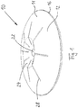
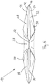
- the latent storage element 10 a housing 11, which consists of plastic, having a top 12 and a bottom 14, which are connected to each other at the periphery 16, for example, are welded.
- the latent storage element 10 has an approximately lenticular shape, with a thicker center region 18 and the thickness drops towards the edge region 20.
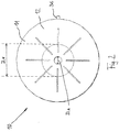
- a central recess 22 each with concave indentations 24, 26 on the top 12 and the bottom 14.
- radially extending beads 28 are provided on both the top 12 and on the bottom 14, which is completely from the edge portion 20 for Extend center region 18 out and have a consistently the same distance from the circumference horizon UH. These beads 28 are arranged on each side 12, 14 spaced apart by 45 °, wherein the opposite beads of top 12 and bottom 14 are each arranged offset from one another in the middle, resulting in a continuous flow area 30 for the latent storage element 10 arranged in the latent storage material 32nd results in the density increase provided for weighting material 34 is.
- filling neck 36 which, after successful filling of the latent storage element 10, has been sealingly welded to latent storage material 32 and weighting material 34 as the first leveling material.
- no bead 28 is provided in the upper side 12 so as not to obstruct the filling process.
- a small air bubble 38 is formed by the filling, which is used for volume compensation during the phase change and at the same time represents a second leveling material.
- the latent storage material 32 is, for example, a paraffin-based PCM with a phase change temperature of, for. B. 53 ° C the company Axiotherm (name: ATP 53).
- the weighting material 34 used is quartz sand (particle size distribution 0.063-2 mm).
- the diameter of the housing 11 is about 18 cm on the circumference 16 (with areas of about 5 cm to about 50 cm are also well used).
- the maximum height h of the housing 11 is about 3 cm (with areas of about 1 cm to about 8 cm are also good use).
- the diameter D_E of the indentations 24, 26 is about 6.3 cm (with areas of about 3 cm to about 20 cm are also good use) and the diameter D_A of the recess 22 is about 1.2 cm (with areas from about 0.5 cm to about 5 cm are also good).
- the Wall thickness of the housing is about 0.1 cm.
- the total volume of the housing 11 is thus about 382 ml, the air bubble 38 occupies a volume of about 5-8 ml and also serves to volume compensation.
- the volume fraction of the first leveling material 34 is adjusted relative to the volume fraction of the second leveling material 38 and the density of the latent storage material 32 in conjunction with the total volume of the encapsulation 11 so that the beneficial effects of leveling can be achieved.
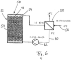
- the latent memory 50 according to the invention is shown in two different operating states, the container 51 is provided with a bed 52 of latent storage elements 10 according to the invention.
- the heat exchange medium 54 water, optionally added with additives such as antifreeze agents, inhibitors, corrosion protection, used, wherein the volume-loading ratio between water and latent storage elements 10 is about 1: 1.
- Fig. 6 are the conditions when loading the latent memory 50 with cold from a refrigeration circuit 56 via a heat exchanger 58, which performs a hydraulic media separation between the refrigerant circuit 56 (secondary circuit) and heat exchanger circuit 60 (primary circuit) of the latent memory 50 shown.
- a pump 62 is provided in the primary circuit 60.
- the latent memory 50 can also be operated directly, that is to say without system separation via a heat exchanger 58. In the case of a system separation, however, the required amounts of energy and temperatures can advantageously be optimally adjusted via different mass flows in the primary 60 and secondary circuit 56.
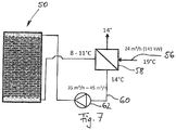
- Fig. 7 the corresponding conditions in the cold withdrawal from the latent memory 50 are shown.
- the latent memory 50 is a hybrid memory in which macro-encapsulated PCM 32 is located in a water-filled container 56.
- the macroencapsulations 11 are constructed in such a way that, in addition to a large surface area, the PCM layer thicknesses are kept so low that the entire PCM 32 participates in the phase change process and at the same time a stratification 52 of the layered latent storage elements 10 that can be flowed through over the whole area.
- the water 54 contained in the latent memory 50 is also used for the energy balance and dynamics of the latent memory 50. Due to the mass of the water 54 more or less significant amounts of energy are stored in the water content in all temperature ranges, depending on the temperature difference. Due to the system separation of the latent memory 50 through the plate heat exchanger 58 from the secondary circuit 56, this storage water 54 runs pump-supported in the primary circuit 60. This keeps the amount of energy stored in the storage system.
- the water 54 thus serves on the one hand as a carrier for the thermal energy for coupling and decoupling of the thermal energy and on the other hand as a sensitive storage medium.
- the latent memory 50 according to the invention can now, for example, be integrated in the energy process of a building (not shown) in which an absorption refrigeration machine (not shown), for example, operated with lithium bromide / water and used for air conditioning of the rooms, and in apparative supplement a corresponding dimensioned combined heat and power plant (CHP) - and heat pump technology, solar thermal (not shown) are provided:
- an absorption refrigeration machine for example, operated with lithium bromide / water and used for air conditioning of the rooms
- CHP combined heat and power plant
- solar thermal not shown
- an absorption refrigeration machine used for example, for cooling purposes runs at respectively favorable operating points or in the case of pure need
- part of the cooling energy is used directly for cooling the building.
- the other part of the Energy streams can be stored in the latent memory 50.
- This excess cold due to the small temperature differences, in which modern refrigeration systems are driven for economic and technical reasons and therefore could be stored in a sensitive storage, which would contain water, for example, only a relatively small proportion, can be optimally used.
- the cold-loaded latent memory 50 is then immediately available as an additional peak-load memory or redundancy (eg in the case of maintenance) to cover the necessary power peaks.
- the latent memory 50 according to the invention operates at constant temperatures near the phase change temperature of the PCM 32 and can store a lot of thermal energy through the phase change of the PCM at small temperature differences and release again.
- the latent memory 50 is designed, for example, as a peak-load memory with a PCM content of 2,280 kg PCM 32 and 6,500 kg water 54. This results in a temperature difference of 8K a capacity of 125.4 kWh for the PCM 32 and 60.3 kWh for the water content 54, so a total capacity of 185.7 kWh.
- the power is between 25-50 kW, depending on volume flow ratio, temperature difference and time duration. By varying the volume flows in the primary 60 and secondary 56, the power between the two circuits 56, 60 can be slidably adjusted.
- the latent accumulator 50 is capable, with suitable thermal conditioning, of releasing sensible cooling energy first, without delay, due to the water content, and then releasing the latently stored energy due to the latent storage material 32 without appreciable transition.
- a sudden increase in cooling demand eg arrival of a very large group of visitors in a public building
- one or more latent memories 50 can simply be discharged into a corresponding secondary circuit 56 (room cooling circuit).
- This is done in an energetically favorable, continuous process, since due to the continuous discharge temperature no energy-consuming measures such as constant pump volume flow changes must be made. This results in a smoothing of the power and temperature profile / absorption of excess cooling energy (if the cooling requirement decreases).
- the CHP and heat pump systems operating in parallel benefit from this process stabilization.
- This interdependent energy systems are basically dominated by the memory system used: without or with a pure sensitive memory (water), the sequentially switched system components are forced to a steady clocks or linear performance increase to operate the rising storage water temperatures.
- CHP and heat pump systems are basically dominated by the memory system used: without or with a pure sensitive memory (water), the sequentially switched system components are forced to a steady clocks or linear performance increase to operate the rising storage water temperatures.
- the service life of the system components is shortened.
- an energetically meaningful regulation is hardly possible.
- Just putting the heat pump in the high-pressure area is associated with extreme temperature differences in the clocking and is highly counterproductive both energetically and technically.
- the sliding operation of the energy producers involved is automatically controlled by buffering large amounts of energy at a constant temperature by means of this counter-buffering.
- the chiller can go through with a constant power without clocking or constantly having to adjust the performance to the current cooling load requirements.
- An absorption refrigeration system with the latent storage device 50 according to the invention has a powerful and high-capacity cold sink with a constant operating temperature. As a result, a clocking the otherwise continuously operating chiller is prevented, energetically unwanted removal and startup processes are thus avoided.
- phase change temperature of 53 ° C
- it can in principle be used for working temperature ranges or phase change temperatures at least between -30 to 200 ° C.
- phase change material Due to the constant storage temperature determined by the phase change material, this application, with its capacity and performance data, is excellently suited for highly efficient energy storage and thus operation in volatile or pulsating energy suppliers such as power plants.
- the present invention has provided a macroencapsulation 11 for latent-storage materials which forms a thermally-functional, cycle-stable and economical unit, so that it is very easy and inexpensive to build up latent reservoirs 50 which have an excellent heat absorption and delivery efficiency have.
Landscapes
- Engineering & Computer Science (AREA)
- Physics & Mathematics (AREA)
- Thermal Sciences (AREA)
- Mechanical Engineering (AREA)
- General Engineering & Computer Science (AREA)
- Central Heating Systems (AREA)
Priority Applications (1)
| Application Number | Priority Date | Filing Date | Title |
|---|---|---|---|
| PL17173081T PL3249335T3 (pl) | 2016-05-27 | 2017-05-26 | Element magazynowania utajonego, kapsułkowanie dla materiału magazynowania utajonego i magazyn utajony |
Applications Claiming Priority (2)
| Application Number | Priority Date | Filing Date | Title |
|---|---|---|---|
| DE102016109827.2A DE102016109827A1 (de) | 2016-05-27 | 2016-05-27 | Latentspeicherelement, Verkapselung für ein Latentspeichermaterial und Latentspeicher |
| DE102016109825.6A DE102016109825A1 (de) | 2016-05-27 | 2016-05-27 | Latentspeicherelement, Verkapselung für ein Latentspeichermaterial und Latentspeicher |
Publications (2)
| Publication Number | Publication Date |
|---|---|
| EP3249335A1 true EP3249335A1 (fr) | 2017-11-29 |
| EP3249335B1 EP3249335B1 (fr) | 2021-03-03 |
Family
ID=58873643
Family Applications (1)
| Application Number | Title | Priority Date | Filing Date |
|---|---|---|---|
| EP17173081.5A Active EP3249335B1 (fr) | 2016-05-27 | 2017-05-26 | Élément d'accumulateur de chaleur latente, encapsulation pour un matériau à chaleur latente et accumulateur de chaleur latente |
Country Status (4)
| Country | Link |
|---|---|
| EP (1) | EP3249335B1 (fr) |
| DK (1) | DK3249335T3 (fr) |
| ES (1) | ES2870918T3 (fr) |
| PL (1) | PL3249335T3 (fr) |
Cited By (3)
| Publication number | Priority date | Publication date | Assignee | Title |
|---|---|---|---|---|
| CN108955331A (zh) * | 2018-05-04 | 2018-12-07 | 谦茂节能科技(上海)有限公司 | 一种相变储能元件 |
| CN112611245A (zh) * | 2020-12-30 | 2021-04-06 | 思安新能源股份有限公司 | 一种柱式相变储热装置及其储热模块的制作方法 |
| EP4151695A1 (fr) | 2021-09-16 | 2023-03-22 | Cowa Thermal Solutions AG | Capsule d'accumulateur de chaleur dotée d'une matière à changement de phase |
Families Citing this family (1)
| Publication number | Priority date | Publication date | Assignee | Title |
|---|---|---|---|---|
| DE102022134378A1 (de) | 2022-12-21 | 2024-06-27 | kraftBoxx GmbH | Verfahren zur Gebäudeklimatisierung |
Citations (4)
| Publication number | Priority date | Publication date | Assignee | Title |
|---|---|---|---|---|
| JPH1089821A (ja) * | 1996-09-10 | 1998-04-10 | Sanyo Electric Co Ltd | 蓄熱・蓄冷流動体 |
| EP2492119A2 (fr) * | 2011-02-22 | 2012-08-29 | Handtmann Systemtechnik GmbH & Co. KG | Accumulateur thermique latent |
| WO2012138978A2 (fr) * | 2011-04-06 | 2012-10-11 | Dow Global Technologies Llc | Capsules en forme de dôme de matériau de stockage d'énergie thermique pour stockage de chaleur amélioré |
| EP2657629A1 (fr) * | 2010-12-24 | 2013-10-30 | Eikan Shoji Co., Ltd. | Module de régulation de température corporelle et support de module pour attacher celui-ci |
-
2017
- 2017-05-26 EP EP17173081.5A patent/EP3249335B1/fr active Active
- 2017-05-26 ES ES17173081T patent/ES2870918T3/es active Active
- 2017-05-26 PL PL17173081T patent/PL3249335T3/pl unknown
- 2017-05-26 DK DK17173081.5T patent/DK3249335T3/da active
Patent Citations (4)
| Publication number | Priority date | Publication date | Assignee | Title |
|---|---|---|---|---|
| JPH1089821A (ja) * | 1996-09-10 | 1998-04-10 | Sanyo Electric Co Ltd | 蓄熱・蓄冷流動体 |
| EP2657629A1 (fr) * | 2010-12-24 | 2013-10-30 | Eikan Shoji Co., Ltd. | Module de régulation de température corporelle et support de module pour attacher celui-ci |
| EP2492119A2 (fr) * | 2011-02-22 | 2012-08-29 | Handtmann Systemtechnik GmbH & Co. KG | Accumulateur thermique latent |
| WO2012138978A2 (fr) * | 2011-04-06 | 2012-10-11 | Dow Global Technologies Llc | Capsules en forme de dôme de matériau de stockage d'énergie thermique pour stockage de chaleur amélioré |
Cited By (3)
| Publication number | Priority date | Publication date | Assignee | Title |
|---|---|---|---|---|
| CN108955331A (zh) * | 2018-05-04 | 2018-12-07 | 谦茂节能科技(上海)有限公司 | 一种相变储能元件 |
| CN112611245A (zh) * | 2020-12-30 | 2021-04-06 | 思安新能源股份有限公司 | 一种柱式相变储热装置及其储热模块的制作方法 |
| EP4151695A1 (fr) | 2021-09-16 | 2023-03-22 | Cowa Thermal Solutions AG | Capsule d'accumulateur de chaleur dotée d'une matière à changement de phase |
Also Published As
| Publication number | Publication date |
|---|---|
| PL3249335T3 (pl) | 2021-11-08 |
| ES2870918T3 (es) | 2021-10-28 |
| EP3249335B1 (fr) | 2021-03-03 |
| DK3249335T3 (da) | 2021-05-25 |
Similar Documents
| Publication | Publication Date | Title |
|---|---|---|
| EP3249335B1 (fr) | Élément d'accumulateur de chaleur latente, encapsulation pour un matériau à chaleur latente et accumulateur de chaleur latente | |
| Mathur et al. | Using encapsulated phase change salts for concentrated solar power plant | |
| AT508992B1 (de) | Latentwärmespeicher | |
| CH703780A2 (de) | Wärmespeicher. | |
| EP1797382A1 (fr) | Dispositif de refroidissement de produits alimentaires | |
| EP2256451B1 (fr) | Dispositif de stockage de chaleur | |
| Elfeky et al. | Cycle cut-off criterion effect on the performance of cascaded, sensible, combined sensible-latent heat storage tank for concentrating solar power plants | |
| EP2543949A2 (fr) | Accumulateur thermique pourvu d'un récipient en partie rempli de liquide | |
| WO2012097861A1 (fr) | Accumulateur de chaleur latente | |
| EP1767882B1 (fr) | Absorbeur solaire | |
| Al-Shannaq et al. | Cooling of milk on dairy farms: an application of a novel ice encapsulated storage system in New Zealand | |
| DE102016109825A1 (de) | Latentspeicherelement, Verkapselung für ein Latentspeichermaterial und Latentspeicher | |
| WO2014089717A1 (fr) | Procédé et dispositif de génération d'un flux de fluide caloporteur | |
| DE102010028676A1 (de) | Verfahren zur Aufnahme, Abgabe und Speicherung von Wärme sowie Latentwärmespeicher zur Anwendung des Verfahrens | |
| DE102012000143A1 (de) | Verfahren und Vorrichtung zur Wärmeübertragung und Wärmespeicherung unter Nutzung des spezifischen und latenten Wärmeinhaltes von Stoffen | |
| AT516315B1 (de) | Wärmespeicher | |
| DE102016109827A1 (de) | Latentspeicherelement, Verkapselung für ein Latentspeichermaterial und Latentspeicher | |
| DE102015117848A1 (de) | Fluidsystem und Verfahren zum Steuern eines Fluidsystems | |
| DE10108150A1 (de) | Latentwärmespeicher | |
| WO2009036974A2 (fr) | Moyen d'accumulation de chaleur latente | |
| DE202007008684U1 (de) | Latentwärmezelle | |
| CH641542A5 (en) | Heat accumulator | |
| DE202019105225U1 (de) | Wärmeaustauscher | |
| DE102011100219B4 (de) | Speichereinrichtung | |
| DE3324943C2 (fr) |
Legal Events
| Date | Code | Title | Description |
|---|---|---|---|
| PUAI | Public reference made under article 153(3) epc to a published international application that has entered the european phase |
Free format text: ORIGINAL CODE: 0009012 |
|
| STAA | Information on the status of an ep patent application or granted ep patent |
Free format text: STATUS: THE APPLICATION HAS BEEN PUBLISHED |
|
| AK | Designated contracting states |
Kind code of ref document: A1 Designated state(s): AL AT BE BG CH CY CZ DE DK EE ES FI FR GB GR HR HU IE IS IT LI LT LU LV MC MK MT NL NO PL PT RO RS SE SI SK SM TR |
|
| AX | Request for extension of the european patent |
Extension state: BA ME |
|
| STAA | Information on the status of an ep patent application or granted ep patent |
Free format text: STATUS: REQUEST FOR EXAMINATION WAS MADE |
|
| 17P | Request for examination filed |
Effective date: 20180529 |
|
| RBV | Designated contracting states (corrected) |
Designated state(s): AL AT BE BG CH CY CZ DE DK EE ES FI FR GB GR HR HU IE IS IT LI LT LU LV MC MK MT NL NO PL PT RO RS SE SI SK SM TR |
|
| RIC1 | Information provided on ipc code assigned before grant |
Ipc: F28D 20/00 20060101ALN20200625BHEP Ipc: F28D 20/02 20060101AFI20200625BHEP |
|
| RIC1 | Information provided on ipc code assigned before grant |
Ipc: F28D 20/02 20060101AFI20200710BHEP Ipc: F28D 20/00 20060101ALN20200710BHEP |
|
| GRAP | Despatch of communication of intention to grant a patent |
Free format text: ORIGINAL CODE: EPIDOSNIGR1 |
|
| STAA | Information on the status of an ep patent application or granted ep patent |
Free format text: STATUS: GRANT OF PATENT IS INTENDED |
|
| INTG | Intention to grant announced |
Effective date: 20200923 |
|
| GRAS | Grant fee paid |
Free format text: ORIGINAL CODE: EPIDOSNIGR3 |
|
| GRAA | (expected) grant |
Free format text: ORIGINAL CODE: 0009210 |
|
| STAA | Information on the status of an ep patent application or granted ep patent |
Free format text: STATUS: THE PATENT HAS BEEN GRANTED |
|
| AK | Designated contracting states |
Kind code of ref document: B1 Designated state(s): AL AT BE BG CH CY CZ DE DK EE ES FI FR GB GR HR HU IE IS IT LI LT LU LV MC MK MT NL NO PL PT RO RS SE SI SK SM TR |
|
| REG | Reference to a national code |
Ref country code: GB Ref legal event code: FG4D Free format text: NOT ENGLISH |
|
| REG | Reference to a national code |
Ref country code: CH Ref legal event code: EP Ref country code: AT Ref legal event code: REF Ref document number: 1367663 Country of ref document: AT Kind code of ref document: T Effective date: 20210315 |
|
| REG | Reference to a national code |
Ref country code: DE Ref legal event code: R096 Ref document number: 502017009540 Country of ref document: DE |
|
| REG | Reference to a national code |
Ref country code: IE Ref legal event code: FG4D Free format text: LANGUAGE OF EP DOCUMENT: GERMAN |
|
| REG | Reference to a national code |
Ref country code: DK Ref legal event code: T3 Effective date: 20210521 |
|
| REG | Reference to a national code |
Ref country code: FI Ref legal event code: FGE |
|
| REG | Reference to a national code |
Ref country code: NL Ref legal event code: FP |
|
| REG | Reference to a national code |
Ref country code: LT Ref legal event code: MG9D |
|
| REG | Reference to a national code |
Ref country code: NO Ref legal event code: T2 Effective date: 20210303 |
|
| PG25 | Lapsed in a contracting state [announced via postgrant information from national office to epo] |
Ref country code: LT Free format text: LAPSE BECAUSE OF FAILURE TO SUBMIT A TRANSLATION OF THE DESCRIPTION OR TO PAY THE FEE WITHIN THE PRESCRIBED TIME-LIMIT Effective date: 20210303 Ref country code: BG Free format text: LAPSE BECAUSE OF FAILURE TO SUBMIT A TRANSLATION OF THE DESCRIPTION OR TO PAY THE FEE WITHIN THE PRESCRIBED TIME-LIMIT Effective date: 20210603 Ref country code: GR Free format text: LAPSE BECAUSE OF FAILURE TO SUBMIT A TRANSLATION OF THE DESCRIPTION OR TO PAY THE FEE WITHIN THE PRESCRIBED TIME-LIMIT Effective date: 20210604 Ref country code: HR Free format text: LAPSE BECAUSE OF FAILURE TO SUBMIT A TRANSLATION OF THE DESCRIPTION OR TO PAY THE FEE WITHIN THE PRESCRIBED TIME-LIMIT Effective date: 20210303 |
|
| PG25 | Lapsed in a contracting state [announced via postgrant information from national office to epo] |
Ref country code: SE Free format text: LAPSE BECAUSE OF FAILURE TO SUBMIT A TRANSLATION OF THE DESCRIPTION OR TO PAY THE FEE WITHIN THE PRESCRIBED TIME-LIMIT Effective date: 20210303 Ref country code: LV Free format text: LAPSE BECAUSE OF FAILURE TO SUBMIT A TRANSLATION OF THE DESCRIPTION OR TO PAY THE FEE WITHIN THE PRESCRIBED TIME-LIMIT Effective date: 20210303 Ref country code: RS Free format text: LAPSE BECAUSE OF FAILURE TO SUBMIT A TRANSLATION OF THE DESCRIPTION OR TO PAY THE FEE WITHIN THE PRESCRIBED TIME-LIMIT Effective date: 20210303 |
|
| REG | Reference to a national code |
Ref country code: ES Ref legal event code: FG2A Ref document number: 2870918 Country of ref document: ES Kind code of ref document: T3 Effective date: 20211028 |
|
| PG25 | Lapsed in a contracting state [announced via postgrant information from national office to epo] |
Ref country code: CZ Free format text: LAPSE BECAUSE OF FAILURE TO SUBMIT A TRANSLATION OF THE DESCRIPTION OR TO PAY THE FEE WITHIN THE PRESCRIBED TIME-LIMIT Effective date: 20210303 Ref country code: EE Free format text: LAPSE BECAUSE OF FAILURE TO SUBMIT A TRANSLATION OF THE DESCRIPTION OR TO PAY THE FEE WITHIN THE PRESCRIBED TIME-LIMIT Effective date: 20210303 Ref country code: SM Free format text: LAPSE BECAUSE OF FAILURE TO SUBMIT A TRANSLATION OF THE DESCRIPTION OR TO PAY THE FEE WITHIN THE PRESCRIBED TIME-LIMIT Effective date: 20210303 |
|
| PG25 | Lapsed in a contracting state [announced via postgrant information from national office to epo] |
Ref country code: IS Free format text: LAPSE BECAUSE OF FAILURE TO SUBMIT A TRANSLATION OF THE DESCRIPTION OR TO PAY THE FEE WITHIN THE PRESCRIBED TIME-LIMIT Effective date: 20210703 Ref country code: PT Free format text: LAPSE BECAUSE OF FAILURE TO SUBMIT A TRANSLATION OF THE DESCRIPTION OR TO PAY THE FEE WITHIN THE PRESCRIBED TIME-LIMIT Effective date: 20210705 Ref country code: RO Free format text: LAPSE BECAUSE OF FAILURE TO SUBMIT A TRANSLATION OF THE DESCRIPTION OR TO PAY THE FEE WITHIN THE PRESCRIBED TIME-LIMIT Effective date: 20210303 Ref country code: SK Free format text: LAPSE BECAUSE OF FAILURE TO SUBMIT A TRANSLATION OF THE DESCRIPTION OR TO PAY THE FEE WITHIN THE PRESCRIBED TIME-LIMIT Effective date: 20210303 |
|
| REG | Reference to a national code |
Ref country code: DE Ref legal event code: R097 Ref document number: 502017009540 Country of ref document: DE |
|
| PLBE | No opposition filed within time limit |
Free format text: ORIGINAL CODE: 0009261 |
|
| STAA | Information on the status of an ep patent application or granted ep patent |
Free format text: STATUS: NO OPPOSITION FILED WITHIN TIME LIMIT |
|
| PG25 | Lapsed in a contracting state [announced via postgrant information from national office to epo] |
Ref country code: AL Free format text: LAPSE BECAUSE OF FAILURE TO SUBMIT A TRANSLATION OF THE DESCRIPTION OR TO PAY THE FEE WITHIN THE PRESCRIBED TIME-LIMIT Effective date: 20210303 Ref country code: MC Free format text: LAPSE BECAUSE OF FAILURE TO SUBMIT A TRANSLATION OF THE DESCRIPTION OR TO PAY THE FEE WITHIN THE PRESCRIBED TIME-LIMIT Effective date: 20210303 Ref country code: LU Free format text: LAPSE BECAUSE OF NON-PAYMENT OF DUE FEES Effective date: 20210526 |
|
| 26N | No opposition filed |
Effective date: 20211206 |
|
| REG | Reference to a national code |
Ref country code: BE Ref legal event code: MM Effective date: 20210531 |
|
| PG25 | Lapsed in a contracting state [announced via postgrant information from national office to epo] |
Ref country code: SI Free format text: LAPSE BECAUSE OF FAILURE TO SUBMIT A TRANSLATION OF THE DESCRIPTION OR TO PAY THE FEE WITHIN THE PRESCRIBED TIME-LIMIT Effective date: 20210303 |
|
| PG25 | Lapsed in a contracting state [announced via postgrant information from national office to epo] |
Ref country code: IE Free format text: LAPSE BECAUSE OF NON-PAYMENT OF DUE FEES Effective date: 20210526 |
|
| PG25 | Lapsed in a contracting state [announced via postgrant information from national office to epo] |
Ref country code: IS Free format text: LAPSE BECAUSE OF FAILURE TO SUBMIT A TRANSLATION OF THE DESCRIPTION OR TO PAY THE FEE WITHIN THE PRESCRIBED TIME-LIMIT Effective date: 20210703 |
|
| PG25 | Lapsed in a contracting state [announced via postgrant information from national office to epo] |
Ref country code: BE Free format text: LAPSE BECAUSE OF NON-PAYMENT OF DUE FEES Effective date: 20210531 |
|
| PG25 | Lapsed in a contracting state [announced via postgrant information from national office to epo] |
Ref country code: HU Free format text: LAPSE BECAUSE OF FAILURE TO SUBMIT A TRANSLATION OF THE DESCRIPTION OR TO PAY THE FEE WITHIN THE PRESCRIBED TIME-LIMIT; INVALID AB INITIO Effective date: 20170526 |
|
| P01 | Opt-out of the competence of the unified patent court (upc) registered |
Effective date: 20230517 |
|
| PG25 | Lapsed in a contracting state [announced via postgrant information from national office to epo] |
Ref country code: CY Free format text: LAPSE BECAUSE OF FAILURE TO SUBMIT A TRANSLATION OF THE DESCRIPTION OR TO PAY THE FEE WITHIN THE PRESCRIBED TIME-LIMIT Effective date: 20210303 |
|
| P02 | Opt-out of the competence of the unified patent court (upc) changed |
Effective date: 20230530 |
|
| PGFP | Annual fee paid to national office [announced via postgrant information from national office to epo] |
Ref country code: FI Payment date: 20230523 Year of fee payment: 7 |
|
| PG25 | Lapsed in a contracting state [announced via postgrant information from national office to epo] |
Ref country code: MK Free format text: LAPSE BECAUSE OF FAILURE TO SUBMIT A TRANSLATION OF THE DESCRIPTION OR TO PAY THE FEE WITHIN THE PRESCRIBED TIME-LIMIT Effective date: 20210303 |
|
| PG25 | Lapsed in a contracting state [announced via postgrant information from national office to epo] |
Ref country code: MT Free format text: LAPSE BECAUSE OF FAILURE TO SUBMIT A TRANSLATION OF THE DESCRIPTION OR TO PAY THE FEE WITHIN THE PRESCRIBED TIME-LIMIT Effective date: 20210303 |
|
| PG25 | Lapsed in a contracting state [announced via postgrant information from national office to epo] |
Ref country code: FI Free format text: LAPSE BECAUSE OF NON-PAYMENT OF DUE FEES Effective date: 20240526 |
|
| PG25 | Lapsed in a contracting state [announced via postgrant information from national office to epo] |
Ref country code: FI Free format text: LAPSE BECAUSE OF NON-PAYMENT OF DUE FEES Effective date: 20240526 |
|
| PGFP | Annual fee paid to national office [announced via postgrant information from national office to epo] |
Ref country code: NL Payment date: 20250522 Year of fee payment: 9 |
|
| PGFP | Annual fee paid to national office [announced via postgrant information from national office to epo] |
Ref country code: PL Payment date: 20250515 Year of fee payment: 9 Ref country code: DE Payment date: 20250317 Year of fee payment: 9 |
|
| PGFP | Annual fee paid to national office [announced via postgrant information from national office to epo] |
Ref country code: ES Payment date: 20250616 Year of fee payment: 9 Ref country code: GB Payment date: 20250522 Year of fee payment: 9 Ref country code: DK Payment date: 20250521 Year of fee payment: 9 |
|
| PGFP | Annual fee paid to national office [announced via postgrant information from national office to epo] |
Ref country code: NO Payment date: 20250520 Year of fee payment: 9 |
|
| PGFP | Annual fee paid to national office [announced via postgrant information from national office to epo] |
Ref country code: IT Payment date: 20250530 Year of fee payment: 9 |
|
| PGFP | Annual fee paid to national office [announced via postgrant information from national office to epo] |
Ref country code: FR Payment date: 20250521 Year of fee payment: 9 |
|
| PGFP | Annual fee paid to national office [announced via postgrant information from national office to epo] |
Ref country code: CH Payment date: 20250601 Year of fee payment: 9 |
|
| PGFP | Annual fee paid to national office [announced via postgrant information from national office to epo] |
Ref country code: AT Payment date: 20250519 Year of fee payment: 9 |
|
| PG25 | Lapsed in a contracting state [announced via postgrant information from national office to epo] |
Ref country code: TR Free format text: LAPSE BECAUSE OF FAILURE TO SUBMIT A TRANSLATION OF THE DESCRIPTION OR TO PAY THE FEE WITHIN THE PRESCRIBED TIME-LIMIT Effective date: 20210303 |