EP3249366A1 - Verteilter glasfasersensor - Google Patents
Verteilter glasfasersensor Download PDFInfo
- Publication number
- EP3249366A1 EP3249366A1 EP17179882.0A EP17179882A EP3249366A1 EP 3249366 A1 EP3249366 A1 EP 3249366A1 EP 17179882 A EP17179882 A EP 17179882A EP 3249366 A1 EP3249366 A1 EP 3249366A1
- Authority
- EP
- European Patent Office
- Prior art keywords
- probe light
- sensor
- sensing
- backscattered
- wavelengths
- Prior art date
- Legal status (The legal status is an assumption and is not a legal conclusion. Google has not performed a legal analysis and makes no representation as to the accuracy of the status listed.)
- Granted
Links
Images

Classifications
-
- G—PHYSICS
- G01—MEASURING; TESTING
- G01N—INVESTIGATING OR ANALYSING MATERIALS BY DETERMINING THEIR CHEMICAL OR PHYSICAL PROPERTIES
- G01N21/00—Investigating or analysing materials by the use of optical means, i.e. using sub-millimetre waves, infrared, visible or ultraviolet light
- G01N21/17—Systems in which incident light is modified in accordance with the properties of the material investigated
- G01N21/47—Scattering, i.e. diffuse reflection
- G01N21/4738—Diffuse reflection, e.g. also for testing fluids, fibrous materials
- G01N21/474—Details of optical heads therefor, e.g. using optical fibres
-
- E—FIXED CONSTRUCTIONS
- E21—EARTH OR ROCK DRILLING; MINING
- E21B—EARTH OR ROCK DRILLING; OBTAINING OIL, GAS, WATER, SOLUBLE OR MELTABLE MATERIALS OR A SLURRY OF MINERALS FROM WELLS
- E21B47/00—Survey of boreholes or wells
- E21B47/06—Measuring temperature or pressure
-
- E—FIXED CONSTRUCTIONS
- E21—EARTH OR ROCK DRILLING; MINING
- E21B—EARTH OR ROCK DRILLING; OBTAINING OIL, GAS, WATER, SOLUBLE OR MELTABLE MATERIALS OR A SLURRY OF MINERALS FROM WELLS
- E21B47/00—Survey of boreholes or wells
- E21B47/12—Means for transmitting measuring-signals or control signals from the well to the surface, or from the surface to the well, e.g. for logging while drilling
- E21B47/13—Means for transmitting measuring-signals or control signals from the well to the surface, or from the surface to the well, e.g. for logging while drilling by electromagnetic energy, e.g. radio frequency
- E21B47/135—Means for transmitting measuring-signals or control signals from the well to the surface, or from the surface to the well, e.g. for logging while drilling by electromagnetic energy, e.g. radio frequency using light waves, e.g. infrared or ultraviolet waves
-
- G—PHYSICS
- G01—MEASURING; TESTING
- G01D—MEASURING NOT SPECIALLY ADAPTED FOR A SPECIFIC VARIABLE; ARRANGEMENTS FOR MEASURING TWO OR MORE VARIABLES NOT COVERED IN A SINGLE OTHER SUBCLASS; TARIFF METERING APPARATUS; MEASURING OR TESTING NOT OTHERWISE PROVIDED FOR
- G01D5/00—Mechanical means for transferring the output of a sensing member; Means for converting the output of a sensing member to another variable where the form or nature of the sensing member does not constrain the means for converting; Transducers not specially adapted for a specific variable
- G01D5/26—Mechanical means for transferring the output of a sensing member; Means for converting the output of a sensing member to another variable where the form or nature of the sensing member does not constrain the means for converting; Transducers not specially adapted for a specific variable characterised by optical transfer means, i.e. using infrared, visible, or ultraviolet light
- G01D5/32—Mechanical means for transferring the output of a sensing member; Means for converting the output of a sensing member to another variable where the form or nature of the sensing member does not constrain the means for converting; Transducers not specially adapted for a specific variable characterised by optical transfer means, i.e. using infrared, visible, or ultraviolet light with attenuation or whole or partial obturation of beams of light
- G01D5/34—Mechanical means for transferring the output of a sensing member; Means for converting the output of a sensing member to another variable where the form or nature of the sensing member does not constrain the means for converting; Transducers not specially adapted for a specific variable characterised by optical transfer means, i.e. using infrared, visible, or ultraviolet light with attenuation or whole or partial obturation of beams of light the beams of light being detected by photocells
- G01D5/353—Mechanical means for transferring the output of a sensing member; Means for converting the output of a sensing member to another variable where the form or nature of the sensing member does not constrain the means for converting; Transducers not specially adapted for a specific variable characterised by optical transfer means, i.e. using infrared, visible, or ultraviolet light with attenuation or whole or partial obturation of beams of light the beams of light being detected by photocells influencing the transmission properties of an optical fibre
- G01D5/35338—Mechanical means for transferring the output of a sensing member; Means for converting the output of a sensing member to another variable where the form or nature of the sensing member does not constrain the means for converting; Transducers not specially adapted for a specific variable characterised by optical transfer means, i.e. using infrared, visible, or ultraviolet light with attenuation or whole or partial obturation of beams of light the beams of light being detected by photocells influencing the transmission properties of an optical fibre using other arrangements than interferometer arrangements
- G01D5/35354—Sensor working in reflection
- G01D5/35358—Sensor working in reflection using backscattering to detect the measured quantity
- G01D5/35361—Sensor working in reflection using backscattering to detect the measured quantity using elastic backscattering to detect the measured quantity, e.g. using Rayleigh backscattering
-
- G—PHYSICS
- G01—MEASURING; TESTING
- G01D—MEASURING NOT SPECIALLY ADAPTED FOR A SPECIFIC VARIABLE; ARRANGEMENTS FOR MEASURING TWO OR MORE VARIABLES NOT COVERED IN A SINGLE OTHER SUBCLASS; TARIFF METERING APPARATUS; MEASURING OR TESTING NOT OTHERWISE PROVIDED FOR
- G01D5/00—Mechanical means for transferring the output of a sensing member; Means for converting the output of a sensing member to another variable where the form or nature of the sensing member does not constrain the means for converting; Transducers not specially adapted for a specific variable
- G01D5/26—Mechanical means for transferring the output of a sensing member; Means for converting the output of a sensing member to another variable where the form or nature of the sensing member does not constrain the means for converting; Transducers not specially adapted for a specific variable characterised by optical transfer means, i.e. using infrared, visible, or ultraviolet light
- G01D5/32—Mechanical means for transferring the output of a sensing member; Means for converting the output of a sensing member to another variable where the form or nature of the sensing member does not constrain the means for converting; Transducers not specially adapted for a specific variable characterised by optical transfer means, i.e. using infrared, visible, or ultraviolet light with attenuation or whole or partial obturation of beams of light
- G01D5/34—Mechanical means for transferring the output of a sensing member; Means for converting the output of a sensing member to another variable where the form or nature of the sensing member does not constrain the means for converting; Transducers not specially adapted for a specific variable characterised by optical transfer means, i.e. using infrared, visible, or ultraviolet light with attenuation or whole or partial obturation of beams of light the beams of light being detected by photocells
- G01D5/353—Mechanical means for transferring the output of a sensing member; Means for converting the output of a sensing member to another variable where the form or nature of the sensing member does not constrain the means for converting; Transducers not specially adapted for a specific variable characterised by optical transfer means, i.e. using infrared, visible, or ultraviolet light with attenuation or whole or partial obturation of beams of light the beams of light being detected by photocells influencing the transmission properties of an optical fibre
- G01D5/35383—Mechanical means for transferring the output of a sensing member; Means for converting the output of a sensing member to another variable where the form or nature of the sensing member does not constrain the means for converting; Transducers not specially adapted for a specific variable characterised by optical transfer means, i.e. using infrared, visible, or ultraviolet light with attenuation or whole or partial obturation of beams of light the beams of light being detected by photocells influencing the transmission properties of an optical fibre using multiple sensor devices using multiplexing techniques
- G01D5/35387—Mechanical means for transferring the output of a sensing member; Means for converting the output of a sensing member to another variable where the form or nature of the sensing member does not constrain the means for converting; Transducers not specially adapted for a specific variable characterised by optical transfer means, i.e. using infrared, visible, or ultraviolet light with attenuation or whole or partial obturation of beams of light the beams of light being detected by photocells influencing the transmission properties of an optical fibre using multiple sensor devices using multiplexing techniques using wavelength division multiplexing
-
- G—PHYSICS
- G01—MEASURING; TESTING
- G01N—INVESTIGATING OR ANALYSING MATERIALS BY DETERMINING THEIR CHEMICAL OR PHYSICAL PROPERTIES
- G01N2201/00—Features of devices classified in G01N21/00
- G01N2201/06—Illumination; Optics
- G01N2201/061—Sources
- G01N2201/06113—Coherent sources; lasers
-
- G—PHYSICS
- G01—MEASURING; TESTING
- G01N—INVESTIGATING OR ANALYSING MATERIALS BY DETERMINING THEIR CHEMICAL OR PHYSICAL PROPERTIES
- G01N2201/00—Features of devices classified in G01N21/00
- G01N2201/08—Optical fibres; light guides
- G01N2201/088—Using a sensor fibre
Definitions
- the present invention relates to distributed optical fibre sensors, in which one or more physical parameters are sensed as a function of position along a sensing optical fibre from the properties of probe light backscattered within the sensing fibre.
- the invention relates to optical time domain reflectometry (OTDR) sensors for use in sensing vibration, and such sensors which use phase sensitive OTDR techniques such as through the detection of coherent Rayleigh noise, or other interferometric techniques.
- OTDR optical time domain reflectometry
- Distributed optical fibre sensing is a well known approach to providing information about environmental conditions surrounding a sensing optical fibre. Fully-distributed sensing in principle provides spatially resolved information from every point along the fibre. Variables that can be sensed include temperature, static strain, pressure, and vibration.
- One such technique detects variations in refractive index, induced by a physical forcing such as vibration, in the coherent Rayleigh noise profile of light backscattered within a sensing optical fibre interrogated by an optical source of limited bandwidth.
- Such Rayleigh noise profiles arise from interference between the many components of the backscattered light originating from different points along a portion of the sensing optical fibre illuminated by the optical source.
- Such techniques are described, for example, in WO2008/056143 .
- Another such technique detects variations in fibre temperature and strain through their effects on Brillouin scattering of probe light launched into the fibre.
- Such techniques are described, for example, in Horiguchi et al., Journal of Lightwave Technology, vol. 13, no. 7, July 1995 .
- the invention provides a distributed optical fibre sensor for determining one or more parameters as functions of position along a plurality of sensing optical fibres from properties of probe light backscattered within the sensing optical fibres, for example to monitor the environment along each sensing optical fibre, the sensor comprising:
- Such a sensor can make use of optical pathways and components common to all of the wavelengths to reduce the size, complexity and cost of implementing interrogation of multiple sensing fibres.
- the invention can also be applied to a single loop of sensing fibre, with two interrogated pathways being opposite directions around the same loop. Accordingly, the invention also provides a distributed optical fibre sensor for determining one or more parameters as functions of position in both directions along a loop of sensing optical fibre from properties of probe light backscattered within the sensing optical fibre, the sensor comprising: a probe light source arranged to generate probe light pulses each at one of two optical wavelengths; a coupler arranged to receive the probe light pulses from the probe light source and to direct pulses of each wavelength into the sensing optical fibre in a different corresponding direction, and to collect probe light backscattered within the sensing optical fibre; a detector arranged to receive the collected backscattered light and to separately detect light of each of said different wavelengths in said collected backscattered light; and an analyser arranged to determine said one or more parameters as functions of position in each direction along the sensing optical fibre from said detected backscattered light of each corresponding wavelength.
- the coupler may be a wavelength multiplexer/demultiplexer component arranged to receive the probe light pulses of all of the plurality of optical wavelengths, and to demultiplex each wavelength onto a different sensing fibre or different direction around the fibre loop.
- a single connector waveguide maybe used to deliver the pulses of all of the wavelengths to the coupler and to carry the collected backscattered light of all of the wavelengths from the coupler for delivery to the detector.
- the probe light pulses may be conditioned using one or more source optical conditioning components through which the probe light pulses of all of the plurality of wavelengths are passed before being launched into the sensing optical fibre or fibres.
- the backscattered light may be conditioned using one or more detector optical conditioning components through which all of the collected backscattered light is passed before being detected.
- optical conditioning components may include optical amplifiers, bandpass filters and similar.
- the probe light pulses of the plurality of wavelengths may be generated using a switched wavelength laser, or using separate correspondingly tuned laser sources, or by applying wavelength shifting techniques to the light from a single, master laser source.
- the probe light source may be arranged to generate the probe light pulses such that backscattered light of at least two of the plurality of wavelengths is detected by the detector at the same time. Note that a single probe light pulse of a few nanoseconds duration launched into a sensing optical fibre will typically give rise to backscattered light spread over a few microseconds, depending on the length of the sensing optical fibre.
- the probe light source may therefore be arranged to generate the probe light pulses such that backscattered light of more than one, and optionally all of the plurality of wavelengths at least partially overlaps at the detector.
- the parameter may be a parameter of the environment around the sensing fibre.
- the sensor may be used to detect a variety of parameters, for example vibration, temperature, pressure, and strain at the sensor fibre or fibres.
- the analyser may be arranged to determine the same parameter in respect of each of said sensing fibres or loop direction, or to determine different parameters on some or all of the fibres or loop directions. Such parameters may be detected using a variety of optical techniques which are known in the art.
- the invention may, for example be implemented such that the detector detects coherent Rayleigh noise, Rayleigh backscatter, Raman scattering or Brillouin scattering at one or more of said plurality of wavelengths, and the analyser determines one or more of said parameters from properties of the coherent Rayleigh noise, Rayleigh backscatter, Raman scattering or Brillouin scattering.
- the invention may be used to monitor a variety of environments and structures, such as oil, gas and other geological wells, along a plurality of branches of such wells, pipelines, building structures, and along security perimeters.
- the invention also provides methods corresponding to the apparatus discussed above, for example a method of operating a distributed optical fibre sensor to determine one or more parameters as functions of position along a plurality of sensing optical fibres from properties of probe light backscattered within the sensing optical fibres, to thereby monitor the environments of said sensing optical fibres, comprising: operating a probe light source to generate probe light pulses each at one of a plurality of optical wavelengths; coupling the probe light pulses of each wavelength into a different corresponding one of said sensing optical fibres; collecting probe light backscattered within the sensing optical fibres; separately and simultaneously detecting light of each of said different wavelengths in said collected backscattered light; and determining said one or more parameters as functions of positions along each of the sensing optical fibres from said detected backscattered light of each corresponding wavelength.
- the invention may similarly be applied as a method to a loop of sensing fibre with different probe light pulse wavelengths being used in each direction around the loop.
- the probe light pulses may be delivered to the sensing optical fibre or fibres and the backscattered probe light may be collected and combined from the sensing optical fibre or fibres by a wavelength multiplexer/demultiplexer component.
- the timing of the generation of probe light pulses by the probe light source may be controlled such that at least some of the collected backscattered light contains light of more than one of said wavelengths.
- the steps of operating the probe light source and detecting the backscattered light may be implemented such that coherent Rayleigh noise is detected in the backscattered light, and the step of determining comprises determination of said one or more parameters from properties of the coherent Rayleigh noise.
- the one or more determined parameters may include a parameter representative of vibration in the one or more corresponding sensing optical fibres.
- the invention may also provide a method of determining parameters along a plurality of extended paths, comprising disposing a sensing optical fibre along each of said paths, coupling the sensing optical fibres to a single interrogator unit, using the interrogator unit to launch probe light pulses of a different wavelength along each of said sensing optical fibres, and using the interrogator unit to detect and analyse the probe light backscattered within the sensing optical fibres to determine said parameters.
- This method may also be applied to interrogating in opposite directions along a loop of sensing optical fibre.
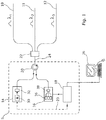
- An interrogator unit 5 of the sensor includes a probe light source 14 for generating probe light pulses of suitable timings, shapes and wavelengths, a detector 16 for detecting probe light resulting from the probe light pulses being backscattered within the sensing fibres 10, 11, 12, and an analyser 18 for processing data, such as properties of the backscattered and detected light, which has been received from the detector.
- the probe light source forms probe light pulses, each pulse having an optical wavelength selected from a plurality of different wavelengths. Three such wavelengths are used in the figure, shown as ⁇ 1 , ⁇ 2 and ⁇ 3 .
- the probe light pulses are forwarded to an optical circulator 20 and from there on to an optical coupler 22.
- the coupler provides a wavelength multiplex/demultiplex function, delivering probe light pulses of each of the wavelengths to a corresponding one of the sensing fibres 10, 11, 12 as shown in the figure.
- the circulator 20 is shown as forming part of the interrogator unit 5, and the coupler as being external to the interrogator unit. However, other arrangements may be used as appropriate to the implementation, for example by including the coupler within the interrogator unit 5.
- Probe light backscattered within the sensing fibres 10, 11, 12, is combined together at the coupler 22, and delivered from there to the circulator 20 which passes the collected light on to the detector 16.
- the probe light pulses and collected backscattered light may be coupled between the circulator 20 and coupler 22 using a single connector waveguide 24, typically a single optical fibre, and each of the probe light source and the detector may similarly be linked to the circulator using single optical fibres.
- the analyser 18 outputs analysis results such as a determination of the one or more physical parameters, and in figure 1 this output is passed to a computer display 26, although various other types of output mechanism may be used.
- the analyser 18 may also use data derived from the detected backscatter to provide control signals 23 to the probe light source 14.
- control signals may be provided, including signals controlling the durations, timings and wavelengths of probe light pulses, as required.
- the control functions may be implemented separately to the analyser 18, for example in a separate controller element (not shown in the figure).
- the probe light source is arranged to generate the probe light pulses of different wavelengths according to particular timing schemes. Because a different wavelength is used to interrogate each sensing optical fibre, it is not necessary to wait until all the backscattered light of one pulse has arrived at the detector before launching another probe light pulse. Pulses of different wavelengths may be generated at the same time so as to overlap, or so that backscattered light from one or more pulses of different wavelengths, or pulses of all of the wavelengths, overlap at the detector. In particular, the detector may be arranged to separately detect backscattered light of each of the wavelengths, and more particularly to separately and simultaneously detect backscattered light of more than one or of all of the wavelengths.
- the probe light source contains one or more laser sources 30 to generate the probe light pulses.
- the pulses of all of the different wavelengths may be generated using a single switched wavelength laser source, suitably controlled, or pulses of the different wavelengths may be generated using discrete separate laser sources, or using a single laser with a wavelength shifting method.
- the probe light pulses are conditioned in the probe light source by one or more source optical conditioning components 32. If multiple laser sources are used then some of these components may be specific to one or more of the lasers, but typically one or more of the source optical conditioning components will be used to condition pulses of all of the wavelengths.
- the detector 16 preferably uses a different detector element 36 to detect backscattered light of each of the different probe light wavelengths.
- the detector elements may be, for example, suitable photodiodes, with wavelength selective components used to direct the collected light to the appropriate detector.
- the backscattered light is conditioned in the detector using one or more detector optical conditioning components, and typically at least one of the detector optical conditioning components is used to condition backscattered light of all of the generated wavelengths. Use of a common optical pathway and components common to all of the wavelengths simplifies the interrogator and reduces costs.
- the optical conditioning components in the interrogator including individual components which are used to condition light of all of the wavelengths, may include optical amplifiers, band pass filters, and other components.
- the sensing fibres may all be of the same type, or may be of different types including, without limitation, single mode fibre, multimode fibre, fibre with high birefringence, and fibre especially adapted or encased so as to respond or enhance the response to changes in one or more of pressure, temperature, and other parameters which are to be measured.
- the sensing fibres may be interrogated using techniques based on Rayleigh backscatter, coherent Rayleigh noise, Raman scattering, and Brillouin scattering.
- all of the sensing fibres are interrogated using the same technique, or the same combination of techniques, and in other embodiments different techniques or combinations of techniques are used on some or all of the sensing fibres.
- the sensor may use selected ones of these techniques as appropriate to measure parameters such as vibration, static or transient strain, temperature, and pressure.
- FIG 1 The arrangement of figure 1 can be used in a variety of situations.
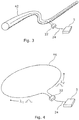
- Figure 2a illustrates the sensor being used to monitor multiple branches of a single geological borehole 40, such as an oil or gas well. Each branch 42 is monitored using a different one of the sensing fibres.
- multiple sensing fibres are used to monitor the same borehole 40, for example to provide redundancy, or to use different sensing fibres to sense different parameters.
- multiple sensing fibres are used to monitor separate boreholes 40.
- the multiple sensing fibres are used to monitor along different pathways across or through a building structure or infrastructure component, such as a bridge, a pipe line or a roadway.
- Figure 3a illustrates use of the invention to increase the length of a pipeline 42 which can be monitored using a single interrogator unit 5, by directing sensing optical fibres in opposite directions along the pipeline from the interrogator unit.
- a similar arrangement can be used for other extended structures, or for security / intrusion monitoring across long stretches of land or fences and other types of borders.
- an open loop 46 of sensing optical fibre is disposed through an environment to be sensed, for example along a borehole, fence, along the ground etc.
- Probe light pulses of one optical wavelength are launched into the loop 46 in one direction, and pulses of a second wavelength are launched into the loop 48 in the opposite direction.
- the loop appears to be two separate fibres extending individually through the environment.
- the loop topology allows interrogation along the full length of the sensing fibre to continue even when the loop is broken in one place.
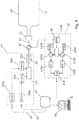
- Figure 5 shows details of optics and electronics which may be used for putting into effect the distributed optical fibre sensor described above.
- Two separate optical sources 50a and 50b are shown within the probe light source 14, each optical source emitting a narrow band of wavelengths centred at ⁇ a and ⁇ b respectively. It would alternatively be possible to use a single, wavelength switched source, or a combination of sources with switchable and fixed wavelengths. Since two separate optical sources are shown in this embodiment, a wavelength combiner component 114 is required to route the two signal wavelengths onto a common optical path. If a wavelength switched source were to be used alone, then this component would not be required.
- the wavelengths ⁇ a and ⁇ b used in the system could lie within the operating band of typical erbium-doped fibre amplifiers, between 1528 nm to 1562 nm, and the optical sources could be distributed-feedback laser diodes.
- the two signal wavelengths are then fed through an optical conditioning chain 116 whose function is to amplify the light to suitable power levels and to provide optical filtering to avoid the deleterious effects of amplified spontaneous emission (ASE) from the amplifier elements.
- This optical conditioning chain comprises optical components 32 through which probe light pulses of both pulse wavelengths pass. Typically, peak powers of the order of 1W might be delivered to the sensing fibres 10, 11 and the ASE suppression bandwidth might be ⁇ 0.2 nm.
- Light emerging from the optical conditioning chain 116 is directed to the optical circulator 20 that serves to route probe light from the probe light source 14 to the coupler 22 which is provided by a wavelength multiplexer/demultiplexer component.
- the coupler 22 couples the probe light pulses of each wavelength into a different one of the sensing fibres 10, 11 and light from the sensing fibres back to the circulator 20 which couples the light from the sensing fibres to the detector 16.
- Backscattered light returning from the sensing fibres through the coupler and circulator is directed into the detector 16, and in particular into an optical signal conditioning chain 120.
- This chain contains further amplification and filtering components 38 required to increase the received signal powers to levels suitable for low-noise detection.
- the two signal wavelengths ⁇ a and ⁇ b are separated by the wavelength de-multiplexing component 122.
- the two signal wavelengths ⁇ a and ⁇ b are each further filtered to a narrow band using components 124a, 124b and 126 a, 126b respectively.
- the narrow band filters are fibre Bragg gratings with approximately 80 pm reflection bandwidth.
- each wavelength is received by its own photodetector, 130a and 130b respectively. Conveniently, PIN photodiodes may be used for this purpose.
- each photodetector 130a, 130b are digitized by the data acquisition unit 134 and fed to the analyser 18, which controls the optical sources 110a and 110b via driver circuits 150a and 150b.
- these driver circuits may also serve to fine-tune the wavelength of the optical sources. This can be achieved, for example, by control of laser temperature.
- fine-tuning of the centre wavelength of different probe light pulses might be accomplished by controlled filtering either before the unconditioned probe light enters the wavelength combiner 114 or after leaving the wavelength demultiplexer 122. In the latter case, the centre wavelength of one or both of the fibre Bragg gratings could be thermally tuned.
- fine control of wavelength might alternatively be achieved by phase or frequency modulation of light using a radio frequency optical modulator together with appropriate filtering.
- the analyser 18 Based on analysis of the backscattered probe light, the analyser 18 provides control signals to the driver circuits 150a, 150b, for example to control probe light pulse length and probe pulse wavelength as required.
Landscapes
- Physics & Mathematics (AREA)
- Engineering & Computer Science (AREA)
- Life Sciences & Earth Sciences (AREA)
- General Physics & Mathematics (AREA)
- Geology (AREA)
- Mining & Mineral Resources (AREA)
- Remote Sensing (AREA)
- General Life Sciences & Earth Sciences (AREA)
- Fluid Mechanics (AREA)
- Environmental & Geological Engineering (AREA)
- Geophysics (AREA)
- Geochemistry & Mineralogy (AREA)
- Chemical & Material Sciences (AREA)
- Health & Medical Sciences (AREA)
- Analytical Chemistry (AREA)
- Biochemistry (AREA)
- General Health & Medical Sciences (AREA)
- Immunology (AREA)
- Pathology (AREA)
- Electromagnetism (AREA)
- Optical Transform (AREA)
- Measurement Of The Respiration, Hearing Ability, Form, And Blood Characteristics Of Living Organisms (AREA)
- Measuring Temperature Or Quantity Of Heat (AREA)
Applications Claiming Priority (3)
| Application Number | Priority Date | Filing Date | Title |
|---|---|---|---|
| GBGB1020827.0A GB201020827D0 (en) | 2010-12-08 | 2010-12-08 | Distrubuted optical fibre sensor |
| EP11797109.3A EP2649414B1 (de) | 2010-12-08 | 2011-12-06 | Verteilter glasfasersensor |
| PCT/GB2011/052409 WO2012076873A2 (en) | 2010-12-08 | 2011-12-06 | Distributed optical fibre sensor |
Related Parent Applications (2)
| Application Number | Title | Priority Date | Filing Date |
|---|---|---|---|
| EP11797109.3A Division-Into EP2649414B1 (de) | 2010-12-08 | 2011-12-06 | Verteilter glasfasersensor |
| EP11797109.3A Division EP2649414B1 (de) | 2010-12-08 | 2011-12-06 | Verteilter glasfasersensor |
Publications (2)
| Publication Number | Publication Date |
|---|---|
| EP3249366A1 true EP3249366A1 (de) | 2017-11-29 |
| EP3249366B1 EP3249366B1 (de) | 2020-02-26 |
Family
ID=43531679
Family Applications (2)
| Application Number | Title | Priority Date | Filing Date |
|---|---|---|---|
| EP17179882.0A Active EP3249366B1 (de) | 2010-12-08 | 2011-12-06 | Verteilter glasfasersensor |
| EP11797109.3A Active EP2649414B1 (de) | 2010-12-08 | 2011-12-06 | Verteilter glasfasersensor |
Family Applications After (1)
| Application Number | Title | Priority Date | Filing Date |
|---|---|---|---|
| EP11797109.3A Active EP2649414B1 (de) | 2010-12-08 | 2011-12-06 | Verteilter glasfasersensor |
Country Status (5)
| Country | Link |
|---|---|
| US (2) | US9110018B2 (de) |
| EP (2) | EP3249366B1 (de) |
| CA (2) | CA2819612C (de) |
| GB (1) | GB201020827D0 (de) |
| WO (1) | WO2012076873A2 (de) |
Cited By (1)
| Publication number | Priority date | Publication date | Assignee | Title |
|---|---|---|---|---|
| WO2021152287A1 (en) * | 2020-01-31 | 2021-08-05 | Fotech Group Limited | Distributed optical fibre sensor |
Families Citing this family (56)
| Publication number | Priority date | Publication date | Assignee | Title |
|---|---|---|---|---|
| US8928868B2 (en) * | 2011-05-31 | 2015-01-06 | Nippon Telegraph And Telephone Corporation | Optical fiber line characteristic analysis apparatus and analysis method thereof |
| GB2503694A (en) * | 2012-07-04 | 2014-01-08 | Stingray Geophysical Ltd | Optical monitoring system |
| US9523787B2 (en) * | 2013-03-19 | 2016-12-20 | Halliburton Energy Services, Inc. | Remote pumped dual core optical fiber system for use in subterranean wells |
| EP2803950A1 (de) | 2013-05-14 | 2014-11-19 | BAE Systems PLC | Verteilter Sensor |
| US9599504B2 (en) * | 2013-07-30 | 2017-03-21 | Raytheon Company | Fiber optic vibration detection |
| US9617847B2 (en) * | 2013-10-29 | 2017-04-11 | Halliburton Energy Services, Inc. | Robust optical fiber-based distributed sensing systems and methods |
| GB201401921D0 (en) * | 2014-02-05 | 2014-03-19 | Cementation Skanska Ltd | Method of monitoring subsurface concrete structures |
| GB2523319B (en) * | 2014-02-19 | 2017-08-16 | Ap Sensing Gmbh | Distributed optical sensing with two-step evaluation |
| US9928732B2 (en) * | 2014-04-10 | 2018-03-27 | Nec Corporation | Optical fiber-based remote gas leakage monitoring |
| GB201413242D0 (en) | 2014-07-25 | 2014-09-10 | Fotech Solutions Ltd | Distributed Optical Fibre Sensors |
| US9417215B2 (en) | 2014-09-30 | 2016-08-16 | General Electric Company | Vibration monitoring system and method |
| GB201507114D0 (en) | 2015-04-27 | 2015-06-10 | Fotech Solutions Ltd | Distributed optical fibre sensor |
| GB2546717B (en) * | 2015-07-10 | 2021-04-14 | Silixa Ltd | Improved sensitivity optical fiber sensing systems |
| US10018749B2 (en) * | 2015-10-19 | 2018-07-10 | Baker Hughes, A Ge Company, Llc | Distributed optical sensors for acoustic and vibration monitoring |
| FR3043457B1 (fr) * | 2015-11-06 | 2020-02-07 | Febus Optics | Dispositif optoelectronique de mesure repartie par diffusion brillouin. |
| WO2017090516A1 (ja) * | 2015-11-24 | 2017-06-01 | 日本電気株式会社 | ガス検知システム |
| BR112018070565A2 (pt) | 2016-04-07 | 2019-02-12 | Bp Exploration Operating Company Limited | detecção de eventos de fundo de poço usando características de domínio da frequência acústicas |
| AU2017246520B2 (en) | 2016-04-07 | 2022-04-07 | Bp Exploration Operating Company Limited | Detecting downhole events using acoustic frequency domain features |
| US10073006B2 (en) * | 2016-04-15 | 2018-09-11 | Viavi Solutions Inc. | Brillouin and rayleigh distributed sensor |
| WO2018017112A1 (en) * | 2016-07-22 | 2018-01-25 | Halliburton Energy Services, Inc. | A fiber optic interrogation system for multiple distributed sensing systems |
| CA3032290A1 (en) * | 2016-07-27 | 2018-02-01 | Schlumberger Canada Limited | Simultaneous distributed measurements on optical fiber |
| GB201618036D0 (en) | 2016-10-25 | 2016-12-07 | Fotech Solutions Limited | Distributed optical temperature sensor |
| US10545036B2 (en) * | 2016-11-22 | 2020-01-28 | Baker Hughes, A Ge Company, Llc | Distributed parameter measurements using multiple optical sources |
| CN106595776B (zh) * | 2017-02-28 | 2019-09-10 | 安徽中科智泰光电测控科技有限公司 | 一种分布式光纤多物理量传感系统及方法 |
| US10739169B2 (en) | 2017-03-23 | 2020-08-11 | Ofs Fitel, Llc | Flat profile optical fiber cable for distributed sensing applications |
| EP3608503B1 (de) | 2017-03-31 | 2022-05-04 | BP Exploration Operating Company Limited | Bohrloch- und abraumüberwachung mithilfe verteilter akustiksensoren |
| WO2019027854A1 (en) * | 2017-08-01 | 2019-02-07 | Schlumberger Technology Corporation | SIMULTANEOUS DISTRIBUTED MEASUREMENT MONITORING ON MULTIPLE FIBERS |
| CA3070425A1 (en) * | 2017-08-09 | 2019-02-14 | Halliburton Energy Services, Inc. | In-line amplifier assembly for distributed sensing system |
| BR112020003742A2 (pt) | 2017-08-23 | 2020-09-01 | Bp Exploration Operating Company Limited | detecção de localizações de ingresso de areia em fundo de poço |
| CA3078842C (en) | 2017-10-11 | 2024-01-09 | Bp Exploration Operating Company Limited | Detecting events using acoustic frequency domain features |
| CN109974833A (zh) * | 2017-12-27 | 2019-07-05 | 中国人民解放军63653部队 | 基于光纤光栅传感技术的准分布式地下爆炸地震动测量系统 |
| GB201808366D0 (en) | 2018-05-22 | 2018-07-11 | Fotech Solutions Ltd | Distributed optical fibre vibration sensor |
| US10746016B2 (en) | 2018-08-21 | 2020-08-18 | Baker Hughes, A Ge Company, Llc | Time division multiplexing of distributed downhole sensing systems |
| US20200174149A1 (en) | 2018-11-29 | 2020-06-04 | Bp Exploration Operating Company Limited | Event Detection Using DAS Features with Machine Learning |
| GB201820331D0 (en) | 2018-12-13 | 2019-01-30 | Bp Exploration Operating Co Ltd | Distributed acoustic sensing autocalibration |
| WO2021052602A1 (en) | 2019-09-20 | 2021-03-25 | Lytt Limited | Systems and methods for sand ingress prediction for subterranean wellbores |
| EP4045766A1 (de) | 2019-10-17 | 2022-08-24 | Lytt Limited | Flüssigkeitszuflusscharakterisierung unter verwendung von hybriden das/dts-messungen |
| CA3154435C (en) | 2019-10-17 | 2023-03-28 | Lytt Limited | Inflow detection using dts features |
| WO2021093974A1 (en) | 2019-11-15 | 2021-05-20 | Lytt Limited | Systems and methods for draw down improvements across wellbores |
| US11387898B2 (en) * | 2020-02-24 | 2022-07-12 | Nec Corporation | Distributed sensing over switched optical fiber networks |
| CN113325808A (zh) * | 2020-02-28 | 2021-08-31 | 上海诺基亚贝尔股份有限公司 | 控制方法、设备、装置、系统以及计算机可读介质 |
| US11326936B2 (en) | 2020-03-02 | 2022-05-10 | Halliburton Energy Services, Inc. | Topside distributed acoustic sensing interrogation of subsea wells with a single optical waveguide |
| US11680849B2 (en) * | 2020-04-13 | 2023-06-20 | Nec Corporation | Continuous utility pole health monitoring based on finite element analysis and operational modal analysis using DAS |
| WO2021249643A1 (en) | 2020-06-11 | 2021-12-16 | Lytt Limited | Systems and methods for subterranean fluid flow characterization |
| CA3182376A1 (en) | 2020-06-18 | 2021-12-23 | Cagri CERRAHOGLU | Event model training using in situ data |
| WO2021254633A1 (en) | 2020-06-18 | 2021-12-23 | Lytt Limited | Event model training using in situ data |
| GB202012154D0 (en) * | 2020-08-05 | 2020-09-16 | Optasense Holdings Ltd | Distributed fibre optic sensing |
| JP7553085B2 (ja) * | 2020-09-25 | 2024-09-18 | 国立大学法人 岡山大学 | 物理量の測定装置及び温度測定装置 |
| EP4256545A1 (de) | 2020-12-04 | 2023-10-11 | Viavi Solutions Inc. | Verteilte akustische erfassung von verkehr |
| US20220186612A1 (en) * | 2020-12-14 | 2022-06-16 | Halliburton Energy Services, Inc. | Apparatus And Methods For Distributed Brillouin Frequency Sensing Offshore |
| GB202116736D0 (en) | 2021-11-19 | 2022-01-05 | Fotech Group Ltd | Identifying events in distributed acoustic sensing data |
| CN114544692B (zh) * | 2022-01-30 | 2024-02-09 | 中煤科工集团西安研究院有限公司 | 一种注浆效果检测系统和注浆效果的检测评价方法 |
| CN114777822B (zh) * | 2022-04-18 | 2024-03-19 | 南京大学 | 基于多波长可调谐激光器的光纤光栅阵列同步传感系统 |
| US12566143B2 (en) * | 2023-02-21 | 2026-03-03 | Applied Materials Israel Ltd. | Optical inspection systems with pulsed light sources and pulse multiplexing |
| CN116398379B (zh) * | 2023-04-18 | 2024-05-14 | 中国长江三峡集团有限公司 | 基于分布式光纤传感的风电机组叶片状态监测装置及方法 |
| US20250130096A1 (en) * | 2023-10-23 | 2025-04-24 | Nokia Solutions And Networks Oy | Bidirectional Optical Communication Fiber Sensing Control Device |
Citations (3)
| Publication number | Priority date | Publication date | Assignee | Title |
|---|---|---|---|---|
| FR2520114A1 (fr) * | 1982-01-18 | 1983-07-22 | Lignes Telegraph Telephon | Dispositif de localisation d'une cassure d'une fibre optique et utilisation d'un tel dispositif |
| EP0213872A2 (de) * | 1985-08-20 | 1987-03-11 | York Limited | Optische Zeit-Feld-Reflektometrie |
| US20100014071A1 (en) * | 2008-07-17 | 2010-01-21 | Schlumberger Technology Corporation | Frequency-scanned optical time domain reflectometry |
Family Cites Families (21)
| Publication number | Priority date | Publication date | Assignee | Title |
|---|---|---|---|---|
| AU463065B2 (en) | 1972-02-01 | 1975-07-17 | Oximetrix Inc. | Oximeter and method |
| US5096277A (en) | 1982-08-06 | 1992-03-17 | Kleinerman Marcos Y | Remote measurement of physical variables with fiber optic systems |
| JP2737788B2 (ja) | 1988-12-05 | 1998-04-08 | 古河電気工業株式会社 | 光スイッチを含む光線路の損失分布測定装置 |
| US5194847A (en) | 1991-07-29 | 1993-03-16 | Texas A & M University System | Apparatus and method for fiber optic intrusion sensing |
| US5965877A (en) | 1995-04-25 | 1999-10-12 | Lockheed Martin Corporation | Photoluminescence built-in-test for optical systems |
| GB9626099D0 (en) * | 1996-12-16 | 1997-02-05 | King S College London | Distributed strain and temperature measuring system |
| GB9700269D0 (en) | 1997-01-08 | 1997-02-26 | York Sensors Ltd | Improvements to optical time domain reflectometry |
| FR2767995B1 (fr) | 1997-09-01 | 1999-10-15 | Alsthom Cge Alcatel | Systeme de transmission optique a reflectometrie optique temporelle coherente |
| DE69800853T2 (de) | 1998-02-14 | 2001-11-08 | Agilent Technologies Inc., A Delaware Corp. | Ferngesteuerte Messung von wellenlängenabhängigen Informationen über optische Komponenten |
| JP2000082187A (ja) | 1998-07-02 | 2000-03-21 | Furukawa Electric Co Ltd:The | 侵入検知装置 |
| GB0030289D0 (en) | 2000-12-12 | 2001-01-24 | Optoplan As | Fibre optic sensor systems |
| CA2486582C (en) * | 2002-05-31 | 2008-07-22 | Sensor Highway Limited | Parameter sensing apparatus and method for subterranean wells |
| FR2844051B1 (fr) | 2002-08-30 | 2004-11-12 | Nexans | Systeme pour le controle par reflectometrie dans le domaine temporel (otdr) d'un reseau optique |
| AU2002951705A0 (en) * | 2002-09-27 | 2002-10-17 | Crc For Intelligent Manufacturing Systems And Technologies Ltd | Reflectometry |
| CA2525482C (en) * | 2003-04-04 | 2015-02-17 | F. Hoffmann-La Roche Ag | Improved system for multicolor real-time pcr comprising 3 to 6 pairs of forester resonance energy transfer (fret) probes |
| JP4331978B2 (ja) | 2003-05-26 | 2009-09-16 | 京セラ株式会社 | Fbgセンシングシステム |
| DE602004028969D1 (de) | 2004-10-27 | 2010-10-14 | Ap Sensing Gmbh | Optische zeitbereichsreflektrometrie zur bestimmung verteilter physikalischer eigenschaften |
| GB2469012B8 (en) | 2006-06-07 | 2015-06-17 | Schlumberger Holdings | Optical pulse propagation |
| GB2443661B (en) | 2006-11-08 | 2011-08-31 | Polarmetrix Ltd | Detecting a disturbance in the phase of light propogating in an optical waveguide |
| GB2445364B (en) | 2006-12-29 | 2010-02-17 | Schlumberger Holdings | Fault-tolerant distributed fiber optic intrusion detection |
| CA2738627A1 (en) | 2008-09-27 | 2010-04-01 | Sensortran, Inc. | Auto-correcting or self-calibrating dts temperature sensing sytems and methods |
-
2010
- 2010-12-08 GB GBGB1020827.0A patent/GB201020827D0/en not_active Ceased
-
2011
- 2011-12-06 EP EP17179882.0A patent/EP3249366B1/de active Active
- 2011-12-06 US US13/992,578 patent/US9110018B2/en active Active
- 2011-12-06 CA CA2819612A patent/CA2819612C/en active Active
- 2011-12-06 EP EP11797109.3A patent/EP2649414B1/de active Active
- 2011-12-06 CA CA3020554A patent/CA3020554C/en active Active
- 2011-12-06 WO PCT/GB2011/052409 patent/WO2012076873A2/en not_active Ceased
-
2015
- 2015-07-13 US US14/797,367 patent/US9244009B2/en active Active
Patent Citations (3)
| Publication number | Priority date | Publication date | Assignee | Title |
|---|---|---|---|---|
| FR2520114A1 (fr) * | 1982-01-18 | 1983-07-22 | Lignes Telegraph Telephon | Dispositif de localisation d'une cassure d'une fibre optique et utilisation d'un tel dispositif |
| EP0213872A2 (de) * | 1985-08-20 | 1987-03-11 | York Limited | Optische Zeit-Feld-Reflektometrie |
| US20100014071A1 (en) * | 2008-07-17 | 2010-01-21 | Schlumberger Technology Corporation | Frequency-scanned optical time domain reflectometry |
Non-Patent Citations (1)
| Title |
|---|
| SENIOR J M ED - ASARI VIJAYAN K ET AL: "WAVELENGTH DIVISION MULTIPLEXING IN OPTICAL FIBRE SENSOR SYSTEMS AND NETWORKS: A REVIEW", OPTICS AND LASER TECHNOLOGY, ELSEVIER SCIENCE PUBLISHERS BV., AMSTERDAM, NL, vol. 22, no. 2, 1 April 1990 (1990-04-01), pages 113 - 126, XP000103428, ISSN: 0030-3992, DOI: 10.1016/0030-3992(90)90021-U * |
Cited By (2)
| Publication number | Priority date | Publication date | Assignee | Title |
|---|---|---|---|---|
| WO2021152287A1 (en) * | 2020-01-31 | 2021-08-05 | Fotech Group Limited | Distributed optical fibre sensor |
| US12281933B2 (en) | 2020-01-31 | 2025-04-22 | Viavi Solutions Inc. | Distributed optical fibre sensor |
Also Published As
| Publication number | Publication date |
|---|---|
| CA3020554C (en) | 2020-12-08 |
| US20150323455A1 (en) | 2015-11-12 |
| GB201020827D0 (en) | 2011-01-19 |
| WO2012076873A3 (en) | 2012-10-04 |
| EP2649414B1 (de) | 2017-08-30 |
| WO2012076873A2 (en) | 2012-06-14 |
| EP3249366B1 (de) | 2020-02-26 |
| CA3020554A1 (en) | 2012-06-14 |
| US9244009B2 (en) | 2016-01-26 |
| EP2649414A2 (de) | 2013-10-16 |
| US9110018B2 (en) | 2015-08-18 |
| CA2819612C (en) | 2018-11-27 |
| US20130271769A1 (en) | 2013-10-17 |
| CA2819612A1 (en) | 2012-06-14 |
Similar Documents
| Publication | Publication Date | Title |
|---|---|---|
| EP3249366B1 (de) | Verteilter glasfasersensor | |
| US11085800B2 (en) | Tailor distributed amplification for fiber sensing | |
| CN107607135B (zh) | 一种混沌布里渊光时域/相干域融合分析装置及方法 | |
| US9599460B2 (en) | Hybrid Raman and Brillouin scattering in few-mode fibers | |
| Sun et al. | Distributed fiber-optic vibration sensor using a ring Mach-Zehnder interferometer | |
| CN102762952B (zh) | 光纤管线监测系统及使用其的方法 | |
| EP2435796B1 (de) | Optischer sensor und verwendungsverfahren | |
| EP3237874B1 (de) | System zur reflektometrischen vibrationsmessung und zugehöriges verfahren zur überwachung von mehrphasenströmungen | |
| KR101297268B1 (ko) | 간섭계형 광섬유 교란 감지 장치 및 그 감지 방법 | |
| US9234790B2 (en) | Apparatus and methods utilizing optical sensors operating in the reflection mode | |
| WO2013043353A1 (en) | Multiple spectrum channel, multiple sensor fiber optic monitoring system | |
| KR20090120032A (ko) | 광섬유를 이용한 화재 정보 검출 장치 | |
| CN1311497A (zh) | 使用模式耦合的光纤侵入检测系统 | |
| CN210268885U (zh) | 相位调制型光时域反射仪 | |
| CN101382441A (zh) | 双干涉环周界安全防护定位系统 | |
| Lee et al. | Distributed fiber optic intrusion detection system with improved sensitivity | |
| Kersey | Monitoring structural performance with optical TDR techniques | |
| Masoudi et al. | Distributed optical fibre sensing with enhanced frequency range and sensitivity for structural health monitoring | |
| Zhao et al. | Multicore fiber space-division multiplexed reflectometer and interferometer for distributed vibration sensing |
Legal Events
| Date | Code | Title | Description |
|---|---|---|---|
| PUAI | Public reference made under article 153(3) epc to a published international application that has entered the european phase |
Free format text: ORIGINAL CODE: 0009012 |
|
| STAA | Information on the status of an ep patent application or granted ep patent |
Free format text: STATUS: THE APPLICATION HAS BEEN PUBLISHED |
|
| AC | Divisional application: reference to earlier application |
Ref document number: 2649414 Country of ref document: EP Kind code of ref document: P |
|
| AK | Designated contracting states |
Kind code of ref document: A1 Designated state(s): AL AT BE BG CH CY CZ DE DK EE ES FI FR GB GR HR HU IE IS IT LI LT LU LV MC MK MT NL NO PL PT RO RS SE SI SK SM TR |
|
| STAA | Information on the status of an ep patent application or granted ep patent |
Free format text: STATUS: REQUEST FOR EXAMINATION WAS MADE |
|
| 17P | Request for examination filed |
Effective date: 20180522 |
|
| RBV | Designated contracting states (corrected) |
Designated state(s): AL AT BE BG CH CY CZ DE DK EE ES FI FR GB GR HR HU IE IS IT LI LT LU LV MC MK MT NL NO PL PT RO RS SE SI SK SM TR |
|
| RAP1 | Party data changed (applicant data changed or rights of an application transferred) |
Owner name: FOTECH SOLUTIONS LIMITED |
|
| GRAP | Despatch of communication of intention to grant a patent |
Free format text: ORIGINAL CODE: EPIDOSNIGR1 |
|
| STAA | Information on the status of an ep patent application or granted ep patent |
Free format text: STATUS: GRANT OF PATENT IS INTENDED |
|
| INTG | Intention to grant announced |
Effective date: 20190910 |
|
| GRAS | Grant fee paid |
Free format text: ORIGINAL CODE: EPIDOSNIGR3 |
|
| GRAA | (expected) grant |
Free format text: ORIGINAL CODE: 0009210 |
|
| STAA | Information on the status of an ep patent application or granted ep patent |
Free format text: STATUS: THE PATENT HAS BEEN GRANTED |
|
| RAP1 | Party data changed (applicant data changed or rights of an application transferred) |
Owner name: FOTECH GROUP LIMITED |
|
| AC | Divisional application: reference to earlier application |
Ref document number: 2649414 Country of ref document: EP Kind code of ref document: P |
|
| AK | Designated contracting states |
Kind code of ref document: B1 Designated state(s): AL AT BE BG CH CY CZ DE DK EE ES FI FR GB GR HR HU IE IS IT LI LT LU LV MC MK MT NL NO PL PT RO RS SE SI SK SM TR |
|
| REG | Reference to a national code |
Ref country code: GB Ref legal event code: FG4D |
|
| REG | Reference to a national code |
Ref country code: CH Ref legal event code: NV Representative=s name: KIRKER AND CIE S.A., CH Ref country code: CH Ref legal event code: EP |
|
| REG | Reference to a national code |
Ref country code: AT Ref legal event code: REF Ref document number: 1238190 Country of ref document: AT Kind code of ref document: T Effective date: 20200315 |
|
| REG | Reference to a national code |
Ref country code: IE Ref legal event code: FG4D |
|
| REG | Reference to a national code |
Ref country code: DE Ref legal event code: R096 Ref document number: 602011065321 Country of ref document: DE |
|
| PG25 | Lapsed in a contracting state [announced via postgrant information from national office to epo] |
Ref country code: RS Free format text: LAPSE BECAUSE OF FAILURE TO SUBMIT A TRANSLATION OF THE DESCRIPTION OR TO PAY THE FEE WITHIN THE PRESCRIBED TIME-LIMIT Effective date: 20200226 Ref country code: FI Free format text: LAPSE BECAUSE OF FAILURE TO SUBMIT A TRANSLATION OF THE DESCRIPTION OR TO PAY THE FEE WITHIN THE PRESCRIBED TIME-LIMIT Effective date: 20200226 Ref country code: NO Free format text: LAPSE BECAUSE OF FAILURE TO SUBMIT A TRANSLATION OF THE DESCRIPTION OR TO PAY THE FEE WITHIN THE PRESCRIBED TIME-LIMIT Effective date: 20200526 |
|
| REG | Reference to a national code |
Ref country code: NL Ref legal event code: MP Effective date: 20200226 |
|
| REG | Reference to a national code |
Ref country code: LT Ref legal event code: MG4D |
|
| PG25 | Lapsed in a contracting state [announced via postgrant information from national office to epo] |
Ref country code: HR Free format text: LAPSE BECAUSE OF FAILURE TO SUBMIT A TRANSLATION OF THE DESCRIPTION OR TO PAY THE FEE WITHIN THE PRESCRIBED TIME-LIMIT Effective date: 20200226 Ref country code: GR Free format text: LAPSE BECAUSE OF FAILURE TO SUBMIT A TRANSLATION OF THE DESCRIPTION OR TO PAY THE FEE WITHIN THE PRESCRIBED TIME-LIMIT Effective date: 20200527 Ref country code: LV Free format text: LAPSE BECAUSE OF FAILURE TO SUBMIT A TRANSLATION OF THE DESCRIPTION OR TO PAY THE FEE WITHIN THE PRESCRIBED TIME-LIMIT Effective date: 20200226 Ref country code: SE Free format text: LAPSE BECAUSE OF FAILURE TO SUBMIT A TRANSLATION OF THE DESCRIPTION OR TO PAY THE FEE WITHIN THE PRESCRIBED TIME-LIMIT Effective date: 20200226 Ref country code: BG Free format text: LAPSE BECAUSE OF FAILURE TO SUBMIT A TRANSLATION OF THE DESCRIPTION OR TO PAY THE FEE WITHIN THE PRESCRIBED TIME-LIMIT Effective date: 20200526 Ref country code: IS Free format text: LAPSE BECAUSE OF FAILURE TO SUBMIT A TRANSLATION OF THE DESCRIPTION OR TO PAY THE FEE WITHIN THE PRESCRIBED TIME-LIMIT Effective date: 20200626 |
|
| PG25 | Lapsed in a contracting state [announced via postgrant information from national office to epo] |
Ref country code: NL Free format text: LAPSE BECAUSE OF FAILURE TO SUBMIT A TRANSLATION OF THE DESCRIPTION OR TO PAY THE FEE WITHIN THE PRESCRIBED TIME-LIMIT Effective date: 20200226 |
|
| PG25 | Lapsed in a contracting state [announced via postgrant information from national office to epo] |
Ref country code: LT Free format text: LAPSE BECAUSE OF FAILURE TO SUBMIT A TRANSLATION OF THE DESCRIPTION OR TO PAY THE FEE WITHIN THE PRESCRIBED TIME-LIMIT Effective date: 20200226 Ref country code: ES Free format text: LAPSE BECAUSE OF FAILURE TO SUBMIT A TRANSLATION OF THE DESCRIPTION OR TO PAY THE FEE WITHIN THE PRESCRIBED TIME-LIMIT Effective date: 20200226 Ref country code: PT Free format text: LAPSE BECAUSE OF FAILURE TO SUBMIT A TRANSLATION OF THE DESCRIPTION OR TO PAY THE FEE WITHIN THE PRESCRIBED TIME-LIMIT Effective date: 20200719 Ref country code: SK Free format text: LAPSE BECAUSE OF FAILURE TO SUBMIT A TRANSLATION OF THE DESCRIPTION OR TO PAY THE FEE WITHIN THE PRESCRIBED TIME-LIMIT Effective date: 20200226 Ref country code: RO Free format text: LAPSE BECAUSE OF FAILURE TO SUBMIT A TRANSLATION OF THE DESCRIPTION OR TO PAY THE FEE WITHIN THE PRESCRIBED TIME-LIMIT Effective date: 20200226 Ref country code: CZ Free format text: LAPSE BECAUSE OF FAILURE TO SUBMIT A TRANSLATION OF THE DESCRIPTION OR TO PAY THE FEE WITHIN THE PRESCRIBED TIME-LIMIT Effective date: 20200226 Ref country code: EE Free format text: LAPSE BECAUSE OF FAILURE TO SUBMIT A TRANSLATION OF THE DESCRIPTION OR TO PAY THE FEE WITHIN THE PRESCRIBED TIME-LIMIT Effective date: 20200226 Ref country code: SM Free format text: LAPSE BECAUSE OF FAILURE TO SUBMIT A TRANSLATION OF THE DESCRIPTION OR TO PAY THE FEE WITHIN THE PRESCRIBED TIME-LIMIT Effective date: 20200226 Ref country code: DK Free format text: LAPSE BECAUSE OF FAILURE TO SUBMIT A TRANSLATION OF THE DESCRIPTION OR TO PAY THE FEE WITHIN THE PRESCRIBED TIME-LIMIT Effective date: 20200226 |
|
| REG | Reference to a national code |
Ref country code: AT Ref legal event code: MK05 Ref document number: 1238190 Country of ref document: AT Kind code of ref document: T Effective date: 20200226 |
|
| REG | Reference to a national code |
Ref country code: DE Ref legal event code: R097 Ref document number: 602011065321 Country of ref document: DE |
|
| PLBE | No opposition filed within time limit |
Free format text: ORIGINAL CODE: 0009261 |
|
| STAA | Information on the status of an ep patent application or granted ep patent |
Free format text: STATUS: NO OPPOSITION FILED WITHIN TIME LIMIT |
|
| PG25 | Lapsed in a contracting state [announced via postgrant information from national office to epo] |
Ref country code: AT Free format text: LAPSE BECAUSE OF FAILURE TO SUBMIT A TRANSLATION OF THE DESCRIPTION OR TO PAY THE FEE WITHIN THE PRESCRIBED TIME-LIMIT Effective date: 20200226 Ref country code: IT Free format text: LAPSE BECAUSE OF FAILURE TO SUBMIT A TRANSLATION OF THE DESCRIPTION OR TO PAY THE FEE WITHIN THE PRESCRIBED TIME-LIMIT Effective date: 20200226 |
|
| 26N | No opposition filed |
Effective date: 20201127 |
|
| PG25 | Lapsed in a contracting state [announced via postgrant information from national office to epo] |
Ref country code: PL Free format text: LAPSE BECAUSE OF FAILURE TO SUBMIT A TRANSLATION OF THE DESCRIPTION OR TO PAY THE FEE WITHIN THE PRESCRIBED TIME-LIMIT Effective date: 20200226 Ref country code: SI Free format text: LAPSE BECAUSE OF FAILURE TO SUBMIT A TRANSLATION OF THE DESCRIPTION OR TO PAY THE FEE WITHIN THE PRESCRIBED TIME-LIMIT Effective date: 20200226 |
|
| PG25 | Lapsed in a contracting state [announced via postgrant information from national office to epo] |
Ref country code: MC Free format text: LAPSE BECAUSE OF FAILURE TO SUBMIT A TRANSLATION OF THE DESCRIPTION OR TO PAY THE FEE WITHIN THE PRESCRIBED TIME-LIMIT Effective date: 20200226 |
|
| REG | Reference to a national code |
Ref country code: BE Ref legal event code: MM Effective date: 20201231 |
|
| PG25 | Lapsed in a contracting state [announced via postgrant information from national office to epo] |
Ref country code: IE Free format text: LAPSE BECAUSE OF NON-PAYMENT OF DUE FEES Effective date: 20201206 Ref country code: LU Free format text: LAPSE BECAUSE OF NON-PAYMENT OF DUE FEES Effective date: 20201206 |
|
| PG25 | Lapsed in a contracting state [announced via postgrant information from national office to epo] |
Ref country code: TR Free format text: LAPSE BECAUSE OF FAILURE TO SUBMIT A TRANSLATION OF THE DESCRIPTION OR TO PAY THE FEE WITHIN THE PRESCRIBED TIME-LIMIT Effective date: 20200226 Ref country code: MT Free format text: LAPSE BECAUSE OF FAILURE TO SUBMIT A TRANSLATION OF THE DESCRIPTION OR TO PAY THE FEE WITHIN THE PRESCRIBED TIME-LIMIT Effective date: 20200226 Ref country code: CY Free format text: LAPSE BECAUSE OF FAILURE TO SUBMIT A TRANSLATION OF THE DESCRIPTION OR TO PAY THE FEE WITHIN THE PRESCRIBED TIME-LIMIT Effective date: 20200226 |
|
| PG25 | Lapsed in a contracting state [announced via postgrant information from national office to epo] |
Ref country code: MK Free format text: LAPSE BECAUSE OF FAILURE TO SUBMIT A TRANSLATION OF THE DESCRIPTION OR TO PAY THE FEE WITHIN THE PRESCRIBED TIME-LIMIT Effective date: 20200226 Ref country code: AL Free format text: LAPSE BECAUSE OF FAILURE TO SUBMIT A TRANSLATION OF THE DESCRIPTION OR TO PAY THE FEE WITHIN THE PRESCRIBED TIME-LIMIT Effective date: 20200226 |
|
| PG25 | Lapsed in a contracting state [announced via postgrant information from national office to epo] |
Ref country code: BE Free format text: LAPSE BECAUSE OF NON-PAYMENT OF DUE FEES Effective date: 20201231 |
|
| REG | Reference to a national code |
Ref country code: DE Ref legal event code: R081 Ref document number: 602011065321 Country of ref document: DE Owner name: VIAVI SOLUTIONS INC., CHANDLER, US Free format text: FORMER OWNER: FOTECH GROUP LTD., FLEET, HAMPSHIRE, GB |
|
| REG | Reference to a national code |
Ref country code: GB Ref legal event code: 732E Free format text: REGISTERED BETWEEN 20230713 AND 20230719 |
|
| REG | Reference to a national code |
Ref country code: CH Ref legal event code: U11 Free format text: ST27 STATUS EVENT CODE: U-0-0-U10-U11 (AS PROVIDED BY THE NATIONAL OFFICE) Effective date: 20260101 |
|
| PGFP | Annual fee paid to national office [announced via postgrant information from national office to epo] |
Ref country code: GB Payment date: 20251231 Year of fee payment: 15 |
|
| PGFP | Annual fee paid to national office [announced via postgrant information from national office to epo] |
Ref country code: FR Payment date: 20251229 Year of fee payment: 15 |
|
| PGFP | Annual fee paid to national office [announced via postgrant information from national office to epo] |
Ref country code: DE Payment date: 20251230 Year of fee payment: 15 |
|
| PGFP | Annual fee paid to national office [announced via postgrant information from national office to epo] |
Ref country code: CH Payment date: 20260101 Year of fee payment: 15 |