EP3249412A1 - Appareil et procédé pour mesurer une propriété de vent - Google Patents
Appareil et procédé pour mesurer une propriété de vent Download PDFInfo
- Publication number
- EP3249412A1 EP3249412A1 EP16171439.9A EP16171439A EP3249412A1 EP 3249412 A1 EP3249412 A1 EP 3249412A1 EP 16171439 A EP16171439 A EP 16171439A EP 3249412 A1 EP3249412 A1 EP 3249412A1
- Authority
- EP
- European Patent Office
- Prior art keywords
- wind
- measurement device
- axis
- measurement
- property
- Prior art date
- Legal status (The legal status is an assumption and is not a legal conclusion. Google has not performed a legal analysis and makes no representation as to the accuracy of the status listed.)
- Ceased
Links
Images

Classifications
-
- G—PHYSICS
- G01—MEASURING; TESTING
- G01P—MEASURING LINEAR OR ANGULAR SPEED, ACCELERATION, DECELERATION, OR SHOCK; INDICATING PRESENCE, ABSENCE, OR DIRECTION, OF MOVEMENT
- G01P5/00—Measuring speed of fluids, e.g. of air stream; Measuring speed of bodies relative to fluids, e.g. of ship, of aircraft
- G01P5/02—Measuring speed of fluids, e.g. of air stream; Measuring speed of bodies relative to fluids, e.g. of ship, of aircraft by measuring forces exerted by the fluid on solid bodies, e.g. anemometer
- G01P5/06—Measuring speed of fluids, e.g. of air stream; Measuring speed of bodies relative to fluids, e.g. of ship, of aircraft by measuring forces exerted by the fluid on solid bodies, e.g. anemometer using rotation of vanes
-
- G—PHYSICS
- G01—MEASURING; TESTING
- G01P—MEASURING LINEAR OR ANGULAR SPEED, ACCELERATION, DECELERATION, OR SHOCK; INDICATING PRESENCE, ABSENCE, OR DIRECTION, OF MOVEMENT
- G01P5/00—Measuring speed of fluids, e.g. of air stream; Measuring speed of bodies relative to fluids, e.g. of ship, of aircraft
-
- G—PHYSICS
- G01—MEASURING; TESTING
- G01P—MEASURING LINEAR OR ANGULAR SPEED, ACCELERATION, DECELERATION, OR SHOCK; INDICATING PRESENCE, ABSENCE, OR DIRECTION, OF MOVEMENT
- G01P5/00—Measuring speed of fluids, e.g. of air stream; Measuring speed of bodies relative to fluids, e.g. of ship, of aircraft
- G01P5/14—Measuring speed of fluids, e.g. of air stream; Measuring speed of bodies relative to fluids, e.g. of ship, of aircraft by measuring differences of pressure in the fluid
- G01P5/16—Measuring speed of fluids, e.g. of air stream; Measuring speed of bodies relative to fluids, e.g. of ship, of aircraft by measuring differences of pressure in the fluid using Pitot tubes, e.g. Machmeter
Definitions
- the invention relates to an apparatus and a method for measuring a wind property, and the use of such an apparatus or method.
- Measurement devices or sensors for measuring a wind property are known in the prior art.
- cup anemometers, vane anemometers, hot-wire anemometers, laser anemometers, sonic anemometers, and pitot-tube anemometers are capable of measuring a wind speed
- vanes are capable of measuring a wind direction.
- most wind property sensors are static, i.e. pointed in one direction, and lose their signal at medium (ca. 10 m/s) to low (ca. 0,1-1 m/s) ambient wind speeds, e.g. a pitot-tube anemometer measures close to zero pressure difference and a vane cannot align to the wind direction. Therefore, the signal to noise ratio decreases considerably the lower the ambient wind speed is, such that a reliable wind property measurement is made difficult.
- the invention is directed towards solving the problem of reliably measuring a wind property in medium to low ambient wind speeds.
- the apparatus for measuring a wind property has a measurement device configured to measure a wind property, a drive unit configured to rotate the measurement device around an axis, a rotation sensor configured to determine an angular position of the measurement device around the axis, and a processing unit configured to determine on the basis of measurement values of the wind property measured by the measurement device at different angular positions during one revolution of the measurement device around the axis at least one of an ambient wind speed and an ambient wind direction. Due to the rotation of the measurement device around the axis, it can be assured that, compared to a static measurement device, an ambient wind speed and/or wind direction can be determined more reliably.
- the dynamic pressure caused by the wind speed is amplified which helps in the detection of wind properties in medium to low ambient wind speeds, such that the measurement device is always presented with a strong wind and can accurately measure a wind speed and a wind direction. All of this can be achieved using the aforementioned low cost and low complexity set-up, which is robust against external influences, such as dust, moisture, fog, or sound.
- the processing unit may be configured to determine the ambient wind speed or the wind direction on the basis of a maximum and a minimum measurement value during one revolution, preferably on the basis of the difference between the maximum and the minimum measurement value during one revolution, preferably during a current or preceding revolution.
- the processing unit may further be configured to determine one of the ambient wind speed and the wind direction on the basis of an amplitude of a sine wave resulting from the measurement values.
- the processing unit may be configured to determine the other of the ambient wind speed and the wind direction on the basis of a phase of the sine wave.
- the measurement device and the rotation sensor may be configured to capture a wind property measurement value for at least every degree of rotation of the measurement device around the axis, preferably at a rotation rate of at least one revolution per second, preferably at a rotation rate of one to ten revolutions per second.
- the apparatus may comprise at least two measurement devices, preferably arranged on one line orthogonal to and through the axis, preferably on one side of the axis or on opposite sides of the axis, preferably differently or equally distanced from the axis.
- the wind property measured by the measurement device may be a wind speed or a wind direction.
- the measurement device may be connected to the axis by an arm, and preferably a counterweight may be configured to compensate an imbalance created by the rotation of the measurement device around the axis, which counterweight may be preferably arranged on the arm and/or in a different distance to the axis compared to the measurement device, and/or the drive unit may be a motor.
- the measurement device may be one of a cup anemometer, vane anemometer, hot-wire anemometer, laser anemometer, sonic anemometer, pitot-tube anemometer, or vane.
- the method for measuring a wind property with a wind property measurement apparatus comprises the steps of rotating a measurement device around an axis, measuring the wind property by the measurement device, while determining the corresponding angular position of the measurement device around the axis for each measurement value of the wind property during one revolution of the measurement device around the axis, and subsequently determining on the basis of the measurement values of the wind property at the corresponding angular position at least one of an ambient wind speed and an ambient wind direction.
- the processing unit may determine the ambient wind speed or the ambient wind direction on the basis of a maximum and a minimum measurement value during one revolution, preferably on the basis of the difference between the maximum and the minimum measurement value during one revolution, preferably during a current or preceding revolution.
- the processing unit may determine one of the ambient wind speed and the ambient wind direction on the basis of an amplitude of a sine wave resulting from the measurement values.
- the processing unit may determine the other of the ambient wind speed and the ambient wind direction on the basis of a phase of the sine wave.
- the measurement device and the rotation sensor may capture a wind property measurement value for at least every degree of rotation of the measurement device around the axis, preferably at a rotation rate of at least one revolution per second, preferably at a rotation rate of one to ten revolutions per second.
- Figure 1 shows a perspective view of an apparatus 1 with a measurement device 3, which measures a wind property such as a wind speed or a wind direction.
- the measurement device 3 used here is a pitot-tube anemometer, which measures a directional wind speed on the basis of pressure difference.
- any other type of measurement device 3 may be used, such as cup anemometers, vane anemometers, hot-wire anemometers, laser anemometers, sonic anemometers, and vanes.
- the apparatus 1 further has a drive unit 5, which can be an electric motor or any other form of rotation inducing device.
- the drive unit 5 is configured to cause an axis 7 to rotate.
- the measurement device 3 Since the measurement device 3 is connected to the axis 7, here by means of an arm 9, the rotation of the axis 7 induced by the drive unit 5 causes the measurement device 3 to rotate around the axis 7.
- the measurement device 3 is shown as a short line with one end connected to one end of the arm 9, such that the other end of the short line represents the tip of the measurement device 3 which is pointed in a direction of rotation around the axis 7.
- the apparatus 1 has a counterweight 11, which is located at the other end of the arm 9 in a different distance to the axis 7 compared to the measurement device 3.
- a rotation sensor 13 of the apparatus 1 is configured to determine an angular position of the measurement device 3 around the axis 7.
- the apparatus 1 further has a processing unit 15 which is configured to receive data from the measurement device 3 and the rotation sensor 13 via a wired or wireless connection, and to determine, on the basis of the measurement values of the wind property measured by the measurement device 3 at different angular positions during one revolution of the measurement device 3 around the axis 7, at least one of an ambient wind speed and an ambient wind direction, which determination is explained below.
- a processing unit 15 which is configured to receive data from the measurement device 3 and the rotation sensor 13 via a wired or wireless connection, and to determine, on the basis of the measurement values of the wind property measured by the measurement device 3 at different angular positions during one revolution of the measurement device 3 around the axis 7, at least one of an ambient wind speed and an ambient wind direction, which determination is explained below.
- the drive unit 5 is configured to rotate the measurement device 3 at a preferably constant rotation rate between one to ten revolutions per second around the axis 7.
- the minimum rotation rate should, however, be one revolution per second and its upper limit depends on the capability of the measurement device 3, the rotation sensor 13, and the processing unit 15 to measure and process the respective measurement values reliably, such that it could be well beyond ten revolutions per second. Regardless of the number of revolutions per second, the measurement device 3, the rotation sensor 13, and the processing unit 15 have to be capable of measuring and processing values for at least every degree of rotation of the measurement device 3 around the axis 7 or for corresponding time intervals, if the rotation rate is constant.
- the rotation of the measurement device 3 around the axis 7 creates an induced dynamic wind exercising an induced dynamic pressure against the tip of the measurement device 3.
- the apparatus may comprise at least two measurement devices 3, preferably arranged on one line orthogonal to and through the axis 7, preferably on one side of the axis 7 or on opposite sides of the axis 7, preferably differently or equally distanced from the axis 7.
- two opposing measurement devices 3 with the axis 7 there between allows the pressure difference to be measured, thus eliminating the need for a separate measurement of the static ambient pressure.
- Placing such measurement devices 3 differently distanced from the axis 7 avoids one of the measurement devices 3 measuring wind in the trailing wake of the preceding measurement device 3.
- the counterweight 11 which is preferably placed in a different distance to the axis 7 compared to the measurement device(s) 3.
- Figure 2 shows a top view of the arm 9 and the measurement device 3 in four different equidistant (90°) angular positions A-D around the axis 7 during a rotation of the measurement device 3 around the axis 7 in a counterclockwise direction with arrows at each of the positions A-D showing the respective direction of the ambient wind (continuous arrow) and the rotation induced dynamic wind (dashed arrow).
- the measurement device 3 In position B, the measurement device 3 is directed straight against the ambient wind direction such that the induced dynamic wind pressure caused by the rotation of the measurement device 3 is increased by the ambient wind pressure caused by the ambient wind, such that the measurement value measured by the measurement device 3 becomes a maximum.
- the measurement device 3 In position D, the measurement device 3 is directed straight into the ambient wind direction such that the induced dynamic wind pressure caused by the rotation of the measurement device 3 is reduced by the ambient wind pressure caused by the ambient wind, such that the measurement value measured by the measurement device 3 becomes a minimum.
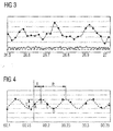
- Figure 3 shows a diagram of raw measurement values of the pressure (ordinate) measured over time (abscissa) interconnected by a line.
- a static ambient pressure in a windless condition bottom - dashed line
- a total static pressure as a sum of the static ambient pressure and a wind pressure measured by a static measurement device 3 t medium (ca. 10 m/s) to low (ca. 0,1-1 m/s) ambient wind speeds
- a total dynamic pressure as a sum of the static ambient pressure and the induced dynamic wind pressure measured by a rotating measurement device 3 (top - dotted line) at medium to low ambient wind speeds.
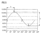
- Figure 4 shows a diagram of a smoothened sine wave plotted by the processing unit 15 based on measurement values (diamond shaped dots) of the rotating measurement device 3. Since in this case, the wind speed is measured by the measurement device 3, i.e. a pitot-tube anemometer, via a change in pressure, an amplitude Y, i.e. a difference between a maximum and a minimum measurement value, of the sine wave for one revolution R of the measurement device 3 around the axis 7 indicates the ambient wind speed, while a phase X of sine wave indicates the ambient wind direction.
- the respective positions A-D explained above with reference to Figure 2 are also indicated on the sine wave in this Figure 4 .
- Figure 5 shows a diagram of a section of a sine wave during one revolution R of the measurement device 3 around the axis 7 such as the one from Figure 4 , with the pressure (ordinate) measured over an angle of rotation of the measurement device around the axis (abscissa).
- the static ambient pressure bottom - dashed line
- an induced dynamic wind pressure induced by the rotation of the measurement device 3 around an axis 7, an amplification of the signal is achieved such that even in medium to low ambient wind speeds a reliable measurement and subsequent determination of an ambient wind speed and/or an ambient wind direction can be performed.
- the respective positions A-D explained above with reference to Figure 2 are also indicated on the sine wave in this Figure 5 .
- a measurement device 3 e.g. a vane, which measures a wind direction instead of a wind speed
- the centrifugal force together with the induced dynamic wind caused by the rotation of the measurement device 3 around the axis 7 leads to a specific orientation of the measurement device 3 relative to the axis 7, which orientation remains constant as long as there is no ambient wind. If there is an ambient wind, the orientation of the measurement device 3 will change cyclically, e.g. at each of the measurement positions (A-D), depending on the wind speed and the wind direction of the ambient wind additionally acting on the measurement device 3. In this case, the determination of an ambient wind speed and/or an ambient wind direction is analog to the previous embodiment.
Landscapes
- Engineering & Computer Science (AREA)
- Aviation & Aerospace Engineering (AREA)
- Physics & Mathematics (AREA)
- General Physics & Mathematics (AREA)
- Indicating Or Recording The Presence, Absence, Or Direction Of Movement (AREA)
Priority Applications (2)
| Application Number | Priority Date | Filing Date | Title |
|---|---|---|---|
| EP16171439.9A EP3249412A1 (fr) | 2016-05-25 | 2016-05-25 | Appareil et procédé pour mesurer une propriété de vent |
| PCT/EP2017/062586 WO2017202938A1 (fr) | 2016-05-25 | 2017-05-24 | Appareil et procédé de mesure d'une propriété du vent |
Applications Claiming Priority (1)
| Application Number | Priority Date | Filing Date | Title |
|---|---|---|---|
| EP16171439.9A EP3249412A1 (fr) | 2016-05-25 | 2016-05-25 | Appareil et procédé pour mesurer une propriété de vent |
Publications (1)
| Publication Number | Publication Date |
|---|---|
| EP3249412A1 true EP3249412A1 (fr) | 2017-11-29 |
Family
ID=56081326
Family Applications (1)
| Application Number | Title | Priority Date | Filing Date |
|---|---|---|---|
| EP16171439.9A Ceased EP3249412A1 (fr) | 2016-05-25 | 2016-05-25 | Appareil et procédé pour mesurer une propriété de vent |
Country Status (2)
| Country | Link |
|---|---|
| EP (1) | EP3249412A1 (fr) |
| WO (1) | WO2017202938A1 (fr) |
Citations (7)
| Publication number | Priority date | Publication date | Assignee | Title |
|---|---|---|---|---|
| DE325427C (de) * | 1919-02-26 | 1920-09-13 | Erdmann Steinorth | Stroemungsgeschwindigkeitsmesser |
| US3762876A (en) * | 1971-10-07 | 1973-10-02 | Honeywell Inc | Driven vane anemometers |
| US4065957A (en) * | 1976-11-15 | 1978-01-03 | Calspan Corporation | Fluid speed indicating apparatus and densitometer |
| US4074570A (en) * | 1977-03-15 | 1978-02-21 | Calspan Corporation | Fluid speed measuring apparatus |
| US4360888A (en) * | 1980-05-15 | 1982-11-23 | Pacer Systems, Inc. | Omnidirectional airspeed system |
| EP0763743A1 (fr) * | 1995-09-14 | 1997-03-19 | Gkn Westland Helicopters Limited | Procédé et dispositif pour la mesure de la vélocité de l'air d'un giravion |
| US20100154528A1 (en) * | 2008-12-23 | 2010-06-24 | Thales | Aerodynamic Measurement Probe and Helicopter Equipped with the Probe |
-
2016
- 2016-05-25 EP EP16171439.9A patent/EP3249412A1/fr not_active Ceased
-
2017
- 2017-05-24 WO PCT/EP2017/062586 patent/WO2017202938A1/fr not_active Ceased
Patent Citations (7)
| Publication number | Priority date | Publication date | Assignee | Title |
|---|---|---|---|---|
| DE325427C (de) * | 1919-02-26 | 1920-09-13 | Erdmann Steinorth | Stroemungsgeschwindigkeitsmesser |
| US3762876A (en) * | 1971-10-07 | 1973-10-02 | Honeywell Inc | Driven vane anemometers |
| US4065957A (en) * | 1976-11-15 | 1978-01-03 | Calspan Corporation | Fluid speed indicating apparatus and densitometer |
| US4074570A (en) * | 1977-03-15 | 1978-02-21 | Calspan Corporation | Fluid speed measuring apparatus |
| US4360888A (en) * | 1980-05-15 | 1982-11-23 | Pacer Systems, Inc. | Omnidirectional airspeed system |
| EP0763743A1 (fr) * | 1995-09-14 | 1997-03-19 | Gkn Westland Helicopters Limited | Procédé et dispositif pour la mesure de la vélocité de l'air d'un giravion |
| US20100154528A1 (en) * | 2008-12-23 | 2010-06-24 | Thales | Aerodynamic Measurement Probe and Helicopter Equipped with the Probe |
Also Published As
| Publication number | Publication date |
|---|---|
| WO2017202938A1 (fr) | 2017-11-30 |
Similar Documents
| Publication | Publication Date | Title |
|---|---|---|
| ES2822571T3 (es) | Sensor de error de guiñada, turbina eólica y ajuste de ángulo de guiñada | |
| US8813581B2 (en) | Force measuring system, method for measuring forces and torques on a rotating body and wind tunnel with a model arranged therein and comprising at least one propeller with a force measuring system | |
| EP2749766B1 (fr) | Procédé de détection d'un taux d'erreur de lacet d'une éolienne | |
| CN103917777B (zh) | 用来确定塔楼斜度的方法 | |
| ES2874485T3 (es) | Procedimiento y aparato para medir el estado del flujo de aire en una pala de turbina eólica | |
| KR101806139B1 (ko) | 멀티로터 성능 평가용 시험장치 | |
| JP4487059B2 (ja) | 風力タービンによって体験される風速および風向を決定する装置および方法 | |
| US8261609B2 (en) | Aerodynamic measurement probe and helicopter equipped with the probe | |
| RU2016104110A (ru) | Система и способ определения перемещений и колебаний подвижных структур | |
| CN103003565A (zh) | 用于确定风力涡轮机的转子叶片的弯曲角的方法和装置 | |
| CN101929426A (zh) | 控制风力涡轮机偏航的装置和方法 | |
| JP2010286483A5 (fr) | ||
| CN102128645A (zh) | 用于光电轴角编码器动态测角误差检测仪 | |
| CN102141371A (zh) | 用于确定传感器装置和磁场之间的角度的角度传感器和方法 | |
| CN110546463A (zh) | 用于确定旋转构件、尤其用于车辆的离合器操纵系统的电动机的角位置的方法 | |
| US20120232808A1 (en) | Propeller system with two counter-rotating propellers, a method for measuring the thrust of a propeller system with two counter-rotating propellers and wind tunnel with a model positioned therein having a propeller system | |
| KR20160032585A (ko) | 하이브리드 풍향풍속계 | |
| CN110006590A (zh) | 获取转子的不平衡量和平衡机的不平衡量的方法 | |
| CN101798793A (zh) | 一种车载式大波浪路形测量方法及其测量系统 | |
| CN104090126A (zh) | 一种加速度计带宽的测试方法 | |
| JP2016031352A5 (fr) | ||
| EP3249412A1 (fr) | Appareil et procédé pour mesurer une propriété de vent | |
| CN109915330A (zh) | 一种应用重力加速度传感器测量风机轮毂转速的方法 | |
| JP4153622B2 (ja) | 地盤振動測定方法及び測定システム | |
| KR20150013598A (ko) | 배기가스 터보차저 |
Legal Events
| Date | Code | Title | Description |
|---|---|---|---|
| STAA | Information on the status of an ep patent application or granted ep patent |
Free format text: STATUS: EXAMINATION IS IN PROGRESS |
|
| PUAI | Public reference made under article 153(3) epc to a published international application that has entered the european phase |
Free format text: ORIGINAL CODE: 0009012 |
|
| 17P | Request for examination filed |
Effective date: 20160920 |
|
| AK | Designated contracting states |
Kind code of ref document: A1 Designated state(s): AL AT BE BG CH CY CZ DE DK EE ES FI FR GB GR HR HU IE IS IT LI LT LU LV MC MK MT NL NO PL PT RO RS SE SI SK SM TR |
|
| AX | Request for extension of the european patent |
Extension state: BA ME |
|
| STAA | Information on the status of an ep patent application or granted ep patent |
Free format text: STATUS: THE APPLICATION HAS BEEN REFUSED |
|
| RAP1 | Party data changed (applicant data changed or rights of an application transferred) |
Owner name: AIRBUS DEFENCE AND SPACE GMBH |
|
| 18R | Application refused |
Effective date: 20180211 |