EP3249657A1 - Bande d'isolation, machine électrique et procédé de production d'une bande d'isolation et de la machine électrique - Google Patents
Bande d'isolation, machine électrique et procédé de production d'une bande d'isolation et de la machine électrique Download PDFInfo
- Publication number
- EP3249657A1 EP3249657A1 EP16170762.5A EP16170762A EP3249657A1 EP 3249657 A1 EP3249657 A1 EP 3249657A1 EP 16170762 A EP16170762 A EP 16170762A EP 3249657 A1 EP3249657 A1 EP 3249657A1
- Authority
- EP
- European Patent Office
- Prior art keywords
- insulating tape
- carrier fabric
- weft threads
- electrical conductor
- transverse direction
- Prior art date
- Legal status (The legal status is an assumption and is not a legal conclusion. Google has not performed a legal analysis and makes no representation as to the accuracy of the status listed.)
- Withdrawn
Links
- 238000004519 manufacturing process Methods 0.000 title claims description 10
- 238000009413 insulation Methods 0.000 title abstract description 44
- 239000004744 fabric Substances 0.000 claims abstract description 68
- 239000003365 glass fiber Substances 0.000 claims abstract description 15
- 239000010445 mica Substances 0.000 claims abstract description 12
- 229910052618 mica group Inorganic materials 0.000 claims abstract description 12
- 239000004020 conductor Substances 0.000 claims description 67
- 239000011230 binding agent Substances 0.000 claims description 22
- 229920005989 resin Polymers 0.000 claims description 18
- 239000011347 resin Substances 0.000 claims description 18
- 239000000463 material Substances 0.000 claims description 16
- PNEYBMLMFCGWSK-UHFFFAOYSA-N aluminium oxide Inorganic materials [O-2].[O-2].[O-2].[Al+3].[Al+3] PNEYBMLMFCGWSK-UHFFFAOYSA-N 0.000 claims description 11
- 239000013013 elastic material Substances 0.000 claims description 11
- 239000000835 fiber Substances 0.000 claims description 10
- 238000000034 method Methods 0.000 claims description 8
- 229920005594 polymer fiber Polymers 0.000 claims description 4
- 238000009941 weaving Methods 0.000 claims description 4
- 229920002334 Spandex Polymers 0.000 claims description 3
- 238000001816 cooling Methods 0.000 claims description 3
- 238000010438 heat treatment Methods 0.000 claims description 3
- 238000005470 impregnation Methods 0.000 claims description 3
- 229920000728 polyester Polymers 0.000 claims description 3
- 230000005670 electromagnetic radiation Effects 0.000 claims description 2
- 238000004513 sizing Methods 0.000 claims description 2
- 239000004952 Polyamide Substances 0.000 claims 1
- 239000004743 Polypropylene Substances 0.000 claims 1
- 229920002647 polyamide Polymers 0.000 claims 1
- -1 polypropylene Polymers 0.000 claims 1
- 229920001155 polypropylene Polymers 0.000 claims 1
- 239000004810 polytetrafluoroethylene Substances 0.000 claims 1
- 229920001343 polytetrafluoroethylene Polymers 0.000 claims 1
- 239000003822 epoxy resin Substances 0.000 description 3
- 229920000647 polyepoxide Polymers 0.000 description 3
- 239000000853 adhesive Substances 0.000 description 2
- 230000001070 adhesive effect Effects 0.000 description 2
- 210000001520 comb Anatomy 0.000 description 2
- 238000010586 diagram Methods 0.000 description 2
- 150000002118 epoxides Chemical class 0.000 description 2
- 238000002955 isolation Methods 0.000 description 2
- 229920003986 novolac Polymers 0.000 description 2
- 229920002689 polyvinyl acetate Polymers 0.000 description 2
- 239000011118 polyvinyl acetate Substances 0.000 description 2
- 238000004804 winding Methods 0.000 description 2
- MUTGBJKUEZFXGO-OLQVQODUSA-N (3as,7ar)-3a,4,5,6,7,7a-hexahydro-2-benzofuran-1,3-dione Chemical compound C1CCC[C@@H]2C(=O)OC(=O)[C@@H]21 MUTGBJKUEZFXGO-OLQVQODUSA-N 0.000 description 1
- LCFVJGUPQDGYKZ-UHFFFAOYSA-N Bisphenol A diglycidyl ether Chemical compound C=1C=C(OCC2OC2)C=CC=1C(C)(C)C(C=C1)=CC=C1OCC1CO1 LCFVJGUPQDGYKZ-UHFFFAOYSA-N 0.000 description 1
- LGRFSURHDFAFJT-UHFFFAOYSA-N Phthalic anhydride Natural products C1=CC=C2C(=O)OC(=O)C2=C1 LGRFSURHDFAFJT-UHFFFAOYSA-N 0.000 description 1
- XUCHXOAWJMEFLF-UHFFFAOYSA-N bisphenol F diglycidyl ether Chemical compound C1OC1COC(C=C1)=CC=C1CC(C=C1)=CC=C1OCC1CO1 XUCHXOAWJMEFLF-UHFFFAOYSA-N 0.000 description 1
- JHIWVOJDXOSYLW-UHFFFAOYSA-N butyl 2,2-difluorocyclopropane-1-carboxylate Chemical compound CCCCOC(=O)C1CC1(F)F JHIWVOJDXOSYLW-UHFFFAOYSA-N 0.000 description 1
- 150000001244 carboxylic acid anhydrides Chemical class 0.000 description 1
- 238000010292 electrical insulation Methods 0.000 description 1
- 238000001914 filtration Methods 0.000 description 1
- 239000000155 melt Substances 0.000 description 1
- VYKXQOYUCMREIS-UHFFFAOYSA-N methylhexahydrophthalic anhydride Chemical compound C1CCCC2C(=O)OC(=O)C21C VYKXQOYUCMREIS-UHFFFAOYSA-N 0.000 description 1
- 238000002791 soaking Methods 0.000 description 1
- 238000005507 spraying Methods 0.000 description 1
- 230000007704 transition Effects 0.000 description 1
- BPSIOYPQMFLKFR-UHFFFAOYSA-N trimethoxy-[3-(oxiran-2-ylmethoxy)propyl]silane Chemical compound CO[Si](OC)(OC)CCCOCC1CO1 BPSIOYPQMFLKFR-UHFFFAOYSA-N 0.000 description 1
Images


Classifications
-
- H—ELECTRICITY
- H01—ELECTRIC ELEMENTS
- H01B—CABLES; CONDUCTORS; INSULATORS; SELECTION OF MATERIALS FOR THEIR CONDUCTIVE, INSULATING OR DIELECTRIC PROPERTIES
- H01B3/00—Insulators or insulating bodies characterised by the insulating materials; Selection of materials for their insulating or dielectric properties
- H01B3/02—Insulators or insulating bodies characterised by the insulating materials; Selection of materials for their insulating or dielectric properties mainly consisting of inorganic substances
- H01B3/08—Insulators or insulating bodies characterised by the insulating materials; Selection of materials for their insulating or dielectric properties mainly consisting of inorganic substances quartz; glass; glass wool; slag wool; vitreous enamels
- H01B3/088—Shaping of glass or deposition of glass
-
- B—PERFORMING OPERATIONS; TRANSPORTING
- B32—LAYERED PRODUCTS
- B32B—LAYERED PRODUCTS, i.e. PRODUCTS BUILT-UP OF STRATA OF FLAT OR NON-FLAT, e.g. CELLULAR OR HONEYCOMB, FORM
- B32B27/00—Layered products comprising a layer of synthetic resin
- B32B27/06—Layered products comprising a layer of synthetic resin as the main or only constituent of a layer, which is next to another layer of the same or of a different material
- B32B27/08—Layered products comprising a layer of synthetic resin as the main or only constituent of a layer, which is next to another layer of the same or of a different material of synthetic resin
-
- B—PERFORMING OPERATIONS; TRANSPORTING
- B32—LAYERED PRODUCTS
- B32B—LAYERED PRODUCTS, i.e. PRODUCTS BUILT-UP OF STRATA OF FLAT OR NON-FLAT, e.g. CELLULAR OR HONEYCOMB, FORM
- B32B29/00—Layered products comprising a layer of paper or cardboard
- B32B29/02—Layered products comprising a layer of paper or cardboard next to a fibrous or filamentary layer
-
- B—PERFORMING OPERATIONS; TRANSPORTING
- B32—LAYERED PRODUCTS
- B32B—LAYERED PRODUCTS, i.e. PRODUCTS BUILT-UP OF STRATA OF FLAT OR NON-FLAT, e.g. CELLULAR OR HONEYCOMB, FORM
- B32B3/00—Layered products comprising a layer with external or internal discontinuities or unevennesses, or a layer of non-planar shape; Layered products comprising a layer having particular features of form
- B32B3/02—Layered products comprising a layer with external or internal discontinuities or unevennesses, or a layer of non-planar shape; Layered products comprising a layer having particular features of form characterised by features of form at particular places, e.g. in edge regions
-
- B—PERFORMING OPERATIONS; TRANSPORTING
- B32—LAYERED PRODUCTS
- B32B—LAYERED PRODUCTS, i.e. PRODUCTS BUILT-UP OF STRATA OF FLAT OR NON-FLAT, e.g. CELLULAR OR HONEYCOMB, FORM
- B32B5/00—Layered products characterised by the non- homogeneity or physical structure, i.e. comprising a fibrous, filamentary, particulate or foam layer; Layered products characterised by having a layer differing constitutionally or physically in different parts
- B32B5/22—Layered products characterised by the non- homogeneity or physical structure, i.e. comprising a fibrous, filamentary, particulate or foam layer; Layered products characterised by having a layer differing constitutionally or physically in different parts characterised by the presence of two or more layers which are next to each other and are fibrous, filamentary, formed of particles or foamed
- B32B5/24—Layered products characterised by the non- homogeneity or physical structure, i.e. comprising a fibrous, filamentary, particulate or foam layer; Layered products characterised by having a layer differing constitutionally or physically in different parts characterised by the presence of two or more layers which are next to each other and are fibrous, filamentary, formed of particles or foamed one layer being a fibrous or filamentary layer
- B32B5/26—Layered products characterised by the non- homogeneity or physical structure, i.e. comprising a fibrous, filamentary, particulate or foam layer; Layered products characterised by having a layer differing constitutionally or physically in different parts characterised by the presence of two or more layers which are next to each other and are fibrous, filamentary, formed of particles or foamed one layer being a fibrous or filamentary layer another layer next to it also being fibrous or filamentary
-
- B—PERFORMING OPERATIONS; TRANSPORTING
- B32—LAYERED PRODUCTS
- B32B—LAYERED PRODUCTS, i.e. PRODUCTS BUILT-UP OF STRATA OF FLAT OR NON-FLAT, e.g. CELLULAR OR HONEYCOMB, FORM
- B32B7/00—Layered products characterised by the relation between layers; Layered products characterised by the relative orientation of features between layers, or by the relative values of a measurable parameter between layers, i.e. products comprising layers having different physical, chemical or physicochemical properties; Layered products characterised by the interconnection of layers
- B32B7/04—Interconnection of layers
- B32B7/12—Interconnection of layers using interposed adhesives or interposed materials with bonding properties
-
- H—ELECTRICITY
- H01—ELECTRIC ELEMENTS
- H01B—CABLES; CONDUCTORS; INSULATORS; SELECTION OF MATERIALS FOR THEIR CONDUCTIVE, INSULATING OR DIELECTRIC PROPERTIES
- H01B3/00—Insulators or insulating bodies characterised by the insulating materials; Selection of materials for their insulating or dielectric properties
- H01B3/002—Inhomogeneous material in general
- H01B3/006—Other inhomogeneous material
-
- H—ELECTRICITY
- H01—ELECTRIC ELEMENTS
- H01B—CABLES; CONDUCTORS; INSULATORS; SELECTION OF MATERIALS FOR THEIR CONDUCTIVE, INSULATING OR DIELECTRIC PROPERTIES
- H01B3/00—Insulators or insulating bodies characterised by the insulating materials; Selection of materials for their insulating or dielectric properties
- H01B3/02—Insulators or insulating bodies characterised by the insulating materials; Selection of materials for their insulating or dielectric properties mainly consisting of inorganic substances
- H01B3/04—Insulators or insulating bodies characterised by the insulating materials; Selection of materials for their insulating or dielectric properties mainly consisting of inorganic substances mica
-
- H—ELECTRICITY
- H01—ELECTRIC ELEMENTS
- H01B—CABLES; CONDUCTORS; INSULATORS; SELECTION OF MATERIALS FOR THEIR CONDUCTIVE, INSULATING OR DIELECTRIC PROPERTIES
- H01B3/00—Insulators or insulating bodies characterised by the insulating materials; Selection of materials for their insulating or dielectric properties
- H01B3/02—Insulators or insulating bodies characterised by the insulating materials; Selection of materials for their insulating or dielectric properties mainly consisting of inorganic substances
- H01B3/08—Insulators or insulating bodies characterised by the insulating materials; Selection of materials for their insulating or dielectric properties mainly consisting of inorganic substances quartz; glass; glass wool; slag wool; vitreous enamels
- H01B3/082—Wires with glass or glass wool
-
- H—ELECTRICITY
- H02—GENERATION; CONVERSION OR DISTRIBUTION OF ELECTRIC POWER
- H02K—DYNAMO-ELECTRIC MACHINES
- H02K3/00—Details of windings
- H02K3/32—Windings characterised by the shape, form or construction of the insulation
-
- B—PERFORMING OPERATIONS; TRANSPORTING
- B32—LAYERED PRODUCTS
- B32B—LAYERED PRODUCTS, i.e. PRODUCTS BUILT-UP OF STRATA OF FLAT OR NON-FLAT, e.g. CELLULAR OR HONEYCOMB, FORM
- B32B2255/00—Coating on the layer surface
- B32B2255/02—Coating on the layer surface on fibrous or filamentary layer
-
- B—PERFORMING OPERATIONS; TRANSPORTING
- B32—LAYERED PRODUCTS
- B32B—LAYERED PRODUCTS, i.e. PRODUCTS BUILT-UP OF STRATA OF FLAT OR NON-FLAT, e.g. CELLULAR OR HONEYCOMB, FORM
- B32B2255/00—Coating on the layer surface
- B32B2255/20—Inorganic coating
-
- B—PERFORMING OPERATIONS; TRANSPORTING
- B32—LAYERED PRODUCTS
- B32B—LAYERED PRODUCTS, i.e. PRODUCTS BUILT-UP OF STRATA OF FLAT OR NON-FLAT, e.g. CELLULAR OR HONEYCOMB, FORM
- B32B2260/00—Layered product comprising an impregnated, embedded, or bonded layer wherein the layer comprises an impregnation, embedding, or binder material
- B32B2260/02—Composition of the impregnated, bonded or embedded layer
- B32B2260/021—Fibrous or filamentary layer
-
- B—PERFORMING OPERATIONS; TRANSPORTING
- B32—LAYERED PRODUCTS
- B32B—LAYERED PRODUCTS, i.e. PRODUCTS BUILT-UP OF STRATA OF FLAT OR NON-FLAT, e.g. CELLULAR OR HONEYCOMB, FORM
- B32B2260/00—Layered product comprising an impregnated, embedded, or bonded layer wherein the layer comprises an impregnation, embedding, or binder material
- B32B2260/04—Impregnation, embedding, or binder material
- B32B2260/046—Synthetic resin
-
- B—PERFORMING OPERATIONS; TRANSPORTING
- B32—LAYERED PRODUCTS
- B32B—LAYERED PRODUCTS, i.e. PRODUCTS BUILT-UP OF STRATA OF FLAT OR NON-FLAT, e.g. CELLULAR OR HONEYCOMB, FORM
- B32B2262/00—Composition or structural features of fibres which form a fibrous or filamentary layer or are present as additives
- B32B2262/02—Synthetic macromolecular fibres
-
- B—PERFORMING OPERATIONS; TRANSPORTING
- B32—LAYERED PRODUCTS
- B32B—LAYERED PRODUCTS, i.e. PRODUCTS BUILT-UP OF STRATA OF FLAT OR NON-FLAT, e.g. CELLULAR OR HONEYCOMB, FORM
- B32B2262/00—Composition or structural features of fibres which form a fibrous or filamentary layer or are present as additives
- B32B2262/02—Synthetic macromolecular fibres
- B32B2262/0253—Polyolefin fibres
-
- B—PERFORMING OPERATIONS; TRANSPORTING
- B32—LAYERED PRODUCTS
- B32B—LAYERED PRODUCTS, i.e. PRODUCTS BUILT-UP OF STRATA OF FLAT OR NON-FLAT, e.g. CELLULAR OR HONEYCOMB, FORM
- B32B2262/00—Composition or structural features of fibres which form a fibrous or filamentary layer or are present as additives
- B32B2262/02—Synthetic macromolecular fibres
- B32B2262/0261—Polyamide fibres
-
- B—PERFORMING OPERATIONS; TRANSPORTING
- B32—LAYERED PRODUCTS
- B32B—LAYERED PRODUCTS, i.e. PRODUCTS BUILT-UP OF STRATA OF FLAT OR NON-FLAT, e.g. CELLULAR OR HONEYCOMB, FORM
- B32B2262/00—Composition or structural features of fibres which form a fibrous or filamentary layer or are present as additives
- B32B2262/02—Synthetic macromolecular fibres
- B32B2262/0276—Polyester fibres
-
- B—PERFORMING OPERATIONS; TRANSPORTING
- B32—LAYERED PRODUCTS
- B32B—LAYERED PRODUCTS, i.e. PRODUCTS BUILT-UP OF STRATA OF FLAT OR NON-FLAT, e.g. CELLULAR OR HONEYCOMB, FORM
- B32B2262/00—Composition or structural features of fibres which form a fibrous or filamentary layer or are present as additives
- B32B2262/10—Inorganic fibres
- B32B2262/101—Glass fibres
-
- B—PERFORMING OPERATIONS; TRANSPORTING
- B32—LAYERED PRODUCTS
- B32B—LAYERED PRODUCTS, i.e. PRODUCTS BUILT-UP OF STRATA OF FLAT OR NON-FLAT, e.g. CELLULAR OR HONEYCOMB, FORM
- B32B2307/00—Properties of the layers or laminate
- B32B2307/20—Properties of the layers or laminate having particular electrical or magnetic properties, e.g. piezoelectric
- B32B2307/206—Insulating
-
- B—PERFORMING OPERATIONS; TRANSPORTING
- B32—LAYERED PRODUCTS
- B32B—LAYERED PRODUCTS, i.e. PRODUCTS BUILT-UP OF STRATA OF FLAT OR NON-FLAT, e.g. CELLULAR OR HONEYCOMB, FORM
- B32B2405/00—Adhesive articles, e.g. adhesive tapes
Definitions
- An electrical machine such as a motor or a generator, has a stator with grooves, in which a winding electrical conductors is inserted.
- the electric machine also has an electrical insulation system which has the purpose of electrically insulating the conductors against each other, against the stator and against the environment.
- the insulation system has an insulation tape wound around the conductors.
- the electrical conductors heat up. Heat conduction transfers heat from the electrical conductors to the insulation system. Because the insulation system and the electrical conductors have a different coefficient of expansion, both the insulation system and the electrical conductors are mechanically stressed during heating. This stress depends in particular on the temperatures occurring during operation of the electrical machine and the length of the electrical conductors.
- the object of the invention is therefore to provide an insulating tape for an electrical machine, the electric machine, a method for producing the insulating tape and a method for producing the electrical machine, wherein with the insulating tape, the mechanical stress of the electrical machine and in particular their isolation system can be reduced is.
- the electrical machine insulation tape according to the invention comprises a carrier fabric comprising warp threads extending in the longitudinal direction of the insulation tape and comprising glass fibers. and in the transverse direction of the insulating tape extending weft threads, and a partially discharge resistant material, in particular mica and / or alumina, having paper, which is adhesively bonded flat with the carrier fabric, wherein the weft threads are arranged meandering, so that the insulating tape in a in the Transverse direction stretched state is feasible.
- a carrier fabric comprising warp threads extending in the longitudinal direction of the insulation tape and comprising glass fibers. and in the transverse direction of the insulating tape extending weft threads, and a partially discharge resistant material, in particular mica and / or alumina, having paper, which is adhesively bonded flat with the carrier fabric, wherein the weft threads are arranged meandering, so that the insulating tape in a in the Transverse direction stretched state is feasible.
- an insulating system having the insulation tape can expand together with an electrical conductor of the electrical machine during operation of an electrical system having the insulation system, without excessive mechanical stresses and thus excessive mechanical stress occurring in the insulation system and in the electrical conductor , This makes it possible to operate the electric machine at a higher temperature than a conventional electric machine. In addition, it is possible to make the electrical conductors longer than is the case with the conventional electric machine.
- two adjacent weft threads are always mirrored in a direction oriented in the transverse axis to each other. This advantageously ensures that the carrier fabric does not warp in total.
- the meandering weft threads comprise the glass fibers.
- the glass fibers are not electrically conductive and are therefore suitable for use in the insulation tape.
- the glass fibers are less affected when an occurrence of partial discharges in the electric machine as is the case for example with polymer fibers, so that the insulation tape has a long life.
- the alternative electrical machine insulation tape according to the invention comprises a carrier fabric comprising warp threads extending in the longitudinal direction of the insulating tape and comprising glass fibers and in the transverse direction of the insulating tape extending weft threads, and a partially discharge resistant material, in particular mica and / or alumina, having paper, which is adhesively bonded flat with the carrier fabric, wherein the weft threads comprise an elastic material, so that the insulating tape can be converted into a stretched in the transverse direction state , Due to the elastic weft threads, an insulating system having the insulation tape can expand during operation of an electrical machine having the insulation system together with an electrical conductor of the electrical machine without excessive mechanical stresses and thus excessive mechanical stress occurring in the insulation system and in the electrical conductor. It is also possible with the alternative insulation tape according to the invention to operate the electric machine at a higher temperature and to provide longer electrical conductors, as is the case with a conventional electric machine.
- the elastic material comprises polymer fibers, in particular elastane fibers and / or polyester fibers.
- the weft threads are preferably arranged meander-shaped.
- the insulating tape can be stretched particularly far, whereby the mechanical stresses can be particularly well reduced.
- two adjacent weft threads are always mirrored in an oriented in the transverse direction axis to each other. This advantageously ensures that the carrier fabric does not warp in total.
- the electrical machine according to the invention has an electrical conductor and the insulating tape with the meandering weft threads, wherein the insulating tape is wound around the electrical conductor, that the transverse direction of the insulating tape substantially parallel to the axial direction of the electrical conductor and the longitudinal direction of the Insulation bands are oriented substantially parallel to the circumferential direction of the electrical conductor, wherein the insulating tape is arranged such that it can be transferred in the transversely stretched state or wherein the insulating tape is at least partially in the transversely stretched state and the carrier fabric of two adjacent turns of the wound around the electrical conductor insulating tape is in touching contact.
- the largest thermal expansion of the electrical conductor is to be expected in the axial direction of the electrical conductor.
- the carrier fabric By touch contact the carrier fabric can be glued to itself, by means of the adhesive used for bonding the carrier fabric with the partially discharge resistant material, in particular mica and / or alumina, paper used adhesive and / or by means of a impregnation tape impregnating impregnating resin.
- the strength of the insulation system can be increased in the radial direction.
- the alternative electric machine comprises an electrical conductor and an insulating tape, the weft threads of which comprise the elastic material, the insulating tape being wound around the electrical conductor such that the transverse direction of the insulating tape is substantially parallel to the axial direction of the electrical conductor and the longitudinal direction of the electrical conductor Isolation bands are oriented substantially parallel to the circumferential direction of the electrical conductor.
- the elastic weft threads parallel to the axial direction in order to reduce the mechanical stresses due to the different thermal expansions of the electrical conductor and the insulation system.
- the insulating tape is impregnated by a impregnating resin, wherein the impregnating resin is cured.
- the strength of the insulation system can be increased and also it is possible, in the event that the carrier fabric of two adjacent turns is in touching contact, the carrier fabric at the points of contact contact to adhere to itself.
- the method according to the invention for producing an insulating tape comprises the steps of: a) producing a carrier fabric having warp threads extending in the longitudinal direction of the insulating tape and comprising glass fibers, and weft threads extending in the transverse direction of the insulating tape such that the weft threads are meandered; b) adding a partially discharge-resistant material, in particular mica and / or alumina, paper to the carrier fabric or b) adding a partially discharge-resistant material, in particular mica and / or alumina, to the carrier fabric or b) connecting the carrier fabric to a layer comprising a partially discharge resistant material, in particular mica and / or alumina, has.
- the attachment of the paper to the carrier fabric can be done for example by means of a surface bonding, spraying and / or filtering.
- step a) when weaving the carrier fabric the weft threads are oscillated in a direction perpendicular to the transverse direction of the insulating tape. It is preferred that after weaving a size is applied to the carrier fabric, whereby the meandering weft threads are fixed.
- step a) comprises the following steps: a1) tensioning of the carrier fabric only in the longitudinal direction of the insulating band; a2) applying a hot binder inhomogeneous to the longitudinally strained backing fabric; a3) cooling the binder so that the binder contracts with the carrier fabric, thereby the weft threads meander meandering.
- the binder is applied by means of a roller.
- the binder may comprise, for example, BADGE, in particular having a molecular weight greater than 700 g / mol, novolak and / or polyvinyl acetate.
- the weft threads are arranged meandering in the carrier fabric by means of at least one comb and then the meandering arrangement of the weft threads is fixed by applying a size and / or a binder to the carrier fabric.
- the binder may, for example, BADGE, in particular having a molecular weight greater than 700 g / mol, novolac, polyvinyl acetate and / or a Silanschlichte, especially Glymo have.
- step a) a first size be applied to the warp threads and a second size to the weft threads, wherein the sizes are selected such that after application, the second size shrinks more than the first size, whereby arrange the weft threads meandering.
- the second size is chosen such that it melts in a subsequent soaking of a impregnating resin.
- the method according to the invention for producing an electrical machine comprises the steps of: c) providing the insulation band with the meandering weft threads; d) fixing the meandering arrangement of the weft threads in the insulating tape by applying a size and / or a binder; e) wrapping an electrical conductor with the insulating tape; f) impregnating the insulating tape with a impregnating resin, so that the sizing and / or the binder melt.
- An alternative method for producing an electrical machine comprises the steps of: c) providing the insulation band with the meandering weft threads; e) wrapping an electrical conductor with the insulating tape; e1) partial relaxation of the carrier fabric, so that the carrier fabric of two adjacent turns at joints forms a touch contact; f) impregnation of the insulating tape with a impregnating resin, so that the carrier fabric adhered to the joints. Due to the glued joints, the insulation system has a high strength in the radial direction. Due to the partial relaxation is advantageously achieved that the insulation system can stretch in the axial direction.
- FIG. 1 shows a method for producing the insulating tape 1, in which the carrier fabric 2 and the partially discharge-resistant material having paper 3 are adhesively bonded to each other by means of a binder resin.
- the binder resin can be, for example, BADGE, in particular with a molecular weight greater than 700 g / mol.
- the base fabric 2 and the paper 3 having the partial-discharge-resistant material have the same length and the same width in the insulating tape 1. After bonding the carrier fabric 2 and the paper 3 having the partially-discharge-resistant material, the insulating tape 1 can be cut in the longitudinal direction 3, so that two of the insulating tapes 1 are formed with a shorter width.
- FIGS. 1, 2 and 5 show that in the carrier fabric 2, two adjacent weft threads 7 are always mirrored in an axis oriented in the transverse direction 5 axis to each other. This ensures that the carrier fabric 2 does not warp overall.
- FIG. 2 shows an electrical conductor 8 for the electric machine.
- the electric machine has the insulation tape 1 which is wound around the electrical conductor 8 such that the longitudinal direction 4 of the insulation tape 1 encloses an angle of 3 ° to 10 ° with the circumferential direction 18 of the electrical conductor 8.
- the transverse direction 5 of the insulating tape 1 are substantially parallel to the axial direction 16 of the electrical conductor 8 and the longitudinal direction. 4 of the insulating tape oriented substantially parallel to the circumferential direction 18 of the electrical conductor 8.
- the insulating tape 1 is impregnated by a impregnating resin, wherein the impregnating resin is cured. As a result, the insulating tape 1 forms an insulation system together with the impregnating resin.
- the impregnating resin may, for example, comprise an epoxy resin, in particular the epoxy resin has an epoxide, in particular a cycloaliphatic epoxide, in particular ECC and / or CY179, bisphenol A diglycidyl ether and / or bisphenol F diglycidyl ether.
- the epoxy resin may additionally comprise a carboxylic acid anhydride, in particular phthalic anhydride, methylhexahydrophthalic anhydride and / or hexahydrophthalic anhydride.
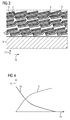
- FIG. 2 shows a first alternative for the electric machine, according to which the insulating tape 1 is arranged such that it can be transferred in the stretched in the transverse direction 5 state.
- the transfer to the extended state can be done, for example, during operation of the electric machine, when the electrical conductor 8 is heated and thus expands in particular in its axial direction 16.
- the weft threads 7 are arranged in such a meandering manner that upon expansion no slip between the electrical conductor and the insulation system is formed. As a result, the mechanical load, in particular insulation system during expansion of the electrical conductor 8 is low.
- FIG. 3 shows a second alternative for the electrical machine according to which the insulating tape 1 is at least partially in the stretched in the transverse direction 5 state and the carrier fabric 2 of two adjacent turns of the wound around the electrical conductor 8 insulating tape 1 at at least one connection point 9 in a touching contact stands.
- the bonding resin and / or the impregnating resin bonds the support fabric 2 to itself at the connection points. This results in increased strength of the insulation system in the radial direction 17 of the electrical conductor.
- Particularly advantageous is the joints 9 in areas of the electrical conductor 8 provide, in which it is curved.
- FIG. 4 a diagram is shown, on the ordinate 11 of the distance in the radial direction 17 of the electrical conductor 8 and over the abscissa 10 of the contact pressure 12 and the relaxation of the insulating strip 13 1 are plotted. It can be seen from the diagram that a low contact pressure 12 and a strong relaxation 13 of the insulating strip 1 are present in the outer layers of the insulating strip 1, which are associated with a large radial distance. In contrast, in the inner layers of the insulating tape 1, a high contact pressure 12 and a weak relaxation 13 before. Thus, the connection points 9, as it is in FIG. 3 is shown formed predominantly in the outer layers. In curved areas of the electrical conductors 8 arise at a thermal expansion of the electrical conductor 8 particularly strong forces in the outer layers. Therefore, it is particularly advantageous to provide the connection points 9 in the outer layers.
- an alternative insulation tape can have weft threads which have an elastic material, so that the insulation tape can be transferred into a stretched state in the transverse direction.
- the elastic material comprises polymer fibers, in particular elastane fibers and / or polyester fibers. The stretching takes place under an elongation of the weft threads.
- An alternative electric machine has an electrical conductor and the alternative insulation tape wound around the electrical conductor such that the longitudinal direction of the insulation tape encloses an angle of 3 ° to 10 ° with the circumferential direction of the electrical conductor.
- the transverse direction of the insulating tape substantially parallel to the axial direction of the electrical conductor and the longitudinal direction of the insulating tape are substantially parallel oriented to the circumferential direction of the electrical conductor.
- the transfer of the alternative insulation tape in the extended state for example, in the operation of the electrical machine happen when the electrical conductor heats up and thus expands in particular in its axial direction.
- the weft threads are so flexible by the elastic material that upon expansion no slip between the electrical conductor and the insulation system is formed.
- the method for producing the insulating tape 1 with the meander-shaped weft threads 7 comprises the steps of: a) producing a carrier fabric 2, the warp threads 6 running in the longitudinal direction 4 of the insulating tape 1 and having glass fibers, and extending in the transverse direction 5 of the insulating tape 1 Has weft threads 7, such that the weft threads 7 are arranged meandering; b) surface bonding of the carrier fabric 2 with a partially discharge-resistant material, in particular mica and / or alumina, having paper. 3
- step a) comprises the following steps: a1) tensioning the carrier fabric 2 only in the longitudinal direction 4 of the insulating tape 1; a2) application of a hot binder by means of a roller 14 inhomogeneous on the stretched in the longitudinal direction 4 carrier fabric 2; a3) cooling the binder, so that the binder contracts with the carrier fabric, whereby the weft threads meander.
- step a2) arranged in the transverse direction 5 rows of binding points 15 are applied, wherein adjacent rows always have a different number of binding points 15. This advantageously ensures that the weft threads 7 are arranged in a particularly meandering manner.
- step a) during weaving of the carrier fabric 2 the weft threads 7 oscillate in one Direction perpendicular to the transverse direction 5 of the insulating tape 1 moves.
- two adjacent weft threads 7 are always moved exactly opposite in phase. This ensures that in the carrier fabric 2, two adjacent weft threads 7 are always mirrored in an oriented in the transverse direction 5 axis to each other.
- step a) the weft threads 7 in the carrier fabric 2 are meandered by means of at least one comb and then the meandering arrangement of the weft threads 7 is fixed to the carrier fabric 2 by applying a size and / or a binder.
- two of the combs can engage one of the weft threads 7, wherein the combs offset from each other and in opposite directions deform a weft thread 7.
- a first size is applied to the warp yarns 6 and a second size is applied to the weft yarns 7, wherein the sizes are selected such that, after application, the second size will shrink more than the first size, thereby increasing the caliper Arrange weft threads meandering.
- step a) the carrier fabric is produced, wherein the warp threads have an auxetic material, and subsequently the warp threads are elongated by heating by means of electromagnetic radiation, whereby the weft threads 6 meander.
Landscapes
- Chemical & Material Sciences (AREA)
- Inorganic Chemistry (AREA)
- Engineering & Computer Science (AREA)
- Power Engineering (AREA)
- Insulating Bodies (AREA)
Priority Applications (2)
| Application Number | Priority Date | Filing Date | Title |
|---|---|---|---|
| EP16170762.5A EP3249657A1 (fr) | 2016-05-23 | 2016-05-23 | Bande d'isolation, machine électrique et procédé de production d'une bande d'isolation et de la machine électrique |
| PCT/EP2017/059491 WO2017202551A1 (fr) | 2016-05-23 | 2017-04-21 | Bande isolante, machine électrique et procédé pour fabriquer la bande isolante et la machine électrique |
Applications Claiming Priority (1)
| Application Number | Priority Date | Filing Date | Title |
|---|---|---|---|
| EP16170762.5A EP3249657A1 (fr) | 2016-05-23 | 2016-05-23 | Bande d'isolation, machine électrique et procédé de production d'une bande d'isolation et de la machine électrique |
Publications (1)
| Publication Number | Publication Date |
|---|---|
| EP3249657A1 true EP3249657A1 (fr) | 2017-11-29 |
Family
ID=56083938
Family Applications (1)
| Application Number | Title | Priority Date | Filing Date |
|---|---|---|---|
| EP16170762.5A Withdrawn EP3249657A1 (fr) | 2016-05-23 | 2016-05-23 | Bande d'isolation, machine électrique et procédé de production d'une bande d'isolation et de la machine électrique |
Country Status (2)
| Country | Link |
|---|---|
| EP (1) | EP3249657A1 (fr) |
| WO (1) | WO2017202551A1 (fr) |
Cited By (2)
| Publication number | Priority date | Publication date | Assignee | Title |
|---|---|---|---|---|
| DE102019202420A1 (de) * | 2019-02-22 | 2020-08-27 | Siemens Aktiengesellschaft | Verfahren zum zerstörungsfreien Detektieren von Alterungserscheinungen eines regelmäßig wiederkehrende Strukturen aufweisenden Bauteils |
| US12055612B2 (en) | 2022-05-12 | 2024-08-06 | Joon Bu Park | Negative Poisson's ratio materials for energy absorption |
Citations (3)
| Publication number | Priority date | Publication date | Assignee | Title |
|---|---|---|---|---|
| US2679677A (en) * | 1951-10-30 | 1954-06-01 | Gen Electric | Woven glass electrical insulating sheet |
| EP0604804A2 (fr) * | 1992-12-28 | 1994-07-06 | Asea Brown Boveri Ag | Bande isolante et son procédé de fabrication |
| EP0878894A1 (fr) * | 1997-05-16 | 1998-11-18 | Abb Research Ltd. | Isolation d'un enroulement statorique |
-
2016
- 2016-05-23 EP EP16170762.5A patent/EP3249657A1/fr not_active Withdrawn
-
2017
- 2017-04-21 WO PCT/EP2017/059491 patent/WO2017202551A1/fr not_active Ceased
Patent Citations (3)
| Publication number | Priority date | Publication date | Assignee | Title |
|---|---|---|---|---|
| US2679677A (en) * | 1951-10-30 | 1954-06-01 | Gen Electric | Woven glass electrical insulating sheet |
| EP0604804A2 (fr) * | 1992-12-28 | 1994-07-06 | Asea Brown Boveri Ag | Bande isolante et son procédé de fabrication |
| EP0878894A1 (fr) * | 1997-05-16 | 1998-11-18 | Abb Research Ltd. | Isolation d'un enroulement statorique |
Cited By (3)
| Publication number | Priority date | Publication date | Assignee | Title |
|---|---|---|---|---|
| DE102019202420A1 (de) * | 2019-02-22 | 2020-08-27 | Siemens Aktiengesellschaft | Verfahren zum zerstörungsfreien Detektieren von Alterungserscheinungen eines regelmäßig wiederkehrende Strukturen aufweisenden Bauteils |
| US11940499B2 (en) | 2019-02-22 | 2024-03-26 | Siemens Energy Global GmbH &Co. KG | Method for the -destructive detecting of ageing symptoms of a component having regularly recurring structures |
| US12055612B2 (en) | 2022-05-12 | 2024-08-06 | Joon Bu Park | Negative Poisson's ratio materials for energy absorption |
Also Published As
| Publication number | Publication date |
|---|---|
| WO2017202551A1 (fr) | 2017-11-30 |
Similar Documents
| Publication | Publication Date | Title |
|---|---|---|
| DE3586693T2 (de) | Waermerueckstellbarer gegenstand. | |
| EP1154543B1 (fr) | Isolation d'enroulements statoriques par des manchons rétractables | |
| DE10353070B4 (de) | Verfahren und Vorrichtung zur Binderaktivierung auf einem Faserhalbzeug/Preform durch direktes Erwärmen von Kohlenstofffasern über eine angelegte elektrische Spannung | |
| CH677565A5 (fr) | ||
| DE1924505B2 (de) | Verfahren zum Herstellen von Gleitlagern | |
| EP2821198A1 (fr) | Tête d'amenée de semi-produit à base de fibres | |
| EP3938164A1 (fr) | Dispositif d'outil servant à fabriquer un composant en matériau composite, et procédé de fabrication d'un composant à partir d'un matériau composite | |
| EP2390885B1 (fr) | Procédé de fabrication d'enroulements pour un transformateur sec | |
| EP3249657A1 (fr) | Bande d'isolation, machine électrique et procédé de production d'une bande d'isolation et de la machine électrique | |
| EP2206128A1 (fr) | Procédé de production d'un enroulement de transformateur multicouche pourvu d'une couche d'isolation | |
| DE102016121693B4 (de) | Verfahren zum Herstellen eines Duroplast-Thermoplast-Verbundbauteils | |
| WO2018206231A1 (fr) | Fixation d'un fil de bandage pour fixer et positionner des aimants permanents | |
| DE102007057491A1 (de) | Bauteil mit Carbonanotubes | |
| WO2013139659A1 (fr) | Bande sans fin et procédé de fabrication d'une bande sans fin | |
| DE2443271C3 (de) | Schlauch mit einem Innenschlauch und mehreren Bewehrungslagen | |
| AT508878B1 (de) | Stator für eine elektromaschine, insbesondere für einen elektromotor | |
| DE3537142C2 (fr) | ||
| EP2915170B1 (fr) | Ensemble d'isolation pour une machine haute tension | |
| EP1147269B1 (fr) | Procede de production d'elements angulaires a base de lamelles de bande plate | |
| DE102016116788A1 (de) | Faserverbundbauteil und Verfahren zur Herstellung eines Faserverbundbauteils | |
| DE102005055290B3 (de) | Glimmerverstärkter Isolierschlauch | |
| DE102013007331A1 (de) | Elektrische Maschine sowie Verfahren zur Herstellung einer elektrischen Maschine | |
| DE1504586C3 (de) | Fadenverstärktes Harzband | |
| EP1453651B1 (fr) | Procede pour l'isolation d'enroulements de stator | |
| DE2450915A1 (de) | Verfahren zum herstellen drahtbewehrten, silikongummibeschichteten gewebes |
Legal Events
| Date | Code | Title | Description |
|---|---|---|---|
| PUAI | Public reference made under article 153(3) epc to a published international application that has entered the european phase |
Free format text: ORIGINAL CODE: 0009012 |
|
| AK | Designated contracting states |
Kind code of ref document: A1 Designated state(s): AL AT BE BG CH CY CZ DE DK EE ES FI FR GB GR HR HU IE IS IT LI LT LU LV MC MK MT NL NO PL PT RO RS SE SI SK SM TR |
|
| AX | Request for extension of the european patent |
Extension state: BA ME |
|
| STAA | Information on the status of an ep patent application or granted ep patent |
Free format text: STATUS: THE APPLICATION IS DEEMED TO BE WITHDRAWN |
|
| 18D | Application deemed to be withdrawn |
Effective date: 20180530 |