EP3249659A1 - Dispositif anti-effluves, machine electrique et procede de production de dispositif anti-effluves - Google Patents
Dispositif anti-effluves, machine electrique et procede de production de dispositif anti-effluves Download PDFInfo
- Publication number
- EP3249659A1 EP3249659A1 EP16170822.7A EP16170822A EP3249659A1 EP 3249659 A1 EP3249659 A1 EP 3249659A1 EP 16170822 A EP16170822 A EP 16170822A EP 3249659 A1 EP3249659 A1 EP 3249659A1
- Authority
- EP
- European Patent Office
- Prior art keywords
- microcapsules
- polymer resin
- corona protection
- corona
- protection according
- Prior art date
- Legal status (The legal status is an assumption and is not a legal conclusion. Google has not performed a legal analysis and makes no representation as to the accuracy of the status listed.)
- Withdrawn
Links
- 238000004519 manufacturing process Methods 0.000 title claims description 3
- 239000003094 microcapsule Substances 0.000 claims abstract description 59
- 239000002952 polymeric resin Substances 0.000 claims abstract description 52
- 229920003002 synthetic resin Polymers 0.000 claims abstract description 52
- 239000002245 particle Substances 0.000 claims abstract description 35
- 239000004922 lacquer Substances 0.000 claims abstract description 9
- 238000009413 insulation Methods 0.000 claims description 19
- 239000004020 conductor Substances 0.000 claims description 16
- 239000003973 paint Substances 0.000 claims description 16
- LFQSCWFLJHTTHZ-UHFFFAOYSA-N Ethanol Chemical compound CCO LFQSCWFLJHTTHZ-UHFFFAOYSA-N 0.000 claims description 12
- XEKOWRVHYACXOJ-UHFFFAOYSA-N Ethyl acetate Chemical compound CCOC(C)=O XEKOWRVHYACXOJ-UHFFFAOYSA-N 0.000 claims description 12
- IMNFDUFMRHMDMM-UHFFFAOYSA-N N-Heptane Chemical compound CCCCCCC IMNFDUFMRHMDMM-UHFFFAOYSA-N 0.000 claims description 12
- 229920001577 copolymer Polymers 0.000 claims description 12
- 239000000178 monomer Substances 0.000 claims description 10
- 239000002904 solvent Substances 0.000 claims description 10
- 239000002105 nanoparticle Substances 0.000 claims description 9
- KFZMGEQAYNKOFK-UHFFFAOYSA-N Isopropanol Chemical compound CC(C)O KFZMGEQAYNKOFK-UHFFFAOYSA-N 0.000 claims description 8
- OFBQJSOFQDEBGM-UHFFFAOYSA-N Pentane Chemical compound CCCCC OFBQJSOFQDEBGM-UHFFFAOYSA-N 0.000 claims description 8
- VLKZOEOYAKHREP-UHFFFAOYSA-N n-Hexane Chemical compound CCCCCC VLKZOEOYAKHREP-UHFFFAOYSA-N 0.000 claims description 8
- -1 polyethylene terephthalate Polymers 0.000 claims description 8
- BDERNNFJNOPAEC-UHFFFAOYSA-N propan-1-ol Chemical compound CCCO BDERNNFJNOPAEC-UHFFFAOYSA-N 0.000 claims description 8
- 239000004744 fabric Substances 0.000 claims description 7
- 238000000034 method Methods 0.000 claims description 7
- 229920000139 polyethylene terephthalate Polymers 0.000 claims description 5
- 239000005020 polyethylene terephthalate Substances 0.000 claims description 5
- 239000002966 varnish Substances 0.000 claims description 5
- 150000001335 aliphatic alkanes Chemical class 0.000 claims description 4
- NLHHRLWOUZZQLW-UHFFFAOYSA-N Acrylonitrile Chemical compound C=CC#N NLHHRLWOUZZQLW-UHFFFAOYSA-N 0.000 claims description 3
- 229910018072 Al 2 O 3 Inorganic materials 0.000 claims description 3
- OKTJSMMVPCPJKN-UHFFFAOYSA-N Carbon Chemical compound [C] OKTJSMMVPCPJKN-UHFFFAOYSA-N 0.000 claims description 3
- 239000004952 Polyamide Substances 0.000 claims description 3
- 239000004642 Polyimide Substances 0.000 claims description 3
- 239000004743 Polypropylene Substances 0.000 claims description 3
- 239000004793 Polystyrene Substances 0.000 claims description 3
- 229910004298 SiO 2 Inorganic materials 0.000 claims description 3
- 229910010413 TiO 2 Inorganic materials 0.000 claims description 3
- 239000006229 carbon black Substances 0.000 claims description 3
- 230000008020 evaporation Effects 0.000 claims description 3
- 238000001704 evaporation Methods 0.000 claims description 3
- WSFSSNUMVMOOMR-UHFFFAOYSA-N formaldehyde Substances O=C WSFSSNUMVMOOMR-UHFFFAOYSA-N 0.000 claims description 3
- 239000011521 glass Substances 0.000 claims description 3
- 229910002804 graphite Inorganic materials 0.000 claims description 3
- 239000010439 graphite Substances 0.000 claims description 3
- 239000000463 material Substances 0.000 claims description 3
- 229920000058 polyacrylate Polymers 0.000 claims description 3
- 229920002647 polyamide Polymers 0.000 claims description 3
- 229920000728 polyester Polymers 0.000 claims description 3
- 229920001721 polyimide Polymers 0.000 claims description 3
- 229920000642 polymer Polymers 0.000 claims description 3
- 229920001155 polypropylene Polymers 0.000 claims description 3
- 229920002223 polystyrene Polymers 0.000 claims description 3
- 239000004810 polytetrafluoroethylene Substances 0.000 claims description 3
- 229920001343 polytetrafluoroethylene Polymers 0.000 claims description 3
- 229920002635 polyurethane Polymers 0.000 claims description 3
- 239000004814 polyurethane Substances 0.000 claims description 3
- 125000005396 acrylic acid ester group Chemical group 0.000 claims 1
- 229920003235 aromatic polyamide Polymers 0.000 claims 1
- 239000011248 coating agent Substances 0.000 claims 1
- 238000000576 coating method Methods 0.000 claims 1
- 230000005684 electric field Effects 0.000 description 7
- NMFHJNAPXOMSRX-PUPDPRJKSA-N [(1r)-3-(3,4-dimethoxyphenyl)-1-[3-(2-morpholin-4-ylethoxy)phenyl]propyl] (2s)-1-[(2s)-2-(3,4,5-trimethoxyphenyl)butanoyl]piperidine-2-carboxylate Chemical compound C([C@@H](OC(=O)[C@@H]1CCCCN1C(=O)[C@@H](CC)C=1C=C(OC)C(OC)=C(OC)C=1)C=1C=C(OCCN2CCOCC2)C=CC=1)CC1=CC=C(OC)C(OC)=C1 NMFHJNAPXOMSRX-PUPDPRJKSA-N 0.000 description 4
- 239000004745 nonwoven fabric Substances 0.000 description 4
- 230000015572 biosynthetic process Effects 0.000 description 3
- 239000003505 polymerization initiator Substances 0.000 description 3
- NIXOWILDQLNWCW-UHFFFAOYSA-M Acrylate Chemical compound [O-]C(=O)C=C NIXOWILDQLNWCW-UHFFFAOYSA-M 0.000 description 2
- 239000003085 diluting agent Substances 0.000 description 2
- 239000012799 electrically-conductive coating Substances 0.000 description 2
- 239000000945 filler Substances 0.000 description 2
- 230000035876 healing Effects 0.000 description 2
- 239000012510 hollow fiber Substances 0.000 description 2
- 239000010954 inorganic particle Substances 0.000 description 2
- 239000007788 liquid Substances 0.000 description 2
- 239000000126 substance Substances 0.000 description 2
- UNMJLQGKEDTEKJ-UHFFFAOYSA-N (3-ethyloxetan-3-yl)methanol Chemical compound CCC1(CO)COC1 UNMJLQGKEDTEKJ-UHFFFAOYSA-N 0.000 description 1
- 230000009172 bursting Effects 0.000 description 1
- 239000011231 conductive filler Substances 0.000 description 1
- 238000000354 decomposition reaction Methods 0.000 description 1
- 230000003247 decreasing effect Effects 0.000 description 1
- 230000000593 degrading effect Effects 0.000 description 1
- 230000000694 effects Effects 0.000 description 1
- 238000007720 emulsion polymerization reaction Methods 0.000 description 1
- 150000002118 epoxides Chemical class 0.000 description 1
- 239000003822 epoxy resin Substances 0.000 description 1
- 230000003628 erosive effect Effects 0.000 description 1
- 238000005470 impregnation Methods 0.000 description 1
- 239000000203 mixture Substances 0.000 description 1
- 229920000647 polyepoxide Polymers 0.000 description 1
- 229920005989 resin Polymers 0.000 description 1
- 239000011347 resin Substances 0.000 description 1
- 238000004804 winding Methods 0.000 description 1
Images
Classifications
-
- H—ELECTRICITY
- H01—ELECTRIC ELEMENTS
- H01B—CABLES; CONDUCTORS; INSULATORS; SELECTION OF MATERIALS FOR THEIR CONDUCTIVE, INSULATING OR DIELECTRIC PROPERTIES
- H01B3/00—Insulators or insulating bodies characterised by the insulating materials; Selection of materials for their insulating or dielectric properties
- H01B3/002—Inhomogeneous material in general
- H01B3/004—Inhomogeneous material in general with conductive additives or conductive layers
-
- H—ELECTRICITY
- H02—GENERATION; CONVERSION OR DISTRIBUTION OF ELECTRIC POWER
- H02K—DYNAMO-ELECTRIC MACHINES
- H02K3/00—Details of windings
- H02K3/32—Windings characterised by the shape, form or construction of the insulation
- H02K3/40—Windings characterised by the shape, form or construction of the insulation for high voltage, e.g. affording protection against corona discharges
-
- C—CHEMISTRY; METALLURGY
- C09—DYES; PAINTS; POLISHES; NATURAL RESINS; ADHESIVES; COMPOSITIONS NOT OTHERWISE PROVIDED FOR; APPLICATIONS OF MATERIALS NOT OTHERWISE PROVIDED FOR
- C09D—COATING COMPOSITIONS, e.g. PAINTS, VARNISHES OR LACQUERS; FILLING PASTES; CHEMICAL PAINT OR INK REMOVERS; INKS; CORRECTING FLUIDS; WOODSTAINS; PASTES OR SOLIDS FOR COLOURING OR PRINTING; USE OF MATERIALS THEREFOR
- C09D4/00—Coating compositions, e.g. paints, varnishes or lacquers, based on organic non-macromolecular compounds having at least one polymerisable carbon-to-carbon unsaturated bond ; Coating compositions, based on monomers of macromolecular compounds of groups C09D183/00 - C09D183/16
- C09D4/06—Organic non-macromolecular compounds having at least one polymerisable carbon-to-carbon unsaturated bond in combination with a macromolecular compound other than an unsaturated polymer of groups C09D159/00 - C09D187/00
-
- C—CHEMISTRY; METALLURGY
- C09—DYES; PAINTS; POLISHES; NATURAL RESINS; ADHESIVES; COMPOSITIONS NOT OTHERWISE PROVIDED FOR; APPLICATIONS OF MATERIALS NOT OTHERWISE PROVIDED FOR
- C09D—COATING COMPOSITIONS, e.g. PAINTS, VARNISHES OR LACQUERS; FILLING PASTES; CHEMICAL PAINT OR INK REMOVERS; INKS; CORRECTING FLUIDS; WOODSTAINS; PASTES OR SOLIDS FOR COLOURING OR PRINTING; USE OF MATERIALS THEREFOR
- C09D5/00—Coating compositions, e.g. paints, varnishes or lacquers, characterised by their physical nature or the effects produced; Filling pastes
- C09D5/24—Electrically-conducting paints
-
- C—CHEMISTRY; METALLURGY
- C09—DYES; PAINTS; POLISHES; NATURAL RESINS; ADHESIVES; COMPOSITIONS NOT OTHERWISE PROVIDED FOR; APPLICATIONS OF MATERIALS NOT OTHERWISE PROVIDED FOR
- C09D—COATING COMPOSITIONS, e.g. PAINTS, VARNISHES OR LACQUERS; FILLING PASTES; CHEMICAL PAINT OR INK REMOVERS; INKS; CORRECTING FLUIDS; WOODSTAINS; PASTES OR SOLIDS FOR COLOURING OR PRINTING; USE OF MATERIALS THEREFOR
- C09D7/00—Features of coating compositions, not provided for in group C09D5/00; Processes for incorporating ingredients in coating compositions
- C09D7/40—Additives
-
- C—CHEMISTRY; METALLURGY
- C09—DYES; PAINTS; POLISHES; NATURAL RESINS; ADHESIVES; COMPOSITIONS NOT OTHERWISE PROVIDED FOR; APPLICATIONS OF MATERIALS NOT OTHERWISE PROVIDED FOR
- C09D—COATING COMPOSITIONS, e.g. PAINTS, VARNISHES OR LACQUERS; FILLING PASTES; CHEMICAL PAINT OR INK REMOVERS; INKS; CORRECTING FLUIDS; WOODSTAINS; PASTES OR SOLIDS FOR COLOURING OR PRINTING; USE OF MATERIALS THEREFOR
- C09D7/00—Features of coating compositions, not provided for in group C09D5/00; Processes for incorporating ingredients in coating compositions
- C09D7/40—Additives
- C09D7/65—Additives macromolecular
-
- C—CHEMISTRY; METALLURGY
- C09—DYES; PAINTS; POLISHES; NATURAL RESINS; ADHESIVES; COMPOSITIONS NOT OTHERWISE PROVIDED FOR; APPLICATIONS OF MATERIALS NOT OTHERWISE PROVIDED FOR
- C09D—COATING COMPOSITIONS, e.g. PAINTS, VARNISHES OR LACQUERS; FILLING PASTES; CHEMICAL PAINT OR INK REMOVERS; INKS; CORRECTING FLUIDS; WOODSTAINS; PASTES OR SOLIDS FOR COLOURING OR PRINTING; USE OF MATERIALS THEREFOR
- C09D7/00—Features of coating compositions, not provided for in group C09D5/00; Processes for incorporating ingredients in coating compositions
- C09D7/40—Additives
- C09D7/70—Additives characterised by shape, e.g. fibres, flakes or microspheres
-
- H—ELECTRICITY
- H01—ELECTRIC ELEMENTS
- H01B—CABLES; CONDUCTORS; INSULATORS; SELECTION OF MATERIALS FOR THEIR CONDUCTIVE, INSULATING OR DIELECTRIC PROPERTIES
- H01B1/00—Conductors or conductive bodies characterised by the conductive materials; Selection of materials as conductors
- H01B1/20—Conductive material dispersed in non-conductive organic material
- H01B1/24—Conductive material dispersed in non-conductive organic material the conductive material comprising carbon-silicon compounds, carbon or silicon
-
- H—ELECTRICITY
- H01—ELECTRIC ELEMENTS
- H01B—CABLES; CONDUCTORS; INSULATORS; SELECTION OF MATERIALS FOR THEIR CONDUCTIVE, INSULATING OR DIELECTRIC PROPERTIES
- H01B13/00—Apparatus or processes specially adapted for manufacturing conductors or cables
- H01B13/06—Insulating conductors or cables
- H01B13/065—Insulating conductors with lacquers or enamels
-
- H—ELECTRICITY
- H01—ELECTRIC ELEMENTS
- H01B—CABLES; CONDUCTORS; INSULATORS; SELECTION OF MATERIALS FOR THEIR CONDUCTIVE, INSULATING OR DIELECTRIC PROPERTIES
- H01B13/00—Apparatus or processes specially adapted for manufacturing conductors or cables
- H01B13/30—Drying; Impregnating
-
- H—ELECTRICITY
- H01—ELECTRIC ELEMENTS
- H01B—CABLES; CONDUCTORS; INSULATORS; SELECTION OF MATERIALS FOR THEIR CONDUCTIVE, INSULATING OR DIELECTRIC PROPERTIES
- H01B3/00—Insulators or insulating bodies characterised by the insulating materials; Selection of materials for their insulating or dielectric properties
-
- H—ELECTRICITY
- H02—GENERATION; CONVERSION OR DISTRIBUTION OF ELECTRIC POWER
- H02K—DYNAMO-ELECTRIC MACHINES
- H02K3/00—Details of windings
- H02K3/30—Windings characterised by the insulating material
-
- C—CHEMISTRY; METALLURGY
- C08—ORGANIC MACROMOLECULAR COMPOUNDS; THEIR PREPARATION OR CHEMICAL WORKING-UP; COMPOSITIONS BASED THEREON
- C08K—Use of inorganic or non-macromolecular organic substances as compounding ingredients
- C08K2201/00—Specific properties of additives
- C08K2201/001—Conductive additives
-
- C—CHEMISTRY; METALLURGY
- C08—ORGANIC MACROMOLECULAR COMPOUNDS; THEIR PREPARATION OR CHEMICAL WORKING-UP; COMPOSITIONS BASED THEREON
- C08K—Use of inorganic or non-macromolecular organic substances as compounding ingredients
- C08K2201/00—Specific properties of additives
- C08K2201/002—Physical properties
- C08K2201/003—Additives being defined by their diameter
-
- C—CHEMISTRY; METALLURGY
- C08—ORGANIC MACROMOLECULAR COMPOUNDS; THEIR PREPARATION OR CHEMICAL WORKING-UP; COMPOSITIONS BASED THEREON
- C08K—Use of inorganic or non-macromolecular organic substances as compounding ingredients
- C08K3/00—Use of inorganic substances as compounding ingredients
- C08K3/02—Elements
- C08K3/04—Carbon
-
- C—CHEMISTRY; METALLURGY
- C08—ORGANIC MACROMOLECULAR COMPOUNDS; THEIR PREPARATION OR CHEMICAL WORKING-UP; COMPOSITIONS BASED THEREON
- C08K—Use of inorganic or non-macromolecular organic substances as compounding ingredients
- C08K9/00—Use of pretreated ingredients
- C08K9/10—Encapsulated ingredients
Definitions
- the invention relates to a corona protection and an electrical machine with the corona protection.
- An electric machine such as a turbo-generator in a power plant for generating electrical energy, is subject to high mechanical, thermal and electrical stress.
- the turbogenerator has in particular a laminated core and a winding of electrical conductors.
- the laminated core has a plurality of grooves in which the conductors are introduced. At the two ends of the laminated core, the electrical conductors protrude from the laminated core.
- the conductors are surrounded by a main insulation, which electrically isolates the conductors against each other, against the laminated core and against the environment.
- a glow protection is arranged on the surface of the main insulation facing away from the conductor.
- To ground the istglimmschutz is electrically connected to the laminated core.
- the external corona shield homogenizes the electrical field emanating from the electrical conductor. This area with locally excessive electric field strength can be avoided, whereby the formation of partial discharges on the surface of the main insulation is prevented.
- the corona shielding has an end corona shielding provided at the axial end of the outer corona shield at the interface between the main insulation and the surroundings.
- the Endeglimmschutz is weakly electrically conductive and can also have a linear decreasing resistance profile with increasing distance from the contemplatglimmtik.
- the Endenglimmschutz is arranged to reduce the electric field formed in the operation of the turbogenerator in a direction away from the laminated core.
- Damage to the beglimmtikes which may occur, for example, when inserting the covered with the main insulation andinglimmtikes electrical conductor in the groove or when driving Nutseidenfedern between the technicallyglimmschutz and the laminated core, affect the electric field homogenizing effect of the dealtglimmtikes and can lead to an increase in the electric field strength and thus lead to the partial discharges.
- the partial discharges lead to a decomposition of the main insulation and the thoroughlyglimmtikes and thus shorten the life of the electrical machine. Damage to the Endenglimmstoffes can affect the electric field degrading effect of Endenglimmtikes and thus contribute to the emergence of partial discharges in the range of Endenglimmtikes.
- the object of the invention is therefore to provide a corona protection for an electrical machine, with the corona, the life of the electric machine can be extended.
- the corona shield for an electric machine comprises a varnish comprising a first polymer resin, first electroconductive particles dispersed in the first polymer resin, and microcapsules dispersed in the first polymer resin having a second polymer resin inside thereof. If the corona protection according to the invention is damaged, the microcapsules burst in the damaged area, as a result of which the second polymer resin located in the microcapsules flows into the damaged area and hardens there. As a result, the corona can repair itself, causing the corona and thus the electrical Machine have a long life.
- the first electrically conductive particles cause an electrical conductivity of the corona protection.
- the electrically conductive particles cause a weak electrical conductivity in the repaired corona protection.
- the first polymer resin and the second polymer resin are the same.
- the corona protection is an external corona protection and / or an end corona protection.
- the lacquer comprises second electrically conductive particles which are arranged in the interior of the microcapsules.
- the second electrically conductive particles also flow into the damaged area. It is thereby achieved that the damaged area after the curing of the second polymer resin is electrically conductive, so that an electric field emanating from an electrical conductor of the electric machine is also homogenized in the region of the damaged area and around this area. As a result, field strength peaks are advantageously prevented, whereby partial discharges during operation of the electric machine can be avoided.
- the mass fraction of the microcapsules based on the paint and the mass fraction of the second particles on the paint is selected to be so high that in the hardened region the second particles are present in an overpercolating manner. That is, the second particles in the cured area form a continuous network interconnecting edge points of the cured area, whereby the damaged area is generally electrically conductive upon curing of the second polymeric resin. It is preferred that the first electrically conductive particles and / or the second electrically conductive particles comprise graphite, carbon black and / or inorganic particles with an electrically conductive coating.
- the sum of the weight parts of the microcapsules and the first electroconductive particles relative to the varnish is from 5% to 90%.
- the addition of the microcapsules increases the viscosity of the paint.
- a low viscosity is advantageous in processing the paint.
- the weight ratio of the microcapsules to the first electrically conductive particles is preferably from 1 to 10, in particular from 1 to 2.
- the polymer resin is a copolymer. It is preferred that the copolymer is a polymer based on polyacrylate, in particular acrylate and / or acrylonitrile, and / or polystyrene. Further, it is preferable that a part of the microcapsules have only one of the monomers of the copolymer and another part of the microcapsules only another one of the monomers of the copolymer. As a result, the two monomers advantageously come into contact only when damaging the microcapsules burst, whereby the curing can take place only after the damage.
- the microcapsules preferably have electrically non-conductive inorganic nanoparticles in their interior, in particular the nanoparticles have TiO 2 , SiO 2 , Al 2 O 3 and / or MgO.
- the area cured with the nanoparticles has a higher resistance to the partial discharges and thus a longer life than without the nanoparticles the case would be.
- the microcapsules preferably have in their interior a solvent, in particular ethanol, n-propanol, isopropanol, ethyl acetate and / or an alkane, in particular n-pentane, n-hexane and / or n-heptane.
- a solvent in particular ethanol, n-propanol, isopropanol, ethyl acetate and / or an alkane, in particular n-pentane, n-hexane and / or n-heptane.
- the wall material of the microcapsules comprise wax, polyurea-formaldehyde and / or polyurethane.
- the microcapsules preferably have an average diameter of 10 microns to 1500 microns.
- the microcapsules have a wall thickness of 50 nm to 500 nm. Due to this wall thickness, the microcapsules have sufficient strength so that they do not burst during normal processing of the paint, but at the same time the wall thickness is such that they burst when damaging the corona shield.
- the corona protection preferably has a porous band which is impregnated by the lacquer. Due to the band, the corona protection has an increased mechanical strength.
- the impregnated tape of the paint has a sufficient porosity to be processed in a VPI (vacuum pressure impregnation) method, ie, the porosity is sufficiently high, so that impregnated by the paint tape of a resin, in particular an epoxy resin , can be soaked.
- the tape is partially porous according to the performed VPI method, so that the capillary action of the tape allows the polymer resin located in the microcapsules to spread particularly well in the damage to the microcapsules in the tape.
- the partial porosity can be achieved for example by means of hollow fibers in the band. Due to the partial porosity, the corona protection can heal particularly well and without the formation of trapped air, which promotes the formation of partial discharges.
- the band is a fabric and / or a nonwoven fabric, in particular the nonwoven fabric and / or the fabric comprises polyethylene terephthalate (PET), polyester, glass, polyimide, polyaramide, polyamide, polypropylene and / or PTFE.
- the electrical machine comprises an electrical conductor, a main insulation, which encloses the electrical conductor, and the corona shield, which is applied to the outside of the main insulation.
- the corona shield should be an external corona shield and / or an end corona shield.
- the method according to the invention for the production of anti-corrosive protection comprises the steps of: applying a lacquer which comprises a first polymer resin, first electrically conductive particles dispersed in the first polymer resin and first microcapsules dispersed in the polymer resin having a second polymer resin in their interior a main insulation surrounding an electrical conductor; - curing of the polymer resin.
- the paint can either be applied directly to the main insulation and cured or the paint can first be applied to the tape and cured on the tape and then the tape can be applied with the cured paint on the main insulation.
- the lacquer comprises a solvent, in particular ethanol, n-propanol, isopropanol, ethyl acetate and / or an alkane, in particular n-pentane, n-hexane and / or n-heptane, outside and inside the microcapsules and the polymer resin is cured by evaporation of the outside of the microcapsules located solvent.
- a solvent in particular ethanol, n-propanol, isopropanol, ethyl acetate and / or an alkane, in particular n-pentane, n-hexane and / or n-heptane, outside and inside the microcapsules and the polymer resin is cured by evaporation of the outside of the microcapsules located solvent.
- a corona for example, a predominantlyglimmschutz and / or Endglimmschutz, for an electric machine to a paint 4.
- the varnish 4 comprises a first polymer resin, first electrically conductive particles 6 dispersed in the first polymer resin, and microcapsules 5 dispersed in the first polymer resin.
- the microcapsules 5 have in their interior a second polymer resin.
- the lacquer comprises an inorganic and electrically non-conductive filler, for example in the form of nanoparticles, wherein the filler is dispersed in the first polymer resin and / or second polymer resin. By the filler, the strength of the corona 1 against partial discharges can be increased.
- the microcapsules 5 can be prepared, for example, by a dropping method or by emulsion polymerization.
- the wall material of the microcapsules 5 may comprise wax, polyurea-formaldehyde and / or polyurethane.
- the microcapsules 5 may have an average diameter of 10 microns to 1500 microns.
- the microcapsules 5 may have a wall thickness of 50 nm to 3500 nm.
- the lacquer 4 may comprise second electrically conductive particles which are arranged in the interior of the microcapsules 5. It is also conceivable that the second electrically conductive particles are the same in chemical composition as the first electrically conductive particles 6, but a smaller one average diameter than the first electrically conductive particles 6 have. Thus, the second electrically conductive particles can be more easily accommodated in the microcapsules 5.
- the first electrical conductive particles and / or the second electrically conductive particles graphite, carbon black and / or inorganic particles having an electrically conductive coating. It is conceivable that the electrical conductivity of the second particles is higher than the electrical conductivity of the first particles. It can thereby be achieved that the electrical conductivity of the cured damaged areas is the same as before the damage despite a lower particle concentration.
- the sum of the weight proportions of the microcapsules 5 and the first semiconductive particles 6 relative to the lacquer 4 is for example from 10% to 50%.
- the weight ratio of the microcapsules 5 to the first electrically conductive particles is, for example, from 1 to 10, in particular from 1 to 2.
- the first polymer resin and / or the second polymer resin are a copolymer.
- the copolymer may be, for example, a polymer based on polyacrylate, in particular acrylate and / or acrylonitrile, and / or polystyrene. It is conceivable that a part of the microcapsules 5 has only one of the monomers of the copolymer and another part of the microcapsules 5 only another one of the monomers of the copolymer. This ensures that only when the microcapsules 5 burst, the two monomers come into contact and harden the second polymer resin.
- the second polymer resin may include a monomer that is disposed only in a part of the microcapsules 5.
- a polymerization initiator may be arranged in another part of the microcapsules 5.
- the polymerization initiator may be dissolved in a solvent. It is thereby achieved that only when the microcapsules 5 burst does the polymerization initiator and the monomer come into contact and thus the second polymer resin cures.
- the varnish 4 may comprise a reactive diluent, such as, for example, 3-ethyl-oxetane-3-methanol or cycloaliphatic epoxides.
- the reactive diluent may be mixed with the first polymer resin and / or with the second polymer resin.
- the microcapsules 5 may additionally have electrically non-conductive inorganic nanoparticles in their interior.
- the nanoparticles TiO 2 , SiO 2 , Al 2 O 3 and / or MgO have or consist of the aforementioned substances.
- the microcapsules 5 may have in their interior a solvent, in particular ethanol, n-propanol, isopropanol, ethyl acetate and / or an alkane, in particular n-pentane, n-hexane and / or n-heptane.
- the corona protection 1 has a porous, electrically non-conductive band, which is impregnated by the paint 4.
- the band may comprise a fabric and / or a nonwoven.
- the fabric and / or the nonwoven fabric may comprise hollow fibers.
- the nonwoven fabric and / or the fabric may comprise polyethylene terephthalate (PET), polyester, glass, polyimide, polyaramide, polyamide, polypropylene and / or PTFE.
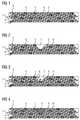
- FIGS. 1 to 4 show how the corona protection according to the invention in the electrical machine heals itself.
- the electrical machine has an electrical conductor, a main insulation, which surrounds the electrical conductor, and the corona shield 1 on.
- the corona shield 1 has a radial outer side 2 and a radial inner side 3.
- the corona shield 1 is applied to the radial outer side of the main insulation, so that the radial inner side 3 bears against the radial outer side of the main insulation.
- the radial outer side 2 of the corona shield 1 is in contact with a laminated core of the electrical machine and can be damaged by this touch contact, by external influence and / or by partial discharges, whereby, as in FIG. 2 shown, a damaged area 7 is formed.
- the microcapsules 5 burst and the second polymer resin located in their interior flows into the damaged area 7, as illustrated by the arrows 8 in FIG.
- the damaged area 7 is filled and annealed, as indicated by reference 9 in FIG. 4 is shown.
Landscapes
- Chemical & Material Sciences (AREA)
- Engineering & Computer Science (AREA)
- Organic Chemistry (AREA)
- Life Sciences & Earth Sciences (AREA)
- Materials Engineering (AREA)
- Wood Science & Technology (AREA)
- Power Engineering (AREA)
- Manufacturing & Machinery (AREA)
- Physics & Mathematics (AREA)
- Dispersion Chemistry (AREA)
- Spectroscopy & Molecular Physics (AREA)
- Organic Insulating Materials (AREA)
- Shielding Devices Or Components To Electric Or Magnetic Fields (AREA)
- Paints Or Removers (AREA)
Priority Applications (4)
| Application Number | Priority Date | Filing Date | Title |
|---|---|---|---|
| EP16170822.7A EP3249659A1 (fr) | 2016-05-23 | 2016-05-23 | Dispositif anti-effluves, machine electrique et procede de production de dispositif anti-effluves |
| US16/303,839 US20200321821A1 (en) | 2016-05-23 | 2017-04-21 | Corona shield, electric machine, and method for manufacturing the corona shield |
| EP17720407.0A EP3443567A1 (fr) | 2016-05-23 | 2017-04-21 | Dispositif anti-effluves, machine électrique et procédé de fabrication du dispositif anti-effluves |
| PCT/EP2017/059487 WO2017202550A1 (fr) | 2016-05-23 | 2017-04-21 | Dispositif anti-effluves, machine électrique et procédé de fabrication du dispositif anti-effluves |
Applications Claiming Priority (1)
| Application Number | Priority Date | Filing Date | Title |
|---|---|---|---|
| EP16170822.7A EP3249659A1 (fr) | 2016-05-23 | 2016-05-23 | Dispositif anti-effluves, machine electrique et procede de production de dispositif anti-effluves |
Publications (1)
| Publication Number | Publication Date |
|---|---|
| EP3249659A1 true EP3249659A1 (fr) | 2017-11-29 |
Family
ID=56083942
Family Applications (2)
| Application Number | Title | Priority Date | Filing Date |
|---|---|---|---|
| EP16170822.7A Withdrawn EP3249659A1 (fr) | 2016-05-23 | 2016-05-23 | Dispositif anti-effluves, machine electrique et procede de production de dispositif anti-effluves |
| EP17720407.0A Withdrawn EP3443567A1 (fr) | 2016-05-23 | 2017-04-21 | Dispositif anti-effluves, machine électrique et procédé de fabrication du dispositif anti-effluves |
Family Applications After (1)
| Application Number | Title | Priority Date | Filing Date |
|---|---|---|---|
| EP17720407.0A Withdrawn EP3443567A1 (fr) | 2016-05-23 | 2017-04-21 | Dispositif anti-effluves, machine électrique et procédé de fabrication du dispositif anti-effluves |
Country Status (3)
| Country | Link |
|---|---|
| US (1) | US20200321821A1 (fr) |
| EP (2) | EP3249659A1 (fr) |
| WO (1) | WO2017202550A1 (fr) |
Citations (5)
| Publication number | Priority date | Publication date | Assignee | Title |
|---|---|---|---|---|
| US3446741A (en) * | 1963-11-14 | 1969-05-27 | Minnesota Mining & Mfg | Insulating device,composition,and method |
| EP1168372A1 (fr) * | 2000-06-20 | 2002-01-02 | Abb Research Ltd. | Résine pour isolation électrique |
| US7285306B1 (en) * | 2003-04-18 | 2007-10-23 | United States Of America As Represented By The Administrator Of The National Aeronautics And Space Administration | Process for self-repair of insulation material |
| DE102009039457A1 (de) * | 2009-08-31 | 2011-03-03 | Siemens Aktiengesellschaft | Leitereinrichtung, elektrische Maschine sowie Traktionsmaschine |
| EP2624258A1 (fr) * | 2012-02-06 | 2013-08-07 | Siemens Aktiengesellschaft | Couche isolante auto-curative pour une machine électrique |
-
2016
- 2016-05-23 EP EP16170822.7A patent/EP3249659A1/fr not_active Withdrawn
-
2017
- 2017-04-21 EP EP17720407.0A patent/EP3443567A1/fr not_active Withdrawn
- 2017-04-21 WO PCT/EP2017/059487 patent/WO2017202550A1/fr not_active Ceased
- 2017-04-21 US US16/303,839 patent/US20200321821A1/en not_active Abandoned
Patent Citations (5)
| Publication number | Priority date | Publication date | Assignee | Title |
|---|---|---|---|---|
| US3446741A (en) * | 1963-11-14 | 1969-05-27 | Minnesota Mining & Mfg | Insulating device,composition,and method |
| EP1168372A1 (fr) * | 2000-06-20 | 2002-01-02 | Abb Research Ltd. | Résine pour isolation électrique |
| US7285306B1 (en) * | 2003-04-18 | 2007-10-23 | United States Of America As Represented By The Administrator Of The National Aeronautics And Space Administration | Process for self-repair of insulation material |
| DE102009039457A1 (de) * | 2009-08-31 | 2011-03-03 | Siemens Aktiengesellschaft | Leitereinrichtung, elektrische Maschine sowie Traktionsmaschine |
| EP2624258A1 (fr) * | 2012-02-06 | 2013-08-07 | Siemens Aktiengesellschaft | Couche isolante auto-curative pour une machine électrique |
Non-Patent Citations (1)
| Title |
|---|
| YUAN YAN CHAO ET AL: "Self-Healing Polymeric Materials Using Epoxy/Mercaptan as the Healant", MACROMOLECULES, AMERICAN CHEMICAL SOCIETY, US, vol. 41, 27 June 2008 (2008-06-27), pages 5197 - 5202, XP002530957, ISSN: 0024-9297, [retrieved on 20080627], DOI: 10.1021/MA800028D * |
Also Published As
| Publication number | Publication date |
|---|---|
| EP3443567A1 (fr) | 2019-02-20 |
| US20200321821A1 (en) | 2020-10-08 |
| WO2017202550A1 (fr) | 2017-11-30 |
Similar Documents
| Publication | Publication Date | Title |
|---|---|---|
| AT521301B1 (de) | Stator mit Isolationsschicht | |
| EP1573882B1 (fr) | Bobines pour moteurs electriques realisees selon la technique des conducteurs multibrins | |
| DE102011079489A1 (de) | Verfahren zum Herstellen eines Bandes für ein elektrisches Isolationssystem | |
| DE112019006760B4 (de) | Isolierter elektrischer draht und verkabelung | |
| DE602004001781T2 (de) | Elektrische leitung beschichtet mit einer haftenden schicht und herstellungsprozess davon | |
| EP2624258A1 (fr) | Couche isolante auto-curative pour une machine électrique | |
| DE102012207535A1 (de) | Isolierband-Material, Verfahren zur Herstellung und Verwendung dazu | |
| DE102011075425A1 (de) | Verfahren zum Herstellen eines elektrischen Isolationssystems für eine elektrische Maschine | |
| WO1997043818A1 (fr) | Corps support pour bobinage electrique et procede de fabrication d'un dispositif anti-effluves | |
| DE102016202391A1 (de) | Kompakter Trockentransformator mit einer elektrischen Wicklung und Verfahren zur Herstellung einer elektrischen Wicklung | |
| EP4272300A1 (fr) | Système d'isolation d'encoche pour machine électrique tournante, procédé de fabrication d'un système d'isolation d'encoche | |
| DE102012208226A1 (de) | Endenglimmschutzband und Verfahren zum Herstellen des Endenglimmschutzbandes | |
| DE102012205650A1 (de) | Isolierstoff für rotierende Maschinen | |
| EP3776813A1 (fr) | Système d'isolation électrique d'un moteur électrique et procédé de fabrication correspondant | |
| EP0657061B1 (fr) | Ruban isolant pour enroulement de machines electriques---------- | |
| EP3249659A1 (fr) | Dispositif anti-effluves, machine electrique et procede de production de dispositif anti-effluves | |
| EP3240150A1 (fr) | Machine electrique et procede de demontage et de production d'une machine electrique | |
| EP2831173A2 (fr) | Corps isolant de l'électricité pour une machine tournante à haute tension et procédé de fabrication du corps isolant de l'électricité | |
| EP1813419A1 (fr) | Materiau isolant | |
| EP4307322A1 (fr) | Fil rond isolé par un vernis, procédé de fabrication et utilisation correspondante | |
| EP3607564B1 (fr) | Bande d'isolation électrique, machine électrique haute tension et procédé de fabrication d'une bande d'isolation électrique et machine électrique haute tension | |
| DE69305681T2 (de) | Isolierungsverfahren eines elektrischen Leiters und isolierter elektrischer Daht hergestellt nach diesem Verfahren | |
| EP2521247A1 (fr) | Système de protection anti-rougoiement électrique pour une machine haute tension | |
| DE10345312A1 (de) | Härtbares Reaktionsharzsystem | |
| DE102024107407A1 (de) | Lagerring und Verfahren zu dessen Herstellung, sowie Wälzlager oder Gleitlager mit mindestens einem solchen Lagerring |
Legal Events
| Date | Code | Title | Description |
|---|---|---|---|
| PUAI | Public reference made under article 153(3) epc to a published international application that has entered the european phase |
Free format text: ORIGINAL CODE: 0009012 |
|
| AK | Designated contracting states |
Kind code of ref document: A1 Designated state(s): AL AT BE BG CH CY CZ DE DK EE ES FI FR GB GR HR HU IE IS IT LI LT LU LV MC MK MT NL NO PL PT RO RS SE SI SK SM TR |
|
| AX | Request for extension of the european patent |
Extension state: BA ME |
|
| STAA | Information on the status of an ep patent application or granted ep patent |
Free format text: STATUS: THE APPLICATION IS DEEMED TO BE WITHDRAWN |
|
| 18D | Application deemed to be withdrawn |
Effective date: 20180530 |