EP3249662B1 - Moteur de pompe électrique - Google Patents
Moteur de pompe électrique Download PDFInfo
- Publication number
- EP3249662B1 EP3249662B1 EP17165112.8A EP17165112A EP3249662B1 EP 3249662 B1 EP3249662 B1 EP 3249662B1 EP 17165112 A EP17165112 A EP 17165112A EP 3249662 B1 EP3249662 B1 EP 3249662B1
- Authority
- EP
- European Patent Office
- Prior art keywords
- connection
- wire
- pump motor
- connecting element
- electric pump
- Prior art date
- Legal status (The legal status is an assumption and is not a legal conclusion. Google has not performed a legal analysis and makes no representation as to the accuracy of the status listed.)
- Active
Links
Images

Classifications
-
- H—ELECTRICITY
- H01—ELECTRIC ELEMENTS
- H01R—ELECTRICALLY-CONDUCTIVE CONNECTIONS; STRUCTURAL ASSOCIATIONS OF A PLURALITY OF MUTUALLY-INSULATED ELECTRICAL CONNECTING ELEMENTS; COUPLING DEVICES; CURRENT COLLECTORS
- H01R4/00—Electrically-conductive connections between two or more conductive members in direct contact, i.e. touching one another; Means for effecting or maintaining such contact; Electrically-conductive connections having two or more spaced connecting locations for conductors and using contact members penetrating insulation
- H01R4/70—Insulation of connections
- H01R4/72—Insulation of connections using a heat shrinking insulating sleeve
- H01R4/723—Making a soldered electrical connection simultaneously with the heat shrinking
-
- H—ELECTRICITY
- H01—ELECTRIC ELEMENTS
- H01B—CABLES; CONDUCTORS; INSULATORS; SELECTION OF MATERIALS FOR THEIR CONDUCTIVE, INSULATING OR DIELECTRIC PROPERTIES
- H01B1/00—Conductors or conductive bodies characterised by the conductive materials; Selection of materials as conductors
- H01B1/02—Conductors or conductive bodies characterised by the conductive materials; Selection of materials as conductors mainly consisting of metals or alloys
- H01B1/023—Alloys based on aluminium
-
- H—ELECTRICITY
- H01—ELECTRIC ELEMENTS
- H01B—CABLES; CONDUCTORS; INSULATORS; SELECTION OF MATERIALS FOR THEIR CONDUCTIVE, INSULATING OR DIELECTRIC PROPERTIES
- H01B3/00—Insulators or insulating bodies characterised by the insulating materials; Selection of materials for their insulating or dielectric properties
- H01B3/18—Insulators or insulating bodies characterised by the insulating materials; Selection of materials for their insulating or dielectric properties mainly consisting of organic substances
- H01B3/30—Insulators or insulating bodies characterised by the insulating materials; Selection of materials for their insulating or dielectric properties mainly consisting of organic substances plastics; resins; waxes
- H01B3/303—Macromolecular compounds obtained by reactions forming a linkage containing nitrogen with or without oxygen or carbon in the main chain of the macromolecule, not provided for in groups H01B3/38 or H01B3/302
- H01B3/305—Polyamides or polyesteramides
-
- H—ELECTRICITY
- H01—ELECTRIC ELEMENTS
- H01F—MAGNETS; INDUCTANCES; TRANSFORMERS; SELECTION OF MATERIALS FOR THEIR MAGNETIC PROPERTIES
- H01F27/00—Details of transformers or inductances, in general
- H01F27/28—Coils; Windings; Conductive connections
- H01F27/29—Terminals; Tapping arrangements for signal inductances
-
- H—ELECTRICITY
- H01—ELECTRIC ELEMENTS
- H01F—MAGNETS; INDUCTANCES; TRANSFORMERS; SELECTION OF MATERIALS FOR THEIR MAGNETIC PROPERTIES
- H01F41/00—Apparatus or processes specially adapted for manufacturing or assembling magnets, inductances or transformers; Apparatus or processes specially adapted for manufacturing materials characterised by their magnetic properties
- H01F41/02—Apparatus or processes specially adapted for manufacturing or assembling magnets, inductances or transformers; Apparatus or processes specially adapted for manufacturing materials characterised by their magnetic properties for manufacturing cores, coils, or magnets
- H01F41/04—Apparatus or processes specially adapted for manufacturing or assembling magnets, inductances or transformers; Apparatus or processes specially adapted for manufacturing materials characterised by their magnetic properties for manufacturing cores, coils, or magnets for manufacturing coils
- H01F41/10—Connecting leads to windings
-
- H—ELECTRICITY
- H01—ELECTRIC ELEMENTS
- H01F—MAGNETS; INDUCTANCES; TRANSFORMERS; SELECTION OF MATERIALS FOR THEIR MAGNETIC PROPERTIES
- H01F5/00—Coils
- H01F5/04—Arrangements of electric connections to coils, e.g. leads
-
- H—ELECTRICITY
- H01—ELECTRIC ELEMENTS
- H01R—ELECTRICALLY-CONDUCTIVE CONNECTIONS; STRUCTURAL ASSOCIATIONS OF A PLURALITY OF MUTUALLY-INSULATED ELECTRICAL CONNECTING ELEMENTS; COUPLING DEVICES; CURRENT COLLECTORS
- H01R4/00—Electrically-conductive connections between two or more conductive members in direct contact, i.e. touching one another; Means for effecting or maintaining such contact; Electrically-conductive connections having two or more spaced connecting locations for conductors and using contact members penetrating insulation
- H01R4/58—Electrically-conductive connections between two or more conductive members in direct contact, i.e. touching one another; Means for effecting or maintaining such contact; Electrically-conductive connections having two or more spaced connecting locations for conductors and using contact members penetrating insulation characterised by the form or material of the contacting members
- H01R4/62—Connections between conductors of different materials; Connections between or with aluminium or steel-core aluminium conductors
- H01R4/625—Soldered or welded connections
-
- H—ELECTRICITY
- H01—ELECTRIC ELEMENTS
- H01R—ELECTRICALLY-CONDUCTIVE CONNECTIONS; STRUCTURAL ASSOCIATIONS OF A PLURALITY OF MUTUALLY-INSULATED ELECTRICAL CONNECTING ELEMENTS; COUPLING DEVICES; CURRENT COLLECTORS
- H01R4/00—Electrically-conductive connections between two or more conductive members in direct contact, i.e. touching one another; Means for effecting or maintaining such contact; Electrically-conductive connections having two or more spaced connecting locations for conductors and using contact members penetrating insulation
- H01R4/70—Insulation of connections
- H01R4/72—Insulation of connections using a heat shrinking insulating sleeve
-
- H—ELECTRICITY
- H01—ELECTRIC ELEMENTS
- H01R—ELECTRICALLY-CONDUCTIVE CONNECTIONS; STRUCTURAL ASSOCIATIONS OF A PLURALITY OF MUTUALLY-INSULATED ELECTRICAL CONNECTING ELEMENTS; COUPLING DEVICES; CURRENT COLLECTORS
- H01R43/00—Apparatus or processes specially adapted for manufacturing, assembling, maintaining, or repairing of line connectors or current collectors or for joining electric conductors
- H01R43/02—Apparatus or processes specially adapted for manufacturing, assembling, maintaining, or repairing of line connectors or current collectors or for joining electric conductors for soldered or welded connections
-
- H—ELECTRICITY
- H01—ELECTRIC ELEMENTS
- H01R—ELECTRICALLY-CONDUCTIVE CONNECTIONS; STRUCTURAL ASSOCIATIONS OF A PLURALITY OF MUTUALLY-INSULATED ELECTRICAL CONNECTING ELEMENTS; COUPLING DEVICES; CURRENT COLLECTORS
- H01R43/00—Apparatus or processes specially adapted for manufacturing, assembling, maintaining, or repairing of line connectors or current collectors or for joining electric conductors
- H01R43/02—Apparatus or processes specially adapted for manufacturing, assembling, maintaining, or repairing of line connectors or current collectors or for joining electric conductors for soldered or welded connections
- H01R43/0207—Ultrasonic-, H.F.-, cold- or impact welding
Definitions
- the invention relates to an electric pump motor, which has a connection arrangement with a wire and a connection body.
- connection body Various contacting methods are known from the prior art in order to connect a wire, for example an aluminum wire used as a winding for an electric motor, to the connection body and to protect the connection point formed between the wire and the connection body.
- the connection is made in an industrial environment, for example by soldering or welding or ultrasonic bonding. It is also known to use an insulation displacement technique for connecting the wire to the connection body.
- connection point between the wire and the connector body forms a weak point that needs to be protected.
- it is known to encapsulate it with thermoplastic or thermoset materials, to cast it with epoxy or a similar material, or to apply a layer of lacquer.
- thermoplastic or thermoset materials to cast it with epoxy or a similar material, or to apply a layer of lacquer.
- CN 204 741 344 U known to protect the grease or other lubricant To bring the connection point onto this.
- the materials used here are hydrocarbons thickened with silicon oxide, polydimethylsiloxane or a classic silicone.
- the US 2015/111442 A1 describes a welding process for a multi-core cable, which is applied to a connector body and then sheathed. Such arrangements for multi-core cables are also from the JP 2015 118826 A and the JP 2015 026429 A known.
- CN 203 953 323 U discloses an electromagnetic jig with a connection arrangement with a contact pin.
- the object of the invention is to provide an electric pump motor in which the connection point formed between the wire and the connection body can be produced particularly economically and is advantageously protected against damaging environmental influences.
- the invention has the features of claim 1.
- the wire is firmly bonded to the connector body. After the connection has been made, the shrink tube with the inner adhesive is placed over the connection point.
- the shrink tube is heated after the covering has been produced.
- part of the thermoplastic inner adhesive can pass through a gap which is formed between the connection body and the shrink tube.
- connection point is excellently electrically insulated by the inner adhesive and the shrink tube.
- connection point and the part of the wire covered by the sheath are protected against corrosion.
- the shrink tube with the inner adhesive prevents contact with oxygen or water.
- the shrink tube is also resistant to aging.
- the internal adhesive and the material properties of the shrink tube prevent tension cracks or minimize the tendency to become brittle.
- the connection point is resistant to aggressive media such as oil, acid, alkali or salts.
- good temperature resistance is guaranteed in the normal operating temperature ranges of an aluminum winding for coil formers.
- there is no risk of the shrink tube melting since it no longer flows at temperatures above the crystalline melting point, but becomes elastic like an elastomer.
- the good insulation also means that the wire, if it is designed as enamelled aluminum wire, no longer requires an additional insulation layer or additional insulation protection.
- the shrinked hose, with which the connection point is encased promotes an even and permanent application of force to the connection points. It represents an additional mechanical security and ensures a permanently good connection.
- the investment costs in plant technology are low economically.
- the connection process is suitable for large series and easy to control. The cycle times are low.
- the wire is bonded to the connection body.
- a bond machine is used to manufacture the bond site.
- the wire is pressed against the connection body by a tool of the automatic bonding machine and excited by the tool to ultrasonic vibrations.
- connection points are formed.
- the at least two and preferably all connection points are produced on the same side of the connection body.
- the bonding of wire and connection body can advantageously produce a material connection with a low electrical contact resistance.
- the reliability of the electrical connection improves when two or more connection points between the wire and the connector body.
- the two or more points are produced in an economically advantageous manner on a common side of the connection body, since repositioning of the connection body and / or the wire can be avoided when the connection is made.
- connection body can provide guide means for the wire.
- guide recesses for the wire can be provided on the connection body.
- the geometry of the area to be insulated i.e. the geometry of the connector body and the connection point, must be taken into account and the quality requirements for the product must be taken into account.
- the continuous operating temperature of the shrink tube and the winding formed by the wire must be taken into account.
- Another important parameter is the volume to be protected, which the inner adhesive must seal. This must also be taken into account when selecting the shrink tube.
- the use of the shrink tube with the inner adhesive is very advantageous in terms of process technology, since the inner adhesive and the shrink tube can be applied in a common process step.
- a thermoplastic inner adhesive and in particular an inner adhesive based on polyamide can be used as the inner adhesive.
- an ethylene-vinyl acetate copolymer (elastomer adhesive) can be used as an internal adhesive.
- a melting point of the same in the range of approximately 135 ° C. can be provided.
- connection arrangement comprises a connection body and a wire which is fixed to the connection body at a connection point in at least one connection point, as well as a sheath for the connection point.
- the sheath has a thermoplastic inner adhesive encompassing the wire and the connection body in the area of the connection point and a shrink tube likewise encompassing the wire and the connection body in the area of the connection point.
- a flat plug of a coil former serves as a connection body.
- the inner adhesive is preferably designed as an elastomer adhesive or thermoplastic inner adhesive and is provided between the connection body and the shrink tube.
- the wire and the connecting body are integrally connected to one another at at least two points.
- the two points are provided on a common side of the connection body and preferably on a common flat side of the flat plug serving as the connection body.
- pump motors according to the invention have a named connection arrangement in order to firmly attach a wire of the windings to a connection body of the motor.
- the integral connection between the wire and the connection body is produced according to the invention by ultrasonic wire bonding.
- connection arrangement for an electric pump motor according to the invention, which provides two connection bodies 4, which are made in the manner of a flat plug from an electrically conductive material.
- a wire 1 is also provided, which on the one hand forms a winding 10 and on the other hand is fixed to the connection bodies 4 in two points 2, 3.
- the connection points 2, 3 designed for the cohesive, electrically conductive connection of the wire 1 to the connection body 4 are produced in the present exemplary embodiment of the invention by means of an ultrasonic wire bonding machine. It is the case here that the wire 1 is pressed against the connection body 4 by a tool of the automatic bonding machine and that the tool is excited to produce ultrasonic vibrations. Due to the ultrasonic vibrations, the wire 1 is connected to the connector body 4 in a cohesive manner.
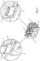
- a determination of the wire 1 on the connector body 4 according to Fig. 1 is achieved in particular before the bond connection is established by winding the wire 1 around the connection body 4 and positioning it in the region of two guide recesses 9 which are formed on two opposite narrow sides of the flat plug 4.
- the connection points 2, 3 are provided on between the guide recesses 9 on the same flat side of the connection body 4.
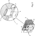
- a shrink tube 6 with a thermoplastic inner adhesive 7 is applied in the area of the connection point comprising points 2, 3, which electrically insulates and encapsulates the connection point (cf. Fig. 2 ).
- the shrink tube 6 encompasses the connecting body 4 with the wire 1 and the thermoplastic inner adhesive 7.
- the shrink tube 6 is heated after the covering has been produced. In the area of a gap formed between the connector body 4 on the one hand and the shrink tube 6 on the other hand, part of the thermoplastic inner adhesive 7 emerges (not shown).
- connection bodies 4 are used for contacting the windings 10 carried by a coil body 5.
- a further connection body 8 is provided, which is not electrically contacted and remains inoperative in the embodiment shown.
- connection bodies 4 are modified in such a way that the connection bodies 4 designed as flat plugs are provided in the same orientation, whereas in the first exemplary embodiment of the invention, the connection bodies 4 have an orientation that is rotated by 90 ° to one another.
- An elastomer adhesive can be provided as the internal adhesive, and in particular an internal adhesive based on ethylene-vinyl acetate (ethylene-vinyl acetate copolymer).
- the invention is not limited to the embodiment variant shown here.
- the connector body 4 can have a different geometry.
Landscapes
- Engineering & Computer Science (AREA)
- Power Engineering (AREA)
- Manufacturing & Machinery (AREA)
- Physics & Mathematics (AREA)
- Spectroscopy & Molecular Physics (AREA)
- Chemical & Material Sciences (AREA)
- Chemical Kinetics & Catalysis (AREA)
- Connections Effected By Soldering, Adhesion, Or Permanent Deformation (AREA)
Claims (7)
- Moteur électrique de pompe comprenant un enroulement (10) qui est prévu sur une corps de bobine (5) du moteur de pompe et comprenant un corps de raccordement (4) pour le contact électrique de l'enroulement (10), dans lequel un fil d'aluminium (1) de l'enroulement (10) est relié au corps de raccordement (4) par un agencement de liaison, dans lequel l'agencement de liaison comprend le corps de raccordement (4) et le fil (1) fixé au corps de raccordement (4) à un emplacement de liaison en au moins un point (2, 3) par liaison de matière ainsi qu'une enveloppe pour l'emplacement de liaison réalisée après la fixation par liaison de matière, caractérisé en ce que l'enveloppe prévoit une gaine thermorétractable (6) avec un adhésif intérieur (7) qui entoure le fil (1) et le corps de raccordement (4) dans la zone de l'emplacement de liaison et que l'assemblage par liaison de matière est réalisé en ledit au moins un point (2, 3) au moyen d'un automate de liaison, le fil (1) ayant, lors de la réalisation de la liaison, été pressé contre le corps de raccordement (4) par un outil de l'automate de liaison et amené par l'outil à entrer en vibrations ultrasoniques.
- Moteur électrique de pompe selon la revendication 1, caractérisé en ce que le fil d'aluminium (1) est réalisé sous la forme d'un fil d'aluminium émaillé.
- Moteur électrique de pompe selon la revendication 1 ou 2, caractérisé en ce que le corps de raccordement (4) est formé par une fiche plate du corps de bobine (5).
- Moteur électrique de pompe selon l'une des revendications 1 à 3, caractérisé en ce que l'adhésif intérieur (7) est prévu entre le corps de raccordement (4) et la gaine thermorétractable (6).
- Moteur électrique de pompe selon l'une des revendications 1 à 4, caractérisé en ce que le fil (1) est relié au corps de raccordement (4) en au moins deux points (2, 3), les points (2, 3) étant prévus sur un côté commun du corps de raccordement (4) et, en particulier pour un moteur de pompe selon la revendication 3, sur un même côté plat de la fiche plate.
- Moteur électrique de pompe selon l'une des revendications 1 à 5, caractérisé en ce qu'un adhésif intérieur thermoplastique et/ou un adhésif élastomère sont prévus comme adhésif intérieur (7).
- Moteur électrique de pompe selon l'une des revendications 1 à 6, caractérisé en ce qu'au moins deux et de préférence tous les points (2, 3) de l'emplacement de liaison sont réalisés sur un même côté plat du corps de raccordement (4).
Priority Applications (1)
| Application Number | Priority Date | Filing Date | Title |
|---|---|---|---|
| PL17165112T PL3249662T3 (pl) | 2016-05-27 | 2017-04-05 | Silnik elektryczny do napędu pompy |
Applications Claiming Priority (2)
| Application Number | Priority Date | Filing Date | Title |
|---|---|---|---|
| DE102016109797 | 2016-05-27 | ||
| DE102017106769 | 2017-03-29 |
Publications (2)
| Publication Number | Publication Date |
|---|---|
| EP3249662A1 EP3249662A1 (fr) | 2017-11-29 |
| EP3249662B1 true EP3249662B1 (fr) | 2020-05-13 |
Family
ID=58548984
Family Applications (1)
| Application Number | Title | Priority Date | Filing Date |
|---|---|---|---|
| EP17165112.8A Active EP3249662B1 (fr) | 2016-05-27 | 2017-04-05 | Moteur de pompe électrique |
Country Status (3)
| Country | Link |
|---|---|
| US (1) | US10439301B2 (fr) |
| EP (1) | EP3249662B1 (fr) |
| PL (1) | PL3249662T3 (fr) |
Families Citing this family (1)
| Publication number | Priority date | Publication date | Assignee | Title |
|---|---|---|---|---|
| DE102020122404A1 (de) * | 2020-08-27 | 2022-03-03 | Vem Sachsenwerk Gmbh | Klimafeste Magnetspule |
Family Cites Families (13)
| Publication number | Priority date | Publication date | Assignee | Title |
|---|---|---|---|---|
| DE19808069A1 (de) * | 1998-02-26 | 1999-09-02 | Bosch Gmbh Robert | Verfahren zum Fixieren einer Rotorwicklung |
| DE19852929C1 (de) * | 1998-11-17 | 2000-03-30 | Hanning Elektro Werke | Thermoschalter-Anordnung für elektromagnetische Spulen |
| WO2000057896A1 (fr) * | 1999-03-26 | 2000-10-05 | The University Of Texas System | Modulateurs de polysaccharides et leurs utilisations |
| GB2354639B (en) * | 1999-09-17 | 2003-09-24 | Honda Lock Mfg Co Ltd | Electromagnetic coil device |
| JP2008113539A (ja) * | 2006-10-03 | 2008-05-15 | Denso Corp | 交流回転電機 |
| DE102008009620A1 (de) * | 2008-02-18 | 2009-08-20 | Lapp Engineering & Co. | Steckverbinderelement mit Abdichtung im Kabelanschlußbereich |
| JP5452570B2 (ja) * | 2011-11-09 | 2014-03-26 | 三菱電機株式会社 | 回転電機およびそのステータコイルの結線ユニットの製造方法 |
| JP2013246886A (ja) * | 2012-05-23 | 2013-12-09 | Auto Network Gijutsu Kenkyusho:Kk | 端子付き電線およびその製造方法、ならびに治具 |
| JP6127801B2 (ja) * | 2013-07-24 | 2017-05-17 | 株式会社オートネットワーク技術研究所 | ワイヤハーネスの製造方法 |
| JP5657085B1 (ja) * | 2013-11-08 | 2015-01-21 | 三菱電機株式会社 | 回転電機および回転電機用ステータの製造方法 |
| JP6028934B2 (ja) * | 2013-12-19 | 2016-11-24 | 住友電装株式会社 | 端子付電線 |
| CN203953323U (zh) * | 2014-07-02 | 2014-11-26 | 宁波捷尔天电气有限公司 | 一种电磁吸盘 |
| CN204741344U (zh) | 2015-04-17 | 2015-11-04 | 阿思科尔控股责任有限公司(独资) | 排水泵 |
-
2017
- 2017-04-05 PL PL17165112T patent/PL3249662T3/pl unknown
- 2017-04-05 EP EP17165112.8A patent/EP3249662B1/fr active Active
- 2017-05-15 US US15/594,805 patent/US10439301B2/en active Active
Non-Patent Citations (1)
| Title |
|---|
| None * |
Also Published As
| Publication number | Publication date |
|---|---|
| US10439301B2 (en) | 2019-10-08 |
| PL3249662T3 (pl) | 2020-11-16 |
| US20170346199A1 (en) | 2017-11-30 |
| EP3249662A1 (fr) | 2017-11-29 |
Similar Documents
| Publication | Publication Date | Title |
|---|---|---|
| DE112012003786T5 (de) | Verbindungsklemme | |
| DE102016102948A1 (de) | Verfahren und Vorrichtung zur Abdichtung von Kontaktstellen an elektrischen Leitungsverbindungen | |
| DE102014109604B4 (de) | Kontaktierung eines Litzenleiters | |
| EP3155701B1 (fr) | Structure à tracé conducteur à surmoulage en matière plastique et procédé de production de la structure à tracé conducteur à surmoulage en matière plastique | |
| DE10054714B4 (de) | Verfahren zum Abdichten eines Kabels oder Kabelsatzes an/in einem Kabeldurchführungselement sowie ein Kabeldurchführungselement | |
| EP2245705B1 (fr) | Élément connecteur à fiche, à effet d'étanchéité dans la région de raccordement du câble | |
| DE102013005399A1 (de) | Motorstruktur mit Verbinder oder Anschlussblock, an den ein leitfähigabgedichteter Anschluss gelötet ist" | |
| EP2731203B1 (fr) | Procédé de recouvrement imperméable d'un emplacement de liaison entre un conducteur électrique et un élément de contact | |
| DE102011011409A1 (de) | Anschlussteil und Verbindung für elektrische Anlagen | |
| EP3249662A1 (fr) | Procédé de mise en contact et agencement de connexion | |
| DE102011016556B4 (de) | Elektrische Kontakteinrichtung | |
| DE102015117020B4 (de) | Verfahren zum Herstellen einer Leitungsabdichtung eines Leitungsstrangs und Verfahren zur Herstellung einer gedichteten Leitungsverbindung | |
| DE102004057750B4 (de) | Verfahren zur Herstellung eines Kommutators sowie Kommutator | |
| DE102008055124A1 (de) | Dichtung für wenigstens eine elektrische Leitung | |
| EP3342008B1 (fr) | Procédé de fabrication d'une connexion enfichable, procédé de renforcement d'une connexion enfichable et dispositif associé | |
| DE102006025661B4 (de) | Kontaktklemme zum Anschließen eines Litzenleiters an einen relativ dünnen Anschlussstift | |
| WO2012080381A1 (fr) | Piézoactionneur | |
| EP3466224B1 (fr) | Ensemble de grilles estampées pour module de commande de transmission comportant des grilles estampées en cu et al reliées par une liaison filaire soudée encapsulée | |
| EP3133696A1 (fr) | Dispositif de mise en contact et procede de fabrication | |
| DE102015201711A1 (de) | Verfahren zum Kompaktieren von Einzeldrähten | |
| WO2013098047A1 (fr) | Dispositif de raccordement de machines électriques | |
| DE102011011431B4 (de) | Elektrisches Heizelement mit einem Verbindungselement und Verfahren zur Herstellung eines elektrischen Heizelements mit einem Verbindungselement | |
| DE102016221147A1 (de) | Verbindungsanordnung zwischen einem Kabelschuh und einer elektrischen Leitung, Verfahren zur Herstellung einer solchen sowie Elektromaschine | |
| EP3206268B1 (fr) | Procede d'etancheification impermeable d'un element de connection electrique | |
| DE102010032438A1 (de) | Verfahren zum Befestigen eines Thermoelementes an einem metallischen Bauteil |
Legal Events
| Date | Code | Title | Description |
|---|---|---|---|
| PUAI | Public reference made under article 153(3) epc to a published international application that has entered the european phase |
Free format text: ORIGINAL CODE: 0009012 |
|
| STAA | Information on the status of an ep patent application or granted ep patent |
Free format text: STATUS: THE APPLICATION HAS BEEN PUBLISHED |
|
| AK | Designated contracting states |
Kind code of ref document: A1 Designated state(s): AL AT BE BG CH CY CZ DE DK EE ES FI FR GB GR HR HU IE IS IT LI LT LU LV MC MK MT NL NO PL PT RO RS SE SI SK SM TR |
|
| AX | Request for extension of the european patent |
Extension state: BA ME |
|
| STAA | Information on the status of an ep patent application or granted ep patent |
Free format text: STATUS: REQUEST FOR EXAMINATION WAS MADE |
|
| 17P | Request for examination filed |
Effective date: 20180523 |
|
| RBV | Designated contracting states (corrected) |
Designated state(s): AL AT BE BG CH CY CZ DE DK EE ES FI FR GB GR HR HU IE IS IT LI LT LU LV MC MK MT NL NO PL PT RO RS SE SI SK SM TR |
|
| GRAP | Despatch of communication of intention to grant a patent |
Free format text: ORIGINAL CODE: EPIDOSNIGR1 |
|
| STAA | Information on the status of an ep patent application or granted ep patent |
Free format text: STATUS: GRANT OF PATENT IS INTENDED |
|
| INTG | Intention to grant announced |
Effective date: 20200210 |
|
| GRAS | Grant fee paid |
Free format text: ORIGINAL CODE: EPIDOSNIGR3 |
|
| GRAA | (expected) grant |
Free format text: ORIGINAL CODE: 0009210 |
|
| STAA | Information on the status of an ep patent application or granted ep patent |
Free format text: STATUS: THE PATENT HAS BEEN GRANTED |
|
| AK | Designated contracting states |
Kind code of ref document: B1 Designated state(s): AL AT BE BG CH CY CZ DE DK EE ES FI FR GB GR HR HU IE IS IT LI LT LU LV MC MK MT NL NO PL PT RO RS SE SI SK SM TR |
|
| REG | Reference to a national code |
Ref country code: GB Ref legal event code: FG4D Free format text: NOT ENGLISH |
|
| REG | Reference to a national code |
Ref country code: CH Ref legal event code: EP |
|
| REG | Reference to a national code |
Ref country code: DE Ref legal event code: R096 Ref document number: 502017005205 Country of ref document: DE |
|
| REG | Reference to a national code |
Ref country code: AT Ref legal event code: REF Ref document number: 1271306 Country of ref document: AT Kind code of ref document: T Effective date: 20200615 |
|
| REG | Reference to a national code |
Ref country code: LT Ref legal event code: MG4D |
|
| REG | Reference to a national code |
Ref country code: NL Ref legal event code: MP Effective date: 20200513 |
|
| PG25 | Lapsed in a contracting state [announced via postgrant information from national office to epo] |
Ref country code: IS Free format text: LAPSE BECAUSE OF FAILURE TO SUBMIT A TRANSLATION OF THE DESCRIPTION OR TO PAY THE FEE WITHIN THE PRESCRIBED TIME-LIMIT Effective date: 20200913 Ref country code: PT Free format text: LAPSE BECAUSE OF FAILURE TO SUBMIT A TRANSLATION OF THE DESCRIPTION OR TO PAY THE FEE WITHIN THE PRESCRIBED TIME-LIMIT Effective date: 20200914 Ref country code: SE Free format text: LAPSE BECAUSE OF FAILURE TO SUBMIT A TRANSLATION OF THE DESCRIPTION OR TO PAY THE FEE WITHIN THE PRESCRIBED TIME-LIMIT Effective date: 20200513 Ref country code: FI Free format text: LAPSE BECAUSE OF FAILURE TO SUBMIT A TRANSLATION OF THE DESCRIPTION OR TO PAY THE FEE WITHIN THE PRESCRIBED TIME-LIMIT Effective date: 20200513 Ref country code: NO Free format text: LAPSE BECAUSE OF FAILURE TO SUBMIT A TRANSLATION OF THE DESCRIPTION OR TO PAY THE FEE WITHIN THE PRESCRIBED TIME-LIMIT Effective date: 20200813 Ref country code: GR Free format text: LAPSE BECAUSE OF FAILURE TO SUBMIT A TRANSLATION OF THE DESCRIPTION OR TO PAY THE FEE WITHIN THE PRESCRIBED TIME-LIMIT Effective date: 20200814 Ref country code: LT Free format text: LAPSE BECAUSE OF FAILURE TO SUBMIT A TRANSLATION OF THE DESCRIPTION OR TO PAY THE FEE WITHIN THE PRESCRIBED TIME-LIMIT Effective date: 20200513 |
|
| PG25 | Lapsed in a contracting state [announced via postgrant information from national office to epo] |
Ref country code: LV Free format text: LAPSE BECAUSE OF FAILURE TO SUBMIT A TRANSLATION OF THE DESCRIPTION OR TO PAY THE FEE WITHIN THE PRESCRIBED TIME-LIMIT Effective date: 20200513 Ref country code: BG Free format text: LAPSE BECAUSE OF FAILURE TO SUBMIT A TRANSLATION OF THE DESCRIPTION OR TO PAY THE FEE WITHIN THE PRESCRIBED TIME-LIMIT Effective date: 20200813 Ref country code: RS Free format text: LAPSE BECAUSE OF FAILURE TO SUBMIT A TRANSLATION OF THE DESCRIPTION OR TO PAY THE FEE WITHIN THE PRESCRIBED TIME-LIMIT Effective date: 20200513 Ref country code: HR Free format text: LAPSE BECAUSE OF FAILURE TO SUBMIT A TRANSLATION OF THE DESCRIPTION OR TO PAY THE FEE WITHIN THE PRESCRIBED TIME-LIMIT Effective date: 20200513 |
|
| PG25 | Lapsed in a contracting state [announced via postgrant information from national office to epo] |
Ref country code: NL Free format text: LAPSE BECAUSE OF FAILURE TO SUBMIT A TRANSLATION OF THE DESCRIPTION OR TO PAY THE FEE WITHIN THE PRESCRIBED TIME-LIMIT Effective date: 20200513 Ref country code: AL Free format text: LAPSE BECAUSE OF FAILURE TO SUBMIT A TRANSLATION OF THE DESCRIPTION OR TO PAY THE FEE WITHIN THE PRESCRIBED TIME-LIMIT Effective date: 20200513 |
|
| PG25 | Lapsed in a contracting state [announced via postgrant information from national office to epo] |
Ref country code: SM Free format text: LAPSE BECAUSE OF FAILURE TO SUBMIT A TRANSLATION OF THE DESCRIPTION OR TO PAY THE FEE WITHIN THE PRESCRIBED TIME-LIMIT Effective date: 20200513 Ref country code: EE Free format text: LAPSE BECAUSE OF FAILURE TO SUBMIT A TRANSLATION OF THE DESCRIPTION OR TO PAY THE FEE WITHIN THE PRESCRIBED TIME-LIMIT Effective date: 20200513 Ref country code: DK Free format text: LAPSE BECAUSE OF FAILURE TO SUBMIT A TRANSLATION OF THE DESCRIPTION OR TO PAY THE FEE WITHIN THE PRESCRIBED TIME-LIMIT Effective date: 20200513 Ref country code: CZ Free format text: LAPSE BECAUSE OF FAILURE TO SUBMIT A TRANSLATION OF THE DESCRIPTION OR TO PAY THE FEE WITHIN THE PRESCRIBED TIME-LIMIT Effective date: 20200513 Ref country code: RO Free format text: LAPSE BECAUSE OF FAILURE TO SUBMIT A TRANSLATION OF THE DESCRIPTION OR TO PAY THE FEE WITHIN THE PRESCRIBED TIME-LIMIT Effective date: 20200513 Ref country code: ES Free format text: LAPSE BECAUSE OF FAILURE TO SUBMIT A TRANSLATION OF THE DESCRIPTION OR TO PAY THE FEE WITHIN THE PRESCRIBED TIME-LIMIT Effective date: 20200513 |
|
| REG | Reference to a national code |
Ref country code: DE Ref legal event code: R097 Ref document number: 502017005205 Country of ref document: DE |
|
| PG25 | Lapsed in a contracting state [announced via postgrant information from national office to epo] |
Ref country code: SK Free format text: LAPSE BECAUSE OF FAILURE TO SUBMIT A TRANSLATION OF THE DESCRIPTION OR TO PAY THE FEE WITHIN THE PRESCRIBED TIME-LIMIT Effective date: 20200513 |
|
| PLBE | No opposition filed within time limit |
Free format text: ORIGINAL CODE: 0009261 |
|
| STAA | Information on the status of an ep patent application or granted ep patent |
Free format text: STATUS: NO OPPOSITION FILED WITHIN TIME LIMIT |
|
| 26N | No opposition filed |
Effective date: 20210216 |
|
| PG25 | Lapsed in a contracting state [announced via postgrant information from national office to epo] |
Ref country code: SI Free format text: LAPSE BECAUSE OF FAILURE TO SUBMIT A TRANSLATION OF THE DESCRIPTION OR TO PAY THE FEE WITHIN THE PRESCRIBED TIME-LIMIT Effective date: 20200513 |
|
| PG25 | Lapsed in a contracting state [announced via postgrant information from national office to epo] |
Ref country code: MC Free format text: LAPSE BECAUSE OF FAILURE TO SUBMIT A TRANSLATION OF THE DESCRIPTION OR TO PAY THE FEE WITHIN THE PRESCRIBED TIME-LIMIT Effective date: 20200513 |
|
| GBPC | Gb: european patent ceased through non-payment of renewal fee |
Effective date: 20210405 |
|
| PG25 | Lapsed in a contracting state [announced via postgrant information from national office to epo] |
Ref country code: LU Free format text: LAPSE BECAUSE OF NON-PAYMENT OF DUE FEES Effective date: 20210405 |
|
| REG | Reference to a national code |
Ref country code: BE Ref legal event code: MM Effective date: 20210430 |
|
| PG25 | Lapsed in a contracting state [announced via postgrant information from national office to epo] |
Ref country code: LI Free format text: LAPSE BECAUSE OF NON-PAYMENT OF DUE FEES Effective date: 20210430 Ref country code: CH Free format text: LAPSE BECAUSE OF NON-PAYMENT OF DUE FEES Effective date: 20210430 Ref country code: GB Free format text: LAPSE BECAUSE OF NON-PAYMENT OF DUE FEES Effective date: 20210405 Ref country code: FR Free format text: LAPSE BECAUSE OF NON-PAYMENT OF DUE FEES Effective date: 20210430 |
|
| PG25 | Lapsed in a contracting state [announced via postgrant information from national office to epo] |
Ref country code: IE Free format text: LAPSE BECAUSE OF NON-PAYMENT OF DUE FEES Effective date: 20210405 |
|
| PG25 | Lapsed in a contracting state [announced via postgrant information from national office to epo] |
Ref country code: BE Free format text: LAPSE BECAUSE OF NON-PAYMENT OF DUE FEES Effective date: 20210430 |
|
| PG25 | Lapsed in a contracting state [announced via postgrant information from national office to epo] |
Ref country code: HU Free format text: LAPSE BECAUSE OF FAILURE TO SUBMIT A TRANSLATION OF THE DESCRIPTION OR TO PAY THE FEE WITHIN THE PRESCRIBED TIME-LIMIT; INVALID AB INITIO Effective date: 20170405 |
|
| PGFP | Annual fee paid to national office [announced via postgrant information from national office to epo] |
Ref country code: PL Payment date: 20230327 Year of fee payment: 7 |
|
| REG | Reference to a national code |
Ref country code: AT Ref legal event code: MM01 Ref document number: 1271306 Country of ref document: AT Kind code of ref document: T Effective date: 20220405 |
|
| PG25 | Lapsed in a contracting state [announced via postgrant information from national office to epo] |
Ref country code: CY Free format text: LAPSE BECAUSE OF FAILURE TO SUBMIT A TRANSLATION OF THE DESCRIPTION OR TO PAY THE FEE WITHIN THE PRESCRIBED TIME-LIMIT Effective date: 20200513 |
|
| P01 | Opt-out of the competence of the unified patent court (upc) registered |
Effective date: 20230530 |
|
| PG25 | Lapsed in a contracting state [announced via postgrant information from national office to epo] |
Ref country code: AT Free format text: LAPSE BECAUSE OF NON-PAYMENT OF DUE FEES Effective date: 20220405 |
|
| PGFP | Annual fee paid to national office [announced via postgrant information from national office to epo] |
Ref country code: IT Payment date: 20230428 Year of fee payment: 7 Ref country code: DE Payment date: 20230418 Year of fee payment: 7 |
|
| REG | Reference to a national code |
Ref country code: DE Ref legal event code: R082 Ref document number: 502017005205 Country of ref document: DE Representative=s name: WICKORD BUSER PATENTANWAELTE PARTG MBB, DE |
|
| PG25 | Lapsed in a contracting state [announced via postgrant information from national office to epo] |
Ref country code: MK Free format text: LAPSE BECAUSE OF FAILURE TO SUBMIT A TRANSLATION OF THE DESCRIPTION OR TO PAY THE FEE WITHIN THE PRESCRIBED TIME-LIMIT Effective date: 20200513 |
|
| PG25 | Lapsed in a contracting state [announced via postgrant information from national office to epo] |
Ref country code: MT Free format text: LAPSE BECAUSE OF FAILURE TO SUBMIT A TRANSLATION OF THE DESCRIPTION OR TO PAY THE FEE WITHIN THE PRESCRIBED TIME-LIMIT Effective date: 20200513 |
|
| REG | Reference to a national code |
Ref country code: DE Ref legal event code: R119 Ref document number: 502017005205 Country of ref document: DE |
|
| PG25 | Lapsed in a contracting state [announced via postgrant information from national office to epo] |
Ref country code: DE Free format text: LAPSE BECAUSE OF NON-PAYMENT OF DUE FEES Effective date: 20241105 |
|
| PG25 | Lapsed in a contracting state [announced via postgrant information from national office to epo] |
Ref country code: DE Free format text: LAPSE BECAUSE OF NON-PAYMENT OF DUE FEES Effective date: 20241105 |
|
| PG25 | Lapsed in a contracting state [announced via postgrant information from national office to epo] |
Ref country code: IT Free format text: LAPSE BECAUSE OF NON-PAYMENT OF DUE FEES Effective date: 20240405 |
|
| PG25 | Lapsed in a contracting state [announced via postgrant information from national office to epo] |
Ref country code: TR Free format text: LAPSE BECAUSE OF FAILURE TO SUBMIT A TRANSLATION OF THE DESCRIPTION OR TO PAY THE FEE WITHIN THE PRESCRIBED TIME-LIMIT Effective date: 20200513 |