EP3249679A1 - Massenspektrometer und ionenmobilitätsanalysator - Google Patents
Massenspektrometer und ionenmobilitätsanalysator Download PDFInfo
- Publication number
- EP3249679A1 EP3249679A1 EP15878760.6A EP15878760A EP3249679A1 EP 3249679 A1 EP3249679 A1 EP 3249679A1 EP 15878760 A EP15878760 A EP 15878760A EP 3249679 A1 EP3249679 A1 EP 3249679A1
- Authority
- EP
- European Patent Office
- Prior art keywords
- ion
- ionization probe
- ions
- spray flow
- gas
- Prior art date
- Legal status (The legal status is an assumption and is not a legal conclusion. Google has not performed a legal analysis and makes no representation as to the accuracy of the status listed.)
- Granted
Links
Images


Classifications
-
- G—PHYSICS
- G01—MEASURING; TESTING
- G01N—INVESTIGATING OR ANALYSING MATERIALS BY DETERMINING THEIR CHEMICAL OR PHYSICAL PROPERTIES
- G01N27/00—Investigating or analysing materials by the use of electric, electrochemical, or magnetic means
- G01N27/62—Investigating or analysing materials by the use of electric, electrochemical, or magnetic means by investigating the ionisation of gases, e.g. aerosols; by investigating electric discharges, e.g. emission of cathode
- G01N27/622—Ion mobility spectrometry
- G01N27/623—Ion mobility spectrometry combined with mass spectrometry
-
- H—ELECTRICITY
- H01—ELECTRIC ELEMENTS
- H01J—ELECTRIC DISCHARGE TUBES OR DISCHARGE LAMPS
- H01J49/00—Particle spectrometers or separator tubes
- H01J49/02—Details
- H01J49/04—Arrangements for introducing or extracting samples to be analysed, e.g. vacuum locks; Arrangements for external adjustment of electron- or ion-optical components
- H01J49/0431—Arrangements for introducing or extracting samples to be analysed, e.g. vacuum locks; Arrangements for external adjustment of electron- or ion-optical components for liquid samples
- H01J49/0445—Arrangements for introducing or extracting samples to be analysed, e.g. vacuum locks; Arrangements for external adjustment of electron- or ion-optical components for liquid samples with means for introducing as a spray, a jet or an aerosol
-
- H—ELECTRICITY
- H01—ELECTRIC ELEMENTS
- H01J—ELECTRIC DISCHARGE TUBES OR DISCHARGE LAMPS
- H01J49/00—Particle spectrometers or separator tubes
- H01J49/02—Details
- H01J49/06—Electron- or ion-optical arrangements
- H01J49/061—Ion deflecting means, e.g. ion gates
-
- H—ELECTRICITY
- H01—ELECTRIC ELEMENTS
- H01J—ELECTRIC DISCHARGE TUBES OR DISCHARGE LAMPS
- H01J49/00—Particle spectrometers or separator tubes
- H01J49/02—Details
- H01J49/06—Electron- or ion-optical arrangements
- H01J49/067—Ion lenses, apertures, skimmers
-
- H—ELECTRICITY
- H01—ELECTRIC ELEMENTS
- H01J—ELECTRIC DISCHARGE TUBES OR DISCHARGE LAMPS
- H01J49/00—Particle spectrometers or separator tubes
- H01J49/02—Details
- H01J49/10—Ion sources; Ion guns
- H01J49/16—Ion sources; Ion guns using surface ionisation, e.g. field-, thermionic- or photo-emission
- H01J49/165—Electrospray ionisation
Definitions
- the present invention relates to a mass spectrometer and ion mobility spectrometer, and more specifically, to a mass spectrometer and ion mobility spectrometer having an ion source for ionizing ions in a liquid sample by spraying the sample into an ambience of substantially atmospheric pressure.
- LC-MS liquid chromatograph mass spectrometer
- a mass spectrometer in which a mass spectrometer is used as the detector for a liquid chromatograph (LC)
- an ion source which employs an atmospheric pressure ionization method, such as electrospray ionization (ESI), atmospheric pressure chemical ionization (APCI) or atmospheric pressure photoionization (APPI), is used to ionize a compound in a liquid sample.
- ESI electrospray ionization
- APCI atmospheric pressure chemical ionization
- APPI atmospheric pressure photoionization
- ions generated within an ionization chamber in which an ambience of substantially atmospheric pressure is present need to be introduced into a vacuum chamber in which a vacuum atmosphere is maintained.
- a commonly known technique aimed at increasing the amount of ions generated within an ESI ion source is to supply a stream of heated gas onto electrically charged droplets sprayed from an ionization probe to promote desolvation of those droplets.
- a stream of heated gas is supplied so as to intersect with the moving path of the charged droplets sprayed from the ionization probe.
- a stream of heated gas is ejected in a hollow cylindrical form coaxially with the flow of the charged droplets sprayed from the ionization probe; i.e. the flowing direction of the heated gas is the same as the moving direction of the charged droplets.
- the arrangement of the ionization probe and an ion introduction section is normally determined so that the spraying direction of the droplets from the ionization probe extends orthogonally or obliquely to the direction of introducing ions into the vacuum chamber, in order to prevent large droplets among the sample droplets sprayed from the ionization probe from being introduced into the vacuum chamber.
- the ions generated from the sample droplets are drawn into the ion introduction section and carried into the vacuum chamber by a stream of gas flowing from the ionization chamber into the ion introduction section mainly due to the differential pressure between the two ends of the ion introduction section.
- the stream of heated gas has no effect of increasing the amount of gas stream flowing into the ion introduction section.
- the stream of heated gas may be a gas stream which is orthogonal to the ion introduction direction in an area near the ion introduction port, i.e. a gas stream which flows in a direction which interferes with the introduction of the ions.
- the heated gas is effective for increasing the amount of ion generation, it cannot be considered to be effective from the viewpoint of improving the efficiency of introducing ions from the ionization chamber into the vacuum chamber.
- Patent Literature 2 One method for improving the ion introduction efficiency is proposed in Patent Literature 2, in which a voltage applied to the ion introduction port is adjusted to create an appropriate electric field near the ion introduction port so that the ions near the ion introduction port will be attracted and collected into the same port by the effect of the electric field.
- the electric field created near the ion introduction port by such a system is not strong enough to sufficiently collect the ions against the powerful stream of heated gas flowing in the orthogonal direction to the ion introduction direction. Accordingly, even with such an electric field, it is difficult to significantly improve the efficiency of introducing the ions from the ionization chamber into the vacuum chamber.
- Non Patent Literature 1 Ching Wu and three other authors, “Separation of Isomeric Peptides Using Electrospray Ionization/High-Resolution Ion Mobility Spectrometry", Anal. Chem., 2000, Vol. 72, pp. 391-395
- the present invention has been developed to solve the previously described problem. Its primary objective is to provide a mass spectrometer capable of improving the sensitivity of an analysis by efficiently introducing ions generated in an ambience of atmospheric pressure into a vacuum chamber with minimum waste of the ions.
- the mass spectrometer according to the present invention developed for solving the previously described problem is a mass spectrometer provided with: an ion source including an ionization probe for spraying a liquid sample into an ionization chamber in which an ambience of atmospheric pressure is present; and an ion introduction section for sending, from the ionization chamber to a vacuum chamber, ions generated by the ion source from a component contained in sample droplets sprayed from the ionization probe, where the arrangement of the ionization probe and the ion introduction section is determined so that the spraying direction of the liquid sample from the ionization probe extends orthogonally or obliquely to the direction of introducing the ions from the ionization chamber by the ion introduction section, the mass spectrometer including:
- the ion source is an ESI, APCI or APPI ion source. If the ion source is an ESI ion source, a predetermined level of high direct-current voltage for electrically charging the liquid sample is applied to the tip portion of the ionization probe. If the ion source is an APCI ion source, a discharge electrode for inducing corona discharge for generating buffer ions is provided within or in the vicinity of the space between the ionization probe and the auxiliary electrode. If the ion source is an APPI ion source, a light source for irradiating, with ultraviolet or other kinds of light, the spray flow passing through the space between the point of ejection from the ionization probe and the auxiliary electrode.
- the auxiliary electrode is located at the closest position, beyond which the reflecting electrode is located, with the open end of the ion introduction section arranged so that its opening is located in the space between the auxiliary and reflecting electrodes.
- Each of the auxiliary and reflecting electrodes may typically be shaped like a hollow circular cylinder, hollow polygonal cylinder or similarly-shaped object. Those hollow cylindrical objects may have a cut portion in its circumferential direction.
- the ion introduction section is typically an ion introduction tube, such as an electrically conductive capillary. In that case, the inlet end of the ion introduction tube should preferably extend into the space between the space surrounded by the auxiliary electrode and that surrounded by the reflecting electrode.
- the auxiliary electrode and the ion introduction section are connected, for example, to a ground, while the voltage supplier applies, to the reflecting electrode, a predetermined level of direct-current voltage with the polarity selected according to the polarity of the measurement target ion. Due to the potential difference between the potential of the reflecting electrode and the potential of the auxiliary electrode and the ion introduction section (ground potential), a reflecting electric field having the effect of repelling the ions and electrically charged micro droplets (in the case of the ESI ion source) generated from the droplets sprayed from the ionization probe is created within the space surrounded by the reflecting electrode as well as within the space between the reflecting and auxiliary electrodes.
- a focusing electric field having the effect of focusing those ions and charged droplets onto the inlet end of the ion introduction section is created within a local space between the reflecting electrode and the inlet end of the ion introduction section.
- the strengths of the reflecting and focusing electric fields can be regulated via the voltage applied to the reflecting electrode. By applying a certain high level of voltage to the reflecting electrode, the ions and electrically charged micro droplets can be separated from the stream of gas forming the spray flow (or the like) and attracted to the inlet end of the ion introduction section.
- the ions generated within the ionization chamber can be efficiently guided to the ion introduction section and carried into the vacuum chamber through the ion introduction section even when there is a gas stream of a certain strength in an area near the inlet end of the ion introduction section.
- the auxiliary electrode may be equipped with a gas ejector for ejecting gas from outside the spray flow ejected from the ionization probe, toward the central axis of the same spray flow, in a manner to surround the spray flow by the gas.
- the stream of gas ejected from the gas ejector interferes with the gas stream forming the spray flow from the ionization probe, whereby the gas stream from the ionization probe is weakened.
- the ions in the spray flow can be more easily separated from the stream of gas by the effect of the reflecting and focusing electric fields, so that the efficiency of collecting the ions to the inlet end of the ion introduction section will be further improved.
- the moving speed of an ion within the ionization chamber in which both the gas stream and the electric field are present in an ambience of substantially atmospheric pressure depends on the mobility of the ion.
- the ion mobility in turn depends on the mass, valence, collision cross-section with neutral particles (e.g. residual gas molecules) and other properties of the ion. Therefore, from the viewpoint of the efficiency for an ion to successfully reach the inlet end of the ion introduction section, the optimum strengths of the reflecting and focusing electric fields change depending on the mass-to-charge ratio of the ion. In other words, changing the strengths of the reflecting and focusing electric fields by applying a different voltage to the reflecting electrode results in a change in the mass-to-charge ratio of the ion which efficiently reaches the inlet end of the ion introduction section.
- the voltage supplier may preferably be configured to change the applied voltage to the reflecting electrode according to the mass-to-charge ratio of the measurement target ion.
- the efficiency of introducing the ions from the ionization chamber into the vacuum chamber can be improved for any mass-to-charge ratio of the measurement target ion.
- an ion mobility spectrometer includes:
- the auxiliary electrode is grounded, while the voltage supplier changes the applied voltage to the reflecting electrode according to a predetermined sequence.
- This operation induces a temporal change in the strength of the reflecting electric field within the space surrounded by the reflecting electrode as well as within the space between the reflecting and auxiliary electrodes, and this change in turn causes a change in the ion mobility of the ion which can most efficiently reach the ion detector. Accordingly, it is possible to obtain an ion mobility spectrum which roughly shows the relationship between the ion mobility and the ion intensity, based on the detection signals produced by the ion detector.
- the voltage applied from the voltage supplier to the reflecting electrode may be fixed at a predetermined level to selectively detect an ion having a specific ion mobility, in which case, for example, a chromatogram showing a temporal change in the intensity of that ion can be obtained.
- the auxiliary electrode may be equipped with a gas ejector for ejecting gas from outside the spray flow ejected from the ionization probe, toward the central axis of the same spray flow, in a manner to surround the spray flow by the gas.
- the stream of gas ejected from the gas ejector interferes with the gas stream forming the spray flow from the ionization probe, whereby the gas stream from the ionization probe is weakened.
- the ions in the spray flow are more likely to individually undergo the effect of the reflecting electric field according to their ion mobilities and eventually reach the ion detector at different timings according to their ion mobilities. Consequently, the ion-mobility resolving power and the detection sensitivity will be further improved.
- ions generated within the ionization chamber in which an ambience of atmospheric pressure is present can be efficiently collected and introduced through the ion introduction section into the vacuum chamber.
- the amount of ions subjected to mass spectrometry is thereby increased, and the sensitivity of the analysis is improved.
- the ion mobility spectrometer according to the present invention has a simple configuration yet can provide an ion mobility spectrum or other forms of information, making it possible to create an ion mobility spectrometer with a smaller size, lighter weight, lower production cost and other favorable characteristics.
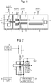
- FIG. 1 is a schematic overall configuration diagram of the mass spectrometer of the first embodiment.
- Fig. 2 is a configuration diagram of the ion source in the same mass spectrometer.
- Fig. 1 the ambience within an ionization chamber 1 is maintained at substantially atmospheric pressure, while the ambience within an analysis chamber 4 is maintained at a high degree of vacuum by evacuation with a high-performance vacuum pump (normally, a turbo molecular pump combined with a rotary pump).
- a high-performance vacuum pump normally, a turbo molecular pump combined with a rotary pump.
- a first intermediate vacuum chamber 2 in which a low vacuum ambience is present
- a second intermediate vacuum chamber 3 whose degree of vacuum is between the first intermediate vacuum chamber 2 and the analysis chamber 4.
- this mass spectrometer has the configuration of a multi-stage differential pumping system with the degree of vacuum increased in a stepwise manner from the ionization chamber 1 in the travelling direction of the ions.
- a liquid sample which contains sample components is sprayed from an ESI ionization probe 5 while receiving an imbalanced polarity of electric charges.
- heated nebulizer gas may be ejected from a nebulizer-gas tube having a hollow cylindrical shape concentrically surrounding the sample-spraying nozzle, as described in Patent Literature 2, to assist the spraying of the sample solution.
- the electrically charged droplets sprayed from the tip of the ionization probe 5 are broken into finer droplets by coming into contact with the ambient gas, with the solvent vaporizing from those droplets. During this process, the sample components carrying electric charges are ejected from the droplets, forming ions.
- An auxiliary electrode 6 and reflecting electrode 7, which have respective functions (as will be described later), are provided anterior to the spray flow from the ionization probe 5.
- the ionization chamber 1 and the first intermediate vacuum chamber 2 communicate with each other through a thin heated capillary 8, which corresponds to the ion introduction section in the present invention.
- a pressure difference between the two open ends of this heated capillary 8 and this pressure difference creates a gas stream flowing from the ionization chamber 1 into the first intermediate vacuum chamber 2 through the heated capillary 8.
- the ions generated from the sample components within the ionization chamber 1 are carried mainly by this gas stream and drawn into the heated capillary 8, to be ejected from the outlet end of the same capillary into the first intermediate vacuum chamber 2 along with the gas stream.
- a skimmer 10 having a small orifice at its apex is provided in a partition wall which separates the first intermediate vacuum chamber 2 and the second intermediate vacuum chamber 3.
- the first intermediate vacuum chamber 2 contains an ion guide 9 composed of multiple plate electrodes arranged around the ion beam axis C. Due to the effect of the electric field created by this ion guide 9, the ions introduced into the first intermediate vacuum chamber 2 are converged onto the vicinity of the orifice of the skimmer 10, to be sent through the orifice into the second intermediate vacuum chamber 3.
- the second intermediate vacuum chamber 3 contains a multipole (e.g. octapole) ion guide 11. Due to the effect of a radiofrequency electric field created by this ion guide 11, the ions are converged and sent into the analysis chamber 4. Within the analysis chamber 4, the ions are introduced into a space extending along the longitudinal axis of a quadrupole mass filter 12. Due to the effect of the electric field created by a radiofrequency voltage and direct-current voltage applied to the quadrupole mass filter 12, only ions having a specific mass-to-charge ratio are allowed to pass through the quadrupole mass filter 12 and reach an ion detector 13.
- a multipole e.g. octapole
- the ion detector 13 produces detection signals corresponding to the amount of ions which have reached the detector, and feeds the signals to a data processing unit (not shown).
- an auxiliary electrode 6 is located closest to the ionization probe 5, along with a reflecting electrode 7 located farther from the ionization probe 5 and at distance a from the auxiliary electrode 6.
- both auxiliary electrode 6 and reflecting electrode 7 are shaped like a hollow circular cylinder and concentrically arranged with the central axis of the spray flow from the ionization probe 5.
- the heated capillary 8 is provided so that its inlet end 8a projects into the space between the two electrodes 6 and 7.
- the auxiliary electrode 6, inlet end 8a of the heated capillary 8, and reflecting electrode 7 arranged in the mentioned order.
- the spray flow which moves spreading in a substantially conical form passes through the hollow area of the auxiliary electrode 6 (the space surrounded by the auxiliary electrode 6) and that of the reflecting electrode 7 (the space surrounded by the reflecting electrode 7) in the mentioned order.
- the auxiliary and reflecting electrodes 6 and 7 have the same inner diameter, although their inner diameters do not always need to be the same.
- the shape of the electrodes 6 and 7 may be different from a hollow circular cylinder. For example, they may be shaped like a hollow polygonal cylinder.
- the auxiliary electrode 6, and the electrically conductive partition wall which is electrically connected to the heated capillary 8, are grounded, whereas the reflecting electrode 7 is supplied with a direct-current voltage from a reflecting electrode power source 21.
- a high direct-current voltage with a maximum level of approximately several kV is applied from a nozzle power source 20.
- the polarity of each of the voltages respectively applied to the reflecting electrode 7 and the ionization probe 5 is selected according to the polarity of the measurement target ion; when the measurement target ion is a positive ion, both voltages have the positive polarity.
- the voltages generated by the nozzle power source 20 and the reflecting electrode power source 21 are controlled by a controller 22.
- the measurement target ion is a positive ion.
- the measurement target ion is a negative ion, only the polarity of the applied voltages only needs to be changed.
- the motion of an ion in an ambience of atmospheric pressure depends on the strength of the gas flow and that of the electric field.
- K is the ion mobility.
- the ion mobility is a parameter which determines the moving velocity of the ion due to an electric field taking into account the collision with neutral particles. This parameter depends on the mass, valence and collision cross-section with neutral particles of the ion as well as the gas temperature and other factors. According to a report in Non Patent Literature 1, an ion having a mass-to-charge ratio (m/z) of approximately 500 has an ion mobility of 1 ⁇ 10 -4 m 2 /Vs.
- Most of the particles sprayed from the ionization probe 5 are considered to be in the form of electrically charged micro particles containing the solvent. Since those particles are larger in size than their ionized form, it is possible to consider that the mobility of those particles is lower than the value of the mobility for an ion calculated in the aforementioned manner. It can also be inferred that the mobility of those charged droplets gradually becomes closer to the value of the ion, since their size decreases with the progress of the desolvation during their flight in the ambience of atmospheric pressure.
- the velocity of the gas flow ejected from the ionization probe 5 reaches several tens of m/s in an area near the inlet end 8a of the heated capillary 8.
- a focusing electric field directed to the ion introduction port is generated by setting the potential of the ion introduction port at a lower level than a nearby electrode (e.g. the tip portion of the ionization probe).
- a nearby electrode e.g. the tip portion of the ionization probe
- the mass spectrometer according to the present embodiment is provided with the auxiliary and reflecting electrodes 6 and 7 for efficiently generating an electric field in the opposite direction to the gas flow.
- the spray flow ejected from the ionization probe 5 travels downward. Ions generated from the sample droplets also travel in approximately the same direction.
- a reflecting electric field which acts on the ions to repel them upward is created within the space between the auxiliary and reflecting electrodes 6 and 7 by the direct-current voltage applied from the reflecting electrode power source 21 to the reflecting electrode 7.
- a strong electric field which acts on the ions in the opposite direction to the gas slow can be created in an area near the inlet end 8a.
- a strong electric field having the aforementioned strength of approximately 4 kV/cm can be created by applying an appropriate voltage of equal to or lower than roughly 3 kV to the reflecting electrode 7, with the leakage of the electric field considered.
- ions and charged droplets carried by the spray flow and travelling downward are separated from the gas flow and repelled upward due to the aforementioned strong reflecting electric field, being suspended near the inlet end 8a of the heated capillary 8. Then, due to the focusing electric field, they are attracted toward the vicinity of the inlet end 8a of the heated capillary 8. Those ions and charged droplets collected in the vicinity of the inlet end 8a of the heated capillary 8 are carried by the stream of gas flowing through the heated capillary 8, to be drawn into the heated capillary 8 and sent to the first intermediate vacuum chamber 2.
- a macroscopic moving velocity of an ion in a gas flow under an electric field can be approximately given by equation (1). Accordingly, the macroscopic motion of the ion can be simulated by calculating the gas-flow velocity and the electric field, and then computing the velocity field of the ions by combining the calculated gas-flow velocity and electric field.
- the ionization probe 5 was a commonly used ESI ionization probe having the coaxial and cylindrical heating-gas mechanism.
- a nebulizer gas for promoting the scattering and atomization of the droplets at the tip portion of the ionization probe 5
- a heated gas coaxially and cylindrically sprayed around the nebulizer gas.
- the flows of those gases were computed by hydrodynamic simulations.
- the auxiliary electrode 6, reflecting electrode 7 and heated capillary 8 an arrangement of as shown in Fig. 2 was assumed to simulate the electric field.
- Figs. 4A and 4B show the simulation result of the direction of the forces due to the electric field.
- Figs. 5A and 5B show the simulation result of the gas flow.
- Figs. 3A and 3B show the simulation results of the ion trajectories based on equation (1) using the simulation result of the gas flow and that of the electric field.
- the reflecting electrode 7 is supplied with no voltage and given the ground potential as with the auxiliary electrode 6, the system can effectively be considered to be equivalent to a prior-art system which has no reflecting electrode 7.
- Fig. 3A shows the ion trajectories under such a condition
- Fig. 3B shows the ion trajectories under the condition a direct-current voltage of 3.6 kV was applied to the reflecting electrode 7.
- the efficiency of collecting the ions to the inlet end 8a of the heated capillary 8 depends on the strength of the reflecting electric field and the ion mobility.
- the ion mobility depends on the mass-to-charge ratio of the ion. Therefore, in order to improve the sensitivity of the analysis, it is effective to change the voltage applied to the reflecting electrode 7 according to the mass-to-charge ratio of the ion to be selected by the quadrupole mass filter 12 (i.e. the measurement target ion).
- FIG. 9 is a graph showing the result of a simulation of the number of ions having a specific mass-to-charge ratio reaching the inlet end 8a of the heated capillary 8 for various values of the voltage applied to the reflecting electrode 7 (reflecting voltage). It can be seen that there is an optimum value of the reflecting voltage for this ion, and a deviation from that optimum value lowers the ion collection efficiency.
- the optimum reflecting voltage is experimentally determined beforehand for each of the mass-to-charge ratios of the measurement target ions, and a calculation formula or table showing the relationship between the mass-to-charge ratio and the optimum reflecting voltage is created and stored in the controller 22.
- the controller 22 determines, based on the aforementioned calculation formula or table, the optimum reflecting voltage according to the voltage applied to the quadrupole mass filter 12 (i.e. according to the mass-to-charge ratio of the ion to be selected with the quadruple mass filter 12) and controls the reflecting electrode power source 21 so that the voltage applied to the reflecting electrode 7 becomes equal to the optimum reflecting voltage.
- the reflecting voltage is also changed synchronously with the scan operation.
- ions are introduced into the first intermediate vacuum chamber 2 and subsequent sections with high efficiency over the entire range of mass-to-charge ratios.
- the auxiliary electrode 6, reflecting electrode 7 and heated capillary 8 as an ion mobility spectrometry unit for changing the mobility of an ion to be monitored, or to use it as an ion mobility filter for selecting ions having a specific mobility.
- the intensities of various ions which have a specific mass-to-charge ratio yet differ from each other in ion mobility can be determined by continuously changing the voltage applied to the reflecting electrode 7, with the mass-to-charge ratio of the ion to be selected by the quadrupole mass filter 12 fixed.
- FIG. 6A is a configuration diagram of the ion source in the mass spectrometer of the second embodiment.
- Fig. 6B is a top view of the auxiliary electrode 60.
- the same components as used in the mass spectrometer of the first embodiment are denoted by the same numerals.
- the mass spectrometer of the first embodiment when the flow velocity of the gas flow ejected from the ionization probe 5 is higher, a higher reflecting voltage is needed to separate ions from the gas flow and repel them.
- the mass spectrometer of the second embodiment is characterized in that the auxiliary electrode 60 maintained at ground potential is provided with a gas ejection mechanism in order to obtain the ion collection effect with a lower reflecting voltage.
- the gas ejection mechanism includes a blocking gas outlet 62 shaped like a slit extending along the entire circumference on the inner circumferential wall of the auxiliary electrode 60, and a gas passage 61 for guiding an externally supplied gas to the blocking gas outlet 62.
- This gas may be an inert gas similar to the nebulizer gas or the like.
- the ring-shaped blocking gas outlet 62 ejects the gas toward the cylindrical axis of the auxiliary electrode 60, forming a curtain-like stream of gas blocking the spray flow ejected from the ionization probe 5, in a roughly orthogonal direction to this spray flow. This lowers the flow velocity of the spray flow ejected from the ionization probe 5.
- the ions and charged droplets contained in the spray flow are focused onto an area near the central axis, being prevented from diffusing outwards. This helps the reflecting and focusing electric fields to exhibit their focusing effect.
- the direction of the gas ejected from the blocking gas outlet 62 is substantially orthogonal to the central axis of the auxiliary electrode 60, i.e. the central axis of the spray flow from the ionization probe 5.
- the blocking gas outlet 62 may be designed to eject the gas obliquely upward. This makes the gas ejected from the blocking gas outlet 62 move against the spray flow from the ionization probe 5, producing an even higher effect of reduces the gas flow velocity due to the spray flow.
- this configuration unfavorably lowers the effect of focusing the ions and charged droplets in the spray flow onto an area near the central axis. Accordingly, the direction of the blocking gas outlet 62 should be adjusted so that the gas ejected from it collides with the spray flow at an appropriate angle.
- Fig. 7 is a schematic configuration diagram of the ion mobility spectrometer of the present embodiment.
- a change in the voltage applied to the reflecting electrode 7 causes a change in the efficiency for an ion having a specific mass-to-charge ratio to reach the inlet end 8a of the heated capillary 8. That is to say, the efficiency of collecting ions to the inlet end 8a of the heated capillary 8 has a dependency on the ion mobility.
- the ion mobility spectrometer of the present embodiment separates and detects ions according to the ion mobility.
- an ion detection electrode 30 is provided at the location where the inlet end 8a of the heated capillary 8 was located in the mass spectrometer of the first embodiment.
- An ion current obtained with the ion detection electrode 30 is amplified by an amplifier 31 and provided as a detection signal.
- the controller 23 operates the reflecting electrode power source 21 so that the voltage applied to the reflecting electrode 7 is continuously changed over a predetermined range. With this operation, the mobility of the ion which can most efficiently reach the ion detection electrode 30 also changes. Therefore, an ion mobility spectrum can be created based on the detection signal.
- the controller 23 When a temporal change in the ion intensity of the ions having a specific ion mobility needs to be monitored, the controller 23 operates the reflecting electrode power source 21 so that a voltage corresponding to the ion mobility of that ion is applied to the reflecting electrode 7. By this operation, the state in which the ions having that specific ion mobility can most efficiently reach the ion detection electrode 30 is maintained. Therefore, a chromatogram for ions having that specific ion mobility can be created based on the detection signal.
- ion mobility spectrometers can separate ions with high resolving power according to the ion mobility.
- those systems are large in scale due to such factors as a complex electrode configuration for creating electric fields as well as a complex structure for generating a gas flow with a constant flow velocity.
- the section for separating ions according to their mobility has an extremely simple configuration and allows for the realization of a small and inexpensive device. Therefore, for example, a system which is suitable as an option for a detector for liquid chromatographs can be provided.
- Fig. 8 is an ion mobility spectrometer in which the ion detection electrode 30 is provided at the location where the inlet end 8a of the heated capillary 8 was located in the mass spectrometer of the second embodiment shown in Figs. 6A and 6B .
- the mass spectrometer of the second embodiment in the ion mobility spectrometer of the fourth embodiment, when the flow velocity of the spray flow ejected from the ionization probe 5 is high, the flow velocity can be reduced by the effect of the curtain-like blocking gas, allowing the voltage applied to the reflecting electrode 7 to be decreased.
Landscapes
- Chemical & Material Sciences (AREA)
- Analytical Chemistry (AREA)
- Physics & Mathematics (AREA)
- Health & Medical Sciences (AREA)
- Life Sciences & Earth Sciences (AREA)
- Spectroscopy & Molecular Physics (AREA)
- Immunology (AREA)
- Electrochemistry (AREA)
- Biochemistry (AREA)
- General Health & Medical Sciences (AREA)
- General Physics & Mathematics (AREA)
- Chemical Kinetics & Catalysis (AREA)
- Pathology (AREA)
- Engineering & Computer Science (AREA)
- Plasma & Fusion (AREA)
- Molecular Biology (AREA)
- Dispersion Chemistry (AREA)
- Other Investigation Or Analysis Of Materials By Electrical Means (AREA)
- Electron Tubes For Measurement (AREA)
Applications Claiming Priority (1)
| Application Number | Priority Date | Filing Date | Title |
|---|---|---|---|
| PCT/JP2015/051622 WO2016117066A1 (ja) | 2015-01-22 | 2015-01-22 | 質量分析装置及びイオン移動度分析装置 |
Publications (3)
| Publication Number | Publication Date |
|---|---|
| EP3249679A1 true EP3249679A1 (de) | 2017-11-29 |
| EP3249679A4 EP3249679A4 (de) | 2018-01-17 |
| EP3249679B1 EP3249679B1 (de) | 2024-04-24 |
Family
ID=56416632
Family Applications (1)
| Application Number | Title | Priority Date | Filing Date |
|---|---|---|---|
| EP15878760.6A Active EP3249679B1 (de) | 2015-01-22 | 2015-01-22 | Massenspektrometer und ionenmobilitätsanalysator |
Country Status (5)
| Country | Link |
|---|---|
| US (1) | US10281433B2 (de) |
| EP (1) | EP3249679B1 (de) |
| JP (1) | JP6319466B2 (de) |
| CN (1) | CN107210182B (de) |
| WO (1) | WO2016117066A1 (de) |
Cited By (1)
| Publication number | Priority date | Publication date | Assignee | Title |
|---|---|---|---|---|
| GB2590087A (en) * | 2017-04-13 | 2021-06-23 | Micromass Ltd | In-source reduction of biomolecules and their analysis by ION mobility MS/MS |
Families Citing this family (16)
| Publication number | Priority date | Publication date | Assignee | Title |
|---|---|---|---|---|
| JP6593548B2 (ja) * | 2016-10-24 | 2019-10-23 | 株式会社島津製作所 | 質量分析装置及びイオン検出装置 |
| WO2019162853A1 (en) * | 2018-02-20 | 2019-08-29 | Dh Technologies Development Pte. Ltd. | Integrated electrospray ion source |
| US10714301B1 (en) * | 2018-02-21 | 2020-07-14 | Varian Semiconductor Equipment Associates, Inc. | Conductive beam optics for reducing particles in ion implanter |
| JP7247083B2 (ja) * | 2019-12-19 | 2023-03-28 | 株式会社日立ハイテク | イオン源および質量分析計 |
| WO2021161381A1 (ja) * | 2020-02-10 | 2021-08-19 | 株式会社島津製作所 | 質量分析装置 |
| EP4104199A1 (de) * | 2020-02-13 | 2022-12-21 | DH Technologies Development Pte. Ltd. | Elektrospray-ionenquellenanordnung |
| JP7258799B2 (ja) * | 2020-02-27 | 2023-04-17 | 株式会社日立ハイテク | イオン源、質量分析計、イオン源制御方法 |
| CN111665103B (zh) * | 2020-05-13 | 2023-08-18 | 中国科学院微电子研究所 | 一种低真空痕量气体的快速无损采样分析装置和方法 |
| US12266518B2 (en) * | 2020-05-20 | 2025-04-01 | Shimadzu Corporation | Ion analyzer |
| CN115803614B (zh) * | 2020-08-20 | 2024-10-11 | 株式会社岛津制作所 | 质量分析装置 |
| JP7428262B2 (ja) * | 2020-09-04 | 2024-02-06 | 株式会社島津製作所 | イオン分析装置 |
| CN112858452B (zh) * | 2021-01-19 | 2023-10-03 | 岛津企业管理(中国)有限公司 | 一种探针电喷雾离子化与质谱联用的活体分析系统 |
| CN113176325B (zh) * | 2021-04-14 | 2023-05-12 | 北京师范大学 | 一种毫秒内等离子体加速降解有机污染物的常压质谱在线监测系统 |
| CN115372450B (zh) * | 2021-05-19 | 2026-02-27 | 株式会社岛津制作所 | 离子分析装置 |
| CN114068289B (zh) * | 2021-11-24 | 2024-08-06 | 中国科学院大连化学物理研究所 | 一种电喷雾离子化源及应用 |
| WO2024241754A1 (ja) * | 2023-05-22 | 2024-11-28 | 株式会社日立ハイテク | 質量分析装置 |
Family Cites Families (12)
| Publication number | Priority date | Publication date | Assignee | Title |
|---|---|---|---|---|
| US5412208A (en) | 1994-01-13 | 1995-05-02 | Mds Health Group Limited | Ion spray with intersecting flow |
| US6614021B1 (en) * | 1998-09-23 | 2003-09-02 | Varian Australian Pty Ltd | Ion optical system for a mass spectrometer |
| JP4186889B2 (ja) * | 1999-04-15 | 2008-11-26 | 株式会社日立製作所 | 質量分析装置 |
| US6998605B1 (en) * | 2000-05-25 | 2006-02-14 | Agilent Technologies, Inc. | Apparatus for delivering ions from a grounded electrospray assembly to a vacuum chamber |
| US7078681B2 (en) * | 2002-09-18 | 2006-07-18 | Agilent Technologies, Inc. | Multimode ionization source |
| JP2004303497A (ja) * | 2003-03-31 | 2004-10-28 | National Institute Of Advanced Industrial & Technology | 粒子イオン化方法及び装置 |
| GB0512411D0 (en) * | 2005-06-17 | 2005-07-27 | Polaron Plc | Atom probe |
| US20070023677A1 (en) * | 2005-06-29 | 2007-02-01 | Perkins Patrick D | Multimode ionization source and method for screening molecules |
| JP4802032B2 (ja) * | 2006-04-14 | 2011-10-26 | 日本電子株式会社 | タンデム型質量分析装置 |
| JP2009129868A (ja) * | 2007-11-28 | 2009-06-11 | Shimadzu Corp | 質量分析装置及びその調整方法 |
| WO2009124298A2 (en) | 2008-04-04 | 2009-10-08 | Agilent Technologies, Inc. | Ion sources for improved ionization |
| JP6165890B2 (ja) * | 2014-01-27 | 2017-07-19 | 株式会社日立ハイテクノロジーズ | 液体クロマトグラフ質量分析装置 |
-
2015
- 2015-01-22 US US15/545,405 patent/US10281433B2/en active Active
- 2015-01-22 WO PCT/JP2015/051622 patent/WO2016117066A1/ja not_active Ceased
- 2015-01-22 JP JP2016570409A patent/JP6319466B2/ja active Active
- 2015-01-22 CN CN201580074229.2A patent/CN107210182B/zh active Active
- 2015-01-22 EP EP15878760.6A patent/EP3249679B1/de active Active
Cited By (4)
| Publication number | Priority date | Publication date | Assignee | Title |
|---|---|---|---|---|
| GB2590087A (en) * | 2017-04-13 | 2021-06-23 | Micromass Ltd | In-source reduction of biomolecules and their analysis by ION mobility MS/MS |
| GB2590087B (en) * | 2017-04-13 | 2021-12-15 | Micromass Ltd | In-source reduction of biomolecules and their analysis by ion mobility MS/MS |
| US11567087B2 (en) | 2017-04-13 | 2023-01-31 | Micromass Uk Limited | Method of fragmenting and charge reducing biomolecules |
| US11733247B2 (en) | 2017-04-13 | 2023-08-22 | Micromass Uk Limited | Breaking of disulfide bonds of a nebulized analyte |
Also Published As
| Publication number | Publication date |
|---|---|
| EP3249679A4 (de) | 2018-01-17 |
| US20180011057A1 (en) | 2018-01-11 |
| JP6319466B2 (ja) | 2018-05-09 |
| CN107210182A (zh) | 2017-09-26 |
| US10281433B2 (en) | 2019-05-07 |
| JPWO2016117066A1 (ja) | 2017-07-06 |
| WO2016117066A1 (ja) | 2016-07-28 |
| CN107210182B (zh) | 2019-08-27 |
| EP3249679B1 (de) | 2024-04-24 |
Similar Documents
| Publication | Publication Date | Title |
|---|---|---|
| EP3249679B1 (de) | Massenspektrometer und ionenmobilitätsanalysator | |
| US10546740B2 (en) | Mass spectrometry device and ion detection device | |
| CN108511315B (zh) | 碰撞离子发生器和分离器 | |
| US6278110B1 (en) | Orthogonal ion sampling for APCI mass spectrometry | |
| US6649907B2 (en) | Charge reduction electrospray ionization ion source | |
| US6974957B2 (en) | Ionization device for aerosol mass spectrometer and method of ionization | |
| US6498343B2 (en) | Orthogonal ion sampling for APCI mass spectrometry | |
| JP7210536B2 (ja) | 電子イオン化源からのイオンの移動 | |
| US20020166961A1 (en) | Droplet ion source for mass spectrometry | |
| US7642511B2 (en) | Ultra high mass range mass spectrometer systems | |
| WO1997049111A1 (en) | Method and apparatus for ion and charged particle focusing | |
| US8368012B2 (en) | Guiding charged droplets and ions in an electrospray ion source | |
| JP2008524804A (ja) | 最適化乾燥ガス流を用いた常圧イオン化 | |
| JPWO2010143426A1 (ja) | サイクロンセパレータ式質量分析システム | |
| JP2005063770A (ja) | 質量分析装置 |
Legal Events
| Date | Code | Title | Description |
|---|---|---|---|
| STAA | Information on the status of an ep patent application or granted ep patent |
Free format text: STATUS: THE INTERNATIONAL PUBLICATION HAS BEEN MADE |
|
| PUAI | Public reference made under article 153(3) epc to a published international application that has entered the european phase |
Free format text: ORIGINAL CODE: 0009012 |
|
| STAA | Information on the status of an ep patent application or granted ep patent |
Free format text: STATUS: REQUEST FOR EXAMINATION WAS MADE |
|
| 17P | Request for examination filed |
Effective date: 20170810 |
|
| AK | Designated contracting states |
Kind code of ref document: A1 Designated state(s): AL AT BE BG CH CY CZ DE DK EE ES FI FR GB GR HR HU IE IS IT LI LT LU LV MC MK MT NL NO PL PT RO RS SE SI SK SM TR |
|
| AX | Request for extension of the european patent |
Extension state: BA ME |
|
| A4 | Supplementary search report drawn up and despatched |
Effective date: 20171219 |
|
| RIC1 | Information provided on ipc code assigned before grant |
Ipc: H01J 49/10 20060101AFI20171213BHEP Ipc: G01N 27/62 20060101ALI20171213BHEP Ipc: H01J 49/06 20060101ALI20171213BHEP Ipc: H01J 49/16 20060101ALI20171213BHEP |
|
| DAX | Request for extension of the european patent (deleted) | ||
| STAA | Information on the status of an ep patent application or granted ep patent |
Free format text: STATUS: EXAMINATION IS IN PROGRESS |
|
| 17Q | First examination report despatched |
Effective date: 20201015 |
|
| REG | Reference to a national code |
Ref country code: DE Ref legal event code: R079 Free format text: PREVIOUS MAIN CLASS: H01J0049100000 Ipc: H01J0049160000 Ref country code: DE Ref legal event code: R079 Ref document number: 602015088469 Country of ref document: DE Free format text: PREVIOUS MAIN CLASS: H01J0049100000 Ipc: H01J0049160000 |
|
| GRAP | Despatch of communication of intention to grant a patent |
Free format text: ORIGINAL CODE: EPIDOSNIGR1 |
|
| STAA | Information on the status of an ep patent application or granted ep patent |
Free format text: STATUS: GRANT OF PATENT IS INTENDED |
|
| RIC1 | Information provided on ipc code assigned before grant |
Ipc: G01N 27/623 20210101ALI20231113BHEP Ipc: H01J 49/06 20060101ALI20231113BHEP Ipc: H01J 49/16 20060101AFI20231113BHEP |
|
| INTG | Intention to grant announced |
Effective date: 20231201 |
|
| GRAS | Grant fee paid |
Free format text: ORIGINAL CODE: EPIDOSNIGR3 |
|
| GRAA | (expected) grant |
Free format text: ORIGINAL CODE: 0009210 |
|
| STAA | Information on the status of an ep patent application or granted ep patent |
Free format text: STATUS: THE PATENT HAS BEEN GRANTED |
|
| AK | Designated contracting states |
Kind code of ref document: B1 Designated state(s): AL AT BE BG CH CY CZ DE DK EE ES FI FR GB GR HR HU IE IS IT LI LT LU LV MC MK MT NL NO PL PT RO RS SE SI SK SM TR |
|
| REG | Reference to a national code |
Ref country code: GB Ref legal event code: FG4D |
|
| REG | Reference to a national code |
Ref country code: CH Ref legal event code: EP |
|
| REG | Reference to a national code |
Ref country code: DE Ref legal event code: R096 Ref document number: 602015088469 Country of ref document: DE |
|
| REG | Reference to a national code |
Ref country code: IE Ref legal event code: FG4D |
|
| REG | Reference to a national code |
Ref country code: LT Ref legal event code: MG9D |
|
| REG | Reference to a national code |
Ref country code: NL Ref legal event code: MP Effective date: 20240424 |
|
| REG | Reference to a national code |
Ref country code: AT Ref legal event code: MK05 Ref document number: 1680571 Country of ref document: AT Kind code of ref document: T Effective date: 20240424 |
|
| PG25 | Lapsed in a contracting state [announced via postgrant information from national office to epo] |
Ref country code: NL Free format text: LAPSE BECAUSE OF FAILURE TO SUBMIT A TRANSLATION OF THE DESCRIPTION OR TO PAY THE FEE WITHIN THE PRESCRIBED TIME-LIMIT Effective date: 20240424 |
|
| PG25 | Lapsed in a contracting state [announced via postgrant information from national office to epo] |
Ref country code: NL Free format text: LAPSE BECAUSE OF FAILURE TO SUBMIT A TRANSLATION OF THE DESCRIPTION OR TO PAY THE FEE WITHIN THE PRESCRIBED TIME-LIMIT Effective date: 20240424 |
|
| PG25 | Lapsed in a contracting state [announced via postgrant information from national office to epo] |
Ref country code: IS Free format text: LAPSE BECAUSE OF FAILURE TO SUBMIT A TRANSLATION OF THE DESCRIPTION OR TO PAY THE FEE WITHIN THE PRESCRIBED TIME-LIMIT Effective date: 20240824 |
|
| PG25 | Lapsed in a contracting state [announced via postgrant information from national office to epo] |
Ref country code: BG Free format text: LAPSE BECAUSE OF FAILURE TO SUBMIT A TRANSLATION OF THE DESCRIPTION OR TO PAY THE FEE WITHIN THE PRESCRIBED TIME-LIMIT Effective date: 20240424 |
|
| PG25 | Lapsed in a contracting state [announced via postgrant information from national office to epo] |
Ref country code: HR Free format text: LAPSE BECAUSE OF FAILURE TO SUBMIT A TRANSLATION OF THE DESCRIPTION OR TO PAY THE FEE WITHIN THE PRESCRIBED TIME-LIMIT Effective date: 20240424 Ref country code: FI Free format text: LAPSE BECAUSE OF FAILURE TO SUBMIT A TRANSLATION OF THE DESCRIPTION OR TO PAY THE FEE WITHIN THE PRESCRIBED TIME-LIMIT Effective date: 20240424 |
|
| PG25 | Lapsed in a contracting state [announced via postgrant information from national office to epo] |
Ref country code: GR Free format text: LAPSE BECAUSE OF FAILURE TO SUBMIT A TRANSLATION OF THE DESCRIPTION OR TO PAY THE FEE WITHIN THE PRESCRIBED TIME-LIMIT Effective date: 20240725 |
|
| PG25 | Lapsed in a contracting state [announced via postgrant information from national office to epo] |
Ref country code: PT Free format text: LAPSE BECAUSE OF FAILURE TO SUBMIT A TRANSLATION OF THE DESCRIPTION OR TO PAY THE FEE WITHIN THE PRESCRIBED TIME-LIMIT Effective date: 20240826 |
|
| PG25 | Lapsed in a contracting state [announced via postgrant information from national office to epo] |
Ref country code: ES Free format text: LAPSE BECAUSE OF FAILURE TO SUBMIT A TRANSLATION OF THE DESCRIPTION OR TO PAY THE FEE WITHIN THE PRESCRIBED TIME-LIMIT Effective date: 20240424 |
|
| PG25 | Lapsed in a contracting state [announced via postgrant information from national office to epo] |
Ref country code: AT Free format text: LAPSE BECAUSE OF FAILURE TO SUBMIT A TRANSLATION OF THE DESCRIPTION OR TO PAY THE FEE WITHIN THE PRESCRIBED TIME-LIMIT Effective date: 20240424 |
|
| PG25 | Lapsed in a contracting state [announced via postgrant information from national office to epo] |
Ref country code: PL Free format text: LAPSE BECAUSE OF FAILURE TO SUBMIT A TRANSLATION OF THE DESCRIPTION OR TO PAY THE FEE WITHIN THE PRESCRIBED TIME-LIMIT Effective date: 20240424 |
|
| PG25 | Lapsed in a contracting state [announced via postgrant information from national office to epo] |
Ref country code: LV Free format text: LAPSE BECAUSE OF FAILURE TO SUBMIT A TRANSLATION OF THE DESCRIPTION OR TO PAY THE FEE WITHIN THE PRESCRIBED TIME-LIMIT Effective date: 20240424 |
|
| PG25 | Lapsed in a contracting state [announced via postgrant information from national office to epo] |
Ref country code: PT Free format text: LAPSE BECAUSE OF FAILURE TO SUBMIT A TRANSLATION OF THE DESCRIPTION OR TO PAY THE FEE WITHIN THE PRESCRIBED TIME-LIMIT Effective date: 20240826 Ref country code: PL Free format text: LAPSE BECAUSE OF FAILURE TO SUBMIT A TRANSLATION OF THE DESCRIPTION OR TO PAY THE FEE WITHIN THE PRESCRIBED TIME-LIMIT Effective date: 20240424 Ref country code: NO Free format text: LAPSE BECAUSE OF FAILURE TO SUBMIT A TRANSLATION OF THE DESCRIPTION OR TO PAY THE FEE WITHIN THE PRESCRIBED TIME-LIMIT Effective date: 20240724 Ref country code: LV Free format text: LAPSE BECAUSE OF FAILURE TO SUBMIT A TRANSLATION OF THE DESCRIPTION OR TO PAY THE FEE WITHIN THE PRESCRIBED TIME-LIMIT Effective date: 20240424 Ref country code: IS Free format text: LAPSE BECAUSE OF FAILURE TO SUBMIT A TRANSLATION OF THE DESCRIPTION OR TO PAY THE FEE WITHIN THE PRESCRIBED TIME-LIMIT Effective date: 20240824 Ref country code: HR Free format text: LAPSE BECAUSE OF FAILURE TO SUBMIT A TRANSLATION OF THE DESCRIPTION OR TO PAY THE FEE WITHIN THE PRESCRIBED TIME-LIMIT Effective date: 20240424 Ref country code: GR Free format text: LAPSE BECAUSE OF FAILURE TO SUBMIT A TRANSLATION OF THE DESCRIPTION OR TO PAY THE FEE WITHIN THE PRESCRIBED TIME-LIMIT Effective date: 20240725 Ref country code: FI Free format text: LAPSE BECAUSE OF FAILURE TO SUBMIT A TRANSLATION OF THE DESCRIPTION OR TO PAY THE FEE WITHIN THE PRESCRIBED TIME-LIMIT Effective date: 20240424 Ref country code: ES Free format text: LAPSE BECAUSE OF FAILURE TO SUBMIT A TRANSLATION OF THE DESCRIPTION OR TO PAY THE FEE WITHIN THE PRESCRIBED TIME-LIMIT Effective date: 20240424 Ref country code: BG Free format text: LAPSE BECAUSE OF FAILURE TO SUBMIT A TRANSLATION OF THE DESCRIPTION OR TO PAY THE FEE WITHIN THE PRESCRIBED TIME-LIMIT Effective date: 20240424 Ref country code: AT Free format text: LAPSE BECAUSE OF FAILURE TO SUBMIT A TRANSLATION OF THE DESCRIPTION OR TO PAY THE FEE WITHIN THE PRESCRIBED TIME-LIMIT Effective date: 20240424 Ref country code: RS Free format text: LAPSE BECAUSE OF FAILURE TO SUBMIT A TRANSLATION OF THE DESCRIPTION OR TO PAY THE FEE WITHIN THE PRESCRIBED TIME-LIMIT Effective date: 20240724 |
|
| PG25 | Lapsed in a contracting state [announced via postgrant information from national office to epo] |
Ref country code: DK Free format text: LAPSE BECAUSE OF FAILURE TO SUBMIT A TRANSLATION OF THE DESCRIPTION OR TO PAY THE FEE WITHIN THE PRESCRIBED TIME-LIMIT Effective date: 20240424 |
|
| PGFP | Annual fee paid to national office [announced via postgrant information from national office to epo] |
Ref country code: GB Payment date: 20241128 Year of fee payment: 11 |
|
| PG25 | Lapsed in a contracting state [announced via postgrant information from national office to epo] |
Ref country code: EE Free format text: LAPSE BECAUSE OF FAILURE TO SUBMIT A TRANSLATION OF THE DESCRIPTION OR TO PAY THE FEE WITHIN THE PRESCRIBED TIME-LIMIT Effective date: 20240424 |
|
| PG25 | Lapsed in a contracting state [announced via postgrant information from national office to epo] |
Ref country code: CZ Free format text: LAPSE BECAUSE OF FAILURE TO SUBMIT A TRANSLATION OF THE DESCRIPTION OR TO PAY THE FEE WITHIN THE PRESCRIBED TIME-LIMIT Effective date: 20240424 |
|
| PG25 | Lapsed in a contracting state [announced via postgrant information from national office to epo] |
Ref country code: RO Free format text: LAPSE BECAUSE OF FAILURE TO SUBMIT A TRANSLATION OF THE DESCRIPTION OR TO PAY THE FEE WITHIN THE PRESCRIBED TIME-LIMIT Effective date: 20240424 Ref country code: SK Free format text: LAPSE BECAUSE OF FAILURE TO SUBMIT A TRANSLATION OF THE DESCRIPTION OR TO PAY THE FEE WITHIN THE PRESCRIBED TIME-LIMIT Effective date: 20240424 |
|
| REG | Reference to a national code |
Ref country code: DE Ref legal event code: R097 Ref document number: 602015088469 Country of ref document: DE |
|
| PG25 | Lapsed in a contracting state [announced via postgrant information from national office to epo] |
Ref country code: SM Free format text: LAPSE BECAUSE OF FAILURE TO SUBMIT A TRANSLATION OF THE DESCRIPTION OR TO PAY THE FEE WITHIN THE PRESCRIBED TIME-LIMIT Effective date: 20240424 |
|
| PG25 | Lapsed in a contracting state [announced via postgrant information from national office to epo] |
Ref country code: SM Free format text: LAPSE BECAUSE OF FAILURE TO SUBMIT A TRANSLATION OF THE DESCRIPTION OR TO PAY THE FEE WITHIN THE PRESCRIBED TIME-LIMIT Effective date: 20240424 Ref country code: SK Free format text: LAPSE BECAUSE OF FAILURE TO SUBMIT A TRANSLATION OF THE DESCRIPTION OR TO PAY THE FEE WITHIN THE PRESCRIBED TIME-LIMIT Effective date: 20240424 Ref country code: RO Free format text: LAPSE BECAUSE OF FAILURE TO SUBMIT A TRANSLATION OF THE DESCRIPTION OR TO PAY THE FEE WITHIN THE PRESCRIBED TIME-LIMIT Effective date: 20240424 Ref country code: EE Free format text: LAPSE BECAUSE OF FAILURE TO SUBMIT A TRANSLATION OF THE DESCRIPTION OR TO PAY THE FEE WITHIN THE PRESCRIBED TIME-LIMIT Effective date: 20240424 Ref country code: DK Free format text: LAPSE BECAUSE OF FAILURE TO SUBMIT A TRANSLATION OF THE DESCRIPTION OR TO PAY THE FEE WITHIN THE PRESCRIBED TIME-LIMIT Effective date: 20240424 Ref country code: CZ Free format text: LAPSE BECAUSE OF FAILURE TO SUBMIT A TRANSLATION OF THE DESCRIPTION OR TO PAY THE FEE WITHIN THE PRESCRIBED TIME-LIMIT Effective date: 20240424 |
|
| PLBE | No opposition filed within time limit |
Free format text: ORIGINAL CODE: 0009261 |
|
| STAA | Information on the status of an ep patent application or granted ep patent |
Free format text: STATUS: NO OPPOSITION FILED WITHIN TIME LIMIT |
|
| 26N | No opposition filed |
Effective date: 20250127 |
|
| PGFP | Annual fee paid to national office [announced via postgrant information from national office to epo] |
Ref country code: DE Payment date: 20241203 Year of fee payment: 11 |
|
| PG25 | Lapsed in a contracting state [announced via postgrant information from national office to epo] |
Ref country code: SI Free format text: LAPSE BECAUSE OF FAILURE TO SUBMIT A TRANSLATION OF THE DESCRIPTION OR TO PAY THE FEE WITHIN THE PRESCRIBED TIME-LIMIT Effective date: 20240424 |
|
| REG | Reference to a national code |
Ref country code: CH Ref legal event code: PL |
|
| PG25 | Lapsed in a contracting state [announced via postgrant information from national office to epo] |
Ref country code: SE Free format text: LAPSE BECAUSE OF FAILURE TO SUBMIT A TRANSLATION OF THE DESCRIPTION OR TO PAY THE FEE WITHIN THE PRESCRIBED TIME-LIMIT Effective date: 20240424 |
|
| PG25 | Lapsed in a contracting state [announced via postgrant information from national office to epo] |
Ref country code: MC Free format text: LAPSE BECAUSE OF FAILURE TO SUBMIT A TRANSLATION OF THE DESCRIPTION OR TO PAY THE FEE WITHIN THE PRESCRIBED TIME-LIMIT Effective date: 20240424 Ref country code: LU Free format text: LAPSE BECAUSE OF NON-PAYMENT OF DUE FEES Effective date: 20250122 |
|
| PG25 | Lapsed in a contracting state [announced via postgrant information from national office to epo] |
Ref country code: BE Free format text: LAPSE BECAUSE OF NON-PAYMENT OF DUE FEES Effective date: 20250131 |
|
| PG25 | Lapsed in a contracting state [announced via postgrant information from national office to epo] |
Ref country code: FR Free format text: LAPSE BECAUSE OF NON-PAYMENT OF DUE FEES Effective date: 20250131 |
|
| PG25 | Lapsed in a contracting state [announced via postgrant information from national office to epo] |
Ref country code: CH Free format text: LAPSE BECAUSE OF NON-PAYMENT OF DUE FEES Effective date: 20250131 |
|
| REG | Reference to a national code |
Ref country code: BE Ref legal event code: MM Effective date: 20250131 |
|
| PG25 | Lapsed in a contracting state [announced via postgrant information from national office to epo] |
Ref country code: IE Free format text: LAPSE BECAUSE OF NON-PAYMENT OF DUE FEES Effective date: 20250122 |
|
| PG25 | Lapsed in a contracting state [announced via postgrant information from national office to epo] |
Ref country code: IT Free format text: LAPSE BECAUSE OF FAILURE TO SUBMIT A TRANSLATION OF THE DESCRIPTION OR TO PAY THE FEE WITHIN THE PRESCRIBED TIME-LIMIT Effective date: 20240424 |