EP3249737B1 - Batterie, système, procédé de gestion de batterie, programme de gestion de batterie, et support d'enregistrement - Google Patents
Batterie, système, procédé de gestion de batterie, programme de gestion de batterie, et support d'enregistrement Download PDFInfo
- Publication number
- EP3249737B1 EP3249737B1 EP16761371.0A EP16761371A EP3249737B1 EP 3249737 B1 EP3249737 B1 EP 3249737B1 EP 16761371 A EP16761371 A EP 16761371A EP 3249737 B1 EP3249737 B1 EP 3249737B1
- Authority
- EP
- European Patent Office
- Prior art keywords
- battery
- damage
- physical load
- information
- sensor
- Prior art date
- Legal status (The legal status is an assumption and is not a legal conclusion. Google has not performed a legal analysis and makes no representation as to the accuracy of the status listed.)
- Active
Links
Images


Classifications
-
- B—PERFORMING OPERATIONS; TRANSPORTING
- B60—VEHICLES IN GENERAL
- B60L—PROPULSION OF ELECTRICALLY-PROPELLED VEHICLES; SUPPLYING ELECTRIC POWER FOR AUXILIARY EQUIPMENT OF ELECTRICALLY-PROPELLED VEHICLES; ELECTRODYNAMIC BRAKE SYSTEMS FOR VEHICLES IN GENERAL; MAGNETIC SUSPENSION OR LEVITATION FOR VEHICLES; MONITORING OPERATING VARIABLES OF ELECTRICALLY-PROPELLED VEHICLES; ELECTRIC SAFETY DEVICES FOR ELECTRICALLY-PROPELLED VEHICLES
- B60L58/00—Methods or circuit arrangements for monitoring or controlling batteries or fuel cells, specially adapted for electric vehicles
- B60L58/10—Methods or circuit arrangements for monitoring or controlling batteries or fuel cells, specially adapted for electric vehicles for monitoring or controlling batteries
- B60L58/24—Methods or circuit arrangements for monitoring or controlling batteries or fuel cells, specially adapted for electric vehicles for monitoring or controlling batteries for controlling the temperature of batteries
-
- B—PERFORMING OPERATIONS; TRANSPORTING
- B60—VEHICLES IN GENERAL
- B60L—PROPULSION OF ELECTRICALLY-PROPELLED VEHICLES; SUPPLYING ELECTRIC POWER FOR AUXILIARY EQUIPMENT OF ELECTRICALLY-PROPELLED VEHICLES; ELECTRODYNAMIC BRAKE SYSTEMS FOR VEHICLES IN GENERAL; MAGNETIC SUSPENSION OR LEVITATION FOR VEHICLES; MONITORING OPERATING VARIABLES OF ELECTRICALLY-PROPELLED VEHICLES; ELECTRIC SAFETY DEVICES FOR ELECTRICALLY-PROPELLED VEHICLES
- B60L3/00—Electric devices on electrically-propelled vehicles for safety purposes; Monitoring operating variables, e.g. speed, deceleration or energy consumption
- B60L3/0007—Measures or means for preventing or attenuating collisions
- B60L3/0015—Prevention of collisions
-
- B—PERFORMING OPERATIONS; TRANSPORTING
- B60—VEHICLES IN GENERAL
- B60L—PROPULSION OF ELECTRICALLY-PROPELLED VEHICLES; SUPPLYING ELECTRIC POWER FOR AUXILIARY EQUIPMENT OF ELECTRICALLY-PROPELLED VEHICLES; ELECTRODYNAMIC BRAKE SYSTEMS FOR VEHICLES IN GENERAL; MAGNETIC SUSPENSION OR LEVITATION FOR VEHICLES; MONITORING OPERATING VARIABLES OF ELECTRICALLY-PROPELLED VEHICLES; ELECTRIC SAFETY DEVICES FOR ELECTRICALLY-PROPELLED VEHICLES
- B60L3/00—Electric devices on electrically-propelled vehicles for safety purposes; Monitoring operating variables, e.g. speed, deceleration or energy consumption
- B60L3/0023—Detecting, eliminating, remedying or compensating for drive train abnormalities, e.g. failures within the drive train
- B60L3/0046—Detecting, eliminating, remedying or compensating for drive train abnormalities, e.g. failures within the drive train relating to electric energy storage systems, e.g. batteries or capacitors
-
- B—PERFORMING OPERATIONS; TRANSPORTING
- B60—VEHICLES IN GENERAL
- B60L—PROPULSION OF ELECTRICALLY-PROPELLED VEHICLES; SUPPLYING ELECTRIC POWER FOR AUXILIARY EQUIPMENT OF ELECTRICALLY-PROPELLED VEHICLES; ELECTRODYNAMIC BRAKE SYSTEMS FOR VEHICLES IN GENERAL; MAGNETIC SUSPENSION OR LEVITATION FOR VEHICLES; MONITORING OPERATING VARIABLES OF ELECTRICALLY-PROPELLED VEHICLES; ELECTRIC SAFETY DEVICES FOR ELECTRICALLY-PROPELLED VEHICLES
- B60L50/00—Electric propulsion with power supplied within the vehicle
- B60L50/50—Electric propulsion with power supplied within the vehicle using propulsion power supplied by batteries or fuel cells
- B60L50/60—Electric propulsion with power supplied within the vehicle using propulsion power supplied by batteries or fuel cells using power supplied by batteries
- B60L50/64—Constructional details of batteries specially adapted for electric vehicles
-
- B—PERFORMING OPERATIONS; TRANSPORTING
- B60—VEHICLES IN GENERAL
- B60L—PROPULSION OF ELECTRICALLY-PROPELLED VEHICLES; SUPPLYING ELECTRIC POWER FOR AUXILIARY EQUIPMENT OF ELECTRICALLY-PROPELLED VEHICLES; ELECTRODYNAMIC BRAKE SYSTEMS FOR VEHICLES IN GENERAL; MAGNETIC SUSPENSION OR LEVITATION FOR VEHICLES; MONITORING OPERATING VARIABLES OF ELECTRICALLY-PROPELLED VEHICLES; ELECTRIC SAFETY DEVICES FOR ELECTRICALLY-PROPELLED VEHICLES
- B60L53/00—Methods of charging batteries, specially adapted for electric vehicles; Charging stations or on-board charging equipment therefor; Exchange of energy storage elements in electric vehicles
- B60L53/80—Exchanging energy storage elements, e.g. removable batteries
-
- G—PHYSICS
- G01—MEASURING; TESTING
- G01L—MEASURING FORCE, STRESS, TORQUE, WORK, MECHANICAL POWER, MECHANICAL EFFICIENCY, OR FLUID PRESSURE
- G01L5/00—Apparatus for, or methods of, measuring force, work, mechanical power, or torque, specially adapted for specific purposes
- G01L5/0052—Apparatus for, or methods of, measuring force, work, mechanical power, or torque, specially adapted for specific purposes measuring forces due to impact
-
- G—PHYSICS
- G01—MEASURING; TESTING
- G01R—MEASURING ELECTRIC VARIABLES; MEASURING MAGNETIC VARIABLES
- G01R31/00—Arrangements for testing electric properties; Arrangements for locating electric faults; Arrangements for electrical testing characterised by what is being tested not provided for elsewhere
- G01R31/36—Arrangements for testing, measuring or monitoring the electrical condition of accumulators or electric batteries, e.g. capacity or state of charge [SoC]
- G01R31/392—Determining battery ageing or deterioration, e.g. state of health
-
- G—PHYSICS
- G01—MEASURING; TESTING
- G01R—MEASURING ELECTRIC VARIABLES; MEASURING MAGNETIC VARIABLES
- G01R31/00—Arrangements for testing electric properties; Arrangements for locating electric faults; Arrangements for electrical testing characterised by what is being tested not provided for elsewhere
- G01R31/44—Testing lamps
-
- H—ELECTRICITY
- H01—ELECTRIC ELEMENTS
- H01M—PROCESSES OR MEANS, e.g. BATTERIES, FOR THE DIRECT CONVERSION OF CHEMICAL ENERGY INTO ELECTRICAL ENERGY
- H01M10/00—Secondary cells; Manufacture thereof
- H01M10/42—Methods or arrangements for servicing or maintenance of secondary cells or secondary half-cells
- H01M10/425—Structural combination with electronic components, e.g. electronic circuits integrated to the outside of the casing
- H01M10/4257—Smart batteries, e.g. electronic circuits inside the housing of the cells or batteries
-
- H—ELECTRICITY
- H01—ELECTRIC ELEMENTS
- H01M—PROCESSES OR MEANS, e.g. BATTERIES, FOR THE DIRECT CONVERSION OF CHEMICAL ENERGY INTO ELECTRICAL ENERGY
- H01M10/00—Secondary cells; Manufacture thereof
- H01M10/42—Methods or arrangements for servicing or maintenance of secondary cells or secondary half-cells
- H01M10/48—Accumulators combined with arrangements for measuring, testing or indicating the condition of cells, e.g. the level or density of the electrolyte
- H01M10/482—Accumulators combined with arrangements for measuring, testing or indicating the condition of cells, e.g. the level or density of the electrolyte for several batteries or cells simultaneously or sequentially
-
- H—ELECTRICITY
- H01—ELECTRIC ELEMENTS
- H01M—PROCESSES OR MEANS, e.g. BATTERIES, FOR THE DIRECT CONVERSION OF CHEMICAL ENERGY INTO ELECTRICAL ENERGY
- H01M10/00—Secondary cells; Manufacture thereof
- H01M10/42—Methods or arrangements for servicing or maintenance of secondary cells or secondary half-cells
- H01M10/48—Accumulators combined with arrangements for measuring, testing or indicating the condition of cells, e.g. the level or density of the electrolyte
- H01M10/486—Accumulators combined with arrangements for measuring, testing or indicating the condition of cells, e.g. the level or density of the electrolyte for measuring temperature
-
- B—PERFORMING OPERATIONS; TRANSPORTING
- B60—VEHICLES IN GENERAL
- B60L—PROPULSION OF ELECTRICALLY-PROPELLED VEHICLES; SUPPLYING ELECTRIC POWER FOR AUXILIARY EQUIPMENT OF ELECTRICALLY-PROPELLED VEHICLES; ELECTRODYNAMIC BRAKE SYSTEMS FOR VEHICLES IN GENERAL; MAGNETIC SUSPENSION OR LEVITATION FOR VEHICLES; MONITORING OPERATING VARIABLES OF ELECTRICALLY-PROPELLED VEHICLES; ELECTRIC SAFETY DEVICES FOR ELECTRICALLY-PROPELLED VEHICLES
- B60L2240/00—Control parameters of input or output; Target parameters
- B60L2240/40—Drive Train control parameters
- B60L2240/54—Drive Train control parameters related to batteries
- B60L2240/545—Temperature
-
- B—PERFORMING OPERATIONS; TRANSPORTING
- B60—VEHICLES IN GENERAL
- B60L—PROPULSION OF ELECTRICALLY-PROPELLED VEHICLES; SUPPLYING ELECTRIC POWER FOR AUXILIARY EQUIPMENT OF ELECTRICALLY-PROPELLED VEHICLES; ELECTRODYNAMIC BRAKE SYSTEMS FOR VEHICLES IN GENERAL; MAGNETIC SUSPENSION OR LEVITATION FOR VEHICLES; MONITORING OPERATING VARIABLES OF ELECTRICALLY-PROPELLED VEHICLES; ELECTRIC SAFETY DEVICES FOR ELECTRICALLY-PROPELLED VEHICLES
- B60L2240/00—Control parameters of input or output; Target parameters
- B60L2240/40—Drive Train control parameters
- B60L2240/54—Drive Train control parameters related to batteries
- B60L2240/547—Voltage
-
- B—PERFORMING OPERATIONS; TRANSPORTING
- B60—VEHICLES IN GENERAL
- B60L—PROPULSION OF ELECTRICALLY-PROPELLED VEHICLES; SUPPLYING ELECTRIC POWER FOR AUXILIARY EQUIPMENT OF ELECTRICALLY-PROPELLED VEHICLES; ELECTRODYNAMIC BRAKE SYSTEMS FOR VEHICLES IN GENERAL; MAGNETIC SUSPENSION OR LEVITATION FOR VEHICLES; MONITORING OPERATING VARIABLES OF ELECTRICALLY-PROPELLED VEHICLES; ELECTRIC SAFETY DEVICES FOR ELECTRICALLY-PROPELLED VEHICLES
- B60L2240/00—Control parameters of input or output; Target parameters
- B60L2240/40—Drive Train control parameters
- B60L2240/54—Drive Train control parameters related to batteries
- B60L2240/549—Current
-
- B—PERFORMING OPERATIONS; TRANSPORTING
- B60—VEHICLES IN GENERAL
- B60L—PROPULSION OF ELECTRICALLY-PROPELLED VEHICLES; SUPPLYING ELECTRIC POWER FOR AUXILIARY EQUIPMENT OF ELECTRICALLY-PROPELLED VEHICLES; ELECTRODYNAMIC BRAKE SYSTEMS FOR VEHICLES IN GENERAL; MAGNETIC SUSPENSION OR LEVITATION FOR VEHICLES; MONITORING OPERATING VARIABLES OF ELECTRICALLY-PROPELLED VEHICLES; ELECTRIC SAFETY DEVICES FOR ELECTRICALLY-PROPELLED VEHICLES
- B60L2270/00—Problem solutions or means not otherwise provided for
- B60L2270/10—Emission reduction
- B60L2270/14—Emission reduction of noise
- B60L2270/145—Structure borne vibrations
-
- B—PERFORMING OPERATIONS; TRANSPORTING
- B60—VEHICLES IN GENERAL
- B60L—PROPULSION OF ELECTRICALLY-PROPELLED VEHICLES; SUPPLYING ELECTRIC POWER FOR AUXILIARY EQUIPMENT OF ELECTRICALLY-PROPELLED VEHICLES; ELECTRODYNAMIC BRAKE SYSTEMS FOR VEHICLES IN GENERAL; MAGNETIC SUSPENSION OR LEVITATION FOR VEHICLES; MONITORING OPERATING VARIABLES OF ELECTRICALLY-PROPELLED VEHICLES; ELECTRIC SAFETY DEVICES FOR ELECTRICALLY-PROPELLED VEHICLES
- B60L2270/00—Problem solutions or means not otherwise provided for
- B60L2270/10—Emission reduction
- B60L2270/14—Emission reduction of noise
- B60L2270/147—Emission reduction of noise electro magnetic [EMI]
-
- H—ELECTRICITY
- H01—ELECTRIC ELEMENTS
- H01M—PROCESSES OR MEANS, e.g. BATTERIES, FOR THE DIRECT CONVERSION OF CHEMICAL ENERGY INTO ELECTRICAL ENERGY
- H01M10/00—Secondary cells; Manufacture thereof
- H01M10/42—Methods or arrangements for servicing or maintenance of secondary cells or secondary half-cells
- H01M10/425—Structural combination with electronic components, e.g. electronic circuits integrated to the outside of the casing
- H01M2010/4278—Systems for data transfer from batteries, e.g. transfer of battery parameters to a controller, data transferred between battery controller and main controller
-
- H—ELECTRICITY
- H01—ELECTRIC ELEMENTS
- H01M—PROCESSES OR MEANS, e.g. BATTERIES, FOR THE DIRECT CONVERSION OF CHEMICAL ENERGY INTO ELECTRICAL ENERGY
- H01M2220/00—Batteries for particular applications
- H01M2220/20—Batteries in motive systems, e.g. vehicle, ship, plane
-
- H—ELECTRICITY
- H01—ELECTRIC ELEMENTS
- H01M—PROCESSES OR MEANS, e.g. BATTERIES, FOR THE DIRECT CONVERSION OF CHEMICAL ENERGY INTO ELECTRICAL ENERGY
- H01M50/00—Constructional details or processes of manufacture of the non-active parts of electrochemical cells other than fuel cells, e.g. hybrid cells
- H01M50/20—Mountings; Secondary casings or frames; Racks, modules or packs; Suspension devices; Shock absorbers; Transport or carrying devices; Holders
- H01M50/204—Racks, modules or packs for multiple batteries or multiple cells
- H01M50/207—Racks, modules or packs for multiple batteries or multiple cells characterised by their shape
- H01M50/213—Racks, modules or packs for multiple batteries or multiple cells characterised by their shape adapted for cells having curved cross-section, e.g. round or elliptic
-
- H—ELECTRICITY
- H01—ELECTRIC ELEMENTS
- H01M—PROCESSES OR MEANS, e.g. BATTERIES, FOR THE DIRECT CONVERSION OF CHEMICAL ENERGY INTO ELECTRICAL ENERGY
- H01M50/00—Constructional details or processes of manufacture of the non-active parts of electrochemical cells other than fuel cells, e.g. hybrid cells
- H01M50/20—Mountings; Secondary casings or frames; Racks, modules or packs; Suspension devices; Shock absorbers; Transport or carrying devices; Holders
- H01M50/284—Mountings; Secondary casings or frames; Racks, modules or packs; Suspension devices; Shock absorbers; Transport or carrying devices; Holders with incorporated circuit boards, e.g. printed circuit boards [PCB]
-
- Y—GENERAL TAGGING OF NEW TECHNOLOGICAL DEVELOPMENTS; GENERAL TAGGING OF CROSS-SECTIONAL TECHNOLOGIES SPANNING OVER SEVERAL SECTIONS OF THE IPC; TECHNICAL SUBJECTS COVERED BY FORMER USPC CROSS-REFERENCE ART COLLECTIONS [XRACs] AND DIGESTS
- Y02—TECHNOLOGIES OR APPLICATIONS FOR MITIGATION OR ADAPTATION AGAINST CLIMATE CHANGE
- Y02E—REDUCTION OF GREENHOUSE GAS [GHG] EMISSIONS, RELATED TO ENERGY GENERATION, TRANSMISSION OR DISTRIBUTION
- Y02E60/00—Enabling technologies; Technologies with a potential or indirect contribution to GHG emissions mitigation
- Y02E60/10—Energy storage using batteries
-
- Y—GENERAL TAGGING OF NEW TECHNOLOGICAL DEVELOPMENTS; GENERAL TAGGING OF CROSS-SECTIONAL TECHNOLOGIES SPANNING OVER SEVERAL SECTIONS OF THE IPC; TECHNICAL SUBJECTS COVERED BY FORMER USPC CROSS-REFERENCE ART COLLECTIONS [XRACs] AND DIGESTS
- Y02—TECHNOLOGIES OR APPLICATIONS FOR MITIGATION OR ADAPTATION AGAINST CLIMATE CHANGE
- Y02T—CLIMATE CHANGE MITIGATION TECHNOLOGIES RELATED TO TRANSPORTATION
- Y02T10/00—Road transport of goods or passengers
- Y02T10/60—Other road transportation technologies with climate change mitigation effect
- Y02T10/70—Energy storage systems for electromobility, e.g. batteries
-
- Y—GENERAL TAGGING OF NEW TECHNOLOGICAL DEVELOPMENTS; GENERAL TAGGING OF CROSS-SECTIONAL TECHNOLOGIES SPANNING OVER SEVERAL SECTIONS OF THE IPC; TECHNICAL SUBJECTS COVERED BY FORMER USPC CROSS-REFERENCE ART COLLECTIONS [XRACs] AND DIGESTS
- Y02—TECHNOLOGIES OR APPLICATIONS FOR MITIGATION OR ADAPTATION AGAINST CLIMATE CHANGE
- Y02T—CLIMATE CHANGE MITIGATION TECHNOLOGIES RELATED TO TRANSPORTATION
- Y02T10/00—Road transport of goods or passengers
- Y02T10/60—Other road transportation technologies with climate change mitigation effect
- Y02T10/7072—Electromobility specific charging systems or methods for batteries, ultracapacitors, supercapacitors or double-layer capacitors
-
- Y—GENERAL TAGGING OF NEW TECHNOLOGICAL DEVELOPMENTS; GENERAL TAGGING OF CROSS-SECTIONAL TECHNOLOGIES SPANNING OVER SEVERAL SECTIONS OF THE IPC; TECHNICAL SUBJECTS COVERED BY FORMER USPC CROSS-REFERENCE ART COLLECTIONS [XRACs] AND DIGESTS
- Y02—TECHNOLOGIES OR APPLICATIONS FOR MITIGATION OR ADAPTATION AGAINST CLIMATE CHANGE
- Y02T—CLIMATE CHANGE MITIGATION TECHNOLOGIES RELATED TO TRANSPORTATION
- Y02T90/00—Enabling technologies or technologies with a potential or indirect contribution to GHG emissions mitigation
- Y02T90/10—Technologies relating to charging of electric vehicles
- Y02T90/12—Electric charging stations
-
- Y—GENERAL TAGGING OF NEW TECHNOLOGICAL DEVELOPMENTS; GENERAL TAGGING OF CROSS-SECTIONAL TECHNOLOGIES SPANNING OVER SEVERAL SECTIONS OF THE IPC; TECHNICAL SUBJECTS COVERED BY FORMER USPC CROSS-REFERENCE ART COLLECTIONS [XRACs] AND DIGESTS
- Y02—TECHNOLOGIES OR APPLICATIONS FOR MITIGATION OR ADAPTATION AGAINST CLIMATE CHANGE
- Y02T—CLIMATE CHANGE MITIGATION TECHNOLOGIES RELATED TO TRANSPORTATION
- Y02T90/00—Enabling technologies or technologies with a potential or indirect contribution to GHG emissions mitigation
- Y02T90/10—Technologies relating to charging of electric vehicles
- Y02T90/14—Plug-in electric vehicles
Definitions
- the present invention relates to a battery, a system, a battery management method, a battery management program, and a recording medium, and relates, for example, to a battery that is carried in alone.
- batteries have been used as a power supply source for an electric car.
- Examples of batteries include the battery packs discussed in JP 2013-193738A and JP 2013-223423A .
- US 2014/0342193A1 discloses a sensor for a digitizer and a method of manufacturing the same.
- the sensor includes a magnetic layer having insulation; a first coil embedded in the magnetic layer; a second coil formed on one surface of the magnetic layer; and an insulating layer formed on one surface of the magnetic layer to cover the second coil.
- a magnetic field is stably formed between coils and stability of signals transmitted and received between a coil and an input device is increased.
- WO 2011/083361A1 discloses an electric battery for vehicles comprising accumulation means of electric charge connectable to the power supply line of a vehicle and electronic processing means suitable for managing and/or controlling the use and the state of the battery.
- the present invention was conceived in light of the above problem, and it is an object thereof to properly manage batteries that are carried in alone.
- a system in according with a first aspect of the invention has the features of claim 1.
- the physical load that is exerted on a battery that is carried can be acquired by the physical load information acquisition component.
- the degree of damage and the usage state can be determined, and the battery can be properly managed in a battery swap system. Also, the degree of damage of the battery can be calculated, and whether the battery should be inspected, repaired, discarded, etc., can be determined on the basis of the degree of damage.
- the physical load information acquisition component has at least one of the following: an acceleration sensor that senses acceleration information about the battery, a vibration sensor that acquires vibration information about the battery, a strain sensor that senses strain information about the battery, an impact sensor that acquires impact information about the battery, a pressure sensor that acquires pressure information about the battery, a tilt sensor that acquires inclination information about the battery, a position sensor that acquires position information about the battery, and a speed sensor that senses speed information about the battery.
- acceleration information about the battery is acquired. Therefore, since the acceleration to which the battery was subjected can be ascertained on the basis of the acquired acceleration information, the degree of damage and the usage state of the battery can be determined.
- An acceleration sensor senses information such as in which direction the battery was dropped, for example.
- the physical load information acquisition component has a vibration sensor
- what type of vibration was exerted on the battery can be ascertained, so the degree of damage and the usage state of the battery can be determined.
- the physical load information acquisition component has a strain sensor
- what type of shock or vibration was exerted on the battery can be ascertained, so the degree of damage and the usage state of the battery can be determined.
- a strain gauge can be used, for example, as the strain sensor.
- a strain gauge is disposed on a plurality of faces of the battery, for example, information can be acquired indicating which face suffered an impact, on which face the battery was dropped, and so forth.
- strain sensors can be provided both to the cell storage case and the case, so it can be determined whether an image reached all the way to the inside, and the degree of damage can be determined more precisely.
- the physical load information acquisition component has an impact sensor
- information about the impact to which the battery is subjected is acquired. Therefore, the degree of damage and the use state of the battery can be determined on the basis of the acquired impact information.
- the physical load information acquisition component has a pressure sensor, it is possible to ascertain how much pressure the battery is subjected to, so the degree of damage and the usage state of the battery can be determined.
- pressure sensors are disposed on a plurality of the faces of the battery, it is possible to acquire information such as, for example, which face has been subjected to impact, and from which face it was dropped.
- the physical load information acquisition component has a tilt sensor
- the inclination of the battery while it is out on loan can be sensed, and information related to the disposition orientation of the battery can be acquired.
- the physical load information acquisition component When the physical load information acquisition component has a position sensor, information about the position of the battery can be acquired. Speed information and acceleration information can be estimated from this position information.
- the physical load information acquisition component has a speed sensor
- the moving speed of the battery and the like can be acquired. Acceleration information can be estimated from this moving speed.
- a system pertaining to a third aspect of the invention further comprises a storage component that stores the physical load information acquired by the physical load information acquisition component.
- the physical load information recorded to the battery can be used to determine the degree of damage and the usage state of the battery.
- a system pertaining to a fourth aspect of the invention further comprises a communication component that sends the physical load information acquired by the physical load information to an information processing device that analyzes the physical load information.
- Providing a communication component allows information about the physical load exerted on the battery while it is out on loan to be sent in real time to the information processing apparatus, which allows the degree of damage or the usage state of the battery to be determined.
- the information processing device is a virtual server in cloud computing.
- the information processing apparatus may thus be provided as a virtual server in cloud computing, and the communication component may transmit to the cloud computing system.
- the user can obtain the analysis results by accessing the cloud computing system.
- the physical load information analysis component further has a usability determination component that determines whether or not the battery can be used, on the basis of the degree of damage calculated by the damage calculator.
- the physical load information analysis component has a usage state determination component that uses information acquired by the output information acquisition component to determine a usage state of the battery.
- a battery management method pertaining to an eighth aspect of the invention has the features of claim 8.
- the physical load information analysis step has a damage calculation step and a usability determination step.
- the damage calculation step involves using the physical load information to calculate a degree of damage of the battery.
- the usability determination step involves determining whether or not the battery can be used, on the basis of the degree of damage calculated in the damage calculation step.
- the degree of damage of a battery can be calculated, and whether the battery should be inspected, repaired, discarded, etc., can be determined on the basis of the degree of damage.
- whether to use a battery can be determined automatically on the basis of the degree of damage.
- the physical load information analysis step has a usage state determination step of using the physical load information acquired in the physical load information analysis step to determine a usage state of a battery.
- a battery management program pertaining to an eleventh aspect of the invention has the features of claim 11.
- One mode of utilization of the program may be a mode in which the program is transmitted over a transmission medium such as the Internet or a transmission medium such as light, radio waves, or sound waves, read by a computer, and run in conjunction with a computer.
- the program may be provided to a server of a cloud computing system.
- the recording medium pertaining to the fourteenth invention is a recording medium on which is recorded the battery management program according to Claim 12, wherein the recording medium is configured to be processed by a computer.
- one mode of utilization of the program may be a mode in which the program is to a recording medium such as a ROM.
- batteries that are carried in alone can be properly managed.
- FIG. 1 is a block diagram showing the configuration of a battery swap system 1 (hereinafter abbreviated as the system 1) pertaining to Embodiment 1.
- the system 1 includes a battery 10 and a battery management device 20. Although only one battery 10 is shown in FIG. 1 , the system 1 actually includes a plurality of batteries 10.
- the system 1 loans out a plurality of batteries 10 to users of the system 1.
- the batteries 10 are loaned to users of the system 1, after which they are installed in a vehicle such as an electric car and used as a power supply source to the vehicle. After this, the battery 10 is returned to the station of the system 1. The returned battery 10 is charged at the station and then loaned out again to another user of the system 1.
- the system 1 may further comprise a cell information acquisition component that acquires information about cells 12 (power storage units) using various sensors (such as a current sensor, a power sensor, a voltage sensor, or a temperature sensor). Also, the system may further comprise a usage load information acquisition component that acquires information about power usage load using various sensors (such as a current sensor, a power sensor, or a voltage sensor).
- a cell information acquisition component that acquires information about cells 12 (power storage units) using various sensors (such as a current sensor, a power sensor, a voltage sensor, or a temperature sensor).
- a usage load information acquisition component that acquires information about power usage load using various sensors (such as a current sensor, a power sensor, or a voltage sensor).
- the battery 10 comprises a damage factor information acquisition component 11, the cells 12, an information output component 13, an information accumulator 14, a storage component 15, a cell housing case 18, and a CPU 16.
- the parts of the battery 10 are housed in a case 17 (see FIG. 2 ).
- FIG. 2A is a diagram showing the configuration of the battery 10, and shows an example of the layout of various sensors (discussed below).
- a plurality of cells 12 are disposed in close proximity to each other in the case 17. These cells 12 are surrounded by the cell housing case 18 disposed inside the case 17.
- the CPU 16 is disposed inside the case 17 and outside the cell housing case 18. Nine of the cells 12 are disposed in three rows, in each of which three cells are disposed in a straight line.
- the CPU 16 is disposed on an electronic board 16a, and the electronic board 16a is surrounded by an electronic board housing case 19.
- the cell housing case 18 and the electronic board housing case 19 have the functions of protecting and waterproofing the components they house.
- the damage factor information acquisition component 11 acquires damage factor information, which is information related to factors that damage a battery 10. Damage factors include physical load, electronic load, thermal load, moisture, and the like. Examples of damage factors will be given below.
- the damage factor information acquired by the damage factor information acquisition component 11 is outputted to the information accumulator 14.
- the damage factor information acquisition component 11 includes an internal environment information acquisition component 11a, an external environment information acquisition component 11b, and a physical load information acquisition component 11c.
- FIGS. 2A to 2D show examples of the layout of the damage factor information acquisition component 11 (the internal environment information acquisition component 11a, the external environment information acquisition component 11b, and the physical load information acquisition component 11c) in the case 17 of the battery 10.
- the internal environment information acquisition component 11a acquires information about the internal environment, which is the environment within the case 17 of the battery 10, as damage factor information.
- the internal environment information acquisition component 11a comprises case internal temperature sensors 30, cell external temperature sensors 31, submergence sensors 32, and an electromagnetic wave sensor 33.
- the case internal temperature sensors 30 sense the temperature inside the case 17, the cell external temperature sensors 31 sense the temperature outside the cells 12, and the submergence sensors 32 sense information indicating whether the battery 10 has been submerged.
- the internal environment information acquired by the internal environment information acquisition component 11a includes the values (sensing results) sensed by the case internal temperature sensors 30, the cell external temperature sensors 31, the submergence sensors 32, and the electromagnetic wave sensor 33.
- the internal environment information acquisition component 11a need not include all of the above-mentioned types of sensors, and may include any one of these types of sensor.
- the case internal temperature sensors 30 provided to the internal environment information acquisition component 11a are disposed in the four corners inside the case 17, which is rectangular in shape, and the cell external temperature sensors 31 are disposed near the cells 12.
- the cell external temperature sensors 31 are disposed inside the cell housing case 18 that surrounds the cells 12.
- the submergence sensors 32 can be, for example, a moisture detection sensor that reads a change in the resistance value when water adheres to it.
- the submersion sensors 32 may also detect submergence by sensing the color of a submergence detection seal with an image sensor.
- the submersion sensors 32 are disposed inside the cell housing case 18 along with the cells 12. As shown in FIG. 2A , the submersion sensors 32 may be disposed inside the case 17 and outside the cell housing case 18. Furthermore, the submergence sensors 32 may be disposed inside the electronic board housing case 19. This makes it possible to determine up to what level water has penetrated.
- the electromagnetic wave sensor 33 detects electromagnetic waves, and can detect that a device generating electromagnetic waves has approached the battery 10, for example. As shown in FIG. 2A , the electromagnetic wave sensor 33 may be disposed inside the case 17 and in the vicinity of the CPU 16. Disposing the electromagnetic wave sensor 33 in the vicinity of the CPU 16 allows the effect on the CPU 16 to be sensed.
- the internal environment information acquisition component 11a may also comprise one or more of the following: a humidity sensor 34, an image sensor 35, a gas sensor 36, an ultrasonic sensor 37, a magnetic sensor 38, and a radio wave sensor 39.
- FIG. 2B is a diagram showing an example of the layout of these sensors.
- the humidity sensors 34 may be disposed inside the cell housing case 18 or outside the cell housing case 18, and inside the case 17.
- the humidity sensors 34 sense the humidity inside the case 17.
- the humidity sensors 34 may be housed inside the cell housing case 18. It is also possible to detect water wetting with the humidity sensors 34.
- the image sensor 35 may be disposed on an inner face of the case 17.
- the image sensor 35 can detect intrusion of foreign matter such as dust, for example.
- the gas sensors 36 may be disposed inside the case 17 and inside or outside the cell housing case 18.
- the gas sensors 36 can detect the incursion of gas into the case 17 and can sense the environment in which the battery 10 was disposed while it was out on loan.
- the ultrasonic sensor 37 may be disposed inside the case 17 as shown in FIG. 2B .
- the magnetic sensor 38 and the radio wave sensor 39 may be disposed inside the case 17 and in the vicinity of the CPU 16, as shown in FIG. 2B . Disposing the magnetic sensor 38 and the radio wave sensor 39 in the vicinity of the CPU 16 allows the effect on the CPU 16 to be detected.
- the internal environment information acquired by the internal environment information acquisition component 11a includes the values (sensing results) sensed by the humidity sensors 34, the image sensor 35, the gas sensors 36, the ultrasonic sensor 37, the magnetic sensor 38, and the radio wave sensor 39.
- a vibration sensor 51 of the physical load information acquisition component 11c may be had by the internal environment information acquisition component 11a.
- the external environment information acquisition component 11b acquires information about the external environment, which is the environment outside the case 17 of the battery 10, as damage factor information.
- the external environment information acquisition component 11b comprises case external temperature sensors 40 and sunlight sensors 41.
- the external environment information includes the sensing values produced by the case external temperature sensors 40 and the sunlight sensors 41.
- the external environment information acquisition component 11b need not include both of the above-mentioned two types of sensor, and may include just one of them.
- the case external temperature sensors 40 and the sunlight sensors 41 of the external environment information acquisition component 11b are disposed at the four corners on the outside of the rectangular case 17.
- the case external temperature sensors 40 can measure the temperature outside the case 17. More precisely, as will be discussed below, the temperature of the cells 12 can be accurately sensed on the basis of the values sensed by the case internal temperature sensors 30 and the cell external temperature sensors 31.
- the sunlight sensors 41 sense how long the battery 10 is exposed to the sun, and can detect, for example, that the battery 10 is left in the sunshine by the user.
- the external environment information acquisition component 11b may comprise one or more of the following: an illuminance sensor 42, an image sensor 43, a gas sensor 44, an ultrasonic sensor 45, a magnetic sensor 46, a radio wave sensor 47, a submergence sensor 48, and a humidity sensor 49.
- the illuminance sensor 42 is disposed on the outer surface of the case 17, for example, and can sense the brightness of the light that shines on the battery 10.
- the image sensor 43 is disposed, for example, on the outer surface of the case 17, and can sense, as an image, the environment where the battery 10 is disposed.
- the image sensor 43 makes it possible to detect that the battery was placed in an environment in which foreign matter such as dust was suspended, for example.
- the gas sensor 44 is disposed on the outer surface of the case 17, for example, and can sense the environment in which the battery 10 was disposed while out on loan. As shown in FIG.
- the sound wave sensor 45 is disposed on the outer surface of the case 17, for example, and can detect sound waves.
- the magnetic sensor 46 and the radio wave sensor 47 may be disposed on the outer surface of the case 17 and in the vicinity of the CPU 16. Disposing the magnetic sensor 46 and the radio wave sensor 47 in the vicinity of the CPU 16 allows the effect on the CPU 16 to be sensed.
- the submergence sensor 48 is provided outside the case 17, and just as with the above-mentioned submersion sensor 32, submersion may be detected using a moisture detection sensor, or may be detected by sensing the color of a submergence detection seal by an image sensor.
- the submersion sensor 48 can detect that the case 17 has been wetted with water.
- the humidity sensor 49 is provided outside of the case 17, and senses the humidity outside the battery 10.
- each of the illuminance sensor 42, the image sensor 43, the gas sensor 44, the ultrasonic sensor 45, the magnetic sensor 46, the radio wave sensor 47, the submergence sensor 48, and the humidity sensor 49 is provided, but it is preferable for a plurality of them to be disposed around the case 17, as with the case external temperature sensors 40 and the humidity sensor 49 in FIG. 2A .
- the illuminance sensor 42 it is preferably provided on all sides so that it can perform its sensing no matter which side is facing the sun.
- the physical load information acquisition component 11c acquires physical load information, which is information about the physical load to which the battery 10 is subjected, as damage factor information.
- the physical load information acquisition component 11c comprises an acceleration sensor 50, a vibration sensor 51, a strain sensor 52, and an impact sensor 53.
- the physical load information includes the various values sensed by the acceleration sensor 50, the vibration sensor 51, the strain sensor 52, and the impact sensor 53.
- the acceleration sensor 50, the vibration sensor 51, and the impact sensor 53 acquire mutually different acceleration information (acceleration, vibration, impact).
- the physical load information acquisition component 11c may comprise at least one sensor that acquires acceleration information about the battery 10.
- the physical load information acquisition component 11c need not include all of the types of sensors mentioned above, and may comprise a sensor of any one type.
- the acceleration sensor 50 of the physical load information acquisition component 11c is disposed in one corner of the case 17 of the battery 10.
- the acceleration sensor 50 may be disposed anywhere inside or outside the battery 10 (on an outer face of the case 17, etc.).
- acceleration information about battery 10 is acquired. Therefore, how much acceleration the battery 10 was subjected to can be ascertained on the basis of the acquired acceleration information, so the degree of damage and the usage state of the battery can be determined. Also, the acceleration sensor 50 can be used to sense information such as the direction in which the battery 10 was dropped, for example.
- the vibration sensor 51 is disposed in the case 17, but just as with the acceleration sensor 50, the vibration sensor 51 may be disposed anywhere inside or outside the battery 10 (such as on an outer face of the case 17).
- the vibration sensor 51 senses what kind of vibration the battery 10 was subjected to (vibration information), so the degree of damage and the usage state of the battery 10 can be determined.
- the strain sensor 52 is provided on an inner wall of the case 17, for example, and senses information about the strain on the case 17 produced by the physical load exerted on the case 17.
- the strain sensor 52 senses what kind of impact or the like the battery 10 was subjected to, so the degree of damage and the usage state of the battery 10 can be determined.
- a strain gauge can be used as the strain sensor 52, for example.
- strain sensors 52 may be disposed on all of the faces of the case 17, which will allow information such as which face is subjected to a load (such as which face is subjected to an impact, on which face the battery is dropped, or other such information) to be sensed.
- the strain sensor 52 may be provided on either an inner or outer face of the case 17.
- strain sensors 52 are provided to both the cell housing case 18 and the case 17 surrounding the cells 12, it can be determined whether or not an impact has reached the inside, and the degree of damage can be determined more precisely. Furthermore, when the strain sensor 52 is provided to the electronic board housing case 19 that houses the electronic board in the battery 10, it can be determined whether an impact has reached the electronic board 16a.
- the impact sensor 53 is disposed in the case 17, but just as with the acceleration sensor 50, the impact sensor 53 may be disposed anywhere inside or outside the battery 10 (such as on an outer face of the case 17).
- the impact sensor 53 senses impacts to which the battery 10 is subjected (impact information), so the degree of damage and the usage state of the battery 10 can be determined.
- the physical load information acquisition component 11c may comprise at least one of the following: a pressure sensor 54, a tilt sensor 55, a position sensor 56, and a speed sensor 57.
- FIG. 2D is a diagram showing an example of the layout of the pressure sensor 54, the tilt sensor 55, the position sensor 56, and the speed sensor 57.
- the pressure sensor 54 is disposed outside the case 17, and can sense the pressure to which the battery 10 is subjected. Because the pressure to which the battery was subjected (pressure information) can thus be ascertained, the degree of damage and the usage state of the battery 10 can be determined.
- the pressure sensor 54 is disposed at only one site in FIG. 2D , pressure sensors 54 can be disposed on a plurality of faces of the battery 10 in order to acquire information such as which face was subjected to an impact, or on which face the battery was dropped.
- An air pressure sensor may also be used as the pressure sensor 54. As shown in FIG. 2D , when an air pressure sensor 541 is provided in the cell housing case 18 of the case 17, when the case 17 (a sealed container) is damaged, it will be possible to detect minute damage.
- the tilt sensor 55 is disposed inside the casing 17, and senses inclination of the battery 10 while it is out on loan (inclination information). This makes it possible to acquire information related to the disposition orientation of the battery 10 while it is out on loan.
- the position sensor 56 is disposed inside the casing 17 in FIG. 2D , and senses the position in the height direction of the battery 10 (position information). Thus sensing the position in the height direction allows speed and acceleration to be calculated.
- the speed sensor 57 is disposed inside the casing 17, and senses the speed of the battery 10 (speed information). Acceleration information can be calculated from the movement speed of the battery 10.
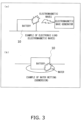
- FIGS. 3a and 3b show examples of damage factors by which the battery 10 is damaged when the internal environment of the battery 10 is changed.
- electromagnetic waves applied to the battery 10 are a damage factor
- moisture entering the interior of the battery 10 is a damage factor.
- FIG. 3a when the battery 10 is irradiated with electromagnetic waves, the CPU 16 of the battery 10 may malfunction and the interior of the battery 10 may be damaged.
- FIG. 3b when the battery 10 is submerged in water, moisture that finds its way into the interior of the battery 10 tends to produce condensation inside the battery 10. Water droplets produced by this condensation can lead to malfunction of the CPU 16 of the battery 10, so this is a factor that can damage the battery 10.
- FIGS. 4a and 4b show examples of damage factors by which the battery 10 is damaged by changing the external environment of the battery 10.
- direct sunlight shining on the battery 10 when the battery is left outdoors, etc. (thermal load) is a damage factor.
- the temperature of the battery 10 rises.
- a high temperature to which the battery 10 is exposed (thermal load) is a damage factor.
- the battery 10 is exposed to a high temperature, the temperature of the battery 10 rises.
- the battery 10 is left at a high temperature for an extended period of time, there is a possibility that the battery 10 will be damaged.
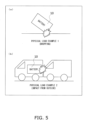
- FIGS. 5a and 5b show examples of physical load as a damage factor.
- an impact to which the battery 10 is subjected is a damage factor.
- FIG. 5a when the user of the system 1 drops the battery 10, there will be a collision between the battery 10 and the ground, and the battery 10 will be subjected to a powerful impact.
- FIG. 5b when a vehicle in which the battery 10 is installed collides with another vehicle, the battery 10 will be subjected indirectly to a powerful impact (physical load).
- the interior of the battery 10 mainly the structural components, supporting members that support these components, etc.
- the cells 12 are cells of a secondary battery. As shown in FIGS. 2A to 2D , the battery 10 comprises a plurality of cells 12. Each cell 12 can be charged with electricity supplied from outside of the battery 10, and can discharge the stored electric power. Switching between charging and discharging of the cells 12 is controlled by the CPU 16.
- the information accumulator 14 stores the damage factor information inputted from the damage factor information acquisition component 11 in the storage component 15. Also, the information accumulator 14 outputs the damage factor information accumulated in the storage component 15 to the information output component 13. The information output component 13 outputs the damage factor information inputted from the information accumulator 14 as output information to an output information acquisition component 211 of the battery management device 20.
- the information accumulator 14 stores damage factor information in the storage component 15.
- the damage factor information includes the internal environment information acquired by the internal environment information acquisition component 11a, the external environment information acquired by the external environment information acquisition component 11b, and the physical load information acquired by the physical load information acquisition component 11c.
- the battery management device 20 comprises a controller 21 (information processing device) and a display component 22.
- the controller 21 comprises the output information acquisition component 211, a damage calculator 212, and a usability determination component 213.
- the components of the controller 21 use the output information outputted from the battery 10 (that is, damage factor information) to calculate the damage degree of the battery 10 and to execute usability determination processing of determining whether or not the battery 10 can continue to be used.
- the controller 21 then causes the display component 22 to display the determination result of the usability determining processing.
- the controller 21 may present the determination result of the usability determining processing to the user by some means other than a display.
- the usability determination processing will be described in detail below.
- the damage calculator 212 and the usability determination component 213 correspond to examples of a physical load information analysis component.
- the output information acquisition component 211 acquires output information from the information output component 13 of the battery 10.
- the output information acquired by the output information acquisition component 211 is the damage factor information acquired by the damage factor information acquisition component 11 of the battery 10, and includes internal environment information, external environment information, and physical load information.
- the output information acquisition component 211 outputs the acquired output information to the damage calculator 212.
- the damage calculator 212 uses the output information inputted from the output information acquisition component 211 to calculate the four types of degree of damage described below (the degree of physical load damage, the degree of temperature load damage, the degree of electronic load damage, and the degree of water wetting damage). Information related to the calculated degree of damage is then outputted to the usability determination component 213. As shown in FIG. 1 , the damage calculator 212 includes a water wetting damage calculator 212a, an electronic load damage calculator 212b, a temperature load damage calculator 212c, and a physical load damage calculator 212d. In a modification example, the damage calculator 212 may calculate some index other than degree of damage, so long as it is one that indicates the usage state of the battery.
- the water wetting damage calculator 212a calculates the degree of water wetting damage, which is the degree of damage to the battery 10 caused by water wetting (see FIG. 3b ). To that end, the water wetting damage calculator 212a selects internal environment information from the output information. As described above, the internal environment information includes the various values sensed by the case internal temperature sensors 30, the cell external temperature sensors 31, the submergence sensors 32, and the electromagnetic wave sensor 33. The water wetting damage calculator 212a uses the values sensed by the submergence sensors 32 to calculate the degree of water wetting damage to the battery 10. Alternatively, when the internal environment information acquisition component 11a is equipped with the humidity sensors 34, the water wetting damage calculator 212a can also use the values sensed by the humidity sensors 34 to calculate the degree of water wetting damage to the battery 10.
- the degree of water wetting damage may correspond to the frequency of malfunction of the CPU 16 of the battery 10.
- the correlation (mathematical model) between the values sensed by the submergence sensors 32 and the frequency of malfunction of the CPU 16 of the battery 10 is learned in advance by experimentation.
- the water wetting damage calculator 212a calculates the degree of water wetting damage (the frequency of malfunction due to water wetting) from the values sensed by the submergence sensors 32, on the basis of the learned correlation.
- the degree of electronic load damage corresponds to the frequency of malfunction of the CPU 16 of the battery 10
- the correlation between the value sensed by the electromagnetic wave sensor 33 and the frequency of occurrence of malfunction of the CPU 16 of the battery 10 is learned in advance by experimentation.
- the electronic load damage calculator 212b calculates the degree of electronic load damage (the frequency of malfunction due to electronic load) from the value sensed by the electromagnetic wave sensor 33 on the basis of the learned correlation.
- the temperature load damage calculator 212c uses the temperature inside the cells 12 (the cell internal temperature) to calculate the degree of damage to the battery 10 due to temperature load (degree of temperature load damage) (see FIGS. 4a and 4b ).
- the degree of temperature load damage corresponds to the frequency of malfunction of the CPU 16 of the battery 10
- the correlation between the cell internal temperature and the frequency of occurrence of malfunction of the CPU 16 of the battery 10 is learned in advance by experimentation.
- the temperature load damage calculator 212c then calculates the degree of temperature load damage (the frequency of malfunction due to temperature load) from the cell internal temperature on the basis of the learned correlation.
- the temperature load damage calculator 212c selects external environment information and internal environment information from the output information.
- the temperature load damage calculator 212c estimates the cell internal temperature from the temperature around the cells 12 (that is, the values sensed by the case internal temperature sensors 30 and the cell external temperature sensors 31 of the internal environment information acquisition component 11a, and the values sensed by the case external temperature sensors 40 of the external environment information acquisition component 11b). The specific method for estimating cell internal temperature will be described in detail below.
- the physical load damage calculator 212d calculates the degree of damage to the battery 10 (mainly the structural components) due to physical load (degree of physical load damage) (see FIGS. 5a and 5b ). To that end, the physical load damage calculator 212d selects physical load information from the output information. The physical load damage calculator 212d uses the values sensed by the acceleration sensor 50, the vibration sensor 51, the strain sensor 52, and the impact sensor 53 of the physical load information acquisition component 11c to calculate the degree of physical load damage.
- the degree of physical load damage may correspond to the amount of separation and breakage of the structural components and support members of the battery 10.
- the correlation between the values sensed by the acceleration sensor 50, the vibration sensor 51, the strain sensor 52, and the impact sensor 53 and the amount of separation and breakage of the structural components and support members of the battery 10 is learned in advance by experimentation.
- the physical load damage calculator 212d then calculates the degree of physical load damage (the amount of separation and breakage due to physical load) from the values sensed by the acceleration sensor 50, the vibration sensor 51, the strain sensor 52, and the impact sensor 53.
- the usability determination component 213 determines whether or not the four kinds of degree of damage calculated by the various components of the damage calculator 212 (the degree of physical load damage, the degree of temperature load damage, the degree of electronic load damage, and the degree of water wetting damage) exceed their respective thresholds. Then, when at least one of the degrees of damage exceeds its threshold, the usability determination component 213 determines that the battery 10 cannot be continued to be used. On the other hand, when all four kinds of degree of damage are at or under their thresholds, the usability determination component 213 determines that it is possible to continue using the battery 10.
- the threshold may be different for each type of degree of damage.
- the above-mentioned threshold may be decided using experimental data showing the correlation between the degree of damage and the damage factors (electronic load, water wetting, electronic load, physical load). The specific method for deciding the thresholds will be described in detail below.
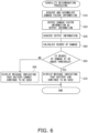
- FIG. 6 is a flowchart showing the flow of the usability determination processing.
- S10 and S20 shown in FIG. 6 are executed in the battery 10 as a preliminary stage to usability determination processing by the controller 21.
- the damage factor information acquisition component 11 acquires damage factor information, and the information accumulator 14 stores the damage factor information in the storage component 15 (S10).
- the information output component 13 outputs the damage factor information as output information (S20).
- the output information acquisition component 211 acquires the output information outputted from the information output component 13, that is, the damage factor information (S30, physical load information acquisition step).
- the various components of the damage calculator 212 use the output information acquired from the output information acquisition component 211 (damage factor information) to calculate the degree of damage to the battery 10 (S40, physical load information analysis step, damage calculation step).
- the usability determination component 213 determines whether or not the degree of damage to the battery 10 calculated by the damage calculator 212 is at or below the threshold (S50, physical load information analysis step, usability determination step). More precisely, the usability determination component 213 determines whether or not each of the four types of degree of damage calculated by the damage calculator 212 is at or below the threshold.
- the usability determination component 213 When degree of damage to the battery 10 (at least one of the four types of degree of damage) is not at or below the threshold (No in S50), the usability determination component 213 causes the display component 22 to display a message of "cannot continue using battery 10" (S60). On the other hand, when the degree of damage to the battery 10 is at or below the threshold (Yes in S50), the usability determination component 213 causes the display component 22 to display a message of "can continue using battery 10" (S70). This concludes the usability determination processing.
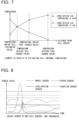
- FIG. 7 is a diagram showing an example of the result of estimating the cell internal temperature with the temperature load damage calculator 212c.
- the case external temperature is sensed by the case external temperature sensors 40
- the case internal temperature is sensed by the case internal temperature sensors 30, and the cell external temperature is sensed by the cell external temperature sensors 31.
- the case external temperature corresponds to the outside air temperature
- the case external temperature when the case external temperature is higher than the case internal temperature and cell external temperature, the outside air temperature is considered to be higher than the cell internal temperature.
- the cell internal temperature is considered less likely than the cell external temperature to be affected by the outside air temperature. Therefore, when the case external temperature is higher than the case internal temperature and the cell external temperature (in FIG. 7 , when the outside air temperature is high), the cell internal temperature is considered to be lower than outside the cell external temperature.
- the temperature load damage calculator 212c estimates the cell internal temperature to be lower than the cell external temperature by extending a curve that passes through the case external temperature, the case internal temperature, and the cell external temperature, as shown in FIG. 7 .
- the temperature load damage calculator 212c estimates the cell internal temperature to be higher than the cell external temperature by extending a curve that passes through the case external temperature, the case internal temperature, and the cell external temperature, as shown in FIG. 7 .
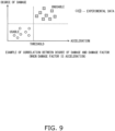
- the threshold used by the usability determination component 213 to make its determination is decided will be described through reference to FIGS. 8 and 9 .
- the damage factors are physical load (acceleration, vibration, strain, and impact).
- the values sensed by the acceleration sensor 50, the vibration sensor 51, the strain sensor 52, and the impact sensor 53 of the physical load information acquisition component 11c are each acquired.
- FIG. 8 is a graph showing examples of the sensed values acquired by the physical load information acquisition component 11c.
- the physical load information acquisition component 11c acquires the sensed values for the acceleration, vibration, strain, and impact to which the battery 10 is subjected.
- the maximum values for the sensed values during the period in which the physical load is applied are specified as the damage factors of the battery 10.
- the degree of damage to the battery 10 is determined. This yields a set of experimental data indicating the relation between the degree of damage and a damage factor of the battery 10 (sensed value for acceleration). It is further determined whether or not a battery 10 whose degree of damage has been determined has been damaged to the extent that it cannot continued to be used.
- FIG. 9 is a graph plotting experimental data indicating the relation between the degree of damage and a damage factor of the battery 10 (sensed value for acceleration).
- the experimental data shown in FIG. 9 includes experimental data for batteries 10 that have been damaged to the extent that they cannot continue to be used (in FIG. 9 , the experimental data marked "unusable"), and experimental data for batteries 10 that have not been damaged to this extent (in FIG. 9 , the experimental data marked "usable”).
- the threshold for acceleration is decided to be a value that can distinguish "unusable” experimental data from "usable” experimental data.
- the threshold of the degree of damage is decided to be a value corresponding to the threshold of acceleration, using the correlation between acceleration and the degree of damage.
- a battery swap system 1001 in Embodiment 2 of the pressure information (hereinafter referred to as the system 1001) will now be described.
- the system 1001 of Embodiment 2 differs from the system 1 in Embodiment 1 in that the system 1001 comprises a usage state determination component 214 (physical load information analysis component). Therefore, the description will focus on this difference. Those components that are the same as in Embodiment 1 will be numbered the same.
- a controller 1021 of a battery management device 1020 in the battery swap system 1001 shown in FIG. 10 further has the usage state determination component 214 in addition to the output information acquisition component 211, the damage calculator 212, and the usability determination component 213.
- the battery management device 1020 determines the usage state of the battery 10 on the basis of the internal environment information, the external environment information, and the physical load information acquired by the output information acquisition component 211.
- the usage state determination component 214 determines the usage state of the battery 10 while it was out on loan.
- the determination of the usage state is, for example, determining whether or not the user used the battery correctly, or whether the user used the battery correctly but the battery was subjected to a damage factor due to an environmental factor, or the battery was subjected to a damage factor due to how the battery was used by the user, etc. More specifically, it can be determined that the battery 10 was subjected to a damage factor because the user left the battery 10 exposed to the sun, or that the battery 10 was subjected to a damage factor because it rose to a temperature not likely to be the outside air temperature.
- the usage state determination component 214 may also determine the usage state on the basis of an index that indicates the usage state calculated by the damage calculator 212.
- the display component 22 displays the determined usage state.
- a display is not the only option here, and the battery management device 1020 may have a communication component, and the determined usage state may be sent to a portable information terminal (smart phone, tablet, etc.) owned by the user.
- a warning or the like may be sent to the portable information terminal of the user.
- the usage state determination component 214 determines the cause for the temperature information on the basis of the sensed values from the sunlight sensors 41 and the sensed values from the case internal temperature sensors 30. More specifically, when the values from the case internal temperature sensors 30 have risen, the usage state determination component 214 can determine from the values sensed by the sunlight sensors 41 whether the increase in the temperature inside the case 17 is "due to the battery 10 being left in sunlight” or is "due to a rise in the outside air temperature.”
- the usage state determination component 214 displays a warning on the display component 22.
- the battery management device 1020 may comprise a communication component, and a warning may be sent to a portable information terminal (smart phone, tablet, etc.) of the user.
- the usage state determination component 214 determines the usage state on the basis of an index indicating the usage state calculated by the damage calculator 212, it means, for example, that sunlight exposure time is converted into an index to calculate the degree of damage, and when the degree of damage due to sunlight exposure time is at or over a specific length of time, the user is determined to be the cause.
- the cell external temperature sensors 31 may be further provided as sensors of the temperature inside the case 17, in addition to the case internal temperature sensors 30. That is, different kinds of sensors may be provided outside and inside the case 17, and a plurality of sensors of the same type may be provided inside the case 17.
- the usage state determination component 214 can determine which region in the battery 10 was submerged, and make an evaluation of the flooding range. For example, when the electronic board housing case 19 has been flooded, but the cell housing case 18 has not been flooded, the electronic board 16a is replaced, but there is a high probability that the cells 12 can be checked and reused. On the other hand, when the cell housing case 18 is flooded, it will be necessary to replace the cells 12.
- the usage state determination component 214 can determine a submerged usage state, which is helpful in repair and replacement.
- the submergence sensors 32 may also be disposed on the outside of the cell housing case 18 and the inside of the case 17.
- degree of damage values may be set for water incursion into the case 17, for water incursion into the electronic board housing case 19, and for water incursion into the cell housing case 18, and the degree of damage calculated.
- the control blocks (particularly the output information acquisition component 211, the damage calculator 212, the usability determination component 213, and the usage state determination component 214) of the battery management devices 20 and 1020 may be realized by a logic circuit formed on an integrated circuit (IC chip), etc. (hardware), or by software using a CPU (central processing unit).
- IC chip integrated circuit
- CPU central processing unit
- the control blocks of the battery management devices 20 and 1020 comprise a CPU that executes the commands of a program (battery management program), which is software for carrying out various functions, a ROM (read only memory) or a storage device (these are referred to as "recording media") in which the above-mentioned program and various kinds of data are recorded so as to be readable by a computer (or CPU), a RAM (random access memory) for developing the program, etc.
- the computer or CPU then reads the program from the recording medium and executes the program, thereby achieving the object of the present invention.
- the recording medium can be a "non-transitory tangible medium,” such as a tape, disk, card, semiconductor memory, or programmable logic circuit.
- the above-mentioned program may be supplied to the computer via any transmission medium capable of transmitting the program (a communication network, a broadcast wave, etc.).
- the present invention can also be realized in the form of a data signal embedded in a carrier wave, in which the program is embodied by electronic transmission.
- the external environment information acquisition component 11b and the internal environment information acquisition component 11a are provided in addition to the physical load information acquisition component 11c, but the external environment information acquisition component 11b and the internal environment information acquisition component 11a need not be provided.
- FIG. 12 is a diagram showing a battery swap system 2001 (hereinafter referred to as the system 2001) in which the external environment information acquisition component 11b and the internal environment information acquisition component 11a are not provided.
- the system 2001 shown in FIG. 12 comprises a battery 2010 and a battery management device 2020.
- the battery 2010 differs from the battery 10 shown in FIG. 1 in that the internal environment information acquisition component 11a and the external environment information acquisition component 11b are not provided, and only the physical load information acquisition component 11c is provided as a damage factor information acquisition component.
- the controller 2021 of the battery management device 2020 differs from the controller 21 of the battery management component 20 shown in FIG. 1 in that the water wetting damage calculator 212a, the electronic load damage calculator 212b and the temperature load damage calculator 212c are not provided, and only the physical load damage calculator 212d is provided as a damage calculator.
- the physical load applied to the battery 2010 is acquired by the physical load information acquisition component 11c and stored in the storage component 15.
- the battery management device 2020 acquires the stored physical load, and the physical load damage calculator 212d calculates the degree of damage to determine whether the battery is usable.
- the cell housing case 18 for housing a plurality of cells and the electronic board housing case 19 for housing the electronic substrate 16a are provided, but one or both may not be provided.
- the battery management device 20 in Embodiment 1 comprises the output information acquisition component 211, the damage calculator 212, and the usability determination component 213, but the usability determination component 213 need not be provided, and the battery management device 20 may function as a battery degree of damage calculation device.
- an electric car or other such vehicle is an example of the power consuming unit in which the batteries 10, 2010, and 3010 loaned out from the systems 1, 1001, 2001, and 3001 are installed.
- vehicles include the above-mentioned electric cars (EVs), electric motorcycles, electric unicycles, electric bicycles, motor-assisted bicycles, and PHVs (plug-in hybrid vehicles).
- the power consuming unit in which the battery is installed is not limited to a move body, and may also be other electrical products that are driven by exchangeable batteries.
- Examples of these electrical products include refrigerators, washing machines, vacuum cleaners, rice cookers, electric kettles, and other such household appliances that run on power from a battery.
- the power consuming unit in which the battery is installed may be a power tool.
- the battery used in the power tool may be charged at a battery station or the like where a plurality of batteries that can be loaned out are charged.
- the pressure information can be utilized in a battery.
Landscapes
- Engineering & Computer Science (AREA)
- Power Engineering (AREA)
- Manufacturing & Machinery (AREA)
- Chemical & Material Sciences (AREA)
- Chemical Kinetics & Catalysis (AREA)
- Electrochemistry (AREA)
- General Chemical & Material Sciences (AREA)
- Mechanical Engineering (AREA)
- Transportation (AREA)
- Sustainable Energy (AREA)
- Sustainable Development (AREA)
- Life Sciences & Earth Sciences (AREA)
- Physics & Mathematics (AREA)
- General Physics & Mathematics (AREA)
- Microelectronics & Electronic Packaging (AREA)
- Secondary Cells (AREA)
- Charge And Discharge Circuits For Batteries Or The Like (AREA)
Claims (12)
- Système (1, 1001, 2001, et 3001) comprenant :une batterie (10, 2010, 3010) comprenant un composant d'acquisition d'informations de charge physique (11c) configuré pour acquérir des informations de charge physique pour la batterie (10, 2010, 3010), etun dispositif de traitement d'informations (21), comprenant :un composant d'acquisition d'informations de sortie (211) configuré pour acquérir les informations de charge physique à partir de la batterie (10, 2010, 3010) ; etun calculateur d'endommagement (212) configuré pour utiliser des informations provenant du composant d'acquisition d'informations de sortie (211) pour calculer un degré d'endommagement de la batterie (10, 2010, 3010),caractérisé en ce que le calculateur d'endommagement (212) a un calculateur d'endommagement de charge physique (212d) configuré pour utiliser les informations de charge physique acquises par le composant d'acquisition d'informations de sortie (211) pour calculer le degré d'endommagement de la batterie (10, 2010, 3010) en raison d'une charge physique sur la base d'une corrélation obtenue précédemment entre les informations de charge physique et une quantité de séparation et de rupture de composants structurels et d'éléments de support de la batterie (10, 2010, 3010).
- Système (1, 1001, 2001, et 3001) selon la revendication 1,
dans lequel le composant d'acquisition d'informations de charge physique (11c) a au moins l'un des éléments suivants : un capteur d'accélération (50) qui détecte des informations d'accélération concernant la batterie (10, 2010, 3010), un capteur de vibration (51) qui acquiert des informations de vibration concernant la batterie (10, 2010, 3010), un capteur de contrainte (52) qui détecte des informations de contrainte concernant la batterie (10, 2010, 3010), un capteur d'impact (53) qui acquiert des informations d'impact concernant la batterie (10, 2010, 3010), un capteur de pression (54) qui acquiert des informations de pression concernant la batterie (10, 2010, 3010), un capteur d'inclinaison (55) qui acquiert des informations d'inclinaison concernant la batterie (10, 2010, 3010), un capteur de position (56) qui acquiert des informations de position concernant la batterie (10, 2010, 3010), et un capteur de vitesse (57) qui détecte des informations de vitesse concernant la batterie (10, 2010, 3010). - Système (1, 1001, 2001, et 3001) selon la revendication 1,
dans lequel la batterie (10, 2010, 3010) comprend en outre un composant de stockage (15) qui stocke les informations de charge physique acquises par le composant d'acquisition d'informations de charge physique (11c). - Système (1, 1001, 2001, et 3001) selon la revendication 1,
dans lequel la batterie (10, 2010, 3010) comprend en outre un composant de communication (13, 3017) qui envoie les informations de charge physique acquises par le composant d'acquisition d'informations de charge physique (11c) au dispositif de traitement d'informations (21). - Système (1, 1001, 2001, et 3001) selon la revendication 1,
dans lequel le dispositif de traitement d'informations (21) est un serveur virtuel en informatique en nuage. - Système (1, 1001, 2001, et 3001) selon la revendication 1,
dans lequel le dispositif de traitement d'informations (21) comprend en outre un composant de détermination d'utilisabilité (213) qui détermine si oui ou non la batterie (10, 2010, 3010) peut être utilisée, sur la base du degré d'endommagement calculé par le calculateur d'endommagement (212). - Système (1, 1001, 2001, et 3001) selon la revendication 1,
dans lequel le dispositif de traitement d'informations (21) comprend en outre un composant de détermination d'état d'utilisation (214) qui utilise des informations acquises par le composant d'acquisition d'informations de sortie (211) pour déterminer un état d'utilisation de la batterie (10, 2010, 3010). - Procédé de gestion de batterie pour gérer une batterie, le procédé de gestion de batterie comprenant :une étape d'acquisition d'informations de charge physique consistant à acquérir des informations de charge physique pour la batterie (10, 2010, 3010) ; etune étape d'analyse d'informations de charge physique consistant à utiliser les informations de charge physique acquises à l'étape d'acquisition d'informations de charge physique pour calculer un degré d'endommagement de la batterie (10, 2010, 3010),dans lequel l'étape d'analyse d'informations de charge physique comprend :
une étape de calcul d'endommagement consistant à utiliser les informations de charge physique pour calculer le degré d'endommagement de la batterie (10, 2010, 3010) en raison d'une charge physique sur la base d'une corrélation obtenue précédemment entre les informations de charge physique et une quantité de séparation et de rupture de composants structurels et d'éléments de support de la batterie (10, 2010, 3010). - Procédé de gestion de batterie selon la revendication 8,
dans lequel l'étape d'analyse d'informations de charge physique comporte :
une étape de détermination d'utilisabilité consistant à déterminer si oui ou non la batterie (10, 2010, 3010) peut être utilisée, sur la base du degré d'endommagement calculé à l'étape de calcul d'endommagement. - Procédé de gestion de batterie selon la revendication 8,
dans lequel l'étape d'analyse d'informations de charge physique comporte :
une étape de détermination d'état d'utilisation consistant à utiliser les informations de charge physique acquises à l'étape d'analyse d'informations de charge physique pour déterminer un état d'utilisation d'une batterie (10, 2010, 3010). - Programme de gestion de batterie pour gérer une batterie, le programme de gestion de batterie comprenant des instructions qui, lorsque le programme de gestion de batterie est exécuté par un ordinateur, amènent l'ordinateur à réaliser le procédé selon l'une des revendications 8 à 10.
- Support d'enregistrement sur lequel est enregistré le programme de gestion de batterie selon la revendication 11, dans lequel le support d'enregistrement est configuré pour être traité par un ordinateur.
Applications Claiming Priority (2)
| Application Number | Priority Date | Filing Date | Title |
|---|---|---|---|
| JP2015049613 | 2015-03-12 | ||
| PCT/JP2016/052143 WO2016143399A1 (fr) | 2015-03-12 | 2016-01-26 | Batterie, système, procédé de gestion de batterie, programme de gestion de batterie, et support d'enregistrement |
Publications (3)
| Publication Number | Publication Date |
|---|---|
| EP3249737A1 EP3249737A1 (fr) | 2017-11-29 |
| EP3249737A4 EP3249737A4 (fr) | 2018-05-02 |
| EP3249737B1 true EP3249737B1 (fr) | 2025-04-30 |
Family
ID=56880236
Family Applications (1)
| Application Number | Title | Priority Date | Filing Date |
|---|---|---|---|
| EP16761371.0A Active EP3249737B1 (fr) | 2015-03-12 | 2016-01-26 | Batterie, système, procédé de gestion de batterie, programme de gestion de batterie, et support d'enregistrement |
Country Status (7)
| Country | Link |
|---|---|
| US (1) | US10355322B2 (fr) |
| EP (1) | EP3249737B1 (fr) |
| JP (1) | JP6489204B2 (fr) |
| MY (1) | MY183538A (fr) |
| PH (1) | PH12017501552B1 (fr) |
| TW (1) | TWI615625B (fr) |
| WO (1) | WO2016143399A1 (fr) |
Families Citing this family (31)
| Publication number | Priority date | Publication date | Assignee | Title |
|---|---|---|---|---|
| CN107632049B (zh) * | 2016-07-19 | 2021-07-13 | 松下知识产权经营株式会社 | 检测系统 |
| DE102016117441A1 (de) * | 2016-09-16 | 2018-03-22 | Dr. Ing. H.C. F. Porsche Aktiengesellschaft | Traktionsbatterie und Fahrzeug mit einer solchen |
| AU2018244050A1 (en) * | 2017-03-30 | 2019-09-26 | Gs Yuasa International Ltd. | Power supply device, server, and power supply device management system |
| KR102323029B1 (ko) * | 2017-08-18 | 2021-11-05 | 주식회사 엘지에너지솔루션 | 자이로센서 및 수분감지센서를 이용한 배터리팩 내 누액 감지 장치 및 감지 방법 |
| KR102248533B1 (ko) | 2017-09-29 | 2021-05-04 | 주식회사 엘지화학 | 컨텍터의 고장률 예측 시스템 및 방법 |
| WO2019172061A1 (fr) * | 2018-03-07 | 2019-09-12 | 株式会社ナイルワークス | Véhicule aérien sans pilote et corps mobile |
| CN116154913A (zh) * | 2018-03-07 | 2023-05-23 | 株式会社尼罗沃克 | 充电器 |
| FR3081393B1 (fr) * | 2018-05-25 | 2022-01-14 | Psa Automobiles Sa | Dispositif de detection de dommage subi par une batterie de vehicule |
| US10914166B2 (en) * | 2018-09-10 | 2021-02-09 | Aps Technology, Inc. | Battery system for downhole drilling tools |
| DE102018219370B3 (de) * | 2018-11-13 | 2019-10-24 | Robert Bosch Gmbh | Verfahren zur Erkennung eines Wassereintritts in einem Gehäuse, elektronische Schaltung zur Durchführung des Verfahrens, Gehäuse mit der elektronischen Schaltung und Fahrzeug mit dem Gehäuse |
| KR102224579B1 (ko) * | 2019-06-17 | 2021-03-09 | ㈜브레이크 더 룰스 | 배터리팩 시스템 |
| KR102738646B1 (ko) * | 2019-07-23 | 2024-12-06 | 주식회사 엘지에너지솔루션 | 차량 배터리 화재 감지 장치 및 감지 방법 |
| JP6871979B2 (ja) * | 2019-08-14 | 2021-05-19 | 本田技研工業株式会社 | 判断装置、判断方法およびプログラム |
| DE102019213054A1 (de) * | 2019-08-29 | 2021-03-04 | Audi Ag | Verfahren zum Ermitteln einer potentiellen Schädigung einer Fahrzeugbatterie sowie Kraftfahrzeug mit einer Fahrzeugbatterie |
| JP7528435B2 (ja) * | 2019-12-19 | 2024-08-06 | 三菱自動車工業株式会社 | 車両用電池パックの安全監視装置 |
| JP2021180543A (ja) * | 2020-05-11 | 2021-11-18 | 本田技研工業株式会社 | バッテリ二次利用判定システムおよびバッテリ二次利用判定方法 |
| JP7503936B2 (ja) * | 2020-06-02 | 2024-06-21 | 本田技研工業株式会社 | バッテリ二次利用判定システムおよびバッテリ二次利用判定方法 |
| DE102020119287A1 (de) | 2020-07-22 | 2022-01-27 | Dr. Ing. H.C. F. Porsche Aktiengesellschaft | Anordnung einer Batterie und Elektrofahrzeug |
| JP7498623B2 (ja) * | 2020-08-20 | 2024-06-12 | 株式会社Subaru | 車両 |
| US12176499B2 (en) * | 2020-10-28 | 2024-12-24 | RePurpose Energy Inc. | Non-destructive battery fire suppression |
| CN214689046U (zh) * | 2020-12-23 | 2021-11-12 | 比亚迪股份有限公司 | 电池包防护系统及车辆 |
| US12230774B2 (en) * | 2021-04-09 | 2025-02-18 | Brunswick Corporation | Marine battery safety system and method |
| KR20230034029A (ko) * | 2021-09-02 | 2023-03-09 | 주식회사 엘지에너지솔루션 | 배터리 데이터 관리 시스템 및 그에 관한 방법 |
| CN114074577B (zh) * | 2021-09-29 | 2024-01-09 | 岚图汽车科技有限公司 | 一种新能源车电池包磕底检测方法和装置 |
| CN114179946B (zh) * | 2022-01-12 | 2022-06-17 | 金华市路骑电动科技有限公司 | 一种电动车数据链路的智能化监测方法及系统 |
| US12351041B1 (en) * | 2022-11-16 | 2025-07-08 | Zoox, Inc. | Impact detection on vehicle underside |
| EP4625750A4 (fr) * | 2022-12-27 | 2026-03-25 | Eve Energy Storage Co Ltd | Procédé et appareil de détermination de politique de protection pour système de stockage d'énergie, et dispositif associé |
| US20250122797A1 (en) * | 2023-10-16 | 2025-04-17 | Baker Hughes Oilfield Operations Llc | Battery safety monitor |
| EP4559718A1 (fr) * | 2023-11-24 | 2025-05-28 | Samsung SDI Co., Ltd. | Procédé de détection et d'évaluation d'un impact mécanique sur un bloc-batterie dans un véhicule au moins partiellement électrique |
| DE102024102984A1 (de) | 2024-02-02 | 2025-08-07 | Audi Aktiengesellschaft | Messanordnung und Verfahren zum Erfassen einer mechanischen Beanspruchung eines Gehäusebauteils eines Gehäuses einer Batterieeinheit |
| CN120473590B (zh) * | 2025-07-15 | 2025-10-17 | 歌尔股份有限公司 | 一种电池保护方法、装置及电子设备 |
Family Cites Families (19)
| Publication number | Priority date | Publication date | Assignee | Title |
|---|---|---|---|---|
| JP2002343074A (ja) | 2001-05-21 | 2002-11-29 | Matsushita Electric Ind Co Ltd | ハードディスクシステム装置およびそのレンタル方法 |
| US7576517B1 (en) * | 2004-11-29 | 2009-08-18 | Data Power Monitoring Corporation | System and method for remote monitoring of battery condition |
| WO2006066251A2 (fr) * | 2004-12-15 | 2006-06-22 | Gaming Enhancements, Inc. | Techniques de generation aleatoire de recompenses au moyen d'une pluralite de valeurs moyennes |
| CN101067644B (zh) | 2007-04-20 | 2010-05-26 | 杭州高特电子设备有限公司 | 蓄电池性能分析专家诊断方法 |
| WO2011034526A1 (fr) | 2009-09-16 | 2011-03-24 | Jonathan Matthew Ross | Procédé et système de gestion de batteries |
| IT1395947B1 (it) * | 2009-10-15 | 2012-11-02 | Meta System Spa | Batteria elettrica per veicoli |
| KR101232786B1 (ko) * | 2009-12-30 | 2013-02-13 | 주식회사 엘지화학 | 배터리 팩 관리 장치 및 방법 |
| JP5343168B2 (ja) * | 2010-06-24 | 2013-11-13 | パナソニック株式会社 | 電池の劣化度を取得するための方法及びそのシステム |
| JP5668424B2 (ja) | 2010-11-16 | 2015-02-12 | ソニー株式会社 | バッテリ装置、バッテリ管理システム、およびバッテリ管理方法 |
| US8751845B2 (en) * | 2011-06-07 | 2014-06-10 | Microsoft Corporation | Estimating and preserving battery life based on usage patterns |
| US20130009531A1 (en) * | 2011-07-07 | 2013-01-10 | Francisco Irace | Universal rail for multi-furniture construction |
| KR20130040575A (ko) * | 2011-10-14 | 2013-04-24 | 삼성에스디아이 주식회사 | 배터리의 고장 검출 장치 및 방법 |
| EP2641783B1 (fr) | 2012-03-20 | 2016-04-20 | Samsung SDI Co., Ltd. | Bloc-batteries et son procédé de commande |
| US9231440B2 (en) | 2012-04-18 | 2016-01-05 | Samsung Sdi Co., Ltd. | Power supply apparatus and controlling method of the same |
| US9267997B2 (en) * | 2012-10-25 | 2016-02-23 | Bayerische Motoren Werke Aktiengesellschaft | Systems and methods to determine the condition of a battery |
| US20140342193A1 (en) * | 2013-05-17 | 2014-11-20 | Tenergy Corporation | Smart battery system |
| JP6102891B2 (ja) * | 2014-11-11 | 2017-03-29 | トヨタ自動車株式会社 | 電池システム |
| MY183607A (en) * | 2015-03-12 | 2021-03-02 | Omron Tateisi Electronics Co | Battery, system, battery damage detection device, battery management method, battey management program, and recording medium |
| CN107250822B (zh) * | 2015-12-03 | 2020-09-01 | 深圳市大疆创新科技有限公司 | 用于确定电池的运行状态的系统和方法 |
-
2016
- 2016-01-26 MY MYPI2017703147A patent/MY183538A/en unknown
- 2016-01-26 JP JP2017504898A patent/JP6489204B2/ja active Active
- 2016-01-26 EP EP16761371.0A patent/EP3249737B1/fr active Active
- 2016-01-26 US US15/554,979 patent/US10355322B2/en active Active
- 2016-01-26 WO PCT/JP2016/052143 patent/WO2016143399A1/fr not_active Ceased
- 2016-02-23 TW TW105105197A patent/TWI615625B/zh active
-
2017
- 2017-08-30 PH PH12017501552A patent/PH12017501552B1/en unknown
Also Published As
| Publication number | Publication date |
|---|---|
| EP3249737A4 (fr) | 2018-05-02 |
| MY183538A (en) | 2021-02-25 |
| TW201632909A (zh) | 2016-09-16 |
| WO2016143399A1 (fr) | 2016-09-15 |
| US10355322B2 (en) | 2019-07-16 |
| JPWO2016143399A1 (ja) | 2017-12-14 |
| JP6489204B2 (ja) | 2019-03-27 |
| TWI615625B (zh) | 2018-02-21 |
| US20180048032A1 (en) | 2018-02-15 |
| PH12017501552A1 (en) | 2018-02-05 |
| PH12017501552B1 (en) | 2021-07-07 |
| EP3249737A1 (fr) | 2017-11-29 |
Similar Documents
| Publication | Publication Date | Title |
|---|---|---|
| EP3249737B1 (fr) | Batterie, système, procédé de gestion de batterie, programme de gestion de batterie, et support d'enregistrement | |
| EP3249736B1 (fr) | Batterie, système, dispositif de détection d'endommagement de batterie, procédé de gestion de batterie, programme de gestion de batterie, et support d'enregistrement | |
| KR102386980B1 (ko) | 배터리의 수명을 추정하는 방법 및 장치 | |
| US20140342193A1 (en) | Smart battery system | |
| KR102805834B1 (ko) | 배터리 관리 방법 및 장치 | |
| US11774504B2 (en) | System and method for battery management | |
| CA2999899C (fr) | Systeme et procedes de mise en service et de maintenance d'un equipement industriel | |
| US20150123669A1 (en) | Battery identification system and method for electronic device, and electronic device | |
| CN116160878B (zh) | 一种换电控制系统及方法、计算机可读介质及电子设备 | |
| Okubanjo et al. | Internet of Batteries: An Integrated System of Battery Health Surveillance System for Electric Vehicles (EVs) | |
| EP4550617A1 (fr) | Appareil et procédé de commande de charge de batterie | |
| US20240402258A1 (en) | Methods, systems, articles of manufacture and apparatus to manage battery outgassing conditions | |
| CN120096386B (zh) | 车辆控制方法、电子设备及车辆 | |
| JP2025021022A (ja) | 判定方法、コンピュータプログラム、判定装置、及び蓄電装置 | |
| WO2025006971A1 (fr) | Détermination de température de batterie et d'emplacement de mesure de température à l'aide de modèles | |
| WO2025198516A1 (fr) | Surveillance et stockage de paramètres liés à une batterie et à un véhicule dans un bloc-batterie remplaçable | |
| KR20250072203A (ko) | 배터리 관리 시스템 및 그 제어 방법 | |
| CN121114774A (zh) | 基于电池数字孪生模型的电池热失控与老化风险预警方法 | |
| KR20250023876A (ko) | 배터리 관리 장치 및 그것의 동작 방법 | |
| CN120352326A (zh) | 确定金属材料的腐蚀速率的方法、装置以及计算机设备 | |
| CN118858986A (zh) | 浸没式电池包的测试方法、装置、计算机设备和存储介质 |
Legal Events
| Date | Code | Title | Description |
|---|---|---|---|
| STAA | Information on the status of an ep patent application or granted ep patent |
Free format text: STATUS: THE INTERNATIONAL PUBLICATION HAS BEEN MADE |
|
| PUAI | Public reference made under article 153(3) epc to a published international application that has entered the european phase |
Free format text: ORIGINAL CODE: 0009012 |
|
| STAA | Information on the status of an ep patent application or granted ep patent |
Free format text: STATUS: REQUEST FOR EXAMINATION WAS MADE |
|
| 17P | Request for examination filed |
Effective date: 20170824 |
|
| AK | Designated contracting states |
Kind code of ref document: A1 Designated state(s): AL AT BE BG CH CY CZ DE DK EE ES FI FR GB GR HR HU IE IS IT LI LT LU LV MC MK MT NL NO PL PT RO RS SE SI SK SM TR |
|
| AX | Request for extension of the european patent |
Extension state: BA ME |
|
| A4 | Supplementary search report drawn up and despatched |
Effective date: 20180406 |
|
| RIC1 | Information provided on ipc code assigned before grant |
Ipc: G01L 5/00 20060101ALI20180329BHEP Ipc: G01R 31/36 20060101ALI20180329BHEP Ipc: H01M 10/42 20060101ALI20180329BHEP Ipc: H01M 2/10 20060101ALI20180329BHEP Ipc: H01M 10/48 20060101AFI20180329BHEP Ipc: B60L 11/18 20060101ALI20180329BHEP |
|
| DAV | Request for validation of the european patent (deleted) | ||
| DAX | Request for extension of the european patent (deleted) | ||
| STAA | Information on the status of an ep patent application or granted ep patent |
Free format text: STATUS: EXAMINATION IS IN PROGRESS |
|
| 17Q | First examination report despatched |
Effective date: 20210719 |
|
| GRAP | Despatch of communication of intention to grant a patent |
Free format text: ORIGINAL CODE: EPIDOSNIGR1 |
|
| STAA | Information on the status of an ep patent application or granted ep patent |
Free format text: STATUS: GRANT OF PATENT IS INTENDED |
|
| RIC1 | Information provided on ipc code assigned before grant |
Ipc: G01L 5/00 20060101ALI20241111BHEP Ipc: G01R 31/36 20060101ALI20241111BHEP Ipc: H01M 10/42 20060101ALI20241111BHEP Ipc: H01M 10/48 20060101AFI20241111BHEP |
|
| INTG | Intention to grant announced |
Effective date: 20241209 |
|
| GRAS | Grant fee paid |
Free format text: ORIGINAL CODE: EPIDOSNIGR3 |
|
| GRAA | (expected) grant |
Free format text: ORIGINAL CODE: 0009210 |
|
| STAA | Information on the status of an ep patent application or granted ep patent |
Free format text: STATUS: THE PATENT HAS BEEN GRANTED |
|
| AK | Designated contracting states |
Kind code of ref document: B1 Designated state(s): AL AT BE BG CH CY CZ DE DK EE ES FI FR GB GR HR HU IE IS IT LI LT LU LV MC MK MT NL NO PL PT RO RS SE SI SK SM TR |
|
| REG | Reference to a national code |
Ref country code: CH Ref legal event code: EP Ref country code: GB Ref legal event code: FG4D |
|
| REG | Reference to a national code |
Ref country code: IE Ref legal event code: FG4D |
|
| REG | Reference to a national code |
Ref country code: DE Ref legal event code: R096 Ref document number: 602016092075 Country of ref document: DE |
|
| REG | Reference to a national code |
Ref country code: NL Ref legal event code: MP Effective date: 20250430 |
|
| REG | Reference to a national code |
Ref country code: AT Ref legal event code: MK05 Ref document number: 1790951 Country of ref document: AT Kind code of ref document: T Effective date: 20250430 |
|
| PG25 | Lapsed in a contracting state [announced via postgrant information from national office to epo] |
Ref country code: PT Free format text: LAPSE BECAUSE OF FAILURE TO SUBMIT A TRANSLATION OF THE DESCRIPTION OR TO PAY THE FEE WITHIN THE PRESCRIBED TIME-LIMIT Effective date: 20250901 Ref country code: FI Free format text: LAPSE BECAUSE OF FAILURE TO SUBMIT A TRANSLATION OF THE DESCRIPTION OR TO PAY THE FEE WITHIN THE PRESCRIBED TIME-LIMIT Effective date: 20250430 Ref country code: ES Free format text: LAPSE BECAUSE OF FAILURE TO SUBMIT A TRANSLATION OF THE DESCRIPTION OR TO PAY THE FEE WITHIN THE PRESCRIBED TIME-LIMIT Effective date: 20250430 |
|
| REG | Reference to a national code |
Ref country code: LT Ref legal event code: MG9D |
|
| PG25 | Lapsed in a contracting state [announced via postgrant information from national office to epo] |
Ref country code: NO Free format text: LAPSE BECAUSE OF FAILURE TO SUBMIT A TRANSLATION OF THE DESCRIPTION OR TO PAY THE FEE WITHIN THE PRESCRIBED TIME-LIMIT Effective date: 20250730 Ref country code: GR Free format text: LAPSE BECAUSE OF FAILURE TO SUBMIT A TRANSLATION OF THE DESCRIPTION OR TO PAY THE FEE WITHIN THE PRESCRIBED TIME-LIMIT Effective date: 20250731 |
|
| PG25 | Lapsed in a contracting state [announced via postgrant information from national office to epo] |
Ref country code: PL Free format text: LAPSE BECAUSE OF FAILURE TO SUBMIT A TRANSLATION OF THE DESCRIPTION OR TO PAY THE FEE WITHIN THE PRESCRIBED TIME-LIMIT Effective date: 20250430 Ref country code: NL Free format text: LAPSE BECAUSE OF FAILURE TO SUBMIT A TRANSLATION OF THE DESCRIPTION OR TO PAY THE FEE WITHIN THE PRESCRIBED TIME-LIMIT Effective date: 20250430 |
|
| PG25 | Lapsed in a contracting state [announced via postgrant information from national office to epo] |
Ref country code: BG Free format text: LAPSE BECAUSE OF FAILURE TO SUBMIT A TRANSLATION OF THE DESCRIPTION OR TO PAY THE FEE WITHIN THE PRESCRIBED TIME-LIMIT Effective date: 20250430 |
|
| PG25 | Lapsed in a contracting state [announced via postgrant information from national office to epo] |
Ref country code: HR Free format text: LAPSE BECAUSE OF FAILURE TO SUBMIT A TRANSLATION OF THE DESCRIPTION OR TO PAY THE FEE WITHIN THE PRESCRIBED TIME-LIMIT Effective date: 20250430 |
|
| PG25 | Lapsed in a contracting state [announced via postgrant information from national office to epo] |
Ref country code: AT Free format text: LAPSE BECAUSE OF FAILURE TO SUBMIT A TRANSLATION OF THE DESCRIPTION OR TO PAY THE FEE WITHIN THE PRESCRIBED TIME-LIMIT Effective date: 20250430 |
|
| PG25 | Lapsed in a contracting state [announced via postgrant information from national office to epo] |
Ref country code: RS Free format text: LAPSE BECAUSE OF FAILURE TO SUBMIT A TRANSLATION OF THE DESCRIPTION OR TO PAY THE FEE WITHIN THE PRESCRIBED TIME-LIMIT Effective date: 20250731 |
|
| PG25 | Lapsed in a contracting state [announced via postgrant information from national office to epo] |
Ref country code: IS Free format text: LAPSE BECAUSE OF FAILURE TO SUBMIT A TRANSLATION OF THE DESCRIPTION OR TO PAY THE FEE WITHIN THE PRESCRIBED TIME-LIMIT Effective date: 20250830 |
|
| PG25 | Lapsed in a contracting state [announced via postgrant information from national office to epo] |
Ref country code: LV Free format text: LAPSE BECAUSE OF FAILURE TO SUBMIT A TRANSLATION OF THE DESCRIPTION OR TO PAY THE FEE WITHIN THE PRESCRIBED TIME-LIMIT Effective date: 20250430 |
|
| PG25 | Lapsed in a contracting state [announced via postgrant information from national office to epo] |
Ref country code: SM Free format text: LAPSE BECAUSE OF FAILURE TO SUBMIT A TRANSLATION OF THE DESCRIPTION OR TO PAY THE FEE WITHIN THE PRESCRIBED TIME-LIMIT Effective date: 20250430 Ref country code: DK Free format text: LAPSE BECAUSE OF FAILURE TO SUBMIT A TRANSLATION OF THE DESCRIPTION OR TO PAY THE FEE WITHIN THE PRESCRIBED TIME-LIMIT Effective date: 20250430 |
|
| PG25 | Lapsed in a contracting state [announced via postgrant information from national office to epo] |
Ref country code: CZ Free format text: LAPSE BECAUSE OF FAILURE TO SUBMIT A TRANSLATION OF THE DESCRIPTION OR TO PAY THE FEE WITHIN THE PRESCRIBED TIME-LIMIT Effective date: 20250430 |
|
| PG25 | Lapsed in a contracting state [announced via postgrant information from national office to epo] |
Ref country code: EE Free format text: LAPSE BECAUSE OF FAILURE TO SUBMIT A TRANSLATION OF THE DESCRIPTION OR TO PAY THE FEE WITHIN THE PRESCRIBED TIME-LIMIT Effective date: 20250430 |
|
| PG25 | Lapsed in a contracting state [announced via postgrant information from national office to epo] |
Ref country code: SK Free format text: LAPSE BECAUSE OF FAILURE TO SUBMIT A TRANSLATION OF THE DESCRIPTION OR TO PAY THE FEE WITHIN THE PRESCRIBED TIME-LIMIT Effective date: 20250430 Ref country code: RO Free format text: LAPSE BECAUSE OF FAILURE TO SUBMIT A TRANSLATION OF THE DESCRIPTION OR TO PAY THE FEE WITHIN THE PRESCRIBED TIME-LIMIT Effective date: 20250430 |
|
| PG25 | Lapsed in a contracting state [announced via postgrant information from national office to epo] |
Ref country code: IT Free format text: LAPSE BECAUSE OF FAILURE TO SUBMIT A TRANSLATION OF THE DESCRIPTION OR TO PAY THE FEE WITHIN THE PRESCRIBED TIME-LIMIT Effective date: 20250430 |
|
| REG | Reference to a national code |
Ref country code: DE Ref legal event code: R097 Ref document number: 602016092075 Country of ref document: DE |
|
| PLBE | No opposition filed within time limit |
Free format text: ORIGINAL CODE: 0009261 |
|
| STAA | Information on the status of an ep patent application or granted ep patent |
Free format text: STATUS: NO OPPOSITION FILED WITHIN TIME LIMIT |
|
| REG | Reference to a national code |
Ref country code: CH Ref legal event code: L10 Free format text: ST27 STATUS EVENT CODE: U-0-0-L10-L00 (AS PROVIDED BY THE NATIONAL OFFICE) Effective date: 20260311 |
|
| 26N | No opposition filed |
Effective date: 20260202 |