EP3249788A1 - Elektrisch umlaufende maschine mit einem wicklungskopf - Google Patents
Elektrisch umlaufende maschine mit einem wicklungskopf Download PDFInfo
- Publication number
- EP3249788A1 EP3249788A1 EP17168132.3A EP17168132A EP3249788A1 EP 3249788 A1 EP3249788 A1 EP 3249788A1 EP 17168132 A EP17168132 A EP 17168132A EP 3249788 A1 EP3249788 A1 EP 3249788A1
- Authority
- EP
- European Patent Office
- Prior art keywords
- machine
- bun
- axis
- axial
- stator
- Prior art date
- Legal status (The legal status is an assumption and is not a legal conclusion. Google has not performed a legal analysis and makes no representation as to the accuracy of the status listed.)
- Granted
Links
Images



Classifications
-
- H—ELECTRICITY
- H02—GENERATION; CONVERSION OR DISTRIBUTION OF ELECTRIC POWER
- H02K—DYNAMO-ELECTRIC MACHINES
- H02K15/00—Processes or apparatus specially adapted for manufacturing, assembling, maintaining or repairing of dynamo-electric machines
- H02K15/20—Shaping or compacting conductors or winding heads after the installation of the winding in the cores or machines; Applying fastening means on winding heads
- H02K15/24—Shaping or compacting winding heads
-
- H—ELECTRICITY
- H02—GENERATION; CONVERSION OR DISTRIBUTION OF ELECTRIC POWER
- H02K—DYNAMO-ELECTRIC MACHINES
- H02K15/00—Processes or apparatus specially adapted for manufacturing, assembling, maintaining or repairing of dynamo-electric machines
- H02K15/08—Forming windings by laying conductors into or around core parts
- H02K15/085—Forming windings by laying conductors into or around core parts by laying conductors into slotted stators
-
- H—ELECTRICITY
- H02—GENERATION; CONVERSION OR DISTRIBUTION OF ELECTRIC POWER
- H02K—DYNAMO-ELECTRIC MACHINES
- H02K15/00—Processes or apparatus specially adapted for manufacturing, assembling, maintaining or repairing of dynamo-electric machines
- H02K15/20—Shaping or compacting conductors or winding heads after the installation of the winding in the cores or machines; Applying fastening means on winding heads
-
- H—ELECTRICITY
- H02—GENERATION; CONVERSION OR DISTRIBUTION OF ELECTRIC POWER
- H02K—DYNAMO-ELECTRIC MACHINES
- H02K19/00—Synchronous motors or generators
-
- H—ELECTRICITY
- H02—GENERATION; CONVERSION OR DISTRIBUTION OF ELECTRIC POWER
- H02K—DYNAMO-ELECTRIC MACHINES
- H02K3/00—Details of windings
- H02K3/04—Windings characterised by the conductor shape, form or construction, e.g. with bar conductors
- H02K3/24—Windings characterised by the conductor shape, form or construction, e.g. with bar conductors with channels or ducts for cooling medium between the conductors
-
- H—ELECTRICITY
- H02—GENERATION; CONVERSION OR DISTRIBUTION OF ELECTRIC POWER
- H02K—DYNAMO-ELECTRIC MACHINES
- H02K3/00—Details of windings
- H02K3/04—Windings characterised by the conductor shape, form or construction, e.g. with bar conductors
- H02K3/28—Layout of windings or of connections between windings
-
- H—ELECTRICITY
- H02—GENERATION; CONVERSION OR DISTRIBUTION OF ELECTRIC POWER
- H02K—DYNAMO-ELECTRIC MACHINES
- H02K3/00—Details of windings
- H02K3/46—Fastening of windings on the stator or rotor structure
- H02K3/50—Fastening of winding heads, equalising connectors, or connections thereto
-
- H—ELECTRICITY
- H02—GENERATION; CONVERSION OR DISTRIBUTION OF ELECTRIC POWER
- H02K—DYNAMO-ELECTRIC MACHINES
- H02K9/00—Arrangements for cooling or ventilating
-
- H—ELECTRICITY
- H02—GENERATION; CONVERSION OR DISTRIBUTION OF ELECTRIC POWER
- H02K—DYNAMO-ELECTRIC MACHINES
- H02K9/00—Arrangements for cooling or ventilating
- H02K9/02—Arrangements for cooling or ventilating by ambient air flowing through the machine
- H02K9/04—Arrangements for cooling or ventilating by ambient air flowing through the machine having means for generating a flow of cooling medium
- H02K9/06—Arrangements for cooling or ventilating by ambient air flowing through the machine having means for generating a flow of cooling medium with fans or impellers driven by the machine shaft
-
- H—ELECTRICITY
- H02—GENERATION; CONVERSION OR DISTRIBUTION OF ELECTRIC POWER
- H02K—DYNAMO-ELECTRIC MACHINES
- H02K2213/00—Specific aspects, not otherwise provided for and not covered by codes H02K2201/00 - H02K2211/00
- H02K2213/03—Machines characterised by numerical values, ranges, mathematical expressions or similar information
Definitions
- the present invention relates to a rotating electric machine provided with a bun with an improved shape, the machine being intended to be installed in a motor vehicle to operate with a heat engine or to propel the motor vehicle.
- the invention also relates to a method of constructing such a rotating electrical machine.
- the rotating electrical machines comprise two coaxial parts, namely a rotor and a stator surrounding the body of the rotor.
- alternator with internal ventilation of the polyphase type for a motor vehicle with a heat engine operating in alternator mode.
- alternator can also be reversible and consist of an alternator-starter also operating in electric motor mode, in particular to start the engine of the vehicle as described in the document FR A 2,745,445 to ensure the propulsion of the motor vehicle.
- the machine 100 When the machine 100 operates in alternator mode, it transforms mechanical energy into electrical energy like any alternator. When the machine operates in electric motor mode, especially in starter mode to start the engine of the vehicle, it transforms electrical energy into mechanical energy.
- This machine 100 essentially comprises a housing 1 and, inside thereof, a rotor 2 integral in rotation with a central shaft 3, called a rotor shaft, and a stator 50 of annular shape, which surrounds the rotor 2 with presence of an air gap and which comprises a body 4 in the form of a pack of sheets with notches, for example of the semi-closed type, for mounting a stator winding 5 forming on either side of the stator body 4, at each axial end thereof, a front bun 51 and a rear bun 53 which project axially.
- This winding 5 comprises for example a set of three-phase star or delta windings, the outputs of which are connected to a rectifier bridge, partially visible at 52, comprising rectifying elements such as diodes or MOSFET transistors, especially when the machine consists of an alternator-starter.
- the windings of the winding 5 are obtained by means of a continuous, electrically conductive wire coated with an electrically insulating layer, such as enamel, and mounted in the respective notches of the body 4 of the stator 50 via insulators. notches (not visible).
- the winding 5 comprises two sets of three-phase windings to form a device for composite stator windings, the windings being shifted by thirty electric degrees as described for example in the documents US-A1-2002 / 0175589 , and FR-A-2784248 .
- two rectifier bridges are provided and all combinations of three-phase star and / or delta windings are possible.
- the stator winding is of the pentaphase type.
- the alternator is of the polyphase type and the rectifier bridge or bridges make it possible, in particular, to rectify the alternating current produced in the windings of the stator 50 into a direct current, in particular for charging the battery of the motor vehicle and supplying the loads and electrical consumers of the on-board network of the motor vehicle.
- the rotor 2 of annular shape is made in the example shown in the form of a claw rotor, as described for example in the documents US-A1 -2002/01 75589 , comprising two pole wheels 7,8 here axially juxtaposed and each having an annular transverse flange provided at its outer periphery with claws 9.
- Each claw 9 has a rooting section of transverse orientation in the plane of the flange concerned.
- This rooting section is extended at its outer periphery by an orientation tooth overall axial with presence of a chamfer between the tooth and the rooting section
- An annular gap exists between the outer peripheral face of the teeth of the claws 9 and the inner periphery of the body 4 of the stator 50.
- the teeth are generally trapezoidal or triangular.
- the teeth of a pole wheel 7, 8 are directed axially towards the flange of the other pole wheel 8, 7; the tooth of a wheel 7, 8 penetrating the space between two adjacent teeth of the other wheel 7, 8 so that the teeth of the wheels 7, 8 are interleaved.
- the document EP 051 259 See the document EP 051 259 .
- An excitation winding 10 is implanted axially between the flanges of the wheels 7, 8. It is carried by a rotor portion 2 in the form of a cylindrical annular core coaxial with the shaft 3.
- the core of the figure 1 consists of two axially distinct sections each of which is realized integrally with an associated 7.8 pole wheel.
- the central core consists of a single piece and is distinct from the pole wheels 7, 8 which are arranged axially on either side of the core.
- the winding 10 is thus implanted in the space delimited radially by the claws 9 of the wheels 7,8 and the central core.
- the wheels 7, 8 and the core are preferably of ferromagnetic material and are traversed coaxially by the rotor shaft 3 also made of ferromagnetic material. These wheels 7, 8 are integral with the shaft 3.
- each wheel 7, 8 comprises a central bore which passes axially through the flange and extends the bore of the part of the core concerned.
- the shaft 3 has knurled portions (not referenced) and is force-fitted into the aforementioned bores of the core and the wheels 7, 8 so that it cuts grooves through its knurled portions.
- the shaft 3 is thus integral in rotation and axially wheels, a spacer, not referenced, being interposed between the wheel 7 and a bearing 19 described below.
- the axis of the shaft 3 constitutes the X axis of the machine.
- the winding wire 10 is wound on a support of electrically insulating material (not shown) mounted, preferably by force, on the outer periphery of the core.
- the wheels 7, 8 and the core are magnetized and the rotor 2 becomes an inductor rotor with the formation of magnetic poles at the claws 9 wheels 7, 8.
- This inductor rotor 2 creates an alternating induced current in the stator 50 induced when the shaft 3 rotates.
- the shaft 3 of the rotor 2 carries at its front end a movement transmission member 12, here a pulley 12 belonging to a device for transmitting movements through at least one belt (not shown) between the alternator and the engine of the motor vehicle.
- This shaft carries at its rear end slip rings 13 connected by wire bonds (not shown) to the ends of the excitation winding 10 of the rotor 2.
- the pulley 12 is replaced by a gear and the transmission device is chain and / or gear.
- Brushes belong to a brush holder shown generally at reference 14 and they are arranged so as to rub on the slip rings 13, to supply the winding 10 with electrical current.
- the brush holder 14 is connected to a voltage regulator (not shown).
- the casing 1 in which are placed the rotor 2 and the stator 50 is here in two parts, namely a front flange 16 adjacent to the pulley 12 and a rear flange 17 carrying the brush holder 14 and most often the bridge or bridges rectifiers and the voltage regulator.
- the flanges 16, 17 of annular shape, for example based on aluminum, are hollow in shape and each bear a central ball bearing respectively 19 and 20 for the rotational mounting of the shaft 3 of the rotor 2.
- the flanges are assembled together using tie rods or screws as visible for example in the figure 1 of the document EP 0515 259 supra.
- the casing 1 of the machine 100 includes the front flange 16 also called front bearing and the rear flange 17 also rear bearing.
- an elastic system for filtering vibrations is provided at the outer periphery of the body 4 of the stator, in the form of a sheet package, with a flat gasket 40 at the front and at the rear of the pads 41 a flexible resin and thermo conductive being interposed between the front flange and the stator body to remove the heat.
- stator is fixedly carried by the casing 1, while the rotor 2 is carried centrally rotatably by the casing 1 via the bearings 19, 20.
- the housing is in three parts, the flanges 16, 17 being disposed on either side of a central portion carrying the stator body.
- the flanges are assembled to the intermediate portion for example by screwing.
- the alternator also comprises means for cooling it.
- the flanges 16, 17 are perforated to allow cooling of the alternator by air circulation and the rotor 2 carries at least at one of its axial ends a fan for ensuring the circulation of air.
- a first fan 23 is provided on the front end face of the rotor 2 and a second fan 24, on the rear face of the rotor 12.
- Each fan 23, 24 is of annular shape and is provided with a plurality of blades 26 and is fixed on the outer radial faces of the flanges of the wheels 7,8.
- the fans are for example metallic and are obtained with their blades 26 by cutting and folding.
- the fans 23, 24 are for example centrifugal or helico-centrifugal type.
- the air is sucked by openings 60 of the front flange surrounding the pulley 12 at the front of the flange and is mainly ejected centrifugally by the blades 26 and passes into the space between the front bun 51 and the front flange 16 to cool the front bun and finally exit through openings 61 on the outer radial periphery of the flange before.
- the rear flange 17 also has a plurality of air inlet and outlet ports.
- the brush holder 14 and the voltage regulator, integral with the flange 17, are capped by a cover 70, integral with the rear flange 17 being fixed here on the latter, in a known manner, by snapping on studs 71 integral with the flange back.
- This cover 70 also has air intake orifices, not visible at the figure 1 .
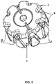
- the figure 2 illustrates a claw rotor according to the state of the art. It includes a pair of nested wheels 7 and 8. The wheels 7 and 8 comprise claws 9. Optionally, the rotor 2 comprises inter-polar magnets 38. The rotor 2 illustrated in FIG. figure 2 includes 8 pairs of poles.
- This machine is satisfactory, however, it may be desirable to further improve it especially by reducing the noise it generates when it is in operation, driven by the engine or in the case of an alternator-starter when it operates in motor mode.
- the front bun totally masks in a direction perpendicular to the axis X the blades of the axial surface located on the front side of the machine.
- the front bun plays the role of sound shield vis-a-vis the noise generated by the blades of the axial surface located on the front side of the machine. It is thus possible that these noises are attenuated by the bun.
- This is a solution that reduces noise without compromising the performance of the machine including cooling and the current it delivers if it operates in alternator mode.
- the blades of the axial surface located on the front side of the machine allow centrifugal ejection of the cooling air.
- the method further comprises, after the winding step, a step of shifting in an axial direction of the winding with respect to the stator body so that the front axial chignon completely masks the blades of the axial surface located front side of the machine in a direction perpendicular to the X axis.
- a method is thus proposed which is easy to implement and insertable in the current manufacturing steps.
- the figure 3 illustrates a rotating electric machine 100 provided with an X axis according to the invention.
- This machine is different from the machine illustrated on the figure 1 in particular in that the bun 51 completely masks the blades 26 of the fan 23.
- the machine 100 comprises a first part formed in particular by the front flange 16 and a second part formed in particular by the rear flange 17. These two parts are named front and rear depending on their position relative to the axis X. More precisely the front part is located on the side of the pulley 12 while the rear part is located on the side of the electric cover 70.
- the rotor 2 is of X axis and comprises two axial end surfaces 81 and 82 which are provided with fan blades 26, 24 allowing a flow cooling air for example by centrifugal ejection.
- the two surfaces 81 and 82 are respectively located on the side of the front part and the side of the rear part of the machine.
- the two axial surfaces 81 and 82 are each located in one of the two planes perpendicular to the axis X which define the rotor 2.
- the stator 50 comprises a coil 5 installed in the notches forming a front bun 51 which extends from an axial end of the stator body 4 towards the front part of the machine and a rear bun 53 which extends from from another axial end of the stator body towards the rear part of the machine 1.
- the front bun 51 completely masks the blades 26 of the axial surface 81 located on the front side of the machine in a direction perpendicular to the X axis.
- the level along the X axis of the front bun 51 is greater than or equal to the level along the X axis of the masked blades 26.
- a plane 85 is defined passing between the two wheels 7 and 8 of the rotor 2 represented by a straight line dotted on the figure 3 .
- a plane 83 is defined comprising the axial end of the front bun 51, said axial end corresponding to the point of the bun 51 farthest from the stator body 4 along the X axis. This plane is represented by a dotted line on the figure 3 .
- a plane 84 is defined comprising the axial end of the blades 26, said axial end corresponding to the point of the blades 26 farthest from the wheel 7 along the axis X. This plane is represented by a dotted line on the figure 3 .
- the level of the bun 51 is understood to mean the distance between the plane 83 and the plane 85, and in the same way, by the level of the blades 26 of the axial surface 81, is meant the distance between the plane 84 and the plane 85.
- the difference between the level of the bun 51 and the level of the blades 26 of the axial surface 81 is between 0 and 1 mm.
- the stator body 4 is for example formed by a bundle of plates having a height Hs defined as the distance between two planes perpendicular to the axis X delimiting the stator body.
- the front bun 51 and rear 53 each have a height defined as the distance between the plane perpendicular to the X axis comprising the point of the bun furthest from the stator body and one of the two planes perpendicular to the X axis delimiting the body of stator.
- the height Ha of the front bun 51 is 23mm
- the height Hb of the rear bun 53 is 22mm
- the height Hs of the sheet package forming the body 4 of the stator 50 is 35mm.
- the height of the front bun with respect to the rear bun so that the ratio R1 is between 1 and 5%, for example between 2 and 4%.
- This difference in level between the front bun 51 and the rear bun 53 can be obtained by means of an offset of the winding 5 with respect to the stator body.
- the winding 5 installed in the slots is offset from the stator body so that the front bun 51 completely masks the blades 26 of the axial surface 81 located on the front side of the machine while the blades 26 of the axial surface located 82 on the rear side of the machine protrude axially from the rear bun 53.
- the front bun will thus play the role of a shield of the noise of the centrifugal air flows, these air flows allowing by circulation of an air flow on the front bun 51 including the cooling of the machine.
- FIG. 3 the flow of cooling air into the front part of the machine.
- This flow comprises an aspiration of the cooling air through the openings 60 of the flange, its centrifugal ejection by the blades 26, then its passage in the space between the front bun 51 and the front flange 16 to cool the front bun, and finally its exit through openings 61.
- the rear bun 53 is less critical for the noise, because the flows are more erratic due in particular to the presence of the electronic part to be cooled and axial flows that make the centrifugal flows less preponderant. Thus, even if, due to the forward shift of the winding 5, the rear bun 53 masks less the blades 26 of the axial surface 82 located on the rear side of the machine, a reduction of the overall noise is obtained.
- certain harmonics related to the geometry of the rotor are preponderant.
- the number of rotor blades on the axial surface 81 located on the front side the number of rotor blades on the axial surface 8 located on the rear side, the number of pairs of poles. It is intended according to the invention to prevent these numbers from being identical, which would lead to a summation of several harmonics of the same order.
- the perceived loudness is greater than with several noise components having different harmonic orders.
- the rotor 2 comprises a number of pairs of poles different from that of the number of blades 26 of the two axial surfaces 81, 82 of ends respectively.
- the number of pole pairs is 8, while the number of blades is 11 or 13.
- the cooling performance of the machine and especially the front bun 51 is related to the cooling air flow blown by the blades 26 of the axial surface located on the front side of the machine.
- the noise generated by these flows is directly related to the speed of the air.
- the front bun 51 has a shape allowing a reduced air ejection speed for a given ejection rate.
- the figure 4 illustrates a detail of the stator 50 according to the invention. It comprises a stator body 4, a winding 5 installed in notches 93, the winding forming the front bun 51 and the rear bun 53.
- the buns comprise son 90 provided with two axial portions 91 extending along the X axis and a transverse portion 92 extending in a plane perpendicular to the X axis, the front bun 51 forming spacings 94 located between the transverse portions and the stator body 4.
- spacings 94 allow passage of air. Thus, one obtains a surface of the flux which increases and thus a reduction of the flow velocity and the noise for a given flow rate.
- the buns include groups of threads that extend between two notches.
- the son of these groups of son comprise the two axial portions 91 and the transverse portion 92.
- these groups of son have substantially the shape of a rectangle.
- the shape of each of these groups may be triangular or conical, which makes it possible to substantially increase the surface area of the flow of the centrifugal flows in order to limit their speed.
- a compromise must be respected because the role sound shield of the bun can be limited by these forms.
- the bun 51 comprises a head having a conical shape, the head being the part of the bun furthest away axially from the stator body 4.
- the head comprises the axial end of the front bun 51.
- the figure 5 represents the stator 50 according to one embodiment.
- the sound produced by a rotating electrical machine comprises many components each having an order. Each of these components has a sound level related to the geometry of the elements of the rotor and / or the stator.
- the noise comprises a component of order 12 which is related to the number of claws of the rotor and the number of stator bunches.
- the noise also includes an order 11 component which is related to the number of rotor fan blades. Noise is a sound level that is the sum of the sound levels of all these components.
- the figure 6 shows two groups of curves 112 and 113.
- the group 112 represents a sound level of the rotating electrical machines as illustrated in FIG. figure 1 while the group 113 represents a sound level of rotating electrical machines as illustrated in FIG. figure 3 .
- the axis 110 represents the speed of rotation in revolutions per minute.
- This axis 110 comprises a lower limit 117 of a value of 9000 revolutions / minute for example and an upper limit 118 with a value of 18 000 revolutions per minute for example.
- the axis 110 is graduated from 1000 to 1000 and includes secondary graduations of 500 to 500.
- the axis 110 further comprises an intermediate value 119 of 13204 revolutions / minute.
- Axis 111 represents the value of the sound level expressed in dBW (A).
- This axis 111 comprises a lower terminal 115 of a value of 85 dBW (A) for example and an upper limit 116 of a value of 105 dBW (A) for example.
- the axis 111 is graduated from 1 to 1.
- a value expressed in dBW (A) indicates a decibel evaluation of a sound level with the weighting A of the IEC 61672-1 standard. This weighting is established to take into account the average ear sensitivity of people with normal hearing for each frequency band. This weighting thus makes it possible to illustrate a noise level felt by a user of the motor vehicle.
- the sound level of the groups of curves 112 and 113 illustrated on the figure 6 is that of the component of order 11 also called harmonic 11.
- the group of curves 113 comprises 3 curves each representing the sound level of the harmonic of order 11 as a function of the speed of rotation of the rotor for an electric machine known to those skilled in the art.
- the group of curves 112 comprises 3 curves representing the sound level of the harmonic of order 11 as a function of the speed of rotation of the rotor for electrical machines in which the front bun 51 masks the fan blades of the axial surface of end 81 located on the front side of the machine by means of a winding offset 5 towards the front of the machine so that the height Ha is 1 mm higher than the height Hb.
- the figure 7 illustrates a machine according to a second embodiment of the invention.
- This machine comprises two flow windows 101 and 102 of the cooling air which are defined between the casing 1 and the front bun 51, the thickness of the casing 1 being reduced at these windows 101, 102 to allow an increase of said window.
- the flow velocity can be reduced and thus the noise reduced.
- the thickness of the front flange can be reduced by 1 mm.
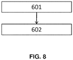
- the figure 8 illustrates a method of manufacturing a rotating electric machine 1 as illustrated in FIGS. figures 3 and 7 .
- this electric machine is provided with an X axis, and comprises a front portion 16 and a rear portion 17 with respect to the X axis.
- the machine further comprises an X-axis rotor 2 comprising two end axial surfaces 81, 82 which are provided with fan blades 26 allowing a flow of cooling air for example by centrifugal ejection. These two axial surfaces 81, 82 are located respectively on the side of the front part and the side of the rear part 17 of the machine 1.
- the machine further comprises a stator 50 which comprises a stator body 4 having notches 93 and surrounding said rotor 2.
- the invention is applicable to rotors having blades 26 greater or equal to the axial surface 81 located on the front side of the machine than at the axial surface 82 located on the rear side of the machine.
- the invention is also applicable to rotors having blades 26 higher at the axial surface 82 located on the rear side of the machine than at the axial surface 81 located on the front side of the machine.
- the invention is applicable to all types of fan blades, whether centrifugal or mixed.
Landscapes
- Engineering & Computer Science (AREA)
- Power Engineering (AREA)
- Manufacturing & Machinery (AREA)
- Motor Or Generator Cooling System (AREA)
- Windings For Motors And Generators (AREA)
Priority Applications (1)
| Application Number | Priority Date | Filing Date | Title |
|---|---|---|---|
| EP21187088.6A EP3920383A1 (de) | 2016-05-25 | 2017-04-26 | Elektrisch umlaufende maschine, die mit einem wicklungskopf ausgestattet ist |
Applications Claiming Priority (1)
| Application Number | Priority Date | Filing Date | Title |
|---|---|---|---|
| FR1654707A FR3051988B1 (fr) | 2016-05-25 | 2016-05-25 | Machine electrique tournante munie d'un chignon |
Related Child Applications (1)
| Application Number | Title | Priority Date | Filing Date |
|---|---|---|---|
| EP21187088.6A Division EP3920383A1 (de) | 2016-05-25 | 2017-04-26 | Elektrisch umlaufende maschine, die mit einem wicklungskopf ausgestattet ist |
Publications (2)
| Publication Number | Publication Date |
|---|---|
| EP3249788A1 true EP3249788A1 (de) | 2017-11-29 |
| EP3249788B1 EP3249788B1 (de) | 2021-07-28 |
Family
ID=56611406
Family Applications (2)
| Application Number | Title | Priority Date | Filing Date |
|---|---|---|---|
| EP21187088.6A Pending EP3920383A1 (de) | 2016-05-25 | 2017-04-26 | Elektrisch umlaufende maschine, die mit einem wicklungskopf ausgestattet ist |
| EP17168132.3A Active EP3249788B1 (de) | 2016-05-25 | 2017-04-26 | Rotierende elektrische maschine mit einem wicklungskopf |
Family Applications Before (1)
| Application Number | Title | Priority Date | Filing Date |
|---|---|---|---|
| EP21187088.6A Pending EP3920383A1 (de) | 2016-05-25 | 2017-04-26 | Elektrisch umlaufende maschine, die mit einem wicklungskopf ausgestattet ist |
Country Status (5)
| Country | Link |
|---|---|
| US (1) | US10447122B2 (de) |
| EP (2) | EP3920383A1 (de) |
| JP (1) | JP2017212874A (de) |
| CN (1) | CN107437860B (de) |
| FR (1) | FR3051988B1 (de) |
Cited By (1)
| Publication number | Priority date | Publication date | Assignee | Title |
|---|---|---|---|---|
| EP3282562B1 (de) * | 2016-08-11 | 2020-10-28 | ALSTOM Transport Technologies | Elektromotor, der eine schalldämpfungsvorrichtung umfasst |
Citations (10)
| Publication number | Priority date | Publication date | Assignee | Title |
|---|---|---|---|---|
| EP0515259A1 (de) | 1991-05-21 | 1992-11-25 | Valeo Equipements Electriques Moteur | Drehstromgenerator für Kraftfahrzeuge bzw. Kraftwagen |
| US5250864A (en) * | 1991-07-19 | 1993-10-05 | Mitsubishi Denki K.K. | AC generator for vehicles |
| EP0671801A2 (de) * | 1994-03-11 | 1995-09-13 | Nippondenso Co., Ltd. | Wechselstromgenerator für Kraftfahrzeuge |
| FR2745445A1 (fr) | 1996-02-28 | 1997-08-29 | Valeo Electronique | Alternateur de vehicule automobile utilise comme generateur et comme moteur electrique pour le demarrage du moteur a combustion interne du vehicule |
| EP0917278A2 (de) * | 1997-09-26 | 1999-05-19 | Denso Corporation | Fahrzeugsgenerator |
| FR2784248A1 (fr) | 1998-10-02 | 2000-04-07 | Valeo Equip Electr Moteur | Alternateur pour vehicule avec rattrapage de jeu sur les aimants interpolaires |
| EP0998011A1 (de) * | 1998-10-29 | 2000-05-03 | Valeo Equipements Electriques Moteur | Drehende elektrische Maschine mit verringerten Kuhlluftgeräuschen, i.e. ein Fahrzeuggenerator, und Herstellungsverfahren seines Stators |
| JP2000358348A (ja) * | 1999-04-14 | 2000-12-26 | Denso Corp | 車両用交流発電機 |
| US20020175589A1 (en) | 2001-05-28 | 2002-11-28 | Mitsubishi Denki Kabushiki Kaisha | Automotive alternator |
| EP2873139A1 (de) * | 2012-07-11 | 2015-05-20 | Valeo Equipements Electriques Moteur | Elektrische drehmaschine für ein kraftfahrzeug |
Family Cites Families (21)
| Publication number | Priority date | Publication date | Assignee | Title |
|---|---|---|---|---|
| US1479636A (en) * | 1919-09-15 | 1924-01-01 | John B Wiard | Dynamo-electric machine |
| US2074067A (en) * | 1935-10-14 | 1937-03-16 | Master Electric Co | Ventilated splashproof motor housing |
| US2193408A (en) * | 1937-03-10 | 1940-03-12 | Allis Chalmers Mfg Co | Dynamo-electric machine |
| US2286750A (en) * | 1940-07-26 | 1942-06-16 | Gen Electric | Dynamoelectric machine |
| US2436930A (en) * | 1944-01-17 | 1948-03-02 | Foote Bros Gear And Machine Co | Motor reducer unit |
| US2571907A (en) * | 1946-08-15 | 1951-10-16 | Westinghouse Electric Corp | Convertible motor |
| US2545855A (en) * | 1948-08-21 | 1951-03-20 | Us Electrical Motors Inc | Ventilated dynamoelectric machinery |
| US2608677A (en) * | 1950-10-20 | 1952-08-26 | Gen Electric | Dynamoelectric machine ventilation |
| US2716195A (en) * | 1952-12-26 | 1955-08-23 | Fairbanks Morse & Co | Ventilation of electric machines |
| US2836741A (en) * | 1954-09-09 | 1958-05-27 | Siemens Ag | Dynamo-electric amplifier |
| US3020427A (en) * | 1960-03-14 | 1962-02-06 | Gen Electric | Ventilation of dynamoelectric machine drive units |
| US3250926A (en) * | 1963-04-11 | 1966-05-10 | Emerson Electric Co | Ventilated motor |
| US3761748A (en) * | 1972-07-10 | 1973-09-25 | Gen Electric | Dynamoelectric machine having end shields for improved ventilation |
| JPS5310801A (en) * | 1976-07-19 | 1978-01-31 | Hitachi Ltd | Rotary machine |
| JPS60187241A (ja) * | 1984-03-07 | 1985-09-24 | Hitachi Ltd | 車輛用交流発電機 |
| US4859889A (en) * | 1988-06-28 | 1989-08-22 | General Electric Company | Dynamoelectric machine |
| JPH04190655A (ja) * | 1990-11-21 | 1992-07-09 | Hitachi Ltd | 車両用交流発電機 |
| US5757094A (en) * | 1997-03-28 | 1998-05-26 | General Electric Canada Inc. | Ventilation system for an AC machine having overhanging salient poles with juxtaposed shrouds |
| JP3438606B2 (ja) * | 1997-09-26 | 2003-08-18 | 株式会社デンソー | 車両用交流発電機 |
| US6313559B1 (en) * | 1999-04-14 | 2001-11-06 | Denso Corporation | Stator arrangement of rotary electric machine |
| FR2819350B1 (fr) * | 2001-01-05 | 2003-04-11 | Valeo Equip Electr Moteur | Machine tournante perfectionnee pour vehicules automobiles |
-
2016
- 2016-05-25 FR FR1654707A patent/FR3051988B1/fr active Active
-
2017
- 2017-04-26 EP EP21187088.6A patent/EP3920383A1/de active Pending
- 2017-04-26 EP EP17168132.3A patent/EP3249788B1/de active Active
- 2017-05-19 US US15/600,053 patent/US10447122B2/en active Active
- 2017-05-24 JP JP2017102568A patent/JP2017212874A/ja active Pending
- 2017-05-25 CN CN201710377469.0A patent/CN107437860B/zh active Active
Patent Citations (10)
| Publication number | Priority date | Publication date | Assignee | Title |
|---|---|---|---|---|
| EP0515259A1 (de) | 1991-05-21 | 1992-11-25 | Valeo Equipements Electriques Moteur | Drehstromgenerator für Kraftfahrzeuge bzw. Kraftwagen |
| US5250864A (en) * | 1991-07-19 | 1993-10-05 | Mitsubishi Denki K.K. | AC generator for vehicles |
| EP0671801A2 (de) * | 1994-03-11 | 1995-09-13 | Nippondenso Co., Ltd. | Wechselstromgenerator für Kraftfahrzeuge |
| FR2745445A1 (fr) | 1996-02-28 | 1997-08-29 | Valeo Electronique | Alternateur de vehicule automobile utilise comme generateur et comme moteur electrique pour le demarrage du moteur a combustion interne du vehicule |
| EP0917278A2 (de) * | 1997-09-26 | 1999-05-19 | Denso Corporation | Fahrzeugsgenerator |
| FR2784248A1 (fr) | 1998-10-02 | 2000-04-07 | Valeo Equip Electr Moteur | Alternateur pour vehicule avec rattrapage de jeu sur les aimants interpolaires |
| EP0998011A1 (de) * | 1998-10-29 | 2000-05-03 | Valeo Equipements Electriques Moteur | Drehende elektrische Maschine mit verringerten Kuhlluftgeräuschen, i.e. ein Fahrzeuggenerator, und Herstellungsverfahren seines Stators |
| JP2000358348A (ja) * | 1999-04-14 | 2000-12-26 | Denso Corp | 車両用交流発電機 |
| US20020175589A1 (en) | 2001-05-28 | 2002-11-28 | Mitsubishi Denki Kabushiki Kaisha | Automotive alternator |
| EP2873139A1 (de) * | 2012-07-11 | 2015-05-20 | Valeo Equipements Electriques Moteur | Elektrische drehmaschine für ein kraftfahrzeug |
Cited By (1)
| Publication number | Priority date | Publication date | Assignee | Title |
|---|---|---|---|---|
| EP3282562B1 (de) * | 2016-08-11 | 2020-10-28 | ALSTOM Transport Technologies | Elektromotor, der eine schalldämpfungsvorrichtung umfasst |
Also Published As
| Publication number | Publication date |
|---|---|
| US10447122B2 (en) | 2019-10-15 |
| EP3920383A1 (de) | 2021-12-08 |
| JP2017212874A (ja) | 2017-11-30 |
| CN107437860A (zh) | 2017-12-05 |
| US20170346357A1 (en) | 2017-11-30 |
| EP3249788B1 (de) | 2021-07-28 |
| FR3051988B1 (fr) | 2019-10-11 |
| CN107437860B (zh) | 2020-08-21 |
| FR3051988A1 (fr) | 2017-12-01 |
Similar Documents
| Publication | Publication Date | Title |
|---|---|---|
| EP2826133B1 (de) | Anordnung von endkappen, die lüfterschaufeln zur erzeugung einer axialen luftströmung in einem rotor umfassen | |
| EP1929611B1 (de) | Lüftungssystem für elektrische drehmaschinen mit einer kühlvorrichtung mit erzwungenem flüssigkeitsfluss und elektrische drehmaschine damit | |
| EP1293026B1 (de) | Ventilator für drehende elektrische maschine | |
| EP3005534A1 (de) | Elektrische maschine mit einem dämpfer für mechanischen widerstand gegen schwingungsbelastung und entsprechender dämpfer | |
| EP2826135B1 (de) | Anordnung von flanschen des rotors einer drehenden elektrischen maschine mit asymmetrischen öffnungen zur förderung einer axialen luftströmung im inneren des rotors sowie der dazu zugehörige rotor | |
| EP3104501A1 (de) | Rotor für elektrisch umlaufende maschine | |
| WO2017207929A1 (fr) | Machine electrique tournante munie d'un roulement avec une bague intérieure ayant une surface d'extrémité axiale pourvue de micro-picots | |
| EP2795765A1 (de) | Schenkelpolläufer mit einer vorrichtung zum isolieren der wicklungen und zugehörige vorrichtung zur isolierung der wicklungen | |
| EP1661230A1 (de) | Elektrische polyphasen-drehmaschine, wie zum beispiel eine lichtmaschine oder ein alterno-anlasser insbesondere für ein kraftfahrzeug | |
| EP2860847B1 (de) | Bewickelter Stator mit optimierter Nutenfüllung, und entsprechende elektrische Maschine | |
| FR3051988B1 (fr) | Machine electrique tournante munie d'un chignon | |
| WO2008000992A2 (fr) | Stator pour machine electrique tournante et une telle machine | |
| WO2017093635A1 (fr) | Rotor a griffes de machine electrique tournante muni d'au moins un chanfrein realise dans un bord de fuite d'une griffe | |
| WO2021099023A1 (fr) | Rotor pour machine électrique tournante | |
| WO2018020188A1 (fr) | Machine electrique tournante munie d'un stator avec un bobinage epingle | |
| WO2017093636A1 (fr) | Rotor a griffes de machine electrique tournante muni de griffes a chanfrein de forme courbe | |
| WO2017093634A1 (fr) | Rotor a griffes de machine electrique tournante a performances magnetiques ameliorees | |
| FR3058846B1 (fr) | Machine electrique tournante comprenant un arbre de rotor et un roulement | |
| FR3103330A1 (fr) | Rotor pour machine électrique tournante | |
| EP2795766A2 (de) | Schenkelpolläufer mit flanschen zum halten der kontaktierungsdrähte der wicklungen und zugehörige halteflansche | |
| WO2017093640A1 (fr) | Rotor a griffes de machine electrique tournante muni d'au moins un chanfrein realise dans une griffe | |
| FR3059171A1 (fr) | Ensemble poulie pour machine electrique tournante | |
| FR3054740A1 (fr) | Corps de stator pour machine electrique tournante | |
| EP3059834A1 (de) | Spule für rotor einer elektrisch umlaufenden maschine, und entsprechender rotor | |
| WO2018002522A1 (fr) | Rotor a double excitation pour machine electrique tournante |
Legal Events
| Date | Code | Title | Description |
|---|---|---|---|
| PUAI | Public reference made under article 153(3) epc to a published international application that has entered the european phase |
Free format text: ORIGINAL CODE: 0009012 |
|
| STAA | Information on the status of an ep patent application or granted ep patent |
Free format text: STATUS: REQUEST FOR EXAMINATION WAS MADE |
|
| 17P | Request for examination filed |
Effective date: 20170426 |
|
| AK | Designated contracting states |
Kind code of ref document: A1 Designated state(s): AL AT BE BG CH CY CZ DE DK EE ES FI FR GB GR HR HU IE IS IT LI LT LU LV MC MK MT NL NO PL PT RO RS SE SI SK SM TR |
|
| AX | Request for extension of the european patent |
Extension state: BA ME |
|
| STAA | Information on the status of an ep patent application or granted ep patent |
Free format text: STATUS: EXAMINATION IS IN PROGRESS |
|
| 17Q | First examination report despatched |
Effective date: 20181017 |
|
| GRAP | Despatch of communication of intention to grant a patent |
Free format text: ORIGINAL CODE: EPIDOSNIGR1 |
|
| STAA | Information on the status of an ep patent application or granted ep patent |
Free format text: STATUS: GRANT OF PATENT IS INTENDED |
|
| INTG | Intention to grant announced |
Effective date: 20210218 |
|
| GRAS | Grant fee paid |
Free format text: ORIGINAL CODE: EPIDOSNIGR3 |
|
| GRAA | (expected) grant |
Free format text: ORIGINAL CODE: 0009210 |
|
| STAA | Information on the status of an ep patent application or granted ep patent |
Free format text: STATUS: THE PATENT HAS BEEN GRANTED |
|
| AK | Designated contracting states |
Kind code of ref document: B1 Designated state(s): AL AT BE BG CH CY CZ DE DK EE ES FI FR GB GR HR HU IE IS IT LI LT LU LV MC MK MT NL NO PL PT RO RS SE SI SK SM TR |
|
| REG | Reference to a national code |
Ref country code: GB Ref legal event code: FG4D Free format text: NOT ENGLISH |
|
| REG | Reference to a national code |
Ref country code: CH Ref legal event code: EP |
|
| REG | Reference to a national code |
Ref country code: AT Ref legal event code: REF Ref document number: 1415603 Country of ref document: AT Kind code of ref document: T Effective date: 20210815 |
|
| REG | Reference to a national code |
Ref country code: IE Ref legal event code: FG4D Free format text: LANGUAGE OF EP DOCUMENT: FRENCH |
|
| REG | Reference to a national code |
Ref country code: DE Ref legal event code: R096 Ref document number: 602017042778 Country of ref document: DE |
|
| REG | Reference to a national code |
Ref country code: LT Ref legal event code: MG9D |
|
| REG | Reference to a national code |
Ref country code: NL Ref legal event code: MP Effective date: 20210728 |
|
| REG | Reference to a national code |
Ref country code: AT Ref legal event code: MK05 Ref document number: 1415603 Country of ref document: AT Kind code of ref document: T Effective date: 20210728 |
|
| PG25 | Lapsed in a contracting state [announced via postgrant information from national office to epo] |
Ref country code: RS Free format text: LAPSE BECAUSE OF FAILURE TO SUBMIT A TRANSLATION OF THE DESCRIPTION OR TO PAY THE FEE WITHIN THE PRESCRIBED TIME-LIMIT Effective date: 20210728 Ref country code: SE Free format text: LAPSE BECAUSE OF FAILURE TO SUBMIT A TRANSLATION OF THE DESCRIPTION OR TO PAY THE FEE WITHIN THE PRESCRIBED TIME-LIMIT Effective date: 20210728 Ref country code: NO Free format text: LAPSE BECAUSE OF FAILURE TO SUBMIT A TRANSLATION OF THE DESCRIPTION OR TO PAY THE FEE WITHIN THE PRESCRIBED TIME-LIMIT Effective date: 20211028 Ref country code: NL Free format text: LAPSE BECAUSE OF FAILURE TO SUBMIT A TRANSLATION OF THE DESCRIPTION OR TO PAY THE FEE WITHIN THE PRESCRIBED TIME-LIMIT Effective date: 20210728 Ref country code: PT Free format text: LAPSE BECAUSE OF FAILURE TO SUBMIT A TRANSLATION OF THE DESCRIPTION OR TO PAY THE FEE WITHIN THE PRESCRIBED TIME-LIMIT Effective date: 20211129 Ref country code: HR Free format text: LAPSE BECAUSE OF FAILURE TO SUBMIT A TRANSLATION OF THE DESCRIPTION OR TO PAY THE FEE WITHIN THE PRESCRIBED TIME-LIMIT Effective date: 20210728 Ref country code: FI Free format text: LAPSE BECAUSE OF FAILURE TO SUBMIT A TRANSLATION OF THE DESCRIPTION OR TO PAY THE FEE WITHIN THE PRESCRIBED TIME-LIMIT Effective date: 20210728 Ref country code: ES Free format text: LAPSE BECAUSE OF FAILURE TO SUBMIT A TRANSLATION OF THE DESCRIPTION OR TO PAY THE FEE WITHIN THE PRESCRIBED TIME-LIMIT Effective date: 20210728 Ref country code: BG Free format text: LAPSE BECAUSE OF FAILURE TO SUBMIT A TRANSLATION OF THE DESCRIPTION OR TO PAY THE FEE WITHIN THE PRESCRIBED TIME-LIMIT Effective date: 20211028 Ref country code: AT Free format text: LAPSE BECAUSE OF FAILURE TO SUBMIT A TRANSLATION OF THE DESCRIPTION OR TO PAY THE FEE WITHIN THE PRESCRIBED TIME-LIMIT Effective date: 20210728 Ref country code: LT Free format text: LAPSE BECAUSE OF FAILURE TO SUBMIT A TRANSLATION OF THE DESCRIPTION OR TO PAY THE FEE WITHIN THE PRESCRIBED TIME-LIMIT Effective date: 20210728 |
|
| PG25 | Lapsed in a contracting state [announced via postgrant information from national office to epo] |
Ref country code: PL Free format text: LAPSE BECAUSE OF FAILURE TO SUBMIT A TRANSLATION OF THE DESCRIPTION OR TO PAY THE FEE WITHIN THE PRESCRIBED TIME-LIMIT Effective date: 20210728 Ref country code: LV Free format text: LAPSE BECAUSE OF FAILURE TO SUBMIT A TRANSLATION OF THE DESCRIPTION OR TO PAY THE FEE WITHIN THE PRESCRIBED TIME-LIMIT Effective date: 20210728 Ref country code: GR Free format text: LAPSE BECAUSE OF FAILURE TO SUBMIT A TRANSLATION OF THE DESCRIPTION OR TO PAY THE FEE WITHIN THE PRESCRIBED TIME-LIMIT Effective date: 20211029 |
|
| PG25 | Lapsed in a contracting state [announced via postgrant information from national office to epo] |
Ref country code: DK Free format text: LAPSE BECAUSE OF FAILURE TO SUBMIT A TRANSLATION OF THE DESCRIPTION OR TO PAY THE FEE WITHIN THE PRESCRIBED TIME-LIMIT Effective date: 20210728 |
|
| REG | Reference to a national code |
Ref country code: DE Ref legal event code: R097 Ref document number: 602017042778 Country of ref document: DE |
|
| PG25 | Lapsed in a contracting state [announced via postgrant information from national office to epo] |
Ref country code: SM Free format text: LAPSE BECAUSE OF FAILURE TO SUBMIT A TRANSLATION OF THE DESCRIPTION OR TO PAY THE FEE WITHIN THE PRESCRIBED TIME-LIMIT Effective date: 20210728 Ref country code: SK Free format text: LAPSE BECAUSE OF FAILURE TO SUBMIT A TRANSLATION OF THE DESCRIPTION OR TO PAY THE FEE WITHIN THE PRESCRIBED TIME-LIMIT Effective date: 20210728 Ref country code: RO Free format text: LAPSE BECAUSE OF FAILURE TO SUBMIT A TRANSLATION OF THE DESCRIPTION OR TO PAY THE FEE WITHIN THE PRESCRIBED TIME-LIMIT Effective date: 20210728 Ref country code: EE Free format text: LAPSE BECAUSE OF FAILURE TO SUBMIT A TRANSLATION OF THE DESCRIPTION OR TO PAY THE FEE WITHIN THE PRESCRIBED TIME-LIMIT Effective date: 20210728 Ref country code: CZ Free format text: LAPSE BECAUSE OF FAILURE TO SUBMIT A TRANSLATION OF THE DESCRIPTION OR TO PAY THE FEE WITHIN THE PRESCRIBED TIME-LIMIT Effective date: 20210728 Ref country code: AL Free format text: LAPSE BECAUSE OF FAILURE TO SUBMIT A TRANSLATION OF THE DESCRIPTION OR TO PAY THE FEE WITHIN THE PRESCRIBED TIME-LIMIT Effective date: 20210728 |
|
| PLBE | No opposition filed within time limit |
Free format text: ORIGINAL CODE: 0009261 |
|
| STAA | Information on the status of an ep patent application or granted ep patent |
Free format text: STATUS: NO OPPOSITION FILED WITHIN TIME LIMIT |
|
| 26N | No opposition filed |
Effective date: 20220429 |
|
| PG25 | Lapsed in a contracting state [announced via postgrant information from national office to epo] |
Ref country code: IT Free format text: LAPSE BECAUSE OF FAILURE TO SUBMIT A TRANSLATION OF THE DESCRIPTION OR TO PAY THE FEE WITHIN THE PRESCRIBED TIME-LIMIT Effective date: 20210728 |
|
| REG | Reference to a national code |
Ref country code: CH Ref legal event code: PL |
|
| GBPC | Gb: european patent ceased through non-payment of renewal fee |
Effective date: 20220426 |
|
| REG | Reference to a national code |
Ref country code: BE Ref legal event code: MM Effective date: 20220430 |
|
| PG25 | Lapsed in a contracting state [announced via postgrant information from national office to epo] |
Ref country code: MC Free format text: LAPSE BECAUSE OF FAILURE TO SUBMIT A TRANSLATION OF THE DESCRIPTION OR TO PAY THE FEE WITHIN THE PRESCRIBED TIME-LIMIT Effective date: 20210728 Ref country code: LU Free format text: LAPSE BECAUSE OF NON-PAYMENT OF DUE FEES Effective date: 20220426 Ref country code: LI Free format text: LAPSE BECAUSE OF NON-PAYMENT OF DUE FEES Effective date: 20220430 Ref country code: GB Free format text: LAPSE BECAUSE OF NON-PAYMENT OF DUE FEES Effective date: 20220426 Ref country code: CH Free format text: LAPSE BECAUSE OF NON-PAYMENT OF DUE FEES Effective date: 20220430 |
|
| PG25 | Lapsed in a contracting state [announced via postgrant information from national office to epo] |
Ref country code: BE Free format text: LAPSE BECAUSE OF NON-PAYMENT OF DUE FEES Effective date: 20220430 |
|
| PG25 | Lapsed in a contracting state [announced via postgrant information from national office to epo] |
Ref country code: IE Free format text: LAPSE BECAUSE OF NON-PAYMENT OF DUE FEES Effective date: 20220426 |
|
| P01 | Opt-out of the competence of the unified patent court (upc) registered |
Effective date: 20230528 |
|
| PG25 | Lapsed in a contracting state [announced via postgrant information from national office to epo] |
Ref country code: HU Free format text: LAPSE BECAUSE OF FAILURE TO SUBMIT A TRANSLATION OF THE DESCRIPTION OR TO PAY THE FEE WITHIN THE PRESCRIBED TIME-LIMIT; INVALID AB INITIO Effective date: 20170426 |
|
| PG25 | Lapsed in a contracting state [announced via postgrant information from national office to epo] |
Ref country code: MK Free format text: LAPSE BECAUSE OF FAILURE TO SUBMIT A TRANSLATION OF THE DESCRIPTION OR TO PAY THE FEE WITHIN THE PRESCRIBED TIME-LIMIT Effective date: 20210728 Ref country code: CY Free format text: LAPSE BECAUSE OF FAILURE TO SUBMIT A TRANSLATION OF THE DESCRIPTION OR TO PAY THE FEE WITHIN THE PRESCRIBED TIME-LIMIT Effective date: 20210728 |
|
| PG25 | Lapsed in a contracting state [announced via postgrant information from national office to epo] |
Ref country code: TR Free format text: LAPSE BECAUSE OF FAILURE TO SUBMIT A TRANSLATION OF THE DESCRIPTION OR TO PAY THE FEE WITHIN THE PRESCRIBED TIME-LIMIT Effective date: 20210728 |
|
| PG25 | Lapsed in a contracting state [announced via postgrant information from national office to epo] |
Ref country code: MT Free format text: LAPSE BECAUSE OF FAILURE TO SUBMIT A TRANSLATION OF THE DESCRIPTION OR TO PAY THE FEE WITHIN THE PRESCRIBED TIME-LIMIT Effective date: 20210728 |
|
| PGFP | Annual fee paid to national office [announced via postgrant information from national office to epo] |
Ref country code: DE Payment date: 20250411 Year of fee payment: 9 |
|
| PGFP | Annual fee paid to national office [announced via postgrant information from national office to epo] |
Ref country code: FR Payment date: 20250429 Year of fee payment: 9 |