EP3249793A1 - Kraftfahrzeugstarter mit einem ständer mit verbesserter magnetischer leistung - Google Patents
Kraftfahrzeugstarter mit einem ständer mit verbesserter magnetischer leistung Download PDFInfo
- Publication number
- EP3249793A1 EP3249793A1 EP17172228.3A EP17172228A EP3249793A1 EP 3249793 A1 EP3249793 A1 EP 3249793A1 EP 17172228 A EP17172228 A EP 17172228A EP 3249793 A1 EP3249793 A1 EP 3249793A1
- Authority
- EP
- European Patent Office
- Prior art keywords
- winding
- starter according
- stator
- cores
- strip
- Prior art date
- Legal status (The legal status is an assumption and is not a legal conclusion. Google has not performed a legal analysis and makes no representation as to the accuracy of the status listed.)
- Withdrawn
Links
- 239000007858 starting material Substances 0.000 title claims abstract description 30
- 238000004804 winding Methods 0.000 claims abstract description 45
- 238000002485 combustion reaction Methods 0.000 claims abstract description 4
- XAGFODPZIPBFFR-UHFFFAOYSA-N aluminium Chemical compound [Al] XAGFODPZIPBFFR-UHFFFAOYSA-N 0.000 claims description 6
- 229910052782 aluminium Inorganic materials 0.000 claims description 6
- 238000007373 indentation Methods 0.000 claims description 6
- 239000012777 electrically insulating material Substances 0.000 claims description 5
- RYGMFSIKBFXOCR-UHFFFAOYSA-N Copper Chemical compound [Cu] RYGMFSIKBFXOCR-UHFFFAOYSA-N 0.000 claims description 3
- 229910052802 copper Inorganic materials 0.000 claims description 3
- 239000010949 copper Substances 0.000 claims description 3
- 210000003298 dental enamel Anatomy 0.000 claims description 3
- 230000004323 axial length Effects 0.000 description 2
- 239000004020 conductor Substances 0.000 description 2
- 230000003247 decreasing effect Effects 0.000 description 2
- 230000018109 developmental process Effects 0.000 description 2
- 239000011810 insulating material Substances 0.000 description 2
- 238000000034 method Methods 0.000 description 2
- 241000287107 Passer Species 0.000 description 1
- 239000011149 active material Substances 0.000 description 1
- 238000007743 anodising Methods 0.000 description 1
- 210000000078 claw Anatomy 0.000 description 1
- 238000001816 cooling Methods 0.000 description 1
- 239000000463 material Substances 0.000 description 1
- 238000004080 punching Methods 0.000 description 1
Images

Classifications
-
- H—ELECTRICITY
- H02—GENERATION; CONVERSION OR DISTRIBUTION OF ELECTRIC POWER
- H02K—DYNAMO-ELECTRIC MACHINES
- H02K23/00—DC commutator motors or generators having mechanical commutator; Universal AC/DC commutator motors
- H02K23/02—DC commutator motors or generators having mechanical commutator; Universal AC/DC commutator motors characterised by arrangement for exciting
-
- H—ELECTRICITY
- H02—GENERATION; CONVERSION OR DISTRIBUTION OF ELECTRIC POWER
- H02K—DYNAMO-ELECTRIC MACHINES
- H02K1/00—Details of the magnetic circuit
- H02K1/06—Details of the magnetic circuit characterised by the shape, form or construction
- H02K1/12—Stationary parts of the magnetic circuit
- H02K1/14—Stator cores with salient poles
- H02K1/146—Stator cores with salient poles consisting of a generally annular yoke with salient poles
- H02K1/148—Sectional cores
-
- H—ELECTRICITY
- H02—GENERATION; CONVERSION OR DISTRIBUTION OF ELECTRIC POWER
- H02K—DYNAMO-ELECTRIC MACHINES
- H02K3/00—Details of windings
- H02K3/04—Windings characterised by the conductor shape, form or construction, e.g. with bar conductors
- H02K3/18—Windings for salient poles
Definitions
- the present invention relates to a motor vehicle starter with a stator with improved magnetic performance.
- Motor vehicle starters having a stator, or inductor, and a rotor, or induced, separated from the stator via an air gap.
- the rotor body consists of a bundle of plates having longitudinal slots in which are inserted the winding son constituted for example by pin-shaped conductors.
- the rotor is further provided with a manifold comprising a plurality of contact pieces electrically connected to the winding wires.
- the stator comprises a body provided with a yoke and polar masses regularly distributed angularly on the inner face of the yoke.
- coils wound around the polar masses are intended to be traversed by a current so as to create an alternation of north poles and south poles.
- the invention thus makes it possible, by virtue of the combined use of axially offset polar cores and corrugated winding, to maximize the active material filling of the stator and thus to improve the overall electromagnetic performance of the rotating electric machine of the starter, in particular the maximum motor torque level, and the minimum electrical resistance level for a given ampere-revolution level in order to excite the poles.
- a width of said indentations varies from one turn to the other of said winding. This allows the different turns of the wound strip to adapt to the radial dimension of the polar nuclei.
- said polar cores are each extended by a sole, said flanges extending alternately axially on one side and the other of said stator. This provides a claw stator configuration to improve the efficiency of the machine by facilitating its cooling due to the lower electrical resistance obtained for a level reached in ampere-turns.
- said flanges have convergent side edges in a direction opposite to that of said polar cores.
- said strip is made of aluminum or copper.
- Aluminum has the advantage of being easy to cut and deform to obtain winding turns.
- said winding corresponds to an overall winding of three turns of said band electrically connected in series.
- the three turns are thus formed by one and the same piece.
- said strip is covered with an electrically insulating material. This makes it possible to electrically isolate the winding with respect to the polar cores and to the stator yoke.
- said electrically insulating material is constituted by enamel and / or an insulating paper.
- said polar cores have convergent longitudinal side extension flanks towards said axis of said cylinder head.
- said polar cores each have a rounded end edge on the side of a contact zone with said winding. This makes it possible to reduce the effective path length of the field lines of the current density. This reduces the resistance of the winding through the total volume of the winding inductor.
- a section of internal portions of said coil located between two adjacent polar cores and a section of connecting portions of said coil electrically connecting two adjacent internal portions are different from each other.
- a forward-to-back orientation corresponds to a right-to-left orientation on the figure 1 .
- a front side of a part is turned towards the pinion while the rear side of the part is turned towards the collector of the starter.
- This DC starter 1 comprises, on the one hand, an induced rotor 2 rotatable about an axis X, and on the other hand, an inductor stator 3 positioned around the rotor 2.
- the stator 3 is mounted to the inside a casing 4.
- the rotor 2 comprises a rotor body 7 and a winding 8 inserted into notches of the rotor body 7.
- the rotor body 7 consists of a bundle of sheets having longitudinal notches 16.
- conducting wires 8 pin-shaped 11 are threaded into the notches 16 generally on two separate layers.
- the winding 8 forms, on either side of the rotor body 7, buns 9.
- the rotor 2 is provided with a collector 12 comprising a plurality of contact pieces electrically connected to the conductive elements, formed in the example in question by the pins 11 of the winding 8.
- a group of brushes 13 and 14 is provided for the electrical supply of the winding 8, one of the brushes 13 being connected to the ground of the starter 1 and another of the brushes 14 being connected to an electrical terminal 15 of a contactor 17 .
- the brushes 13 and 14 rub against the collector 12 when the rotor 2 is rotating, which supplies the rotor 2 by switching the electric current in the sections of the rotor 2.
- the contactor 17 comprises, in addition to the terminal 15 connected to the brush 14, a terminal 29 connected, via an electrical connection element, to a power supply of the vehicle, in particular a battery.
- the starter 1 further comprises a launcher assembly 19 slidably mounted on a drive shaft 18 and drivable in rotation about the X axis by the rotor 2.
- a gear reduction unit 20 is interposed between a rotor shaft 2 and the drive shaft 18.
- the starter may however be direct drive without internal gear.
- the launcher assembly 19 comprises a driving element formed by a pinion 21 and intended to engage on a drive member of the heat engine, such as a drive ring.
- a drive member of the heat engine such as a drive ring.
- the launcher assembly 19 further comprises a freewheel 22 and a washer 23 defining between them a groove 24 for receiving the end 25 of a control lever 27.
- the control lever 27 is actuated by the switch 17 to move the launcher assembly 19 relative to the drive shaft 18, along the X axis, between a first position in which the launcher assembly 19 is disengaged from the driving ring of the heat engine, and a second position in which the launcher assembly 19 drives the heat engine through the driving pinion 21.
- an internal contact plate (no shown) makes it possible to establish a connection between the terminals 15 and 29 in order to energize the electric motor of the starter 1.
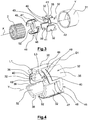
- the stator 3 comprises a yoke 31 and polar nuclei 32 distributed angularly in a regular manner on an internal face of the yoke 31.
- the polar cores 32 extend radially with respect to an internal periphery of the yoke 31 in the direction of a Y axis of the yoke 31 corresponding to the axis of the stator 3.
- the polar nuclei 32 generally have a shape of parallelepiped having an outer face 35 curved to fit the curved shape of the yoke 31 and an inner face 36 curved so as to define a substantially constant air gap 37 with an outer periphery of the rotor 2.
- the side flanks 38 of longitudinal extension of the cores 32 converge towards the Y axis of the yoke 31, as can be seen on the figure 4 .
- the polar nuclei 32 have a substantially constant thickness L1.
- the polar cores 32 are each extended by a sole 40 of generally trapezoidal shape.
- the flanges 40 have side edges 41 converging in a direction opposite to those of the pole cores 32.
- the flanges 40 extend alternately axially on the front side and the rear side of the stator 3.
- the flanges 40 have a reduced thickness L2 with respect to the thickness L1 of the polar cores 32.
- the thickness L2 of the flanges 40 is preferably decreasing when moving from the base 42 of large width of the flange 40 to the flange 40. free end 43 of the sole 40 of smaller width.
- two adjacent polar nuclei 32 are axially offset with respect to each other, that is to say that the free end 43 of a sole 40 is offset axially at a distance L3 from the end opposite of an adjacent core 32 mounted upside down. In other words, there is an axial offset of the inner edges of the successive poles. Two adjacent polar nuclei 32 thus overlap axially relative to each other.
- a winding 46 has axial corrugations 47 so as to pass between the pole cores 32.
- the coil 46 thus has an alternation of internal portions 48 located between two adjacent polar cores 32 and connecting portions 49 electrically connecting two inner portions 48 adjacent.
- each connecting portion 49 is superimposed radially at least partially with a corresponding flange 40. It is considered that two elements are superimposed radially when a straight line D1 of radial orientation passing through one of the elements intersects the other element, as shown on the figures 4 and 5 .
- each connecting portion 49 has a width L4 at least equal to 70% of the axial length L5 of a corresponding sole 40. In the exemplary embodiment shown on the figure 5 the width L4 of each connecting portion 49 is substantially equal to the axial length L5 of a corresponding sole 40.
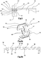
- the winding 46 is advantageously formed by a continuous strip 52 wound on several turns S1-S3 in a spiral manner, that is to say with increasing or decreasing radius of turn to turn. This thus constitutes a laminated winding according to which the edges of the set of turns S1-S3 coincide with each other.
- the winding 46 is formed by a single conductor wound spiral.
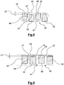
- the band 52 has indentations 53 open alternately on the front side and on the rear side of the stator 3 to form the axial corrugations 47 of the coil 46.
- a width L6 of the indentations 53 varies from one turn to the other, that is to say from one turn to the other of the winding of the band 52. Indeed, the width L6 indentations 53 increases gradually from one turn to the other.
- the winding 46 can be achieved via a stepwise punching process. In a variant, the winding 46 is made from a flat-wound flat shape.
- the band 52 may be made of aluminum or copper.
- the strip 52 is made of an aluminum-based material which has the advantage of being easy to cut and deform to obtain the winding of turns.
- the winding 46 corresponds to a global winding of three turns S1-S3 of the band 52 electrically connected in series.
- the three turns are thus formed by one and the same piece.
- the number of turns can of course be adapted according to the application.
- the strip 52 is covered with an electrically insulating material 56 (cf. figure 6b ). This makes it possible to electrically isolate the winding 46 with respect to the pole cores 32 and to the yoke 31 of the stator 3.
- the insulating material 56 is constituted for example by enamel and / or an insulating paper or obtained by anodizing the aluminum. Alternatively, the insulating material 56 may be overmoulded around the electrically conductive strip 52.
- the rotating electrical machine When the winding 46 is traversed by a current, it produces an inductor field so as to form an alternation of North and South poles following the circumference of the stator 3.
- the rotating electrical machine comprises six polar nuclei 32 , so six poles.
- the rotating electrical machine may have a different number of poles, such as four poles or more than six poles.
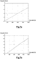
- the shape of the overlapped polar cores 32 combined with the use of the winding 46 makes it possible to substantially increase the torque generated by the starter 1 for a current of 1000 amperes corresponding to the starting current of the electric motor relative to a starter according to the state of the art provided with non-overlapped polar cores 32 and an annular winding.
- the torque generated at 1000A is of the order of 10 N.m for a starter according to the invention (see curve of FIG. figure 7b ) while it is only of the order of 7N.m for a starter according to the state of the art (see curve 7a).
- the pole cores 32 each have an end edge 57 rounded on the side of a contact zone with the coil 46. This makes it possible to reduce the length of the effective path of the field lines of the current density. This reduces the resistance of the winding through the total volume of the winding inductor and the corresponding energy losses equal to Ri ⁇ 2.
- a section L7 of the inner portions 48 of the coil 46 and a section L8 of the connecting portions 49 of the coil 46 are different from each other.
- the polar nuclei 32 are each extended by a bloom extending circumferentially on either side of the central portion.
Landscapes
- Engineering & Computer Science (AREA)
- Power Engineering (AREA)
- Iron Core Of Rotating Electric Machines (AREA)
- Windings For Motors And Generators (AREA)
Applications Claiming Priority (1)
| Application Number | Priority Date | Filing Date | Title |
|---|---|---|---|
| FR1654821A FR3051989A1 (fr) | 2016-05-27 | 2016-05-27 | Demarreur de vehicule automobile muni d'un stator a performances magnetiques ameliorees |
Publications (1)
| Publication Number | Publication Date |
|---|---|
| EP3249793A1 true EP3249793A1 (de) | 2017-11-29 |
Family
ID=56511767
Family Applications (1)
| Application Number | Title | Priority Date | Filing Date |
|---|---|---|---|
| EP17172228.3A Withdrawn EP3249793A1 (de) | 2016-05-27 | 2017-05-22 | Kraftfahrzeugstarter mit einem ständer mit verbesserter magnetischer leistung |
Country Status (2)
| Country | Link |
|---|---|
| EP (1) | EP3249793A1 (de) |
| FR (1) | FR3051989A1 (de) |
Citations (3)
| Publication number | Priority date | Publication date | Assignee | Title |
|---|---|---|---|---|
| FR1429849A (fr) * | 1965-04-09 | 1966-02-25 | Lucas Industries Ltd | Stator pour machine dynamo-électrique |
| DE29623132U1 (de) * | 1996-06-20 | 1997-11-06 | Robert Bosch Gmbh, 70469 Stuttgart | Gleichstrommotor |
| DE19757068C1 (de) * | 1997-12-20 | 1999-07-15 | Bosch Gmbh Robert | Verfahren und Vorrichtung zum Herstellen einer Formspule für eine Erregerwicklung |
-
2016
- 2016-05-27 FR FR1654821A patent/FR3051989A1/fr not_active Ceased
-
2017
- 2017-05-22 EP EP17172228.3A patent/EP3249793A1/de not_active Withdrawn
Patent Citations (3)
| Publication number | Priority date | Publication date | Assignee | Title |
|---|---|---|---|---|
| FR1429849A (fr) * | 1965-04-09 | 1966-02-25 | Lucas Industries Ltd | Stator pour machine dynamo-électrique |
| DE29623132U1 (de) * | 1996-06-20 | 1997-11-06 | Robert Bosch Gmbh, 70469 Stuttgart | Gleichstrommotor |
| DE19757068C1 (de) * | 1997-12-20 | 1999-07-15 | Bosch Gmbh Robert | Verfahren und Vorrichtung zum Herstellen einer Formspule für eine Erregerwicklung |
Also Published As
| Publication number | Publication date |
|---|---|
| FR3051989A1 (fr) | 2017-12-01 |
Similar Documents
| Publication | Publication Date | Title |
|---|---|---|
| EP3166210B1 (de) | Elektrisch umlaufende maschine, die mit einem stator ausgestattet ist | |
| FR2939570A1 (fr) | Dispositif a balais pour demarreur de vehicule automobile. | |
| EP2901527B1 (de) | Bürste einer elektrischen maschine sowie zugehöriger bürstenhalter | |
| FR2992493A1 (fr) | Isolant de bobine muni d'une ailette formant un mur electriquement isolant et element de machine electrique associe | |
| WO2014041313A1 (fr) | Stator a dents rapportees pour machine electrique tournante et machine electrique tournante correspondante | |
| EP3072218A1 (de) | Niedrigleistungsstarter mit optimierter grösse für ein kraftfahrzeug | |
| EP2860847B1 (de) | Bewickelter Stator mit optimierter Nutenfüllung, und entsprechende elektrische Maschine | |
| WO2014049290A1 (fr) | Cage a balai pour porte-balai de machine electrique et porte-balais correspondant | |
| FR2995470A1 (fr) | Isolant de bobine realise en deux parties et element de machine electrique correspondant | |
| EP3249793A1 (de) | Kraftfahrzeugstarter mit einem ständer mit verbesserter magnetischer leistung | |
| EP2564494A1 (de) | Elektromaschine mit einem rotor mit einer wicklung für umschaltung und zugehöriger starter | |
| EP2446136B1 (de) | Vorrichtung für die bürsten einer rotierenden elektrischen maschine, insbesondere für den verbrennungsmotor eines kraftfahrzeugs | |
| EP3571755B1 (de) | Spulenstator für rotierende elektrische maschine | |
| FR3051295A1 (fr) | Machine electrique tournante a puissance augmentee | |
| EP2313951A2 (de) | Bürsteneinrichtung für einen kraftfahrzeuganlasser | |
| EP2846438A2 (de) | Spulenisolierung | |
| EP2452406B1 (de) | Kommutator einer drehenden elektrischen maschine für ein fahrzeug | |
| FR2934436A1 (fr) | Dispositif a balais pour demarreur de vehicule automobile | |
| EP3214734A1 (de) | Stator einer elektrisch umlaufenden maschine, der mit einer spulenwicklung mit mindestens einer maskierten phase ausgestattet ist | |
| FR3039938A1 (fr) | Ensemble pour machine electrique tournante comportant un collecteur fixe au moyen d'une goupille | |
| FR3052001A1 (fr) | Machine electrique tournante a configuration amelioree | |
| FR3055755B1 (fr) | Machine electrique tournante comprenant un ensemble electronique demontable | |
| WO2016162635A1 (fr) | Stator de demarreur pour vehicule automobile a plage de remanence optimisee | |
| FR2992496A1 (fr) | Isolant de bobine muni de rainures pour faciliter l'impregnation de la bobine et element de machine electrique associe | |
| WO2015145008A1 (fr) | Machine électrique tournante a couplage de phases optimise et procédé de réalisation de bobinage correspondant |
Legal Events
| Date | Code | Title | Description |
|---|---|---|---|
| PUAI | Public reference made under article 153(3) epc to a published international application that has entered the european phase |
Free format text: ORIGINAL CODE: 0009012 |
|
| 17P | Request for examination filed |
Effective date: 20170522 |
|
| AK | Designated contracting states |
Kind code of ref document: A1 Designated state(s): AL AT BE BG CH CY CZ DE DK EE ES FI FR GB GR HR HU IE IS IT LI LT LU LV MC MK MT NL NO PL PT RO RS SE SI SK SM TR |
|
| AX | Request for extension of the european patent |
Extension state: BA ME |
|
| STAA | Information on the status of an ep patent application or granted ep patent |
Free format text: STATUS: THE APPLICATION IS DEEMED TO BE WITHDRAWN |
|
| 18D | Application deemed to be withdrawn |
Effective date: 20191203 |