EP3249902A1 - On-vehicle camera device - Google Patents
On-vehicle camera device Download PDFInfo
- Publication number
- EP3249902A1 EP3249902A1 EP16740008.4A EP16740008A EP3249902A1 EP 3249902 A1 EP3249902 A1 EP 3249902A1 EP 16740008 A EP16740008 A EP 16740008A EP 3249902 A1 EP3249902 A1 EP 3249902A1
- Authority
- EP
- European Patent Office
- Prior art keywords
- image
- region
- data
- diagnosis
- imaging element
- Prior art date
- Legal status (The legal status is an assumption and is not a legal conclusion. Google has not performed a legal analysis and makes no representation as to the accuracy of the status listed.)
- Withdrawn
Links
Images


Classifications
-
- G—PHYSICS
- G08—SIGNALLING
- G08G—TRAFFIC CONTROL SYSTEMS
- G08G1/00—Traffic control systems for road vehicles
- G08G1/16—Anti-collision systems
-
- H—ELECTRICITY
- H04—ELECTRIC COMMUNICATION TECHNIQUE
- H04N—PICTORIAL COMMUNICATION, e.g. TELEVISION
- H04N17/00—Diagnosis, testing or measuring for television systems or their details
- H04N17/002—Diagnosis, testing or measuring for television systems or their details for television cameras
-
- H—ELECTRICITY
- H04—ELECTRIC COMMUNICATION TECHNIQUE
- H04N—PICTORIAL COMMUNICATION, e.g. TELEVISION
- H04N23/00—Cameras or camera modules comprising electronic image sensors; Control thereof
- H04N23/60—Control of cameras or camera modules
-
- H—ELECTRICITY
- H04—ELECTRIC COMMUNICATION TECHNIQUE
- H04N—PICTORIAL COMMUNICATION, e.g. TELEVISION
- H04N25/00—Circuitry of solid-state image sensors [SSIS]; Control thereof
- H04N25/40—Extracting pixel data from image sensors by controlling scanning circuits, e.g. by modifying the number of pixels sampled or to be sampled
- H04N25/44—Extracting pixel data from image sensors by controlling scanning circuits, e.g. by modifying the number of pixels sampled or to be sampled by partially reading an SSIS array
-
- H—ELECTRICITY
- H04—ELECTRIC COMMUNICATION TECHNIQUE
- H04N—PICTORIAL COMMUNICATION, e.g. TELEVISION
- H04N25/00—Circuitry of solid-state image sensors [SSIS]; Control thereof
- H04N25/60—Noise processing, e.g. detecting, correcting, reducing or removing noise
- H04N25/68—Noise processing, e.g. detecting, correcting, reducing or removing noise applied to defects
-
- H—ELECTRICITY
- H04—ELECTRIC COMMUNICATION TECHNIQUE
- H04N—PICTORIAL COMMUNICATION, e.g. TELEVISION
- H04N7/00—Television systems
- H04N7/18—Closed-circuit television [CCTV] systems, i.e. systems in which the video signal is not broadcast
Definitions
- the present invention relates to an on-vehicle camera device.
- a technology in which a failure detection pattern region is formed in an ineffective pixel region, an image signal is read out from the entire region of an effective pixel region, and then, a failure detection pattern is read out by switching a driving method to a driving method different from that of the effective pixel region, and a case where a signal according to the pattern is not output is determined as failure.
- the image signal of the effective pixel region is read out, and then, the failure detection pattern is read out by switching the driving method, and thus, the entire reading out period is longer by that much, the start of image recognition processing is delayed, and an operation using an image recognition result is delayed. In addition, there is a concern that image processing is paused while the failure detection pattern is read out.
- An object of the present invention is to swiftly and accurately detect, in every frame, data line signals of respective bits from imaging elements.
- an on-vehicle camera device includes: a failure-diagnosis processing unit that diagnoses whether a data line signal of an imaging element unit is in a fixed state, wherein the imaging element unit includes an entire imaging region that is divided into an effective image region in which image data to be output is used for image-calculation and an ineffective image region in which the image data to be output is not used for the image-calculation, and includes a diagnosis data region that includes fixation diagnosis data for diagnosing whether the data line signal of the imaging element unit is in the fixed state in the ineffective image region, and the failure-diagnosis processing unit uses the fixation diagnosis data of the diagnosis data region to perform failure-diagnosis processing in an image acquisition period in which image data of the entire imaging region is acquired and/or an image-calculation processing period in which image-calculation processing is performed on the basis of image data of the effective image region after the image acquisition period.
- the on-vehicle camera device which is capable of accurately detecting that any one of the data line signals from the imaging element is in the fixed state, abnormality occurs in a luminance value of the acquired image data, and suitable parallax calculation processing and image recognition processing are not capable of being performed, and thus, a state is obtained in which a target distance is not capable of being calculated, and of providing a safety driving system having higher reliability.
- Examples of a safety driving support system of an automobile include an inter-vehicle distance alarm system, an adaptive cruise control system, a pre-crash brake system, and the like, and a sensing technology of accurately recognizing the environment in the front of the vehicle, such as a preceding vehicle, a driving lane, and an obstacle in the periphery of the own vehicle, is essential at the time of constructing the systems described above.
- Examples of a sensor recognizing the environment in the front of the vehicle include an on-vehicle camera device.
- a stereo camera is capable of recognizing a solid object form parallax information of right and left cameras, and thus, is excellent in the detection of a solid object having an arbitrary shape, such as a pedestrian or curbstone.
- parallax is calculated according to a difference in luminance information of images acquired at the same timing from imaging element units of the camera, which are attached to the camera on a right side and a left side in a vehicle traveling direction, and thus, the solid object can be recognized.
- fixed value data for data line signal fixation diagnosis is embedded in an ineffective image region other than an effective image region used in an image recognition processing unit, in an image region output from an imaging element, and data line signal fixation diagnosis is suitably executed, in every frame, at a suitable timing.
- One representative example of the on-vehicle camera devices of the present invention is a stereo camera 201 including two imaging elements, and image data illustrated in FIG. 1 is acquired from the imaging element.
- FIG. 1 is a diagram illustrating a configuration of an output image region of an imaging element of this example.
- An entire imaging region 101 is image data of an entire screen output by an imaging element, and has a configuration including an effective image region 102, an ineffective image region 103, and a diagnosis data region 104.
- the effective image region 102 for example, is a region including image data which is used in an image recognition processing unit 207 for recognizing a solid object
- the ineffective image region 103 is a region in which image data is not used in the image recognition processing unit 207.
- the diagnosis data region 104 is a region stored in a part of the ineffective image region 103.
- the entire imaging region 101 is divided into the effective image region 102 in which the image data to be output is used for image-calculation and the ineffective image region 103 in which the image data to be output is not used for the image-calculation, and includes the diagnosis data region 104 including fixation diagnosis data for diagnosing whether a data line signal of an imaging element unit in the ineffective image region 103 is in the fixed state.
- the position or the size of the effective image region 102 is capable of being fixed or of varying according to the application.
- the diagnosis data region 104 includes the fixation diagnosis data which is capable of detecting the fixed state of the data line signal, and specifically, includes HI level fixation diagnosis data 302 which is fixed value data capable of detecting an HI level fixed state of the data line signal and LO level fixation diagnosis data 301 which is fixed value data capable of detecting an LO level fixed state of the data line signal.
- the diagnosis data region 104 is provided in a position on a front side of the effective image region 102 in a data acquisition direction in which the image data is acquired, and in this example, is provided on an upper left corner of the entire imaging region 101.
- FIG. 3 is a configuration diagram of the diagnosis data region, and is a diagram illustrating a configuration example of the fixation diagnosis data in a case of using an imaging element having 16-bit gradation.
- the LO level fixation diagnosis data 301 includes diagnosis data of minimum 16 pixels in order to execute fixation diagnosis of a data line signal of the 16-bit gradation.
- expected value data which is embedded in the ineffective image region 103 as diagnosis data sets a value in which only a bit corresponding to a diagnosis target data line bit is HI and the other bits are LO.
- expected value data for detecting an LO level fixed state of Bit 0 sets 0x0001 (only the value of the Bit 0 is HI) as diagnosis 16-bit data.
- the value of a pixel in which LO level fixation diagnosis data of Bit 0 is stored is 0x0000 at the time of acquiring the image data output from the imaging element, and thus, the data line signal can be diagnosed as being in the LO level fixed state.
- LO level fixation diagnosis data items of Bit 1 to Bit 15 are similarly set.
- the HI level fixation diagnosis data 302 also includes diagnosis data of 16 pixels as with the gradation of the imaging element.
- expected value data which is embedded in the ineffective image region 103 as diagnosis data sets a value in which only a bit corresponding to a diagnosis target data line bit is LO, and the other bits are HI.
- expected value data for detecting an HI level fixed state of the Bit 0 sets 0xFFFE (the value of the Bit 0 is LO) as the diagnosis 16-bit data.
- the value of a pixel in which HI level fixation diagnosis data of the Bit 0 is stored is 0xFFFF at the time of acquiring the image data output from the imaging element, and thus, the data line signal can be diagnosed as being in the HI level fixed state.
- HI level fixation diagnosis data items of the Bit 1 to the Bit 15 are similarly set.
- the fixation diagnosis data described above is output from the imaging element, and a storage portion of the fixation diagnosis data at an image data acquisition time point is confirmed, and thus, the LO level fixed state or the HI level fixed state of the data line signal can be detected.
- FIG. 2 is a block configuration diagram of the stereo camera 201 according to an example of the present invention.
- the stereo camera 201 includes a right imaging element unit 202 attached to the stereo camera 201 on a right side in the vehicle traveling direction, a left imaging element unit 203 attached to the stereo camera 201 on a left side in the vehicle traveling direction, an image data acquisition unit 204 acquiring image data which is output from the right imaging element unit 202 and the left imaging element unit 203, an image-calculation processing unit 205 calculating parallax information or the like required for recognition processing of the solid object from the right and left image data items which are acquired in the image data acquisition unit 204, an image data transmission unit 206 transmitting the right and left image data items acquired in the image data acquisition unit 204 or the image data generated in the image-calculation processing unit 205 to a processing region to be used, an image recognition processing unit 207 executing solid object recognition or the like on the basis of various image data items such as the parallax information, a failure-diagnosis processing unit 208 executing failure-diagnosis of whether the data line signal is in the fixed state by using the image data line fixation
- the stereo camera 201 connects vehicle control information calculated by the vehicle control processing unit 209 or failure information output from the notification processing unit 210 to an on-vehicle communication bus 211 such as a controller area network (CAN), and transmits output information of the stereo camera 201 to an external ECU.
- an on-vehicle communication bus 211 such as a controller area network (CAN)
- CAN controller area network
- Each of the right imaging element unit 202 and the left imaging element unit 203 has a configuration in which a plurality of pixels are arranged in a matrix.
- Image data items of images which are imaged by the right imaging element unit 202 and the left imaging element unit 203 are acquired by the image data acquisition unit 204.
- the image data is acquired from a pixel on a left edge of a first column of the entire imaging region 101 towards a right edge in a row direction, and all image data items of the entire imaging region 101 (the image data items of the entire screen) are acquired while sequentially proceeding to a lower side after a second column in a column direction.
- the diagnosis data region 104 is provided on an upper left corner of the entire imaging region 101, and thus, is initially acquired when the image data is acquired from the entire imaging region 101.
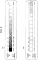
- FIG. 4 is a diagram illustrating an example of a timing from the acquisition of the image data from the right imaging element unit 202 and the left imaging element unit 203 to the start of the processing in the image recognition processing unit 207.
- a vertical synchronization signal 401 representing an image data acquisition timing from the imaging element is an HI level signal during an image data output period
- the vertical synchronization signal 401 is in an HI level during data of the number of all effective lines output from the imaging element is acquired in the image data acquisition unit 204, that is, during the image data of the entire imaging region 101 is acquired.
- the vertical synchronization signal 401 is in an LO level at a time point t1 at which the acquisition of the image data of the entire imaging region 101 is completed in the image data acquisition unit 204, and the image-calculation processing starts at the same timing in the image-calculation processing unit 205. Then, the image data items required for the solid object recognition are arranged at a time point t2 at which the calculation processing of the image-calculation processing unit 205 is completed, and thus, the calculation processing of the image recognition processing unit 207 starts. Accordingly, the fixed state of the data line signal from the imaging element is required to be detected until the calculation processing of the image recognition processing unit 207 starts.
- the diagnosis data region 104 is provided in the ineffective image region 103, and the fixation diagnosis data of the diagnosis data region 104 is also acquired when the image data of the entire imaging region 101 is acquired by the image data acquisition unit 204, and thus, it is possible to diagnose the fixed state of the data line signal until the recognition processing starts, that is, in an image acquisition period and/or an image-calculation processing period. Therefore, it is possible to swiftly and accurately detect that the data line signal from the imaging element is in the fixed state and a state is obtained in which the solid object recognition is not normally executed, without being affected by the environment such as contrast, and to provide a driving support system having higher reliability.
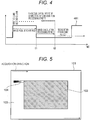
- a data line fixation diagnosis data region of the present invention also includes an aspect in which storage is performed in a region illustrated in FIG. 5 as an example.
- FIG. 5 is a diagram illustrating an example of a storage destination of the data line fixation diagnosis data region.
- the characteristic of this example is that the diagnosis data region 104 is provided in a position immediately before the image data of the effective image region 102 is acquired.
- the diagnosis data region 104 is continuously provided on a front side of a starting point at which the acquisition of the image data of the effective image region 102 starts, in the data acquisition direction.
- the image data is acquired from the left edge of the entire imaging region 101 towards the right edge, and all of the image data items of the entire imaging region 101 are acquired by sequentially proceeding to the lower side, and thus, the diagnosis data region 104 is continuously provided in a position on a left side of the starting point which is an upper left edge of the effective image region 102 in the drawing.
- the data line fixation diagnosis data region of the present invention also includes an aspect in which storage is performed in a region illustrated in FIG. 6 as an example.
- FIG. 6 is a diagram illustrating an example of the storage destination of the data line fixation diagnosis data region.
- diagnosis data region 104 is provided on a rear side of the effective image region 102 in the data acquisition direction, in particular, is provided in a position immediately after all of the image data items of the effective image region 102 are acquired.
- the diagnosis data region 104 is continuously provided on a rear side of an ending point at which the acquisition of the image data of the effective image region 102 ends, in the data acquisition direction.
- the image data is acquired from the left edge of the entire imaging region 101 towards the right edge, and all of the image data items of the entire imaging region 101 are acquired by sequentially proceeding to the lower side, and thus, the diagnosis data region 104 is continuously provided in a position on a right side of the ending point which is a lower right edge of the effective image region 102 in the drawing.
- FIG. 7 is a diagram illustrating an example of a timing at which the diagnosis processing is executed with respect to the right and left imaging element units.
- a calculation processing load of the image recognition processing unit 207 varies according to the image data output from the imaging element. For example, in a case of acquiring image data in which there are a plurality of targets of the solid object such as a preceding vehicle or a pedestrian while the vehicle travels, a plurality of solid object sensing processing are operated, and thus, the processing load increases. In contrast, in a case of acquiring image data in which there is no solid object and no target to be recognized while the vehicle stops, the processing load of the image recognition processing unit 207 decreases.
- a case occurs in which the image recognition processing is not completed within a predetermined period of time due to the influence of the processing load generated in the execution of the failure-diagnosis, according to the hardware constraint condition of the stereo camera 201.
- the number of imaging element units executing the fixation diagnosis of the data line signal is limited, and thus, the influence on the execution of the recognition processing can be minimally suppressed.
- the fixation diagnosis of the data line signal with respect to the imaging element unit outputting the image data of which the degree of priority is high is preferentially executed.
- the fixation diagnosis of the data line signal of the same imaging element unit is planned to be preferentially executed.
- FIG. 8 is a flowchart illustrating switching of processing details according to a degree of priority and a processing load.
- the confirmation of a degree of priority of the imaging element unit is executed (S801).
- degrees of priority are set with respect to each other.
- the diagnosis processing of the imaging element unit on a side where the degree of priority is high is executed regardless of the magnitude of the processing load.
- the confirmation of the processing load status of the corresponding frame is executed (S802), and it is determined whether the diagnosis processing is executed.
- both of the diagnosis processing of the right imaging element unit 202 on a side where the degree of priority is high and the diagnosis processing of the left imaging element unit 203 on a side where the degree of priority is low are executed, on the basis of the determination that the processing load during a recognition processing period of a frame 2 is less than the standard value (Processing Load: Small).
Landscapes
- Engineering & Computer Science (AREA)
- Multimedia (AREA)
- Signal Processing (AREA)
- Physics & Mathematics (AREA)
- General Physics & Mathematics (AREA)
- Health & Medical Sciences (AREA)
- Biomedical Technology (AREA)
- General Health & Medical Sciences (AREA)
- Studio Devices (AREA)
- Traffic Control Systems (AREA)
- Transforming Light Signals Into Electric Signals (AREA)
- Testing, Inspecting, Measuring Of Stereoscopic Televisions And Televisions (AREA)
Abstract
Description
- The present invention relates to an on-vehicle camera device.
- In
PTL 1, a technology is disclosed in which a failure detection pattern region is formed in an ineffective pixel region, an image signal is read out from the entire region of an effective pixel region, and then, a failure detection pattern is read out by switching a driving method to a driving method different from that of the effective pixel region, and a case where a signal according to the pattern is not output is determined as failure. - PTL 1: Japanese Patent Application Laid-Open No.
2009-118427 - In the technology of
PTL 1, the image signal of the effective pixel region is read out, and then, the failure detection pattern is read out by switching the driving method, and thus, the entire reading out period is longer by that much, the start of image recognition processing is delayed, and an operation using an image recognition result is delayed. In addition, there is a concern that image processing is paused while the failure detection pattern is read out. - An object of the present invention is to swiftly and accurately detect, in every frame, data line signals of respective bits from imaging elements.
- In order to solve the above issue, an on-vehicle camera device according to the present invention includes: a failure-diagnosis processing unit that diagnoses whether a data line signal of an imaging element unit is in a fixed state, wherein the imaging element unit includes an entire imaging region that is divided into an effective image region in which image data to be output is used for image-calculation and an ineffective image region in which the image data to be output is not used for the image-calculation, and includes a diagnosis data region that includes fixation diagnosis data for diagnosing whether the data line signal of the imaging element unit is in the fixed state in the ineffective image region, and the failure-diagnosis processing unit uses the fixation diagnosis data of the diagnosis data region to perform failure-diagnosis processing in an image acquisition period in which image data of the entire imaging region is acquired and/or an image-calculation processing period in which image-calculation processing is performed on the basis of image data of the effective image region after the image acquisition period.
- According to the present invention, it is possible to construct the on-vehicle camera device which is capable of accurately detecting that any one of the data line signals from the imaging element is in the fixed state, abnormality occurs in a luminance value of the acquired image data, and suitable parallax calculation processing and image recognition processing are not capable of being performed, and thus, a state is obtained in which a target distance is not capable of being calculated, and of providing a safety driving system having higher reliability.
-
- [
FIG. 1] FIG. 1 is a diagram illustrating a configuration of an output image region of an imaging element of an example. - [
FIG. 2] FIG. 2 is a block configuration diagram of a stereo camera. - [
FIG. 3] FIG. 3 is a configuration diagram of a diagnosis data region. - [
FIG. 4] FIG. 4 is a diagram illustrating an example of a timing from acquisition of image data from right and left imaging element units to execution of image recognition processing. - [
FIG. 5] FIG. 5 is a diagram illustrating an example of a storage destination of a data line fixation diagnosis data region. - [
FIG. 6] FIG. 6 is a diagram illustrating an example of the storage destination of the data line fixation diagnosis data region. - [
FIG. 7] FIG. 7 is a diagram illustrating an example of a timing of executing diagnosis processing with respect to the right and left imaging element units. - [
FIG. 8] FIG. 8 is a flowchart illustrating switching of processing details according to a degree of priority and a processing load. - Hereinafter, examples according to the present invention will be described in detail with reference to the attached drawings. Furthermore, in the following description, a case of a stereo camera will be described as an example, but the present invention is not limited to the stereo camera, and can also be applied to an on-vehicle camera device including a monocular camera or a plurality of cameras.
- Examples of a safety driving support system of an automobile include an inter-vehicle distance alarm system, an adaptive cruise control system, a pre-crash brake system, and the like, and a sensing technology of accurately recognizing the environment in the front of the vehicle, such as a preceding vehicle, a driving lane, and an obstacle in the periphery of the own vehicle, is essential at the time of constructing the systems described above. Examples of a sensor recognizing the environment in the front of the vehicle include an on-vehicle camera device.
- Among the on-vehicle camera devices, a stereo camera is capable of recognizing a solid object form parallax information of right and left cameras, and thus, is excellent in the detection of a solid object having an arbitrary shape, such as a pedestrian or curbstone. In the stereo camera, parallax is calculated according to a difference in luminance information of images acquired at the same timing from imaging element units of the camera, which are attached to the camera on a right side and a left side in a vehicle traveling direction, and thus, the solid object can be recognized.
- However, in a case where a data line signal, which is an output signal, is in a fixed state due to disconnection or short-circuit in a data line with respect to the right and left imaging element units, an image obtained in an image recognition processing unit is luminance information different from that of the actual environment, and thus, an abnormal parallax calculation result is obtained, and the solid object is not capable of being suitably detected. Therefore, in order to ensure the reliability of the stereo camera, a diagnosis function for detecting that the data line signal from the imaging element unit is in the fixed state is required.
- In an on-vehicle camera device of the present invention, fixed value data for data line signal fixation diagnosis is embedded in an ineffective image region other than an effective image region used in an image recognition processing unit, in an image region output from an imaging element, and data line signal fixation diagnosis is suitably executed, in every frame, at a suitable timing.
- One representative example of the on-vehicle camera devices of the present invention is a
stereo camera 201 including two imaging elements, and image data illustrated inFIG. 1 is acquired from the imaging element. -
FIG. 1 is a diagram illustrating a configuration of an output image region of an imaging element of this example. - An
entire imaging region 101 is image data of an entire screen output by an imaging element, and has a configuration including aneffective image region 102, anineffective image region 103, and adiagnosis data region 104. Theeffective image region 102, for example, is a region including image data which is used in an imagerecognition processing unit 207 for recognizing a solid object, and theineffective image region 103 is a region in which image data is not used in the imagerecognition processing unit 207. Then, thediagnosis data region 104 is a region stored in a part of theineffective image region 103. That is, theentire imaging region 101 is divided into theeffective image region 102 in which the image data to be output is used for image-calculation and theineffective image region 103 in which the image data to be output is not used for the image-calculation, and includes thediagnosis data region 104 including fixation diagnosis data for diagnosing whether a data line signal of an imaging element unit in theineffective image region 103 is in the fixed state. - The position or the size of the
effective image region 102 is capable of being fixed or of varying according to the application. Thediagnosis data region 104 includes the fixation diagnosis data which is capable of detecting the fixed state of the data line signal, and specifically, includes HI levelfixation diagnosis data 302 which is fixed value data capable of detecting an HI level fixed state of the data line signal and LO levelfixation diagnosis data 301 which is fixed value data capable of detecting an LO level fixed state of the data line signal. Thediagnosis data region 104 is provided in a position on a front side of theeffective image region 102 in a data acquisition direction in which the image data is acquired, and in this example, is provided on an upper left corner of theentire imaging region 101. -
FIG. 3 is a configuration diagram of the diagnosis data region, and is a diagram illustrating a configuration example of the fixation diagnosis data in a case of using an imaging element having 16-bit gradation. - The LO level
fixation diagnosis data 301 includes diagnosis data of minimum 16 pixels in order to execute fixation diagnosis of a data line signal of the 16-bit gradation. In order to detect the LO level fixed state of the data line signal, expected value data which is embedded in theineffective image region 103 as diagnosis data sets a value in which only a bit corresponding to a diagnosis target data line bit is HI and the other bits are LO. - For example, expected value data for detecting an LO level fixed state of
Bit 0 sets 0x0001 (only the value of theBit 0 is HI) as diagnosis 16-bit data. In a case where a data line signal of theBit 0 is in the LO level fixed state, the value of a pixel in which LO level fixation diagnosis data ofBit 0 is stored is 0x0000 at the time of acquiring the image data output from the imaging element, and thus, the data line signal can be diagnosed as being in the LO level fixed state. LO level fixation diagnosis data items ofBit 1 toBit 15 are similarly set. - Similarly, the HI level
fixation diagnosis data 302 also includes diagnosis data of 16 pixels as with the gradation of the imaging element. In order to detect the HI level fixed state of the data line signal, expected value data which is embedded in theineffective image region 103 as diagnosis data sets a value in which only a bit corresponding to a diagnosis target data line bit is LO, and the other bits are HI. - For example, expected value data for detecting an HI level fixed state of the
Bit 0 sets 0xFFFE (the value of theBit 0 is LO) as the diagnosis 16-bit data. In a case where a data line of theBit 0 is in the HI level fixed state, the value of a pixel in which HI level fixation diagnosis data of theBit 0 is stored is 0xFFFF at the time of acquiring the image data output from the imaging element, and thus, the data line signal can be diagnosed as being in the HI level fixed state. HI level fixation diagnosis data items of theBit 1 to theBit 15 are similarly set. - The fixation diagnosis data described above is output from the imaging element, and a storage portion of the fixation diagnosis data at an image data acquisition time point is confirmed, and thus, the LO level fixed state or the HI level fixed state of the data line signal can be detected.
-
FIG. 2 is a block configuration diagram of thestereo camera 201 according to an example of the present invention. - The
stereo camera 201 includes a rightimaging element unit 202 attached to thestereo camera 201 on a right side in the vehicle traveling direction, a leftimaging element unit 203 attached to thestereo camera 201 on a left side in the vehicle traveling direction, an imagedata acquisition unit 204 acquiring image data which is output from the rightimaging element unit 202 and the leftimaging element unit 203, an image-calculation processing unit 205 calculating parallax information or the like required for recognition processing of the solid object from the right and left image data items which are acquired in the imagedata acquisition unit 204, an imagedata transmission unit 206 transmitting the right and left image data items acquired in the imagedata acquisition unit 204 or the image data generated in the image-calculation processing unit 205 to a processing region to be used, an imagerecognition processing unit 207 executing solid object recognition or the like on the basis of various image data items such as the parallax information, a failure-diagnosis processing unit 208 executing failure-diagnosis of whether the data line signal is in the fixed state by using the image data line fixation diagnosis data, a vehiclecontrol processing unit 209 calculating vehicle control processing on the basis of a recognition result detected by the imagerecognition processing unit 207, and anotification processing unit 210 for transmitting an abnormal state to the outside when the abnormality is determined by the failure-diagnosis processing unit 208. - In addition, the
stereo camera 201 connects vehicle control information calculated by the vehiclecontrol processing unit 209 or failure information output from thenotification processing unit 210 to an on-vehicle communication bus 211 such as a controller area network (CAN), and transmits output information of thestereo camera 201 to an external ECU. - Each of the right
imaging element unit 202 and the leftimaging element unit 203 has a configuration in which a plurality of pixels are arranged in a matrix. Image data items of images which are imaged by the rightimaging element unit 202 and the leftimaging element unit 203 are acquired by the imagedata acquisition unit 204. In this example, in each of the rightimaging element unit 202 and the leftimaging element unit 203, the image data is acquired from a pixel on a left edge of a first column of theentire imaging region 101 towards a right edge in a row direction, and all image data items of the entire imaging region 101 (the image data items of the entire screen) are acquired while sequentially proceeding to a lower side after a second column in a column direction. Then, the image data of theeffective image region 102 from all of the acquired image data items is used for the image-calculation processing of the image-calculation processing unit 205. Thediagnosis data region 104 is provided on an upper left corner of theentire imaging region 101, and thus, is initially acquired when the image data is acquired from theentire imaging region 101. -
FIG. 4 is a diagram illustrating an example of a timing from the acquisition of the image data from the rightimaging element unit 202 and the leftimaging element unit 203 to the start of the processing in the imagerecognition processing unit 207. - As an example in which a
vertical synchronization signal 401 representing an image data acquisition timing from the imaging element is an HI level signal during an image data output period, thevertical synchronization signal 401 is in an HI level during data of the number of all effective lines output from the imaging element is acquired in the imagedata acquisition unit 204, that is, during the image data of theentire imaging region 101 is acquired. - The
vertical synchronization signal 401 is in an LO level at a time point t1 at which the acquisition of the image data of theentire imaging region 101 is completed in the imagedata acquisition unit 204, and the image-calculation processing starts at the same timing in the image-calculation processing unit 205. Then, the image data items required for the solid object recognition are arranged at a time point t2 at which the calculation processing of the image-calculation processing unit 205 is completed, and thus, the calculation processing of the imagerecognition processing unit 207 starts. Accordingly, the fixed state of the data line signal from the imaging element is required to be detected until the calculation processing of the imagerecognition processing unit 207 starts. - According to the present invention, the
diagnosis data region 104 is provided in theineffective image region 103, and the fixation diagnosis data of thediagnosis data region 104 is also acquired when the image data of theentire imaging region 101 is acquired by the imagedata acquisition unit 204, and thus, it is possible to diagnose the fixed state of the data line signal until the recognition processing starts, that is, in an image acquisition period and/or an image-calculation processing period. Therefore, it is possible to swiftly and accurately detect that the data line signal from the imaging element is in the fixed state and a state is obtained in which the solid object recognition is not normally executed, without being affected by the environment such as contrast, and to provide a driving support system having higher reliability. - A data line fixation diagnosis data region of the present invention also includes an aspect in which storage is performed in a region illustrated in
FIG. 5 as an example.FIG. 5 is a diagram illustrating an example of a storage destination of the data line fixation diagnosis data region. - The characteristic of this example is that the
diagnosis data region 104 is provided in a position immediately before the image data of theeffective image region 102 is acquired. - The
diagnosis data region 104 is continuously provided on a front side of a starting point at which the acquisition of the image data of theeffective image region 102 starts, in the data acquisition direction. In this example, the image data is acquired from the left edge of theentire imaging region 101 towards the right edge, and all of the image data items of theentire imaging region 101 are acquired by sequentially proceeding to the lower side, and thus, thediagnosis data region 104 is continuously provided in a position on a left side of the starting point which is an upper left edge of theeffective image region 102 in the drawing. By providing thediagnosis data region 104 in such a position, it is possible to diagnose the fixed state of the data line signal immediately before the image data of theeffective image region 102 is acquired from the imaging element. Therefore, for example, even in a case where the data line signal is in the fixed state from the start of the acquisition of the image data of theentire imaging region 101 from the upper left edge to the acquisition of the fixation diagnosis data of the fixationdiagnosis data region 104, it is possible to detect such a fixed state. - The data line fixation diagnosis data region of the present invention also includes an aspect in which storage is performed in a region illustrated in
FIG. 6 as an example.FIG. 6 is a diagram illustrating an example of the storage destination of the data line fixation diagnosis data region. - The characteristic of this example is that the
diagnosis data region 104 is provided on a rear side of theeffective image region 102 in the data acquisition direction, in particular, is provided in a position immediately after all of the image data items of theeffective image region 102 are acquired. - The
diagnosis data region 104 is continuously provided on a rear side of an ending point at which the acquisition of the image data of theeffective image region 102 ends, in the data acquisition direction. In this example, the image data is acquired from the left edge of theentire imaging region 101 towards the right edge, and all of the image data items of theentire imaging region 101 are acquired by sequentially proceeding to the lower side, and thus, thediagnosis data region 104 is continuously provided in a position on a right side of the ending point which is a lower right edge of theeffective image region 102 in the drawing. By providing thediagnosis data region 104 in such a position, it is possible to acquire the fixation diagnosis data from thediagnosis data region 104 immediately after all of the image data items of theeffective image region 102 are acquired. Therefore, it is possible to confirm the reliability of the image data of the corresponding frame. -
FIG. 7 is a diagram illustrating an example of a timing at which the diagnosis processing is executed with respect to the right and left imaging element units. - It is considered that a calculation processing load of the image
recognition processing unit 207 varies according to the image data output from the imaging element. For example, in a case of acquiring image data in which there are a plurality of targets of the solid object such as a preceding vehicle or a pedestrian while the vehicle travels, a plurality of solid object sensing processing are operated, and thus, the processing load increases. In contrast, in a case of acquiring image data in which there is no solid object and no target to be recognized while the vehicle stops, the processing load of the imagerecognition processing unit 207 decreases. - A case occurs in which the image recognition processing is not completed within a predetermined period of time due to the influence of the processing load generated in the execution of the failure-diagnosis, according to the hardware constraint condition of the
stereo camera 201. In order to solve the problem described above, in a case of acquiring image data in which the processing load of the image recognition processing increases, the number of imaging element units executing the fixation diagnosis of the data line signal is limited, and thus, the influence on the execution of the recognition processing can be minimally suppressed. - Here, when the image recognition processing is executed, in a case where a degree of priority of any one of the respective image data items output from the right and left
imaging element units -
FIG. 8 is a flowchart illustrating switching of processing details according to a degree of priority and a processing load. - First, the confirmation of a degree of priority of the imaging element unit is executed (S801). In a pair of right and left imaging element units, degrees of priority are set with respect to each other. In a case of the imaging element unit, which is a diagnosis target, on a side where the degree of priority is high (YES in S801), among the pair of imaging element units, the diagnosis processing of the imaging element unit on a side where the degree of priority is high is executed regardless of the magnitude of the processing load. Then, in a case of the imaging element unit on a side where the degree of priority is low, the confirmation of the processing load status of the corresponding frame is executed (S802), and it is determined whether the diagnosis processing is executed.
- In the confirmation of the processing load status (S802), in a case where it is determined that the processing load of the corresponding frame is less than a standard value set in advance (YES in S802), the diagnosis processing of the imaging element unit on a side where the degree of priority is low is also executed. In contrast, in a case where it is determined that the processing load of the corresponding frame increases (is greater than or equal to the standard value) (NO in S802), the diagnosis processing of the imaging element unit on a side where the degree of priority is low is not executed. Accordingly, the influence on the execution of the recognition processing can be minimally suppressed.
- For example, in the example illustrated in
FIG. 7 , only the diagnosis processing of the rightimaging element unit 202 on a side where the degree of priority is high is executed, and the diagnosis processing of the leftimaging element unit 203 on a side where the degree of priority is low is not executed, on the basis of the determination that the processing load during a recognition processing period of aframe 1 is greater than or equal to the standard value (Processing Load: Large). Then, both of the diagnosis processing of the rightimaging element unit 202 on a side where the degree of priority is high and the diagnosis processing of the leftimaging element unit 203 on a side where the degree of priority is low are executed, on the basis of the determination that the processing load during a recognition processing period of aframe 2 is less than the standard value (Processing Load: Small). - In the above description, various embodiments and modifications have been described, but the present invention is not limited to the contents thereof. The other aspects considered within the range of the technical ideas of the present invention are also included in the scope of the present invention.
-
- 101
- entire imaging region
- 102
- effective image region
- 103
- ineffective image region
- 104
- diagnosis data region
- 201
- stereo camera (on-vehicle camera device)
- 202
- right imaging element unit
- 203
- left imaging element unit
- 204
- image data acquisition unit
- 205
- image-calculation processing unit
- 206
- image data transmission unit
- 207
- image recognition processing unit
- 208
- failure-diagnosis processing unit
- 209
- vehicle control processing unit
- 210
- notification processing unit
- 211
- on-vehicle communication bus
- 301
- LO level fixation diagnosis data
- 302
- HI level fixation diagnosis data
- 401
- vertical synchronization signal
Claims (7)
- An on-vehicle camera device comprising:a failure-diagnosis processing unit that diagnoses whether a data line signal of an imaging element unit is in a fixed state,wherein the imaging element unit includes an entire imaging region that is divided into an effective image region in which image data to be output is used for image-calculation and an ineffective image region in which the image data to be output is not used for the image-calculation, and includes a diagnosis data region that includes fixation diagnosis data for diagnosing whether the data line signal of the imaging element unit is in the fixed state in the ineffective image region, andthe failure-diagnosis processing unit uses the fixation diagnosis data of the diagnosis data region to perform failure-diagnosis processing in an image acquisition period in which image data of the entire imaging region is acquired and/or an image-calculation processing period in which image-calculation processing is performed on the basis of image data of the effective image region after the image acquisition period.
- The on-vehicle camera device according to claim 1,
wherein the diagnosis data region is provided on a front side of the effective image region in a data acquisition direction. - The on-vehicle camera device according to claim 2,
wherein the diagnosis data region is continuously provided on a front side of a starting point at which the acquisition of the image data of the effective image region starts, in the data acquisition direction. - The on-vehicle camera device according to claim 1,
wherein the diagnosis data region is provided on a rear side of the effective image region in a data acquisition direction. - The on-vehicle camera device according to claim 4,
wherein the diagnosis data region is continuously provided on a rear side of an ending point at which the acquisition of the image data of the effective image region ends, in the data acquisition direction. - The on-vehicle camera device according to claim 1, comprising:an image recognition processing unit that performs image recognition processing on the basis of the image data of the effective image region,wherein the failure-diagnosis processing unit determines whether diagnosis processing of the imaging element unit is executed according to a processing load status of the image recognition processing of the image recognition processing unit.
- The on-vehicle camera device according to claim 6, comprising:a pair of right and left imaging element units in which degrees of priority are set with respect to each other,wherein the failure-diagnosis processing unit executes only diagnosis processing of the imaging element unit on a side in which the degree of priority is high, among the imaging element units, in a case in which a processing load of the image recognition processing of the image recognition processing unit is greater than or equal to a standard value set in advance, and executes diagnosis processing of both of the imaging element unit on a side in which the degree of priority is high and the imaging element unit on a side in which the degree of priority is low in a case in which the processing load is less than the standard value.
Applications Claiming Priority (2)
| Application Number | Priority Date | Filing Date | Title |
|---|---|---|---|
| JP2015008837 | 2015-01-20 | ||
| PCT/JP2016/050603 WO2016117401A1 (en) | 2015-01-20 | 2016-01-12 | On-vehicle camera device |
Publications (2)
| Publication Number | Publication Date |
|---|---|
| EP3249902A1 true EP3249902A1 (en) | 2017-11-29 |
| EP3249902A4 EP3249902A4 (en) | 2018-08-22 |
Family
ID=56416948
Family Applications (1)
| Application Number | Title | Priority Date | Filing Date |
|---|---|---|---|
| EP16740008.4A Withdrawn EP3249902A4 (en) | 2015-01-20 | 2016-01-12 | On-vehicle camera device |
Country Status (4)
| Country | Link |
|---|---|
| US (1) | US10152890B2 (en) |
| EP (1) | EP3249902A4 (en) |
| JP (1) | JP6259132B2 (en) |
| WO (1) | WO2016117401A1 (en) |
Cited By (2)
| Publication number | Priority date | Publication date | Assignee | Title |
|---|---|---|---|---|
| EP3454555A1 (en) * | 2017-09-11 | 2019-03-13 | Kabushiki Kaisha Toshiba | Image processing apparatus and failure diagnosis control method |
| CN112567738A (en) * | 2018-08-21 | 2021-03-26 | 日立汽车系统株式会社 | Image processing apparatus |
Families Citing this family (9)
| Publication number | Priority date | Publication date | Assignee | Title |
|---|---|---|---|---|
| KR101832189B1 (en) * | 2015-07-29 | 2018-02-26 | 야마하하쓰도키 가부시키가이샤 | Abnormal image detecting apparatus, image processing system with abnormal image detecting apparatus and vehicle mounted with image processing system |
| KR102462502B1 (en) * | 2016-08-16 | 2022-11-02 | 삼성전자주식회사 | Automated driving method based on stereo camera and apparatus thereof |
| JP6914768B2 (en) * | 2016-09-30 | 2021-08-04 | キヤノン株式会社 | Imaging device, imaging system, moving object, and control method |
| JP7066347B2 (en) | 2017-07-25 | 2022-05-13 | キヤノン株式会社 | Imaging device, imaging system, moving object |
| JP6771443B2 (en) * | 2017-09-21 | 2020-10-21 | 株式会社東芝 | Arithmetic processing unit and its method |
| DE102017219869A1 (en) * | 2017-11-08 | 2019-05-09 | Continental Teves Ag & Co. Ohg | Control device for a motor vehicle and method for operating the control device |
| JP7098346B2 (en) * | 2018-02-13 | 2022-07-11 | ソニーセミコンダクタソリューションズ株式会社 | Imaging device and imaging system |
| JP7218216B2 (en) * | 2019-03-08 | 2023-02-06 | 株式会社東芝 | Image processing device and detection method |
| CN110602482A (en) * | 2019-08-07 | 2019-12-20 | 武汉兴图新科电子股份有限公司 | Fault self-diagnosis device and method for video system |
Family Cites Families (21)
| Publication number | Priority date | Publication date | Assignee | Title |
|---|---|---|---|---|
| JP3907254B2 (en) * | 1996-12-27 | 2007-04-18 | キヤノン株式会社 | Image recording apparatus, image recording method, and computer-readable recording medium |
| US6118482A (en) | 1997-12-08 | 2000-09-12 | Intel Corporation | Method and apparatus for electrical test of CMOS pixel sensor arrays |
| US6791619B1 (en) * | 1998-09-01 | 2004-09-14 | Fuji Photo Film Co., Ltd. | System and method for recording management data for management of solid-state electronic image sensing device, and system and method for sensing management data |
| JP4346968B2 (en) * | 2003-06-13 | 2009-10-21 | キヤノン株式会社 | Radiation imaging method, radiation imaging apparatus, and computer program |
| DE102004020331B3 (en) | 2004-04-26 | 2005-10-20 | Pilz Gmbh & Co Kg | Apparatus and method for capturing an image |
| US9848172B2 (en) * | 2006-12-04 | 2017-12-19 | Isolynx, Llc | Autonomous systems and methods for still and moving picture production |
| JP2009033550A (en) * | 2007-07-27 | 2009-02-12 | Nikon Corp | Image pickup apparatus |
| JP2009118427A (en) * | 2007-11-09 | 2009-05-28 | Panasonic Corp | Solid-state imaging device and driving method thereof |
| JP5278819B2 (en) * | 2009-05-11 | 2013-09-04 | 株式会社リコー | Stereo camera device and vehicle exterior monitoring device using the same |
| JP5400718B2 (en) * | 2010-07-12 | 2014-01-29 | 株式会社日立国際電気 | Monitoring system and monitoring method |
| JP6137921B2 (en) * | 2013-04-16 | 2017-05-31 | オリンパス株式会社 | Image processing apparatus, image processing method, and program |
| US9742974B2 (en) * | 2013-08-10 | 2017-08-22 | Hai Yu | Local positioning and motion estimation based camera viewing system and methods |
| JP6249769B2 (en) * | 2013-12-27 | 2017-12-20 | オリンパス株式会社 | Endoscope apparatus, operation method and program for endoscope apparatus |
| JP6500355B2 (en) * | 2014-06-20 | 2019-04-17 | 富士通株式会社 | Display device, display program, and display method |
| JP6137081B2 (en) * | 2014-07-29 | 2017-05-31 | 株式会社デンソー | Car equipment |
| JP6448340B2 (en) * | 2014-12-10 | 2019-01-09 | キヤノン株式会社 | Solid-state imaging device, imaging system, and driving method of solid-state imaging device |
| CN107113383B (en) * | 2015-01-20 | 2020-03-17 | 奥林巴斯株式会社 | Image processing apparatus, image processing method, and storage medium |
| CN106161922B (en) * | 2015-04-22 | 2019-05-14 | 北京智谷睿拓技术服务有限公司 | Image Acquisition control method and device |
| CN107534730B (en) * | 2015-04-28 | 2020-06-23 | 索尼公司 | Image processing apparatus and image processing method |
| JP6546457B2 (en) * | 2015-06-19 | 2019-07-17 | ブリルニクス インク | Solid-state imaging device, method of driving the same, electronic device |
| JP6701033B2 (en) * | 2016-08-30 | 2020-05-27 | キヤノン株式会社 | Electronic device and control method thereof |
-
2016
- 2016-01-12 WO PCT/JP2016/050603 patent/WO2016117401A1/en not_active Ceased
- 2016-01-12 EP EP16740008.4A patent/EP3249902A4/en not_active Withdrawn
- 2016-01-12 JP JP2016570579A patent/JP6259132B2/en active Active
- 2016-01-12 US US15/538,865 patent/US10152890B2/en active Active
Cited By (4)
| Publication number | Priority date | Publication date | Assignee | Title |
|---|---|---|---|---|
| EP3454555A1 (en) * | 2017-09-11 | 2019-03-13 | Kabushiki Kaisha Toshiba | Image processing apparatus and failure diagnosis control method |
| US10694176B2 (en) | 2017-09-11 | 2020-06-23 | Kabushiki Kaisha Toshiba | Image processing apparatus and failure diagnosis control method |
| US10911746B2 (en) | 2017-09-11 | 2021-02-02 | Kabushiki Kaisha Toshiba | Image processing apparatus and failure diagnosis control method |
| CN112567738A (en) * | 2018-08-21 | 2021-03-26 | 日立汽车系统株式会社 | Image processing apparatus |
Also Published As
| Publication number | Publication date |
|---|---|
| JP6259132B2 (en) | 2018-01-10 |
| US10152890B2 (en) | 2018-12-11 |
| JPWO2016117401A1 (en) | 2017-08-10 |
| US20170345306A1 (en) | 2017-11-30 |
| EP3249902A4 (en) | 2018-08-22 |
| WO2016117401A1 (en) | 2016-07-28 |
Similar Documents
| Publication | Publication Date | Title |
|---|---|---|
| US10152890B2 (en) | On-vehicle camera device | |
| EP3094075B1 (en) | In-vehicle-camera image processing device | |
| US10518699B2 (en) | Vehicle sensing system using chain of sensors | |
| US11119188B2 (en) | Malfunction detecting device | |
| US9731728B2 (en) | Sensor abnormality detection device | |
| US9269269B2 (en) | Blind spot warning system and method | |
| EP2787496B1 (en) | Object detection device | |
| EP3168750B1 (en) | Information processing system | |
| US20160217335A1 (en) | Stixel estimation and road scene segmentation using deep learning | |
| JP6458579B2 (en) | Image processing device | |
| EP3203725B1 (en) | Vehicle-mounted image recognition device | |
| JP6221464B2 (en) | Stereo camera device, moving body control system, moving body, and program | |
| US10586348B2 (en) | Distance measurement device and image capturing control device | |
| US20180162389A1 (en) | Vehicle control device and vehicle control method | |
| US9852502B2 (en) | Image processing apparatus | |
| KR102837493B1 (en) | Image processing device, moving device and method, and program | |
| KR20130053605A (en) | Apparatus and method for displaying around view of vehicle | |
| US10960820B2 (en) | Vehicle periphery image display device and vehicle periphery image display method | |
| JP5395373B2 (en) | Perimeter monitoring device | |
| JP4539427B2 (en) | Image processing device | |
| JP2018139120A (en) | Information processing system | |
| EP3518523B1 (en) | Image processing device | |
| JP2020042846A (en) | Information processing system | |
| CN120722367A (en) | Sensor deployment location detection method, device, and vehicle |
Legal Events
| Date | Code | Title | Description |
|---|---|---|---|
| PUAI | Public reference made under article 153(3) epc to a published international application that has entered the european phase |
Free format text: ORIGINAL CODE: 0009012 |
|
| 17P | Request for examination filed |
Effective date: 20170704 |
|
| AK | Designated contracting states |
Kind code of ref document: A1 Designated state(s): AL AT BE BG CH CY CZ DE DK EE ES FI FR GB GR HR HU IE IS IT LI LT LU LV MC MK MT NL NO PL PT RO RS SE SI SK SM TR |
|
| AX | Request for extension of the european patent |
Extension state: BA ME |
|
| DAV | Request for validation of the european patent (deleted) | ||
| DAX | Request for extension of the european patent (deleted) | ||
| A4 | Supplementary search report drawn up and despatched |
Effective date: 20180720 |
|
| RIC1 | Information provided on ipc code assigned before grant |
Ipc: H04N 5/225 20060101AFI20180716BHEP Ipc: H04N 17/00 20060101ALI20180716BHEP Ipc: G08G 1/16 20060101ALI20180716BHEP Ipc: H04N 5/232 20060101ALI20180716BHEP Ipc: H04N 5/345 20110101ALI20180716BHEP Ipc: H04N 7/18 20060101ALI20180716BHEP Ipc: H04N 5/367 20110101ALI20180716BHEP |
|
| 17Q | First examination report despatched |
Effective date: 20200102 |
|
| STAA | Information on the status of an ep patent application or granted ep patent |
Free format text: STATUS: THE APPLICATION HAS BEEN WITHDRAWN |
|
| 18W | Application withdrawn |
Effective date: 20210309 |