EP3249949B1 - Vorrichtung und verfahren zur filterung der resonanz-spitze in der stromversorgung von mindestens einem lautsprecher - Google Patents
Vorrichtung und verfahren zur filterung der resonanz-spitze in der stromversorgung von mindestens einem lautsprecher Download PDFInfo
- Publication number
- EP3249949B1 EP3249949B1 EP17156045.1A EP17156045A EP3249949B1 EP 3249949 B1 EP3249949 B1 EP 3249949B1 EP 17156045 A EP17156045 A EP 17156045A EP 3249949 B1 EP3249949 B1 EP 3249949B1
- Authority
- EP
- European Patent Office
- Prior art keywords
- impedance
- speaker
- circuit
- resistor
- value
- Prior art date
- Legal status (The legal status is an assumption and is not a legal conclusion. Google has not performed a legal analysis and makes no representation as to the accuracy of the status listed.)
- Active
Links
Images


Classifications
-
- H—ELECTRICITY
- H04—ELECTRIC COMMUNICATION TECHNIQUE
- H04R—LOUDSPEAKERS, MICROPHONES, GRAMOPHONE PICK-UPS OR LIKE ACOUSTIC ELECTROMECHANICAL TRANSDUCERS; ELECTRIC HEARING AIDS; PUBLIC ADDRESS SYSTEMS
- H04R3/00—Circuits for transducers
- H04R3/02—Circuits for transducers for preventing acoustic reaction, i.e. acoustic oscillatory feedback
-
- H—ELECTRICITY
- H04—ELECTRIC COMMUNICATION TECHNIQUE
- H04R—LOUDSPEAKERS, MICROPHONES, GRAMOPHONE PICK-UPS OR LIKE ACOUSTIC ELECTROMECHANICAL TRANSDUCERS; ELECTRIC HEARING AIDS; PUBLIC ADDRESS SYSTEMS
- H04R3/00—Circuits for transducers
- H04R3/007—Protection circuits for transducers
-
- H—ELECTRICITY
- H03—ELECTRONIC CIRCUITRY
- H03H—IMPEDANCE NETWORKS, e.g. RESONANT CIRCUITS; RESONATORS
- H03H7/00—Multiple-port networks comprising only passive electrical elements as network components
- H03H7/01—Frequency selective two-port networks
-
- H—ELECTRICITY
- H04—ELECTRIC COMMUNICATION TECHNIQUE
- H04R—LOUDSPEAKERS, MICROPHONES, GRAMOPHONE PICK-UPS OR LIKE ACOUSTIC ELECTROMECHANICAL TRANSDUCERS; ELECTRIC HEARING AIDS; PUBLIC ADDRESS SYSTEMS
- H04R3/00—Circuits for transducers
- H04R3/002—Damping circuit arrangements for transducers, e.g. motional feedback circuits
-
- H—ELECTRICITY
- H04—ELECTRIC COMMUNICATION TECHNIQUE
- H04R—LOUDSPEAKERS, MICROPHONES, GRAMOPHONE PICK-UPS OR LIKE ACOUSTIC ELECTROMECHANICAL TRANSDUCERS; ELECTRIC HEARING AIDS; PUBLIC ADDRESS SYSTEMS
- H04R3/00—Circuits for transducers
- H04R3/04—Circuits for transducers for correcting frequency response
- H04R3/08—Circuits for transducers for correcting frequency response of electromagnetic transducers
Definitions
- the present invention relates to a device and a method for filtering the resonant peak in a supply circuit of at least one loudspeaker.
- a conventional loudspeaker comprises an electromagnetic actuator, most often composed of a coil disposed on a moving element within a magnetic field generated by a permanent magnet.
- the audible frequency induced mechanical displacement is transformed into an acoustic field by means of a membrane acting as an emitting surface, also called an acoustic radiator.
- the sound quality of the loudspeaker depends on the frequency response curve, that is to say a mechanical response in acceleration to an electrical stress either current or voltage, which one seeks the most constant possible on the overall bandwidth.
- the sound quality also depends on the linearity of the device marked by the presence of a minimum of harmonic distortions and intermodulations.
- the acoustic, optical and electrical measurements show that there is no ideal loudspeaker and that each embodiment has defects in terms of bandwidth limitation, various resonance peaks and inertia.
- the coupling of several transducers in principle makes it possible to overcome many defects, but, conversely, it sometimes happens to see the accumulated defects unacceptably for a quality musical reproduction.
- the useful motive force at the origin of the displacement of the moving element results from the interaction of the magnetic induction field, denoted B, with each element of length of the coil traversed by a current noted i ( t) function of a time t.
- B the magnetic induction field
- i ( t) the elementary force applied to a load carrier moving within an induction field
- Lorentz force the elementary force applied to a load carrier moving within an induction field
- This force modulated by the intensity, solicits the mobile equipment whose mechanical behavior is dictated by three components: a force of inertia, product of the mass of moving parts noted M m by the acceleration imposed, a force of damping, generally considered proportional to the speed of movement via a constant denoted f m in newton / m / s or kg / s and a restoring force linked to the suspension mechanism with a stiffness denoted k m in N / m.
- R e is the pure resistive component of the winding, which can vary with the temperature measured in Ohms and L e is its own inductance function of the displacement measured in Henry when nonlinearities are taken into account.
- L e is its own inductance function of the displacement measured in Henry when nonlinearities are taken into account.
- the current voltage transduction is provided by a specifically arranged signal conditioner, the transducer being biased by the output current of this conditioner.
- This control is comparable to an ideal Norton generator on the transducer: the latter then represents a load solicited under infinite impedance, on which any fluctuation of f.e.m. generated by the charge has no effect on the behavior of the association. More preferably, this voltage can be measured and then used as a correction signal in a servo strategy.
- control by voltage command directly solicits the speakers, given an electrical behavior subject to the parameters of its impedance. It is only relatively recently that various works have been carried out for the design of specifically-driven loudspeakers, taking into account adequate conditioners.
- the three quantities B1, R e , L e previously mentioned basically determine the reproduction quality of the conditioner and transducer association.
- the interactions will not be the same depending on the choice made by the designer among the two modes of current and voltage control.
- X denotes the transform of the displacement according to Laplace and I denotes I times the unit
- the ratio f m / M m being representative of the attenuation which is the inverse function of the relaxation time
- k m / M m represents the square of the angular frequency of resonance.
- Equations (2) and (3) can be considered in the frequency domain in the harmonic regime and combined with each other in terms of cascaded transfer functions.
- E 0 and I 0 the decoupled complex quantities of their evolutionary part, the index being significant of a particular angular frequency also called "phasors" in English, one obtains:
- Transducer impedance combines an exclusively electrical component with a second component called motional impedance.
- Z HP Z e + Z m with:
- Z e R e + The e ⁇ p
- the motional impedance is affected by a characteristic second-order polynomial that marks band-pass behavior.
- the use designates the nominal value of the impedance by a given value, often 4W and 8W for the power transducers, 16W and 32W for the mini and microsystems equipping the helmets, the contribution of the emotional impedance n is in no way negligible when the transducer must be stressed.
- the inductive reactance component j.L.w gradually attenuates the reproduction of the signals.
- the document FR-A-2,422,309 recognizes in its introductory part that for a loudspeaker flowing current the speaker membrane may be the seat of deformation or very high frequency stationary waves, which is particularly disadvantageous for current control. Conversely, this document recognizes that voltage control can only be used in a restricted frequency domain.
- this document proposes to combine a current command and an acceleration servo for the frequency range covering all the mechanical resonances of the loudspeaker. This solution has however never given satisfaction, a servocontrolled acceleration could not compensate for all the mechanical resonances specific to each speaker.
- the document GB-A-2,473,921 discloses in its introductory part that the sound quality of electrodynamic loudspeakers can be significantly improved by supplying a speaker with current control instead of a frequently adopted voltage control.
- the current control is obtained when the impedance of the source seen by the pilot is high compared to the own impedance of the driver.
- This document therefore proposes a control of the loudspeaker with a double coil used together with an impedance which deactivates one of the acoustic coils at high frequencies, which produces the correction of the required response while maintaining a relatively high impedance of the source.
- This document describes a circuit for supplying acoustic signals of at least one loudspeaker incorporating a device for filtering the resonant peak of said at least one loudspeaker occurring at a certain frequency of the supply current of said at least one loudspeaker, said circuit comprising at least one non-inverting converter arranged upstream of said at least one loudspeaker having a positive power supply terminal connected to the input power supply of the circuit and a negative power supply terminal, said circuit also comprising at the output of said at least one loudspeaker a first feedback loop instrumentation ground circuit connecting a point in the circuit downstream of the loudspeaker to the negative power supply terminal of the non-inverting converter , the resonance peak filtering device of said at least one loudspeaker being purely electric in the form of
- the aim of the present invention is, for any category of loudspeaker, to correct at least the presence of a resonance peak during a driving current of the loudspeaker, this by electronic means and without specific adaptation of the current control of the speaker which remains unchanged from that of the state of the art.
- the invention relates to a circuit according to the state of the art closest mentioned above characterized in that, when the impedance is incorporated in the first instrumentation ground circuit, this impedance is under the form of a dead resistor associated with a first impedance called parallel RLC comprising at least a first resistor, at least a first inductance and at least a first capacitor arranged in parallel with each other, the first parallel RLC impedance being arranged in series with the dead resistor in said first instrumentation ground circuit, and, when the impedance is incorporated in the feedback loop, this impedance as a second impedance comprises a second resistor associated in parallel with at least a second inductor and at least one a second capacitor, said at least one second inductor and said at least one second capacitor being disposed serial.
- the technical effect is to be able to use current control with the aforementioned advantages while obscuring at least the major disadvantage of current steering which is the formation of a resonance peak not compensated by this control contrary to what occurs for voltage control.
- the first parallel RLC impedance comprises n first inductances and n first capacitors, n being greater than or equal to one.
- a second instrumentation ground circuit is disposed between the second impedance and the converter, the first and second instrumentation ground circuits respectively incorporating a first dead resistor for the first one. an instrumentation ground circuit and a second dead resistor for the second instrumentation ground circuit.
- a calibration of the device is performed as a function of the value of the first dead resistor, the value of the second resistance of the second impedance being determined as a function of the value of the first dead resistor being from 10 to 100 times greater than the value of the first dead resistor, the value of the second dead resistor being 2 to 30 times greater than the value of the first dead resistor.
- said at least one second inductor when the value of said at least one second inductor exceeds a value of 50 mH, said at least one second inductor is in the form of virtual chokes provided with gyrating means.
- the impedance used in the filtering device may consist at least in part of virtual elements, in particular of at least one virtual inductor.
- a virtual impedance advantageously a virtual inductor, can be particularly beneficial because it can be easily modified without replacing the elements that compose it but only by changing their interaction and / or their operation.
- Such a virtual impedance therefore has the great advantage of easy adaptation to the operating conditions of said at least one loudspeaker, in particular but not only for monitoring a variation in the frequency of the resonance peak due for example to a variation of said at least one speaker or against overheating of the speaker.
- the frequency of the resonance peak may vary with a change in temperature of the at least one speaker. It is therefore advantageous to take into account the temperature variations of said at least one speaker, this in particular during the correction of the resonant peak, so that this correction is as accurate as possible.
- the filtering device in particular the inductance which can be a virtual inductor.
- the consideration of the speaker temperature which can be measured or estimated is done automatically by respective modification of the various elements that form the virtual inductor, for example but not limited to auxiliary converters.
- an ideal current control solution would seek to find a filtering mode for filtering the two effects, namely the resonance peak and the directivity effect of the speaker without altering the control index. in current also known as CDI. According to this it is also possible to filter only the resonance peak while optimally retaining the current control index.
- the present invention provides a passive correction solution downstream of said at least one loudspeaker.
- the present invention relates to a method for controlling current of an acoustic signal supply circuit of at least one HP loudspeaker incorporating a device for filtering the resonance peak of said at least one loudspeaker, in which method a step of correction of the resonance peak is carried out by the filtering device, this correction step being carried out downstream of the at least one HP loudspeaker.
- said at least one speaker HP having a diaphragm, it is simultaneously carried out filtering the resonance peak at a reduction of the acoustic level in the highest frequencies in the direction of the perpendicular axis of the diaphragm of said at least one HP speaker.
- said two main drawbacks of current steering are treated simultaneously.
- the reduction of the acoustic level is performed upstream of said at least one speaker HP.
- this correction of the acoustic level comes from a physical acoustic phenomenon related to the HP speaker environment and is a systematic error treatment that can be corrected upstream of the loudspeaker. speaker, also known as "feedforward correction". This has the advantage of not altering the properties of the current voltage conditioning.
- the overall resonance factor of the loudspeaker HP and the filtering device takes the value of a Butterworth filter, which will be subsequently detailed.
- this relates to a circuit for supplying acoustic signals of at least one speaker HP incorporating a resonant peak filtering device of said at least one HP loudspeaker. producing at a given frequency, said circuit comprising at least a non-inverting converter A 0 disposed upstream of said at least one HP speaker having a positive power supply terminal connected to the circuit input power supply and a negative power supply terminal.
- the circuit also includes at the output of the at least one HP speaker a first ground circuit of instrumentation bypassing a feedback loop connecting a point of the circuit downstream of said at least one speaker HP to the terminal d negative power supply of the non-inverting converter A 0 , the resonance peak occurring at a certain frequency of the supply current of said at least one speaker HP.
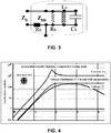
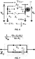
- a device for filtering the resonance peak of said at least one loudspeaker HP is incorporated either in the first GND.a instrumentation ground circuit or in the feedback loop, this device filtering being purely electrical in the form of an impedance, namely Z b shown in FIGS. figures 1 and 3 or Z 2 shown to Figures 6 and 7 .
- This impedance Z b or Z 2 is incorporated in the first GND.a instrumentation ground circuit, as shown in FIGS. figures 1 and 3 , or in the feedback loop, as shown in Figures 6 and 7 .
- the parameters of the impedance Z b or Z 2 are predetermined as a function of the resonance peak to be filtered from the at least one HP loudspeaker.
- the filtering device is located downstream of the loudspeaker HP in the two preferred embodiments which will be hereinafter detailed.
- the filtering device is incorporated in the first GND.a instrumentation ground circuit.
- the impedance Z b of the filtering device is in the form of a dead resistor R 0 associated with a first impedance called parallel RLC Z bb .
- This first impedance comprises at least a first resistor R b , at least a first inductance L b and at least a first capacitor C b arranged in parallel with each other, the first parallel RLC impedance Z bb being arranged in series with the dead resistor R 0 in said first instrumentation ground circuit.
- the figure 3 illustrates the elements leading to developing a resonance factor compensation using a parallel RLC filter arranged in series with a resistor R 0 .
- the filtering device is therefore incorporated in the first GND.a instrumentation ground circuit.
- the current I f flowing in the return loop of the converter may be equal to 0.
- the application of the criterion C 1 relating to the resonant frequency is to be considered as a function of the availability and the price of the two respective components: the inductor or inductors, advantageously coils wound on air and the bipolar capacitor or capacitors .
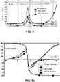
- the figure 4 illustrates the curves of the acceleration modules during current control with or without resonance peak filtering as well as during a voltage control of a loudspeaker, the filtering taking place with a filtering device according to the first embodiment of the invention.
- the intermediate curve is the curve with current control and filtering with a filtering device according to the first embodiment and shows the absence of a resonance peak unlike the upper curve with current control without filtering.
- the intermediate curve has a substantially constant acceleration module range wider than that of the lower curve which is the curve with voltage control.
- the second embodiment of the filtering device provides for its incorporation into the loop back of the inverter A 0 . This is shown to Figures 6 and 7 .
- the filtering device is incorporated in the feedback loop and is in the form of a second impedance Z 2 comprising a second resistor R 2 associated in parallel with at least a second inductance L 2 and at least one second capacitor C 2 , said at least a second inductor L 2 and said at least one second capacitor C 2 being arranged in series.
- the second embodiment avoids this disadvantage by choosing to arrange the filtering device in the loop back of the converter A 0 .
- the first and second circuits of instrumentation mass respectively incorporate a first dead resistor R B for the first instrumentation ground circuit GND.a and a second resistor R 3 for the second instrumentation ground circuit.
- the current I f returning to the negative pole of the converter after the derivation of the second instrumentation mass may be equal to 0.
- the calibration of the device can be made as a function of the value of the first dead resistor R B , the value of the second resistor R 2 of the second impedance Z 2 being determined as a function of the value of the first dead resistor R B being 10 to 100 times greater than the value of the first resistor R B , the value of the second resistor R 3 being 2 to 30 times greater than the value of the first resistor R B .
- the value of R B should not advantageously be too high to maintain the stability.
- the behaviors of the device filtering and transconductance are illustrated on the figure 8 .
- the phase plots underline the phase rotation presented by Z 2 as well as the symmetry observed by the transconductance compared with the transducer.
- E has a unit value.
- Gain or attenuation may allow adjustment, either by adding a stage upstream of the conditioner or by modifying the value of the resistor R B provided that it does not alter the stability as a function of the amplifier used.
- the exemplary loudspeaker has a moderate mechanical resonance factor Q m ⁇ 3 value sufficiently low to allow the correction envisaged.
- Q m the mechanical resonance factor
- the application of this correction is more demanding.
- this solution requires an inductance of 80 mH, a value that can be prohibitive for winding on air.
- An artificial self-assembly, particularly with gyratory devices, can however be envisaged, a variation of inductance can thus be easily obtained.
- the inductors serving as inductors in the various embodiments shown may be made of metals or light alloys other than copper, the main criterion being a good electrical conductivity.
- the figure 8 illustrates the current control curves with or without resonance peak filtering and the voltage control curve of a loudspeaker, the filtering taking place with a filtering device according to the second embodiment of the invention .
- the intermediate curve is the curve with current control and filtering with a filtering device according to the second embodiment and shows the absence of a resonance peak unlike the upper curve with current control without filtering.
- the intermediate curve has a substantially constant acceleration module range wider than that of the lower curve which is the curve with voltage control.
- the curves of the compared impedance modules of the filter device Z 2 and of the at least one loudspeaker Z HP have respectively been drawn respectively. These impedance module curves increase and decrease in opposition.
- the curve with rectangles illustrates the impedance curve Z 2 of the filtering device while the curve with circles illustrates the impedance curve Z HP of the loudspeaker
- At least one non-inverting converter has been used in the circuit, in order to simplify the calculations.
- This is not limiting and the present invention can also be applied for a circuit comprising a plurality of non-inverter converters as well as one or more inverters.
Landscapes
- Physics & Mathematics (AREA)
- Engineering & Computer Science (AREA)
- Acoustics & Sound (AREA)
- Signal Processing (AREA)
- Electromagnetism (AREA)
- Health & Medical Sciences (AREA)
- General Health & Medical Sciences (AREA)
- Otolaryngology (AREA)
- Circuit For Audible Band Transducer (AREA)
Claims (7)
- Schaltung zur Versorgung mit akustischen Signalen mindestens eines Lautsprechers (HP), die eine Filtervorrichtung der Resonanzspitze des mindestens einen Lautsprechers (HP) umfasst, die bei einer bestimmten Frequenz des Versorgungsstroms des mindestens einen Lautsprechers (HP) auftritt, wobei die Schaltung mindestens einen nicht umkehrenden Wandler (A0) umfasst, der stromaufwärts des mindestens einen Lautsprechers (HP) angeordnet ist, wobei der Wandler eine positive Versorgungsklemme aufweist, die mit der Eingangsversorgung der Schaltung verbunden ist, und eine negative Versorgungsklemme, wobei die Schaltung auch am Ausgang des mindestens einen Lautsprechers (HP) eine erste Instrumentenausrüstungsmasseschaltung (GND.a) stromabwärts des Lautsprechers in Abzweigung von einer Rücklaufschleife umfasst, die den Eingangspunkt der Masseschaltung stromabwärts des Lautsprechers (HP) mit der negativen Versorgungsklemme des nicht umkehrenden Wandlers (A0) verbindet, wobei die Filtervorrichtung der Resonanzspitze des mindestens einen Lautsprechers (HP) rein elektrisch in der Form einer Impedanz (Zb, Z2) ist, die entweder in der ersten Instrumentenausrüstungsmasseschaltung (GND.a) oder in der Rückkehrschleife eingebaut ist, wobei die Parameter der Impedanz (Zb, Z2) in Abhängigkeit von der zu filternden Resonanzspitze des mindestens einen Lautsprechers (HP) vorbestimmt sind, dadurch gekennzeichnet, dass:- wenn die Impedanz (Zb) in die erste Instrumentenausrüstungsmasseschaltung (GND.a) eingebaut ist, diese Impedanz (Zb) die Form eines reinen Widerstands (R0) aufweist, der mit einer ersten Impedanz, parallele RCL (Zbb) genannt, assoziiert ist, die mindestens einen ersten Widerstand (Rb), mindestens eine erste Induktanz (Lb) und mindestens einen ersten Kondensator (Cb) umfasst, die miteinander parallel geschaltet sind, wobei die erste parallele Impedanz RLC (Zbb) in Reihe mit dem reinen Widerstand (R0) in der ersten Instrumentenausrüstungsmasseschaltung (GND.a) angeordnet ist, und- wenn die Impedanz (Z2) in die Rückkehrschleife eingebaut ist, diese Impedanz als zweite Impedanz (Z2) einen zweiten Widerstand (R2) umfasst, der parallel mit mindestens einer zweiten Induktanz (L2) und mindestens einem zweiten Kondensator (C2) assoziiert ist, wobei die mindestens eine zweite Induktanz (L2) und der mindestens eine zweite Kondensator (C2) in Reihe angeordnet sind.
- Schaltung nach dem vorstehenden Anspruch, wobei, wenn die Impedanz (Zb) in die erste Instrumentenausrüstungsmasseschaltung (GND.a) eingebaut ist, die Werte des mindestens einen ersten Kondensators (Cb) des mindestens einen ersten Widerstands (Rb) und der mindestens einen ersten Induktanz (Lb) gemäß Parametern des mindestens einen Lautsprechers (HP) berechnet sind, nämlich dem Verhältnis fm/Mm, das für die Dämpfung des Verhältnisses km/Mm repräsentativ ist, das für das Verhältnis des Quadrats der Winkelresonanzfrequenz des mindestens einen Lautsprechers (HP) gemäß den folgenden Gleichungen repräsentativ ist:


- Schaltung nach dem vorstehenden Anspruch, wobei der Wert des reinen Widerstands (R0) gemäß der folgenden Gleichung berechnet wird:

- Schaltung nach einem der drei vorstehenden Ansprüche, wobei die erste parallele Impedanz RLC (Zbb) n erste Induktanzen (Lb) und n erste Kondensatoren (Cb) umfasst, wobei n größer oder gleich eins ist.
- Schaltung nach dem vorstehenden Anspruch wobei, wenn die Impedanz (Z2) in die Rückkehrschleife eingebaut ist, eine zweite Instrumentenausrüstungsmasseschaltung zwischen der zweiten Impedanz (Z2) und dem Wandler (A0) angeordnet ist, wobei die erste und die zweite Instrumentenausrüstungsmasseschaltung jeweils einen ersten reinen Widerstand (RB) für die erste Instrumentenausrüstungsmasseschaltung, und einen zweiten reinen Widerstand (R3) für die zweite Instrumentenausrüstungsmasseschaltung enthalten.
- Schaltung nach dem vorstehenden Anspruch, wobei ein Kalibrieren der Vorrichtung in Abhängigkeit von dem Wert des ersten reinen Widerstands (RB) ausgeführt wird, wobei der Wert des zweiten Widerstands (R2) der zweiten Impedanz (Z2) in Abhängigkeit von dem Wert des ersten reinen Widerstands (RB) bestimmt wird, wobei er 10 bis 100 Mal größer ist als der Wert des ersten reinen Widerstands (RB), wobei der Wert des zweiten reinen Widerstands (R3) 2 bis 30 Mal größer ist als der Wert des ersten reinen Widerstands (RB).
- Schaltung nach einem der Ansprüche 1, 5 oder 6, wobei, wenn der Wert der mindestens einen zweiten Induktanz (L2) einen Wert von 50 mH überschreitet, die mindestens eine zweite Induktanz (L2) die Form virtueller Drosselwiderstände, die mit Gyratormitteln versehen sind, aufweist.
Applications Claiming Priority (3)
| Application Number | Priority Date | Filing Date | Title |
|---|---|---|---|
| FR1400569A FR3018418B1 (fr) | 2014-03-04 | 2014-03-04 | Dispositif et procede de filtrage du pic de resonance dans un circuit d'alimentation d'au moins un haut-parleur |
| PCT/FR2015/000048 WO2015132486A1 (fr) | 2014-03-04 | 2015-03-03 | Dispositif et procédé de filtrage du pic de résonance dans un circuit d'alimentation d'au moins un haut-parleur |
| EP15714245.6A EP3114855A1 (de) | 2014-03-04 | 2015-03-03 | Vorrichtung und verfahren zur filtrierung der resonanzspitze in einer schaltung zur versorgung von mindestens einem lautsprecher |
Related Parent Applications (1)
| Application Number | Title | Priority Date | Filing Date |
|---|---|---|---|
| EP15714245.6A Division EP3114855A1 (de) | 2014-03-04 | 2015-03-03 | Vorrichtung und verfahren zur filtrierung der resonanzspitze in einer schaltung zur versorgung von mindestens einem lautsprecher |
Publications (2)
| Publication Number | Publication Date |
|---|---|
| EP3249949A1 EP3249949A1 (de) | 2017-11-29 |
| EP3249949B1 true EP3249949B1 (de) | 2019-09-04 |
Family
ID=51483454
Family Applications (2)
| Application Number | Title | Priority Date | Filing Date |
|---|---|---|---|
| EP17156045.1A Active EP3249949B1 (de) | 2014-03-04 | 2015-03-03 | Vorrichtung und verfahren zur filterung der resonanz-spitze in der stromversorgung von mindestens einem lautsprecher |
| EP15714245.6A Pending EP3114855A1 (de) | 2014-03-04 | 2015-03-03 | Vorrichtung und verfahren zur filtrierung der resonanzspitze in einer schaltung zur versorgung von mindestens einem lautsprecher |
Family Applications After (1)
| Application Number | Title | Priority Date | Filing Date |
|---|---|---|---|
| EP15714245.6A Pending EP3114855A1 (de) | 2014-03-04 | 2015-03-03 | Vorrichtung und verfahren zur filtrierung der resonanzspitze in einer schaltung zur versorgung von mindestens einem lautsprecher |
Country Status (6)
| Country | Link |
|---|---|
| US (1) | US10212515B2 (de) |
| EP (2) | EP3249949B1 (de) |
| JP (1) | JP6374976B2 (de) |
| CN (1) | CN106105260B (de) |
| FR (1) | FR3018418B1 (de) |
| WO (1) | WO2015132486A1 (de) |
Families Citing this family (3)
| Publication number | Priority date | Publication date | Assignee | Title |
|---|---|---|---|---|
| CN109218952B (zh) * | 2018-08-08 | 2020-12-22 | 厦门傅里叶电子有限公司 | 基于相位变化测量的喇叭温度测试系统及方法 |
| CN110473509B (zh) * | 2019-08-19 | 2021-11-12 | 深圳南云微电子有限公司 | 一种峰值电流型蜂鸣器驱动电路 |
| FR3132404B1 (fr) | 2022-02-03 | 2024-05-10 | Centre Nat Rech Scient | Ensemble aimant de moteur de haut-parleur électrodynamique, moteur de haut-parleur électrodynamique le comprenant, et haut-parleur électrodynamique associé |
Family Cites Families (11)
| Publication number | Priority date | Publication date | Assignee | Title |
|---|---|---|---|---|
| FR2422309A1 (fr) | 1978-04-04 | 1979-11-02 | Daniere Joannes | Systeme pour la reproduction de signaux acoustiques de frequences tres basses jusqu'aux plus elevees |
| JPS56103592A (en) * | 1980-01-23 | 1981-08-18 | Hitachi Ltd | Speaker driving system |
| JPS5735159A (en) * | 1980-08-12 | 1982-02-25 | Hitachi Ltd | Knock control system |
| JPS59143138U (ja) * | 1983-03-14 | 1984-09-25 | 日本ビクター株式会社 | 中間周波増幅回路における群遅延時間補正回路 |
| DE3836745A1 (de) * | 1988-10-28 | 1990-05-03 | Standard Elektrik Lorenz Ag | Verfahren und vorrichtung zur linearisierung des frequenzganges eines lautsprechersystems |
| US6654468B1 (en) * | 1998-08-25 | 2003-11-25 | Knowles Electronics, Llc | Apparatus and method for matching the response of microphones in magnitude and phase |
| JP2007028419A (ja) * | 2005-07-20 | 2007-02-01 | Victor Co Of Japan Ltd | スピーカ駆動装置 |
| JP4793174B2 (ja) * | 2005-11-25 | 2011-10-12 | セイコーエプソン株式会社 | 静電型トランスデューサ、回路定数の設定方法 |
| FI122088B (fi) * | 2009-09-25 | 2011-08-15 | Esa Merilaeinen | Nousevan taajuusvasteen kompensointi virtaohjatussa passiivikaiuttimessa |
| EP2348750B1 (de) * | 2010-01-25 | 2012-09-12 | Nxp B.V. | Steuerung einer Lautsprecherausgabe |
| US9113257B2 (en) * | 2013-02-01 | 2015-08-18 | William E. Collins | Phase-unified loudspeakers: parallel crossovers |
-
2014
- 2014-03-04 FR FR1400569A patent/FR3018418B1/fr not_active Expired - Fee Related
-
2015
- 2015-03-03 CN CN201580011353.4A patent/CN106105260B/zh not_active Expired - Fee Related
- 2015-03-03 JP JP2016554732A patent/JP6374976B2/ja not_active Expired - Fee Related
- 2015-03-03 US US15/127,884 patent/US10212515B2/en not_active Expired - Fee Related
- 2015-03-03 EP EP17156045.1A patent/EP3249949B1/de active Active
- 2015-03-03 WO PCT/FR2015/000048 patent/WO2015132486A1/fr not_active Ceased
- 2015-03-03 EP EP15714245.6A patent/EP3114855A1/de active Pending
Non-Patent Citations (1)
| Title |
|---|
| None * |
Also Published As
| Publication number | Publication date |
|---|---|
| US20170303038A1 (en) | 2017-10-19 |
| EP3249949A1 (de) | 2017-11-29 |
| US10212515B2 (en) | 2019-02-19 |
| FR3018418A1 (fr) | 2015-09-11 |
| JP6374976B2 (ja) | 2018-08-15 |
| CN106105260A (zh) | 2016-11-09 |
| JP2017512024A (ja) | 2017-04-27 |
| CN106105260B (zh) | 2019-08-16 |
| WO2015132486A1 (fr) | 2015-09-11 |
| EP3114855A1 (de) | 2017-01-11 |
| FR3018418B1 (fr) | 2017-11-10 |
Similar Documents
| Publication | Publication Date | Title |
|---|---|---|
| EP3111668B1 (de) | Vorrichtung zur steuerung eines lautsprechers | |
| EP3111669B1 (de) | Vorrichtung zur steuerung eines lautsprechers | |
| WO2015140421A1 (fr) | Dispositif et procédé de filtrage du pic de résonance dans un circuit d'alimentation d'au moins un haut-parleur en amont de celui-ci | |
| EP2717599B1 (de) | Verfahren zur Audiosignalverarbeitung mit Modellierung der globalen Antwort des elektrodynamischen Lautsprechers | |
| EP2726832B1 (de) | Resistive vorrichtung mit einem silicium-nanodraht-dehnungsmessstreifen und verfahren zur optimierung des stromverbrauchs einer solchen vorrichtung | |
| WO2010136661A1 (fr) | Procede et dispositif d'attenuation d'un bruit a bande etroite dans un habitacle d'un vehicule | |
| FR2947398A1 (fr) | Dispositif resonant a ondes acoustiques guidees et procede de realisation du dispositif | |
| EP3248285B1 (de) | Vorrichtung zur steuerung eines lautsprechers mit strombegrenzung | |
| EP3249949A1 (de) | Vorrichtung und verfahren zur filterung der resonanz-spitze in der stromversorgung von mindestens einem lautsprecher | |
| FR2562353A1 (fr) | Dispositif electro-acoustique | |
| EP3637792B1 (de) | Steuerungsvorrichtung eines lautsprechers und entsprechende klangwiedergabeanlage | |
| EP4127737B1 (de) | Schneller und spannungsdriftunempfindlicher rogowski-stromsensor | |
| EP4493942B1 (de) | Magnetfeldsensor zur messung eines gleichstroms | |
| EP4127736A2 (de) | Stromsensor mit sehr grosser bandbreite | |
| WO2014072362A1 (fr) | Recepteur d'un signal lumineux impulsionnel a forte dynamique | |
| WO2020249622A1 (fr) | Systeme d'amortissement des vibrations generees par un dispositif et procede associe | |
| WO2020053107A1 (fr) | Emulateur de pickups à base d' un pickup magnétique pour instrument de musique a cordes | |
| EP4055395B1 (de) | Stromdetektor, zugehöriger sensor, system und verfahren | |
| Hong et al. | A two-tone test method for continuous-time adaptive equalizers | |
| EP1947366A1 (de) | System, das die mechanische Schwingungsübertragung durch Frequenzfilterung begrenzt | |
| FR3115176A1 (fr) | Dispositif de traitement d’un signal analogique, systeme audio et porte sonorisee de vehicule associes | |
| WO1999059377A1 (fr) | Dispositif de controle actif d'impedance acoustique | |
| FR2824914A1 (fr) | Equipement et procede du mesure de l'acceleration vibratoire radiale instantanee | |
| WO2010109138A1 (fr) | Dispositif pour detecter et/ou mesurer un champ magnetique faible | |
| BE554295A (de) |
Legal Events
| Date | Code | Title | Description |
|---|---|---|---|
| STAA | Information on the status of an ep patent application or granted ep patent |
Free format text: STATUS: UNKNOWN |
|
| PUAI | Public reference made under article 153(3) epc to a published international application that has entered the european phase |
Free format text: ORIGINAL CODE: 0009012 |
|
| STAA | Information on the status of an ep patent application or granted ep patent |
Free format text: STATUS: THE APPLICATION HAS BEEN PUBLISHED |
|
| AC | Divisional application: reference to earlier application |
Ref document number: 3114855 Country of ref document: EP Kind code of ref document: P |
|
| AK | Designated contracting states |
Kind code of ref document: A1 Designated state(s): AL AT BE BG CH CY CZ DE DK EE ES FI FR GB GR HR HU IE IS IT LI LT LU LV MC MK MT NL NO PL PT RO RS SE SI SK SM TR |
|
| AX | Request for extension of the european patent |
Extension state: BA ME |
|
| STAA | Information on the status of an ep patent application or granted ep patent |
Free format text: STATUS: REQUEST FOR EXAMINATION WAS MADE |
|
| 17P | Request for examination filed |
Effective date: 20180528 |
|
| RBV | Designated contracting states (corrected) |
Designated state(s): AL AT BE BG CH CY CZ DE DK EE ES FI FR GB GR HR HU IE IS IT LI LT LU LV MC MK MT NL NO PL PT RO RS SE SI SK SM TR |
|
| REG | Reference to a national code |
Ref country code: DE Ref legal event code: R079 Ref document number: 602015037574 Country of ref document: DE Free format text: PREVIOUS MAIN CLASS: H04R0003080000 Ipc: H04R0003000000 |
|
| STAA | Information on the status of an ep patent application or granted ep patent |
Free format text: STATUS: EXAMINATION IS IN PROGRESS |
|
| RIC1 | Information provided on ipc code assigned before grant |
Ipc: H04R 3/08 20060101ALI20180821BHEP Ipc: H04R 3/02 20060101ALI20180821BHEP Ipc: H04R 3/00 20060101AFI20180821BHEP |
|
| 17Q | First examination report despatched |
Effective date: 20180911 |
|
| GRAP | Despatch of communication of intention to grant a patent |
Free format text: ORIGINAL CODE: EPIDOSNIGR1 |
|
| STAA | Information on the status of an ep patent application or granted ep patent |
Free format text: STATUS: GRANT OF PATENT IS INTENDED |
|
| INTG | Intention to grant announced |
Effective date: 20190408 |
|
| GRAS | Grant fee paid |
Free format text: ORIGINAL CODE: EPIDOSNIGR3 |
|
| GRAA | (expected) grant |
Free format text: ORIGINAL CODE: 0009210 |
|
| STAA | Information on the status of an ep patent application or granted ep patent |
Free format text: STATUS: THE PATENT HAS BEEN GRANTED |
|
| AC | Divisional application: reference to earlier application |
Ref document number: 3114855 Country of ref document: EP Kind code of ref document: P |
|
| AK | Designated contracting states |
Kind code of ref document: B1 Designated state(s): AL AT BE BG CH CY CZ DE DK EE ES FI FR GB GR HR HU IE IS IT LI LT LU LV MC MK MT NL NO PL PT RO RS SE SI SK SM TR |
|
| REG | Reference to a national code |
Ref country code: GB Ref legal event code: FG4D Free format text: NOT ENGLISH |
|
| REG | Reference to a national code |
Ref country code: CH Ref legal event code: EP |
|
| REG | Reference to a national code |
Ref country code: AT Ref legal event code: REF Ref document number: 1177091 Country of ref document: AT Kind code of ref document: T Effective date: 20190915 |
|
| REG | Reference to a national code |
Ref country code: DE Ref legal event code: R096 Ref document number: 602015037574 Country of ref document: DE |
|
| REG | Reference to a national code |
Ref country code: IE Ref legal event code: FG4D Free format text: LANGUAGE OF EP DOCUMENT: FRENCH |
|
| REG | Reference to a national code |
Ref country code: DE Ref legal event code: R082 Ref document number: 602015037574 Country of ref document: DE Representative=s name: ADVOPAT PATENT- UND RECHTSANWAELTE, DE Ref country code: DE Ref legal event code: R081 Ref document number: 602015037574 Country of ref document: DE Owner name: CENTRE NATIONAL DE LA RECHERCHE SCIENTIFIQUE (, FR Free format text: FORMER OWNERS: CENTRE NATIONAL DE LA RECHERCHE SCIENTIFIQUE (CNRS), PARIS, FR; UNIVERSITE DU MAINE, LE MANS, FR; WHYLOT SAS, CAMBES, FR Ref country code: DE Ref legal event code: R081 Ref document number: 602015037574 Country of ref document: DE Owner name: UNIVERSITE DU MANS, FR Free format text: FORMER OWNERS: CENTRE NATIONAL DE LA RECHERCHE SCIENTIFIQUE (CNRS), PARIS, FR; UNIVERSITE DU MAINE, LE MANS, FR; WHYLOT SAS, CAMBES, FR |
|
| RAP2 | Party data changed (patent owner data changed or rights of a patent transferred) |
Owner name: CENTRE NATIONAL DE LA RECHERCHE SCIENTIFIQUE (CNRS Owner name: UNIVERSITE DU MANS |
|
| REG | Reference to a national code |
Ref country code: NL Ref legal event code: MP Effective date: 20190904 |
|
| REG | Reference to a national code |
Ref country code: LT Ref legal event code: MG4D |
|
| PG25 | Lapsed in a contracting state [announced via postgrant information from national office to epo] |
Ref country code: SE Free format text: LAPSE BECAUSE OF FAILURE TO SUBMIT A TRANSLATION OF THE DESCRIPTION OR TO PAY THE FEE WITHIN THE PRESCRIBED TIME-LIMIT Effective date: 20190904 Ref country code: NO Free format text: LAPSE BECAUSE OF FAILURE TO SUBMIT A TRANSLATION OF THE DESCRIPTION OR TO PAY THE FEE WITHIN THE PRESCRIBED TIME-LIMIT Effective date: 20191204 Ref country code: HR Free format text: LAPSE BECAUSE OF FAILURE TO SUBMIT A TRANSLATION OF THE DESCRIPTION OR TO PAY THE FEE WITHIN THE PRESCRIBED TIME-LIMIT Effective date: 20190904 Ref country code: FI Free format text: LAPSE BECAUSE OF FAILURE TO SUBMIT A TRANSLATION OF THE DESCRIPTION OR TO PAY THE FEE WITHIN THE PRESCRIBED TIME-LIMIT Effective date: 20190904 Ref country code: LT Free format text: LAPSE BECAUSE OF FAILURE TO SUBMIT A TRANSLATION OF THE DESCRIPTION OR TO PAY THE FEE WITHIN THE PRESCRIBED TIME-LIMIT Effective date: 20190904 Ref country code: BG Free format text: LAPSE BECAUSE OF FAILURE TO SUBMIT A TRANSLATION OF THE DESCRIPTION OR TO PAY THE FEE WITHIN THE PRESCRIBED TIME-LIMIT Effective date: 20191204 |
|
| PG25 | Lapsed in a contracting state [announced via postgrant information from national office to epo] |
Ref country code: LV Free format text: LAPSE BECAUSE OF FAILURE TO SUBMIT A TRANSLATION OF THE DESCRIPTION OR TO PAY THE FEE WITHIN THE PRESCRIBED TIME-LIMIT Effective date: 20190904 Ref country code: ES Free format text: LAPSE BECAUSE OF FAILURE TO SUBMIT A TRANSLATION OF THE DESCRIPTION OR TO PAY THE FEE WITHIN THE PRESCRIBED TIME-LIMIT Effective date: 20190904 Ref country code: RS Free format text: LAPSE BECAUSE OF FAILURE TO SUBMIT A TRANSLATION OF THE DESCRIPTION OR TO PAY THE FEE WITHIN THE PRESCRIBED TIME-LIMIT Effective date: 20190904 Ref country code: GR Free format text: LAPSE BECAUSE OF FAILURE TO SUBMIT A TRANSLATION OF THE DESCRIPTION OR TO PAY THE FEE WITHIN THE PRESCRIBED TIME-LIMIT Effective date: 20191205 Ref country code: AL Free format text: LAPSE BECAUSE OF FAILURE TO SUBMIT A TRANSLATION OF THE DESCRIPTION OR TO PAY THE FEE WITHIN THE PRESCRIBED TIME-LIMIT Effective date: 20190904 |
|
| REG | Reference to a national code |
Ref country code: AT Ref legal event code: MK05 Ref document number: 1177091 Country of ref document: AT Kind code of ref document: T Effective date: 20190904 |
|
| PG25 | Lapsed in a contracting state [announced via postgrant information from national office to epo] |
Ref country code: NL Free format text: LAPSE BECAUSE OF FAILURE TO SUBMIT A TRANSLATION OF THE DESCRIPTION OR TO PAY THE FEE WITHIN THE PRESCRIBED TIME-LIMIT Effective date: 20190904 Ref country code: PL Free format text: LAPSE BECAUSE OF FAILURE TO SUBMIT A TRANSLATION OF THE DESCRIPTION OR TO PAY THE FEE WITHIN THE PRESCRIBED TIME-LIMIT Effective date: 20190904 Ref country code: PT Free format text: LAPSE BECAUSE OF FAILURE TO SUBMIT A TRANSLATION OF THE DESCRIPTION OR TO PAY THE FEE WITHIN THE PRESCRIBED TIME-LIMIT Effective date: 20200106 Ref country code: RO Free format text: LAPSE BECAUSE OF FAILURE TO SUBMIT A TRANSLATION OF THE DESCRIPTION OR TO PAY THE FEE WITHIN THE PRESCRIBED TIME-LIMIT Effective date: 20190904 Ref country code: EE Free format text: LAPSE BECAUSE OF FAILURE TO SUBMIT A TRANSLATION OF THE DESCRIPTION OR TO PAY THE FEE WITHIN THE PRESCRIBED TIME-LIMIT Effective date: 20190904 Ref country code: IT Free format text: LAPSE BECAUSE OF FAILURE TO SUBMIT A TRANSLATION OF THE DESCRIPTION OR TO PAY THE FEE WITHIN THE PRESCRIBED TIME-LIMIT Effective date: 20190904 Ref country code: AT Free format text: LAPSE BECAUSE OF FAILURE TO SUBMIT A TRANSLATION OF THE DESCRIPTION OR TO PAY THE FEE WITHIN THE PRESCRIBED TIME-LIMIT Effective date: 20190904 |
|
| PG25 | Lapsed in a contracting state [announced via postgrant information from national office to epo] |
Ref country code: IS Free format text: LAPSE BECAUSE OF FAILURE TO SUBMIT A TRANSLATION OF THE DESCRIPTION OR TO PAY THE FEE WITHIN THE PRESCRIBED TIME-LIMIT Effective date: 20200224 Ref country code: SM Free format text: LAPSE BECAUSE OF FAILURE TO SUBMIT A TRANSLATION OF THE DESCRIPTION OR TO PAY THE FEE WITHIN THE PRESCRIBED TIME-LIMIT Effective date: 20190904 Ref country code: CZ Free format text: LAPSE BECAUSE OF FAILURE TO SUBMIT A TRANSLATION OF THE DESCRIPTION OR TO PAY THE FEE WITHIN THE PRESCRIBED TIME-LIMIT Effective date: 20190904 Ref country code: SK Free format text: LAPSE BECAUSE OF FAILURE TO SUBMIT A TRANSLATION OF THE DESCRIPTION OR TO PAY THE FEE WITHIN THE PRESCRIBED TIME-LIMIT Effective date: 20190904 |
|
| REG | Reference to a national code |
Ref country code: DE Ref legal event code: R097 Ref document number: 602015037574 Country of ref document: DE |
|
| PLBE | No opposition filed within time limit |
Free format text: ORIGINAL CODE: 0009261 |
|
| STAA | Information on the status of an ep patent application or granted ep patent |
Free format text: STATUS: NO OPPOSITION FILED WITHIN TIME LIMIT |
|
| PG2D | Information on lapse in contracting state deleted |
Ref country code: IS |
|
| PG25 | Lapsed in a contracting state [announced via postgrant information from national office to epo] |
Ref country code: DK Free format text: LAPSE BECAUSE OF FAILURE TO SUBMIT A TRANSLATION OF THE DESCRIPTION OR TO PAY THE FEE WITHIN THE PRESCRIBED TIME-LIMIT Effective date: 20190904 Ref country code: IS Free format text: LAPSE BECAUSE OF FAILURE TO SUBMIT A TRANSLATION OF THE DESCRIPTION OR TO PAY THE FEE WITHIN THE PRESCRIBED TIME-LIMIT Effective date: 20200105 |
|
| 26N | No opposition filed |
Effective date: 20200605 |
|
| PG25 | Lapsed in a contracting state [announced via postgrant information from national office to epo] |
Ref country code: SI Free format text: LAPSE BECAUSE OF FAILURE TO SUBMIT A TRANSLATION OF THE DESCRIPTION OR TO PAY THE FEE WITHIN THE PRESCRIBED TIME-LIMIT Effective date: 20190904 |
|
| PG25 | Lapsed in a contracting state [announced via postgrant information from national office to epo] |
Ref country code: MC Free format text: LAPSE BECAUSE OF FAILURE TO SUBMIT A TRANSLATION OF THE DESCRIPTION OR TO PAY THE FEE WITHIN THE PRESCRIBED TIME-LIMIT Effective date: 20190904 |
|
| REG | Reference to a national code |
Ref country code: BE Ref legal event code: MM Effective date: 20200331 |
|
| PG25 | Lapsed in a contracting state [announced via postgrant information from national office to epo] |
Ref country code: LU Free format text: LAPSE BECAUSE OF NON-PAYMENT OF DUE FEES Effective date: 20200303 |
|
| PG25 | Lapsed in a contracting state [announced via postgrant information from national office to epo] |
Ref country code: IE Free format text: LAPSE BECAUSE OF NON-PAYMENT OF DUE FEES Effective date: 20200303 |
|
| PG25 | Lapsed in a contracting state [announced via postgrant information from national office to epo] |
Ref country code: BE Free format text: LAPSE BECAUSE OF NON-PAYMENT OF DUE FEES Effective date: 20200331 |
|
| GBPC | Gb: european patent ceased through non-payment of renewal fee |
Effective date: 20200303 |
|
| PG25 | Lapsed in a contracting state [announced via postgrant information from national office to epo] |
Ref country code: GB Free format text: LAPSE BECAUSE OF NON-PAYMENT OF DUE FEES Effective date: 20200303 |
|
| PGFP | Annual fee paid to national office [announced via postgrant information from national office to epo] |
Ref country code: CH Payment date: 20210322 Year of fee payment: 7 Ref country code: FR Payment date: 20210330 Year of fee payment: 7 |
|
| PGFP | Annual fee paid to national office [announced via postgrant information from national office to epo] |
Ref country code: DE Payment date: 20210310 Year of fee payment: 7 |
|
| PG25 | Lapsed in a contracting state [announced via postgrant information from national office to epo] |
Ref country code: TR Free format text: LAPSE BECAUSE OF FAILURE TO SUBMIT A TRANSLATION OF THE DESCRIPTION OR TO PAY THE FEE WITHIN THE PRESCRIBED TIME-LIMIT Effective date: 20190904 Ref country code: MT Free format text: LAPSE BECAUSE OF FAILURE TO SUBMIT A TRANSLATION OF THE DESCRIPTION OR TO PAY THE FEE WITHIN THE PRESCRIBED TIME-LIMIT Effective date: 20190904 Ref country code: CY Free format text: LAPSE BECAUSE OF FAILURE TO SUBMIT A TRANSLATION OF THE DESCRIPTION OR TO PAY THE FEE WITHIN THE PRESCRIBED TIME-LIMIT Effective date: 20190904 |
|
| PG25 | Lapsed in a contracting state [announced via postgrant information from national office to epo] |
Ref country code: MK Free format text: LAPSE BECAUSE OF FAILURE TO SUBMIT A TRANSLATION OF THE DESCRIPTION OR TO PAY THE FEE WITHIN THE PRESCRIBED TIME-LIMIT Effective date: 20190904 |
|
| REG | Reference to a national code |
Ref country code: DE Ref legal event code: R119 Ref document number: 602015037574 Country of ref document: DE |
|
| REG | Reference to a national code |
Ref country code: CH Ref legal event code: PL |
|
| PG25 | Lapsed in a contracting state [announced via postgrant information from national office to epo] |
Ref country code: LI Free format text: LAPSE BECAUSE OF NON-PAYMENT OF DUE FEES Effective date: 20220331 Ref country code: FR Free format text: LAPSE BECAUSE OF NON-PAYMENT OF DUE FEES Effective date: 20220331 Ref country code: DE Free format text: LAPSE BECAUSE OF NON-PAYMENT OF DUE FEES Effective date: 20221001 Ref country code: CH Free format text: LAPSE BECAUSE OF NON-PAYMENT OF DUE FEES Effective date: 20220331 |