EP3250340B1 - Spindelanordnung - Google Patents
Spindelanordnung Download PDFInfo
- Publication number
- EP3250340B1 EP3250340B1 EP16702372.0A EP16702372A EP3250340B1 EP 3250340 B1 EP3250340 B1 EP 3250340B1 EP 16702372 A EP16702372 A EP 16702372A EP 3250340 B1 EP3250340 B1 EP 3250340B1
- Authority
- EP
- European Patent Office
- Prior art keywords
- spindle
- actuator
- arrangement according
- vibration
- tool
- Prior art date
- Legal status (The legal status is an assumption and is not a legal conclusion. Google has not performed a legal analysis and makes no representation as to the accuracy of the status listed.)
- Active
Links
Images




Classifications
-
- B—PERFORMING OPERATIONS; TRANSPORTING
- B23—MACHINE TOOLS; METAL-WORKING NOT OTHERWISE PROVIDED FOR
- B23Q—DETAILS, COMPONENTS, OR ACCESSORIES FOR MACHINE TOOLS, e.g. ARRANGEMENTS FOR COPYING OR CONTROLLING; MACHINE TOOLS IN GENERAL CHARACTERISED BY THE CONSTRUCTION OF PARTICULAR DETAILS OR COMPONENTS; COMBINATIONS OR ASSOCIATIONS OF METAL-WORKING MACHINES, NOT DIRECTED TO A PARTICULAR RESULT
- B23Q11/00—Accessories fitted to machine tools for keeping tools or parts of the machine in good working condition or for cooling work; Safety devices specially combined with or arranged in, or specially adapted for use in connection with, machine tools
- B23Q11/0032—Arrangements for preventing or isolating vibrations in parts of the machine
- B23Q11/0039—Arrangements for preventing or isolating vibrations in parts of the machine by changing the natural frequency of the system or by continuously changing the frequency of the force which causes the vibration
-
- B—PERFORMING OPERATIONS; TRANSPORTING
- B06—GENERATING OR TRANSMITTING MECHANICAL VIBRATIONS IN GENERAL
- B06B—METHODS OR APPARATUS FOR GENERATING OR TRANSMITTING MECHANICAL VIBRATIONS OF INFRASONIC, SONIC, OR ULTRASONIC FREQUENCY, e.g. FOR PERFORMING MECHANICAL WORK IN GENERAL
- B06B3/00—Methods or apparatus specially adapted for transmitting mechanical vibrations of infrasonic, sonic, or ultrasonic frequency
-
- B—PERFORMING OPERATIONS; TRANSPORTING
- B23—MACHINE TOOLS; METAL-WORKING NOT OTHERWISE PROVIDED FOR
- B23Q—DETAILS, COMPONENTS, OR ACCESSORIES FOR MACHINE TOOLS, e.g. ARRANGEMENTS FOR COPYING OR CONTROLLING; MACHINE TOOLS IN GENERAL CHARACTERISED BY THE CONSTRUCTION OF PARTICULAR DETAILS OR COMPONENTS; COMBINATIONS OR ASSOCIATIONS OF METAL-WORKING MACHINES, NOT DIRECTED TO A PARTICULAR RESULT
- B23Q1/00—Members which are comprised in the general build-up of a form of machine, particularly relatively large fixed members
- B23Q1/25—Movable or adjustable work or tool supports
- B23Q1/44—Movable or adjustable work or tool supports using particular mechanisms
- B23Q1/48—Movable or adjustable work or tool supports using particular mechanisms with sliding pairs and rotating pairs
- B23Q1/4876—Movable or adjustable work or tool supports using particular mechanisms with sliding pairs and rotating pairs a single sliding pair followed parallelly by a single rotating pair
-
- B—PERFORMING OPERATIONS; TRANSPORTING
- B23—MACHINE TOOLS; METAL-WORKING NOT OTHERWISE PROVIDED FOR
- B23Q—DETAILS, COMPONENTS, OR ACCESSORIES FOR MACHINE TOOLS, e.g. ARRANGEMENTS FOR COPYING OR CONTROLLING; MACHINE TOOLS IN GENERAL CHARACTERISED BY THE CONSTRUCTION OF PARTICULAR DETAILS OR COMPONENTS; COMBINATIONS OR ASSOCIATIONS OF METAL-WORKING MACHINES, NOT DIRECTED TO A PARTICULAR RESULT
- B23Q11/00—Accessories fitted to machine tools for keeping tools or parts of the machine in good working condition or for cooling work; Safety devices specially combined with or arranged in, or specially adapted for use in connection with, machine tools
- B23Q11/0032—Arrangements for preventing or isolating vibrations in parts of the machine
- B23Q11/0035—Arrangements for preventing or isolating vibrations in parts of the machine by adding or adjusting a mass, e.g. counterweights
-
- B—PERFORMING OPERATIONS; TRANSPORTING
- B23—MACHINE TOOLS; METAL-WORKING NOT OTHERWISE PROVIDED FOR
- B23Q—DETAILS, COMPONENTS, OR ACCESSORIES FOR MACHINE TOOLS, e.g. ARRANGEMENTS FOR COPYING OR CONTROLLING; MACHINE TOOLS IN GENERAL CHARACTERISED BY THE CONSTRUCTION OF PARTICULAR DETAILS OR COMPONENTS; COMBINATIONS OR ASSOCIATIONS OF METAL-WORKING MACHINES, NOT DIRECTED TO A PARTICULAR RESULT
- B23Q5/00—Driving or feeding mechanisms; Control arrangements therefor
- B23Q5/02—Driving main working members
- B23Q5/027—Driving main working members reciprocating members
-
- B—PERFORMING OPERATIONS; TRANSPORTING
- B23—MACHINE TOOLS; METAL-WORKING NOT OTHERWISE PROVIDED FOR
- B23Q—DETAILS, COMPONENTS, OR ACCESSORIES FOR MACHINE TOOLS, e.g. ARRANGEMENTS FOR COPYING OR CONTROLLING; MACHINE TOOLS IN GENERAL CHARACTERISED BY THE CONSTRUCTION OF PARTICULAR DETAILS OR COMPONENTS; COMBINATIONS OR ASSOCIATIONS OF METAL-WORKING MACHINES, NOT DIRECTED TO A PARTICULAR RESULT
- B23Q5/00—Driving or feeding mechanisms; Control arrangements therefor
- B23Q5/02—Driving main working members
- B23Q5/04—Driving main working members rotary shafts, e.g. working-spindles
- B23Q5/10—Driving main working members rotary shafts, e.g. working-spindles driven essentially by electrical means
-
- B—PERFORMING OPERATIONS; TRANSPORTING
- B23—MACHINE TOOLS; METAL-WORKING NOT OTHERWISE PROVIDED FOR
- B23Q—DETAILS, COMPONENTS, OR ACCESSORIES FOR MACHINE TOOLS, e.g. ARRANGEMENTS FOR COPYING OR CONTROLLING; MACHINE TOOLS IN GENERAL CHARACTERISED BY THE CONSTRUCTION OF PARTICULAR DETAILS OR COMPONENTS; COMBINATIONS OR ASSOCIATIONS OF METAL-WORKING MACHINES, NOT DIRECTED TO A PARTICULAR RESULT
- B23Q2220/00—Machine tool components
- B23Q2220/006—Spindle heads
-
- B—PERFORMING OPERATIONS; TRANSPORTING
- B23—MACHINE TOOLS; METAL-WORKING NOT OTHERWISE PROVIDED FOR
- B23Q—DETAILS, COMPONENTS, OR ACCESSORIES FOR MACHINE TOOLS, e.g. ARRANGEMENTS FOR COPYING OR CONTROLLING; MACHINE TOOLS IN GENERAL CHARACTERISED BY THE CONSTRUCTION OF PARTICULAR DETAILS OR COMPONENTS; COMBINATIONS OR ASSOCIATIONS OF METAL-WORKING MACHINES, NOT DIRECTED TO A PARTICULAR RESULT
- B23Q2230/00—Special operations in a machine tool
- B23Q2230/004—Using a cutting tool reciprocating at high speeds, e.g. "fast tool"
-
- B—PERFORMING OPERATIONS; TRANSPORTING
- B23—MACHINE TOOLS; METAL-WORKING NOT OTHERWISE PROVIDED FOR
- B23Q—DETAILS, COMPONENTS, OR ACCESSORIES FOR MACHINE TOOLS, e.g. ARRANGEMENTS FOR COPYING OR CONTROLLING; MACHINE TOOLS IN GENERAL CHARACTERISED BY THE CONSTRUCTION OF PARTICULAR DETAILS OR COMPONENTS; COMBINATIONS OR ASSOCIATIONS OF METAL-WORKING MACHINES, NOT DIRECTED TO A PARTICULAR RESULT
- B23Q2705/00—Driving working spindles or feeding members carrying tools or work
- B23Q2705/02—Driving working spindles
Definitions
- the invention relates to a spindle arrangement for a machine tool according to the preamble of claim 1 (see e.g. WO 2013/142890 A1 ).
- Such spindle arrangements are used for the vibration-supporting machining of workpieces and in most cases work in the high-frequency range of several kHz, the vibration amplitudes being in the range of a few micrometers.
- increased productivity can generally be achieved through improved chip breaking as well as improved chip removal and a longer tool life through improved cooling lubricant supply.
- the vibration-superimposed production enables the machining of difficult-to-machine materials using standard tools. Such machining is conventionally only possible with special tools.
- the vibrations are coupled in either on the tool side or on the workpiece side.
- a hybrid machining of workpieces in which a tool for machining a workpiece is designed with an oscillating device via which the tool cutting edge can be subjected to an oscillation in a frequency range below the ultrasound.
- the oscillating device is designed with a balancing mass that oscillates in the opposite direction to the oscillation of the tool cutting edge, so that impulses are decoupled and the desired machining frequency can thus be set independently of the natural frequency of the device.
- the DE 10 2005 052 721 A1 shows a device for the vibration-assisted machining of workpieces, in which a spindle can be made to vibrate in the Z direction by means of a mechanical cam drive.
- vibrations can be introduced into the machine structure of the machine tool as a result of the back and forth movement of the spindle.
- the force components introduced into the machine structure via such vibrations can lead to defects and failures.
- the vibrations reduce the path accuracy of the machine and thus increase the positioning error around the axis of movement.
- the WO 93/25352 A1 discloses a hand machine tool with a compensation device for vibration compensation.
- the invention is based on the object of creating a spindle arrangement for a machine tool with which the machining accuracy is improved.
- the spindle arrangement for a machine tool has a tool spindle for driving a tool and an actuator or an actuator arrangement for exciting this tool or the tool spindle to vibrate.
- the spindle arrangement is designed with a compensation device for at least partial compensation of the inertial forces generated by the vibration excitation in the spindle area.
- a ring-shaped compensating mass which is in operative connection with the spindle is provided, which encompasses the spindle and is driven by at least one further actuator, preferably two opposite actuators.
- this compensation device is used to actively decouple the pulses in at least two axes of the machine tool, so that the spindle arrangement moves outwards despite the excitation of vibrations. that is, behaves like a conventional standard spindle towards the machine structure.
- the vibrations acting on the tool and the workpiece during hybrid machining are not introduced into the machine structure due to this pulse decoupling, so that this vibration compensation relieves the machine structure on the one hand and significantly increases the positioning accuracy compared to conventional solutions on the other.
- the service life of the tools also increases with hybrid machining.
- the compensating device has a compensating mass which is driven in opposition to the vibration transmitted to the tool.
- the pulse decoupling is optimal when the oscillating masses of the tool spindle and the balancing mass, their oscillation frequencies and their oscillation amplitudes are matched to one another in such a way that the opposing forces of inertia essentially cancel each other out.
- the oscillation frequency is less than 1 kHz, preferably approximately in the range of 200 Hz.
- Such oscillation frequencies are well below the ultrasonic range and enable the implementation of comparatively large oscillation amplitudes in the range from 0.05 mm to 1 mm, preferably in the range from 0.1 mm to 0.5 mm.
- the actuator is designed in such a way that vibrations can be excited in two or three axes. In other words, different actuators can be provided for the respective application of vibrations.
- the outlay in terms of device technology for realizing the spindle arrangement is minimal if the actuator also drives the balancing mass. It can be provided that such a balancing weight is only provided in the main axis, usually the Z-axis, while no balancing weight is required for the oscillation directions in the other axes (X, Y-axis).
- the spindle is supported by two bearings that enable the vibration.
- the technical complexity of the device can be reduced in that only a rotor of the spindle driving the tool holder is subjected to the oscillation, so that the oscillating mass of the spindle is reduced compared to the solution described above and thus less energy is required for the movement is necessary and the dynamics of the system are also improved.
- the spindle arrangement is preferably designed with a further bearing which is provided in the coupling area of the spindle or the rotor to the actuator.
- the aforementioned bearings can be designed, for example, as air bearings or solid-state elements, in particular membrane bearings. It can be sufficient if the air bearing is only provided on the workpiece side.
- the spindle arrangement can be made very compact if the actuator or actuators are also integrated into a spindle housing of the spindle.
- the vibration is transmitted between the actuator and the spindle externally via a drive linkage.
- the entire spindle system can be excited to vibrate in the natural frequency range, so that the energy required to generate vibrations is minimal.
- Machining parameters are to be selected in such a way that an excitation of the machine structure in its natural frequency is avoided.
- the actuators for the excitation of vibrations can be driven hydraulically, mechanically or electrically. In principle, all vibration actuators can be used, as they are explained in the prior art described at the beginning.
- Figure 1 shows a first embodiment of a spindle arrangement 1 of a machine tool, which can be used, for example, for milling, grinding, drilling or other machining.
- the spindle arrangement 1 has a spindle 2 with an essentially known structure, on which a clamping device for a tool holder 4 is usually formed, which carries a tool 6, for example a milling cutter.
- the spindle arrangement 1 is guided via suitable linear guides on a machine structure of the machine tool and can be adjusted at least along the illustrated axes x, y and z with respect to the processing point.
- suitable linear guides on a machine structure of the machine tool and can be adjusted at least along the illustrated axes x, y and z with respect to the processing point.
- an electric drive of the spindle 2 and the coolant and lubricant supply of the tool 6 are not shown.
- a rotor 8 of the spindle carrying the tool holder 4 is mounted in a spindle housing 14 via two spindle bearings.
- this is in Figure 1
- Left spindle bearing is also designed as a solid element, in the present case designed as a diaphragm bearing 10.
- the bearing on the tool side is an air bearing 12.
- the spindle 2 is connected to the machine structure 18 via the spindle housing 14 in a manner known per se via fastening elements 16.
- the vibration excitation of the rotor 8 in the z-direction takes place by means of an actuator 20, which is designed as a hydraulic actuator in the illustrated embodiment.
- actuators such as, for example, can also be used electromechanical, pneumatic or mechanical actuators can be used to excite vibrations.
- the oscillation frequency is designed to be relatively low-frequency. The frequency should preferably be in the range of less than 1000 Hz, preferably around 200 Hz.
- the oscillation amplitude that can be generated via the actuator 20 is preferably in the range between 0.1 mm and 0.5 mm.
- the rotor 8 is extended in the axial direction beyond the spindle housing 14 and is connected to a piston 22 of the actuator 20.
- the piston 22 is guided in a cylinder housing 24 and forms with this two pressure chambers 26, 28, which can be alternately connected to a pressure medium source and a pressure medium sink via servo valves, not shown, in order to set the rotor 8 into the desired oscillation.
- the cylinder housing 24 is fixed on the machine structure 18 coaxially to the spindle 2.
- the actuator 20 is designed with a compensation device 30.
- This has a balancing mass 32, which is excited to vibrate in the opposite direction to the vibration of the rotor 8.
- the balancing mass 32 is connected to a balancing piston 34, which is also guided in the cylinder housing 24 and with this delimits further pressure chambers 36, 38, which can also be connected to the pressure medium source or the pressure medium sink.
- the two adjacent pressure chambers 26, 36 are connected to the pressure medium source via the servo valves, for example, at the same time, while the pressure chambers 28, 38 located outside the cylinder housing 24 are simultaneously relieved via the servo valves to the pressure medium sink, so that the balancing mass 32 and the spindle 8 oscillate in opposite directions .
- the oscillating mass of the balancing mass 32 and that of the spindle 8 are matched to one another, so that active pulse decoupling takes place with the same oscillation frequency.
- the balancing mass 32 is guided in a suitable manner over a balancing bearing 40 which allows oscillation in the z-direction.
- the entire spindle arrangement 1 can then be covered on the outside by a cover 42.
- this spindle arrangement 1 can also be arranged in a common housing, which is then attached to the machine structure, for example to the machine bed. Slightly different from the in Figure 1 It is preferred if the actuator 20 with the compensating device 30 are integrated in the spindle housing 14, the dimensions not being significantly greater than those of a standard spindle. This means that the potted spindle arrangement behaves outwardly similar to a standard spindle, with vibrations not being introduced into the machine structure due to the impulse decoupling.
- the excitation of vibrations in the radial direction takes place via suitable further actuators 44.
- the control of the spindle arrangement 8 is designed in such a way that - depending on the production order - an oscillation can take place in different axial directions or in combinations of these axial directions.
- pulse compensation is also possible in radial oscillation.
- an annular mass could be provided in the area of the actuator 44, via which the pulse compensation movement takes place. This mass can encompass the spindle concentrically, and this mass can then, for example, be assigned to two diametrically arranged actuators via which the annular mass is moved relative to the spindle.
- Figure 2 shows a somewhat simplified example in which the entire spindle 2 is excited to vibrate.
- the excitation of vibrations occurs only in the z-direction - radial excitation of vibrations according to the invention is not provided.
- This illustrated example is in principle a standard spindle which is mounted on the machine structure 18 via two spindle bearings, in the present case two membrane bearings 10, 46. These diaphragm bearings 10, 46 allow the spindle 2 to oscillate in the z direction.
- the use of a standard spindle 2 Although it reduces the complexity of the device, it has the disadvantage compared to the solution described at the beginning that the oscillating mass is significantly larger than in the exemplary embodiment according to FIG Figure 1 is, so that the energy requirement for generating the oscillation is correspondingly large and the inertia forces to be compensated are also increased.
- the spindle 2 is designed with an end flange 48 which is connected via a drive linkage 50 to a rear flange 52 which in turn is guided on the machine structure 18 via a further bearing, in the present case also a diaphragm bearing 54.
- This flange 52 is connected to the piston 22 of the actuator 20, so that the vibrations generated by this are transmitted to the spindle 2 via the flange 52, the drive rod 50 and the end flange 48.
- the inertia forces are compensated in turn via a compensation device 30.
- the basic structure of the actuator 20 and the compensation device 30 corresponds to that shown in FIG Figure 1 , so that reference is made to this description with regard to the structure.
- the drive linkage 50 has a plurality of transmission struts 56 which extend between the flanges 48, 52 and which run parallel to the spindle axis and the spindle housing 14.
- FIG. 3 shows the spindle arrangement 1 in the assembled state, the actual spindle being covered by the cover 42.
- the spindle arrangement 1 is screwed to the indicated machine structure 18.
- no tool holder 4 has yet been attached to the protruding part of the rotor 8.
- Suggested in Figure 3 is also part of a control block 58 in which the servo valves for controlling the actuator 20 and the compensation device 30 are integrated.
- FIG 4 shows the spindle arrangement 1 with the cover 42 removed.
- the spindle 2 designed as a standard spindle, which is fixed to the machine structure 18 via two bearing blocks 58, 60, can be seen.
- the spindle 2 is based on Figure 2 explained manner with the actuator 20 and the compensation device (not shown) connected.
- the latter is arranged in a housing 62 to which the flange 52 is also attached.
- this flange 52 is connected to the tool-side end flange 48 via the drive linkage 50 with the transmission struts 56.
- the end flange 52 is in operative connection with the hydraulic actuator 20 Figure 4 the drive struts 56 encompassing the spindle 2 pass through a guide ring 64 which engages around the housing 14 of the spindle 2.
- the spindle is mounted in the two bearing blocks 58, 60 connected to the machine structure 18 via suitable bearings, in the present case the two diaphragm bearings 10, 46, which are connected to the spindle 2 in the area of the end flange 48 or another spindle flange 66.
- the actuator-side flange 52 is mounted in the housing 62 via the further diaphragm bearing 54 described above, which is shown in FIG.
- Figure 4 is largely covered by a fastening ring 68.
- the diaphragm bearings 46, 10 are also fixed in the bearing blocks 58 and 60 via similar fastening rings 70, 72.
- the diaphragm bearings 10, 46, 54 allow - as explained - an oscillating movement in the z-direction and are, however, extremely rigid in the radial direction. so that the path accuracy of the machine tool is not impaired.
- Figure 5 shows a longitudinal section through the spindle arrangement 1 according to Figure 4 . Accordingly, the actual spindle 2 has a substantially conventional one Construction. Since such a spindle structure is known in principle, a further explanation can be dispensed with with reference to the relevant technical literature.
- a fastening flange 76 or the end flange 48 is provided on the outer circumference of the spindle housing 14, via which the annular inner part of the respective diaphragm bearings 10, 46 is clamped.
- the further diaphragm bearing 54 is connected with its annular inner part to a corresponding receptacle of the flange 52.
- An outer ring of the diaphragm bearings 54, 10, 46 is then connected to the housing 62 of the hydraulic actuator 20 or the bearing blocks 60, 58 via the aforementioned fastening rings 68, 70, 72, so that the spindle 2 is precisely guided in the radial direction and an oscillation in the z-direction is made possible.
- the actuator 20 is operated hydraulically in the example shown.
- a piston rod 80 (see also Figure 2 )
- a piston of the actuator is connected to the flange 52, so that the vibrations generated by the actuator 20 are transmitted to the spindle housing 14 via the drive linkage 50 with the transmission struts 56 and the end flange 48.
- the actuator 20 is in operative connection with the compensating device 30, so that an active pulse compensation and thus a compensation of the inertial forces introduced by the oscillation of the spindle 2 is made possible.
- the hydraulic actuator 20 is according to the example Figure 5 Screwed to the housing 62 via a bracket 87 in the z-direction.
- FIG. 6 shows an enlarged illustration of the part of the spindle arrangement 1 formed in the area of the bearing block 58.
- the diaphragm bearing 46 which is of pot-shaped design, is fixed to the bearing block 58 via the fastening ring 72, the fastening ring 72 dipping into a corresponding step of the bearing block 58.
- the other diaphragm bearings 10, 54 are fastened accordingly.
- the guide ring 64 engages around the spindle housing 14 and is fixed to the transmission struts 56, for example by means of clamping screws 88, so that these are connected to one another.
- the guide ring 64 is not connected to the spindle housing 14, so that the vibration is introduced directly into the tool-side part of the housing 14.
- the Figures 7a, 7b show the basic structure of the oscillation system with the spindle 2 which can be excited to oscillate in the z-direction via the actuator (not shown here) and which is suspended / supported via the two diaphragm bearings 10, 46 described above.
- the transmission of vibrations takes place through the excitation of the actuator-side flange 52, which is supported by the diaphragm bearing 54.
- the vibrations are then introduced into the spindle 2 via the drive rod 50 and the end flange 48.
- the transmission struts 56 are connected to one another via two guide rings 64.
- the oscillation frequency of the spindle 2 is in the range below 1000 Hz, the natural frequency of the arrangement being used to support the excited oscillation in the range of the natural frequency.
- the three membrane bearings 10, 54, 46 are not continuously pot-shaped but have a large number of recesses 90, the natural frequency of the membranes being adjustable by suitable geometry and size of the recesses 90 and the membrane thickness.
- This in Figure 7a The example shown has relatively large-area recesses 90, so that the natural frequency of the structure is relatively low, for example in the region of 72 Hz.
- the in Figure 7b The example shown are the recesses 90 of the diaphragm bearing 46 compared to the example according to FIG Figure 7a significantly reduced, so that the natural frequency of the structure is higher, for example in the region of 132 Hz. With the variant according to Figure 7b the recesses of the other bearing diaphragms 10, 54 are unchanged.
- these diaphragm bearings can also be varied to adapt the natural frequency of the bearing system.
- the oscillation in the X and Y directions is essentially integrated in the area of the bearing block 58 on the tool side.
- the use of an air bearing 12 in this area has the advantage of a low coefficient of friction and also allows movement in the axial direction.
- the oscillation in the Z direction is supported by the resonance frequency of the bearing suspension on the actuator side (diaphragm bearing 10).
- the effects of superimposed vibrations enable a more efficient supply of the cutting edges of the tool 6 with cooling lubricant, the flushing out of chips, the intermittent cutting engagement with effectively higher chip thicknesses leading to a significant improvement in the machining process.
- large oscillation amplitudes in the range of more than 0.1 mm should create a gap between the workpiece and the cutting edge, creating a turbulent Flow of the cooling lubricant flow is created. This effect improves the cooling lubrication of the cutting edge and reduces tool wear. For example, when processing fiber composite materials, this prevents damage to the plastic matrix.
- a spindle arrangement with an actuator for exciting vibrations of a tool carried by the spindle arrangement.
- Active pulse compensation takes place by means of a compensation device.
Landscapes
- Engineering & Computer Science (AREA)
- Mechanical Engineering (AREA)
- Auxiliary Devices For Machine Tools (AREA)
- Turning (AREA)
- Machine Tool Units (AREA)
Description
- Die Erfindung betrifft eine Spindelanordnung für eine Werkzeugmaschine gemäß dem Oberbegriff des Patentanspruchs 1 (siehe z.B.
WO 2013/142890 A1 ). - Derartige Spindelanordnungen werden zur schwingungsunterstützenden Zerspanung von Werkstücken eingesetzt und arbeiten in den meisten Fällen im hochfrequenten Bereich von mehreren kHz, wobei die Schwingungsamplituden im Bereich von wenigen Mikrometern liegen. Durch die Schwingungsüberlagerung mit dem Vorschub bei der Zerspanung kann im Regelfall eine gesteigerte Produktivität durch verbesserten Spanbruch sowie begünstigten Späneabtransport und eine höhere Werkzeugstandzeit durch verbesserte Kühlschmierstoffzuführung erreicht werden. Zudem ermöglicht die schwingungsüberlagerte Fertigung ein Zerspanen von schwierig zu bearbeitenden Werkstoffen mittels Standardwerkzeugen. Eine derartige Zerspanung ist in herkömmlicher Weise nur mit Spezialwerkzeugen möglich. Hierzu sei insbesondere auf die Bearbeitung von Kohlefaserverbundwerkstoffen (CFK) verwiesen.
- Bei bekannten Lösungen zur schwingungsunterstützten Bearbeitung werden die Schwingungen entweder werkzeugseitig oder werkstückseitig eingekoppelt.
- So zeigt die
EP 2 709 796 B1 der Anmelderin eine mit einer Schwingvorrichtung ausgeführte Werkstückaufnahme, über die das Werkstück bei der Bearbeitung mit einer Schwingung beaufschlagt werden kann, wobei diese Schwingung unterhalb des Ultraschallbereichs liegt. - In der
DE 10 2010 048 636 A1 ist eine Werkzeugmaschine beschrieben, bei der sowohl ein Werkstückträger als auch ein Werkzeughalter über Vibrationseinheiten zur schwingungsunterstützten Bearbeitung (hybride Bearbeitung) mit Schwingungen im Bereich von mehr als 5 kHz beaufschlagt werden kann. - Mit der
WO 2013/142890 A1 der Anmelderin wird eine hybride Bearbeitung von Werkstücken erläutert, bei der ein Werkzeug zur Zerspanung eines Werkstücks mit einer Schwingvorrichtung ausgeführt ist, über die die Werkzeugschneide mit einer Schwingung in einem Frequenzbereich unterhalb des Ultraschalls beaufschlagt werden kann. Die Schwingvorrichtung ist mit einer Ausgleichsmasse ausgeführt, die gegengleich zu der Schwingung der Werkzeugschneide schwingt, so dass eine Impulsentkopplung erfolgt und somit unabhängig von der Eigenfrequenz der Vorrichtung die gewünschte Bearbeitungsfrequenz einstellbar ist. - Auch in den Druckschriften
WO 2006/0222592 A2 EP 1 669 148 A1 werden Werkzeugeinheiten beschrieben, bei denen ein Werkzeug zur hybriden Bearbeitung von Werkstücken mit Schwingungen im Ultraschallbereich beaufschlagt werden kann. - Die
DE 10 2005 052 721 A1 zeigt eine Vorrichtung zur schwingungsunterstützten Bearbeitung von Werkstücken, bei der eine Spindel mittels eines mechanischen Nockenantriebs in Z-Richtung in Schwingungen versetzt werden kann. - Problematisch bei einer derartigen Lösung ist, dass durch die Hin- und Herbewegung der Spindel Schwingungen in die Maschinenstruktur der Werkzeugmaschine eingeleitet werden können. Vor allem bei Wälzkörperlagerungen können die über derartige Schwingungen in die Maschinenstruktur eingeleiteten Kraftanteile zu Defekten und Ausfällen führen. Darüber hinaus wird durch die Schwingungen die Bahngenauigkeit der Maschine verringert und somit der Positionierfehler um die Bewegungsachse vergrößert.
- Die
WO 93/25352 A1 - Dem gegenüber liegt der Erfindung die Aufgabe zugrunde, eine Spindelanordnung für eine Werkzeugmaschine zu schaffen, mit der die Bearbeitungsgenauigkeit verbessert ist.
- Diese Aufgabe wird durch eine Spindelanordnung mit den Merkmalen des Patentanspruchs 1 gelöst.
- Vorteilhafte Weiterbildungen der Erfindung sind Gegenstand der Unteransprüche.
- Erfindungsgemäß weist die Spindelanordnung für eine Werkzeugmaschine eine Werkzeugspindel zum Antreiben eines Werkzeugs und einen Aktuator oder eine Aktuatoranordnung zur Schwingungsanregung dieses Werkzeugs oder der Werkzeugspindel auf. Die Spindelanordnung ist mit einer Ausgleichseinrichtung zur zumindest teilweisen Kompensation der durch die Schwingungsanregung erzeugten Trägheitskräfte im Spindelbereich ausgeführt.
- Zum Impulsausgleich radialer Schwingungen ist eine ringförmige, mit der Spindel in Wirkverbindung stehende, Ausgleichsmasse vorgesehen, die die Spindel umgreift und über zumindest einen weiteren Aktuator, vorzugsweise zwei gegenüberliegende Aktuatoren angetrieben ist.
- Mit anderen Worten gesagt, über diese Ausgleichseinrichtung erfolgt eine aktive Impulsentkopplung in zumindest zwei Achsen der Werkzeugmaschine, so dass sich die Spindelanordnung trotz der Schwingungsanregung nach außen, d. h., zur Maschinenstruktur hin wie eine herkömmliche Standardspindel verhält. Die auf das Werkzeug und das Werkstück während der hybriden Bearbeitung wirkenden Schwingungen werden aufgrund dieser Impulsentkopplung nicht in die Maschinenstruktur eingeleitet, so dass durch diesen Schwingungsausgleich zum Einen die Maschinenstruktur entlastet und zum Anderen die Positioniergenauigkeit gegenüber herkömmlichen Lösungen deutlich erhöht wird. Neben den im Regelfall verbesserten Prozessparametern steigt bei der hybriden Zerspanung auch die Standzeit der Werkzeuge.
- Bei einem bevorzugten Ausführungsbeispiel der Erfindung hat die Ausgleichseinrichtung eine Ausgleichsmasse, die gegengleich zu der auf das Werkzeug übertragenen Schwingung angetrieben ist.
- Die Impulsentkopplung ist optimal, wenn die Schwingmassen der Spindel des Werkzeugs und der Ausgleichsmasse, deren Schwingungsfrequenzen sowie deren Schwingungsamplituden so aufeinander abgestimmt sind, dass sich die gegenläufig wirkenden Trägheitskräfte im Wesentlichen aufheben.
- Erfindungsgemäß wird es bevorzugt, wenn die Schwingungsfrequenz geringer als 1 kHz, vorzugsweise etwa im Bereich von 200 Hz liegt. Derartige Schwingungsfrequenzen liegen deutlich unterhalb des Ultraschallbereichs und ermöglichen die Realisierung von vergleichsweise großen Schwingungsamplituden im Bereich von 0,05 mm bis 1 mm, vorzugsweise im Bereich von 0,1 mm bis 0,5 mm.
- Bei einem Ausführungsbeispiel der Erfindung ist der Aktuator so ausgeführt, dass eine Schwingungsanregung in zwei oder drei Achsen ermöglicht ist. D. h., es können unterschiedliche Aktuatoren für die jeweilige Schwingungsbeaufschlagung vorgesehen werden.
- Der vorrichtungstechnische Aufwand zur Realisierung der Spindelanordnung ist minimal, wenn der Aktuator auch die Ausgleichsmasse antreibt. Dabei kann es vorgesehen werden, dass eine derartige Ausgleichsmasse nur in der Hauptachse, üblicherweise der Z-Achse, vorgesehen ist, während bei den Schwingungsrichtungen in den weiteren Achsen (X-, Y-Achse) keine Ausgleichsmasse erforderlich ist.
- Bei einem Ausführungsbeispiel der Erfindung wird die Spindel über zwei die Schwingung ermöglichende Lager abgestützt.
- Zur Minimierung der Schwingmasse der Spindel kann der vorrichtungstechnische Aufwand verringert werden, in dem lediglich ein die Werkzeugaufnahme antreibender Rotor der Spindel mit der Schwingung beaufschlagt ist, so dass die schwingende Masse der Spindel gegenüber der vorbeschriebenen Lösung reduziert ist und somit ein geringerer Energiebedarf für die Bewegung notwendig ist und zudem auch die Dynamik des Systems verbessert wird.
- Vorzugsweise ist die Spindelanordnung mit einem weiteren Lager ausgeführt, das im Ankoppelbereich der Spindel bzw. des Rotors an den Aktuator vorgesehen ist.
- Die vorgenannten Lager können beispielsweise als Luftlager oder Festkörperelemente insbesondere Membranlager ausgeführt sein. Dabei kann es ausreichend sein, wenn das Luftlager lediglich werkstückseitig vorgesehen ist.
- Die Spindelanordnung lässt sich sehr kompakt ausbilden, wenn auch der oder die Aktuatoren in ein Spindelgehäuse der Spindel integriert sind.
- Bei einem relativ einfach aufgebauten Ausführungsbeispiel erfolgt die Schwingungsübertragung zwischen dem Aktuator und der Spindel extern über ein Antriebsgestänge.
- Über geeignete Auslegung der schwingenden Bauelemente, vorzugsweise der Lager und der Schwingungsparameter (Amplitude, Frequenz) kann das gesamte Spindelsystem zu einer Schwingung im Eigenfrequenzbereich angeregt werden, so dass der Energiebedarf zur Schwingungserzeugung minimal ist.
- Zerspanungsparameter sind so zu wählen, dass eine Anregung der Maschinenstruktur in ihrer Eigenfrequenz vermieden wird.
- Die Aktuatoren für die Schwingungsanregung können hydraulisch, mechanisch oder elektrisch angetrieben sein. Prinzipiell sind alle Schwingungsaktuatoren einsetzbar, wie sie in dem eingangs beschriebenen Stand der Technik erläutert sind.
- Bevorzugte Ausführungsbeispiele der Erfindung werden im Folgenden anhand schematischer Zeichnungen näher erläutert. Es zeigen:
-
Figur 1 ein Prinzipschaubild eines ersten Ausführungsbeispiels einer erfindungsgemäßen Spindelanordnung mit Impulsentkopplung; -
Figur 2 eine nicht zur Erfindung gehörende Variante des Ausführungsbeispiels gemäßFigur 1 ; -
Figur 3 eine konkrete Lösung des Ausführungsbeispiels gemäßFigur 2 ; -
Figur 4 die Spindelanordnung gemäßFigur 3 mit abgenommener Schutzabdeckung; -
Figur 5 eine vereinfachte Schnittdarstellung der Spindelanordnung gemäßFigur 4 ; -
Figur 6 eine werkzeugseitige Lagerung der Spindelanordnung und -
Figur 7a, 7b Prinzipdarstellungen der Spindellagerung mit im Hinblick auf Resonanzeffekte unterschiedlich abgestimmten Membranlagern. -
Figur 1 zeigt ein erstes Ausführungsbeispiel einer Spindelanordnung 1 einer Werkzeugmaschine, die beispielsweise zum Fräsen, Schleifen, Bohren oder einer sonstigen zerspanenden Bearbeitung verwendet werden kann. Die Spindelanordnung 1 hat eine Spindel 2 mit im Wesentlichen bekanntem Aufbau, an der üblicherweise eine Spannvorrichtung für eine Werkzeugaufnahme 4 ausgebildet ist, die ein Werkzeug 6, beispielsweise einen Fräser trägt. - Die Spindelanordnung 1 ist über geeignete Linearführungen an einer Maschinenstruktur der Werkzeugmaschine geführt und lässt sich zumindest entlang der dargestellten Achsen x, y und z gegenüber der Bearbeitungsstelle verstellen. Bei der Prinzipdarstellung gemäß
Figur 1 ist ein elektrischer Antrieb der Spindel 2 und die Kühl-Schmiermittelversorgung des Werkzeugs 6 nicht dargestellt. - Ein die Werkzeugaufnahme 4 tragender Rotor 8 der Spindel ist über zwei Spindellager in einem Spindelgehäuse 14 gelagert. Beim dargestellten Ausführungsbeispiel ist das in
Figur 1 linke Spindellager zusätzlich als Festkörperelement, im vorliegenden Fall als Membranlager 10 ausgeführt. Das werkzeugseitige Lager ist ein Luftlager 12. Das im Folgenden noch näher erläuterte Membranlager 10 erlaubt eine Schwingungsbewegung des Rotors 8 in z-Richtung. Die Spindel 2 ist über das Spindelgehäuse 14 in an sich bekannter Weise über Befestigungselemente 16 mit der Maschinenstruktur 18 verbunden. - Die Schwingungsanregung des Rotors 8 in z-Richtung erfolgt mittels eines Aktuators 20, der beim dargestellten Ausführungsbeispiel als hydraulischer Aktuator ausgeführt ist. Selbstverständlich können auch andere Aktuatoren, wie beispielsweise elektromechanische, pneumatische oder mechanische Aktuatoren zur Schwingungsanregung verwendet werden. Die Schwingungsfrequenz ist beim dargestellten Ausführungsbeispiel relativ niederfrequent ausgelegt. Vorzugsweise soll die Frequenz im Bereich von weniger als 1000 Hz vorzugsweise bei etwa 200 Hz liegen. Die über den Aktuator 20 generierbare Schwingungsamplitude liegt vorzugsweise im Bereich zwischen 0,1 mm bis 0,5 mm.
- Beim dargestellten Ausführungsbeispiel ist der Rotor 8 in Axialrichtung über das Spindelgehäuse 14 hinaus verlängert und mit einem Kolben 22 des Aktuators 20 verbunden. Der Kolben 22 ist in einem Zylindergehäuse 24 geführt und bildet mit diesem zwei Druckräume 26, 28, die über nicht dargestellte Servoventile wechselnd mit einer Druckmittelquelle und mit einer Druckmittelsenke verbindbar sind, um den Rotor 8 in die gewünschte Schwingung zu versetzen. Das Zylindergehäuse 24 ist koaxial zur Spindel 2 an der Maschinenstruktur 18 festgelegt.
- Erfindungsgemäß ist der Aktuator 20 mit einer Ausgleichseinrichtung 30 ausgeführt. Diese hat eine Ausgleichsmasse 32, die gegengleich zur Schwingung des Rotors 8 zu Schwingungen angeregt wird. Beim dargestellten Ausführungsbeispiel ist die Ausgleichsmasse 32 mit einem Ausgleichskolben 34 verbunden, der ebenfalls im Zylindergehäuse 24 geführt ist und mit diesem weitere Druckräume 36, 38 begrenzt, die ebenfalls mit der Druckmittelquelle bzw. der Druckmittelsenke verbindbar sind. Dabei werden die beiden benachbarten Druckräume 26, 36 über die Servoventile beispielsweise zeitgleich mit der Druckmittelquelle verbunden, während die im Zylindergehäuse 24 außen liegenden Druckräume 28, 38 gleichzeitig über die Servoventile zur Druckmittelsenke entlastet werden, so dass die Ausgleichsmasse 32 und die Spindel 8 gegengleich schwingen. Die Schwingmasse der Ausgleichsmasse 32 und diejenige der Spindel 8 sind aufeinander abgestimmt, so dass bei gleicher Schwingungsfrequenz eine aktive Impulsentkopplung erfolgt.
- Aufgrund dieser Neutralisation der Trägheitskräfte der Spindel 2 oder genauer gesagt des Rotors 8 werden die Schwingungen über das Werkzeug 6 alleine in das nicht dargestellte Werkstück und nicht in die Maschinenstruktur 18 eingeleitet.
- Die Ausgleichsmasse 32 ist in geeigneter Weise über ein eine Schwingung in z-Richtung zulassendes Ausgleichslager 40 geführt. Die gesamte Spindelanordnung 1 kann dann über eine Abdeckung 42 nach außen hin abgedeckt sein.
- Selbstverständlich kann diese Spindelanordnung 1 auch in einem gemeinsamen Gehäuse angeordnet sein, das dann an der Maschinenstruktur, beispielsweise am Maschinenbett befestigt wird. Etwas abweichend von dem in
Figur 1 dargestellten Konzept ist es bevorzugt, wenn der Aktuator 20 mit der Ausgleichseinrichtung 30 in das Spindelgehäuse 14 integriert sind, wobei die Abmessungen nicht deutlich über denjenigen einer Standardspindel liegen sollen. Das heißt, die eingetopfte Spindelanordnung verhält sich nach außen hin ähnlich wie eine Standardspindel, wobei aufgrund der Impulsentkopplungen Schwingungen nicht in die Maschinenstruktur eingeleitet werden. - Die Schwingungsanregung in Radialrichtung erfolgt über geeignete weitere Aktuatoren 44. Die Steuerung der Spindelanordnung 8 ist dabei so ausgelegt, dass ― je nach Fertigungsauftrag ― eine Schwingung in unterschiedlichen Achsrichtungen oder in Kombinationen dieser Achsrichtungen erfolgen kann. Prinzipiell ist auch in der radialen Schwingung ein Impulsausgleich möglich. So könnte man beispielsweise im Bereich des Aktuators 44 eine ringförmige Masse vorsehen, über die die Impulsausgleichsbewegung erfolgt. Diese Masse kann die Spindel konzentrisch umgreifen, wobei man diese Masse dann beispielsweise zwei diametral angeordnete Aktuatoren zuordnen kann, über die die ringförmige Masse relativ zur Spindel bewegt wird.
-
Figur 2 zeigt ein etwas vereinfachtes Beispiel, bei dem die gesamte Spindel 2 zu Schwingungen angeregt wird. Dabei erfolgt die Schwingungsanregung lediglich in z-Richtung - eine erfindungsgemäße radiale Schwingungsanregung ist nicht vorgesehen. - Bei diesem dargestellten Beispiel handelt es sich im Prinzip um eine Standardspindel, die über zwei Spindellager, im vorliegenden Fall zwei Membranlager 10, 46 an der Maschinenstruktur 18 gelagert sind. Diese Membranlager 10, 46 erlauben eine Schwingung der Spindel 2 in z-Richtung. Die Verwendung einer Standardspindel 2 verringert zwar den vorrichtungstechnischen Aufwand, hat jedoch gegenüber der eingangs beschriebenen Lösung den Nachteil, dass die schwingende Masse deutlich größer als bei dem Ausführungsbeispiel gemäß
Figur 1 ist, so dass der Energiebedarf zur Generierung der Schwingung entsprechend groß ist und auch die zu kompensierenden Trägheitskräfte erhöht werden. - Dennoch kann es für einfachere Fertigungsaufgaben hinreichend sein, die Spindelanordnung 1 gemäß
Figur 2 auszuführen. Die Spindel 2 ist werkzeugseitig mit einem Stirnflansch 48 ausgeführt, der über ein Antriebsgestänge 50 mit einem rückseitigen Flansch 52 verbunden ist, der seinerseits über ein weiteres Lager, im vorliegenden Fall ebenfalls ein Membranlager 54 an der Maschinenstruktur 18 geführt ist. Dieser Flansch 52 steht in Verbindung mit dem Kolben 22 des Aktuators 20, so dass die von diesem generierten Schwingungen über den Flansch 52, das Antriebsgestänge 50 und den Stirnflansch 48 auf die Spindel 2 übertragen werden. - Die Kompensation der Trägheitskräfte erfolgt wiederum über eine Ausgleichseinrichtung 30. Der Grundaufbau des Aktuators 20 und der Ausgleichseinrichtung 30 entspricht demjenigen aus
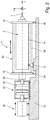
Figur 1 , so dass hinsichtlich des Aufbaus auf diese Beschreibung verwiesen wird. Das Antriebsgestänge 50 hat mehrere sich zwischen den Flanschen 48, 52 erstreckende Übertragungsstreben 56, die in Parallelabstand zur Spindelachse und zum Spindelgehäuse 14 verlaufen. - Anhand der
Figuren 3 bis 7 wird der prinzipielle Aufbau der Spindelanordnung 1 erläutert, wobei der Einfachheit halber der die Ausgleichseinrichtung 30 betreffende Teil nicht dargestellt ist.Figur 3 zeigt dabei die Spindelanordnung 1 im Montagezustand, wobei die eigentliche Spindel von der Abdeckung 42 überdeckt ist. Die Spindelanordnung 1 ist mit der angedeuteten Maschinenstruktur 18 verschraubt. In dieser Darstellung ist noch keine Werkzeugaufnahme 4 an den auskragenden Teil des Rotors 8 angesetzt. Angedeutet inFigur 3 ist auch ein Teil eines Steuerblocks 58, in den die Servoventile zur Ansteuerung des Aktuators 20 und der Ausgleichseinrichtung 30 integriert sind. -
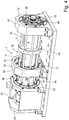
Figur 4 zeigt die Spindelanordnung 1 bei abgenommener Abdeckung 42. Man erkennt in dieser Darstellung die als Standardspindel ausgeführte Spindel 2, die über zwei Lagerböcke 58, 60 an der Maschinenstruktur 18 festgelegt ist. - Die Spindel 2 ist in der anhand
Figur 2 erläuterten Weise mit dem Aktuator 20 und der Ausgleichseinrichtung (nicht dargestellt) verbunden. Letzterer ist in einer Umhausung 62 angeordnet, an der auch der Flansch 52 befestigt ist. - Wie vorstehend erläutert, ist dieser Flansch 52 über das Antriebsgestänge 50 mit den Übertragungsstreben 56 mit dem werkzeugseitigen Stirnflansch 48 verbunden. Andererseits steht der Stirnflansch 52 in Wirkverbindung mit dem hydraulischen Aktuator 20. Gemäß
Figur 4 durchsetzen die die Spindel 2 umgreifenden Antriebsstreben 56 einen Führungsring 64, der das Gehäuse 14 der Spindel 2 umgreift. - Die Spindel ist in den beiden mit der Maschinenstruktur 18 verbundenen Lagerböcken 58, 60 über geeignete Lager, im vorliegenden Fall die beiden Membranlager 10, 46 gelagert, die im Bereich des Stirnflanschs 48 bzw. eines weiteren Spindelflanschs 66 mit der Spindel 2 verbunden sind.
- Die Lagerung des aktuatorseitigen Flansches 52 in der Umhausung 62 erfolgt über das oben beschriebene weitere Membranlager 54, das in der Darstellung gemäß
-
Figur 4 weitestgehend von einem Befestigungsring 68 überdeckt ist. - Über ähnliche Befestigungsringe 70, 72 erfolgt auch die Festlegung der Membranlager 46, 10 in den Lagerböcken 58 bzw. 60. Die Membranlager 10, 46, 54 erlauben - wie erläutert - eine Schwingungsbewegung in z-Richtung und sind jedoch in Radialrichtung äußerst steif ausgebildet, so dass die Bahngenauigkeit der Werkzeugmaschine nicht beeinträchtigt ist.
- Weitere Einzelheiten werden anhand der
Figuren 5 bis 7 erläutert. -
Figur 5 zeigt einen Längsschnitt durch die Spindelanordnung 1 gemäßFigur 4 . Dem gemäß hat die eigentliche Spindel 2 einen im Wesentlichen herkömmlichen Aufbau. Da ein derartiger Spindelaufbau im Prinzip bekannt ist, kann unter Verweis auf die diesbezügliche Fachliteratur auf eine weitere Erläuterung verzichtet werden. - Im Bereich der beiden Lagerböcke 58, 60 ist am Außenumfang des Spindelgehäuses 14 ein Befestigungsflansch 76 beziehungsweise der Stirnflansch 48 vorgesehen, über die jeweils der ringförmige Innenteil der jeweiligen Membranlager 10, 46 festgespannt wird. Das weitere Membranlager 54 ist mit seinem ringförmigen Innenteil mit einer entsprechenden Aufnahme des Flanschs 52 verbunden. Ein außen liegender Ring der Membranlager 54, 10, 46 ist dann über die genannten Befestigungsringe 68, 70, 72 mit der Umhausung 62 des hydraulischen Aktuators 20 bzw. den Lagerböcken 60, 58 verbunden, so dass die Spindel 2 in Radialrichtung exakt geführt ist und eine Schwingung in z-Richtung ermöglicht ist.
- Wie erläutert, ist der Aktuator 20 beim dargestellten Beispiel hydraulisch betätigt. Eine Kolbenstange 80 (siehe auch
Figur 2 ) eines Kolbens des Aktuators ist mit dem Flansch 52 verbunden, so dass die über den Aktuator 20 generierten Schwingungen über das Antriebsgestänge 50 mit den Übertragungsstreben 56 und den Stirnflansch 48 auf das Spindelgehäuse 14 übertragen wird. Wie inFigur 5 gestrichelt angedeutet, steht der Aktuator 20 in Wirkverbindung mit der Ausgleichseinrichtung 30, so dass ein aktiver Impulsausgleich und somit eine Kompensation der über die Schwingung der Spindel 2 eingeleiteten Trägheitskräfte ermöglicht ist. Der hydraulische Aktuator 20 ist beim Beispiel gemäßFigur 5 über eine Konsole 87 in z-Richtung mit der Umhausung 62 verschraubt. -
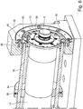
Figur 6 zeigt eine vergrößerte Darstellung des im Bereich des Lagerbocks 58 ausgebildeten Teils der Spindelanordnung 1. In dieser Darstellung gut sichtbar ist die Anbindung des Stirnflansches 48 an den Flansch des Spindelgehäuses 14 und die Klemmung eines Innenrings 82 und des Membranlagers 46. Ein Außenring 86 des in etwa topfförmig ausgebildeten Membranlagers 46 ist über den Befestigungsring 72 am Lagerbock 58 festgelegt, wobei der Befestigungsring 72 in eine entsprechende Rückstufung des Lagerbocks 58 eintaucht. Die Befestigung der anderen Membranlager 10, 54 erfolgt entsprechend. - Gemäß der Darstellung in
Figur 6 umgreift der Führungsring 64 das Spindelgehäuse 14 und ist an den Übertragungsstreben 56 beispielsweise über Klemmschrauben 88 festgelegt, so dass diese untereinander verbunden sind. Eine Verbindung des Führungsrings 64 mit dem Spindelgehäuse 14 erfolgt nicht, so dass die Schwingung direkt in den werkzeugseitigen Teil des Gehäuses 14 eingeleitet wird. - Die
Figuren 7a, 7b zeigen den prinzipiellen Grundaufbau des Schwingungssystems mit der in z-Richtung über den Aktuator (hier nicht gezeigt) zu Schwingungen anregbaren Spindel 2, die über die zwei vorbeschriebenen Membranlager 10, 46 aufgehängt/gelagert ist. Die Schwingungsübertragung erfolgt durch Anregung des aktuatorseitigen Flansches 52, der über das Membranlager 54 gelagert ist. Wie erläutert, werden die Schwingungen dann über das Antriebsgestänge 50 und den Stirnflansch 48 in die Spindel 2 eingeleitet. Bei diesem Beispiel sind die Übertragungsstreben 56 über zwei Führungsringe 64 miteinander verbunden. - Die Schwingungsfrequenz der Spindel 2 liegt im Bereich unter 1000 Hz, wobei die Eigenfrequenz der Anordnung ausgenutzt wird, um die angeregte Schwingung im Bereich der Eigenfrequenz zu unterstützen.
- So sind bei dem in
Figur 7a dargestellten Beispiel die drei Membranlager 10, 54, 46 nicht durchgehend topfförmig ausgebildet sondern mit einer Vielzahl von Ausnehmungen 90 ausgeführt, wobei durch geeignete Geometrie und Größe der Ausnehmungen 90 sowie der Membranstärke die Eigenfrequenz der Membranen einstellbar ist. Das inFigur 7a dargestellte Beispiel hat vergleichsweise großflächige Ausnehmungen 90, so dass die Eigenfrequenz des Aufbaus relativ niedrig, beispielsweise etwa im Bereich von 72 Hz liegt. Bei dem inFigur 7b dargestellten Beispiel sind die Ausnehmungen 90 des Membranlagers 46 gegenüber dem Beispiel gemäßFigur 7a deutlich verkleinert, so dass die Eigenfrequenz des Aufbaus höher, beispielsweise im Bereich von 132 Hz liegt. Bei der Variante gemäßFigur 7b sind die Ausnehmungen der anderen Lagermembranen 10, 54 unverändert. Selbstverständlich kann auch die Geometrie dieser Membranlager zur Anpassung der Eigenfrequenz des Lagersystems variiert werden. Auf diese Weise ist es möglich, durch geeignete Auslegung der Spindelaufhängung und der Amplitude und Frequenz des Aktuators sowie der Schwingmasse der Ausgleichseinrichtung 30 die Schwingung in den Bereich der Eigenfrequenz der Spindelanordnung 1 zu legen, so dass die Energie für die Schwingungserregung minimal ist. - Durch die gegengleich schwingende Ausgleichsmasse 32 oder entsprechende Ausgleichseinrichtungen wird ein Einleiten der Schwingungen in die Maschinenstruktur zuverlässig verhindert, so dass die Bahngenauigkeit gegenüber herkömmlichen Lösungen deutlich erhöht ist. Dennoch sollte ein Augenmerk darauf gerichtet werden, dass bei der Bearbeitung Prozessparameter gewählt werden, die keine Anregung der Maschinenstruktur in deren Eigenfrequenz hervorrufen.
- Die beim Ausführungsbeispiel gemäß
Figur 1 mögliche Einleitung von Schwingungen in allen drei Hauptachseinrichtungen der Werkzeugmaschine erlaubt es, flexibel auf die zu fertigenden Werkzeugstücke zu reagieren. So ist es beispielsweise beim Bohren ausreichend, die Schwingungen lediglich entlang der Z-Achse (Spindellängsachse) einzuleiten. Ergänzend ermöglicht eine Schwingung in der X- und Y-Richtung eine helikale Bohrungsbearbeitung. Beim Fräsen einer Tasche oder dergleichen wird hingegen eine Schwingung in X- und Y-Richtung bevorzugt, so dass eine trochoide Bearbeitung erfolgt. - Bei dem Ausführungsbeispiel gemäß
Figur 1 ist die Schwingung in der X- und Y-Richtung im Wesentlichen in den Bereich des werkzeugseitigen Lagerbocks 58 integriert. Die Verwendung eines Luftlagers 12 in diesem Bereich hat den Vorteil eines geringen Reibbeiwerts und lässt zusätzlich eine Bewegung in axialer Richtung zu. Die Schwingung in Z-Richtung wird durch die Resonanzfrequenz der aktuatorseitigen Lageraufhängung (Membranlager 10) unterstützt. - Die Effekte einer Schwingungsüberlagerung ermöglichen eine effizientere Versorgung der Schneidkanten des Werkzeugs 6 mit Kühlschmierstoff, das Ausspülen von Spänen, wobei der intermittierende Schneideneingriff bei effektiv höheren Spanungsdicken zu einer signifikanten Verbesserung des Zerspanungsvorgangs führt. Insbesondere große Schwingungsamplituden im Bereich von mehr als 0,1 mm sollen ein Spaltmaß zwischen Werkstück und Schneide realisieren, wodurch eine turbulente Strömung des Kühlschmierstoffstroms entsteht. Dieser Effekt verbessert die Kühlschmierung der Schneide und reduziert den Werkzeugverschleiß. Beispielsweise bei der Bearbeitung von Faserverbundmaterialien wird dadurch einer Schädigung der Kunststoffmatrix vorgebeugt.
- Zusätzlich kann eine signifikante Verbesserung im Standzeitverhalten der Werkzeuge festgestellt werden. So dass alles in Allem aufgrund des verbesserten Spanbruchs, des verbesserten Späneabtransports, der höheren Werkzeugstandzeit, der Verkürzung der Fertigungszeiten, der Verkürzung der Durchlaufzeiten und der damit einhergehenden Kostensenkung die Produktivität deutlich gesteigert werden kann.
- Offenbart ist eine Spindelanordnung mit einem Aktuator zur Schwingungsanregung eines von der Spindelanordnung getragenen Werkzeugs. Mittels einer Ausgleichseinrichtung erfolgt ein aktiver Impulsausgleich.
-
- 1
- Spindelanordnung
- 2
- Spindel
- 4
- Werkzeugaufnahme
- 6
- Werkzeug
- 8
- Rotor
- 10
- Membranlager
- 12
- Luftlager
- 14
- Spindelgehäuse
- 16
- Befestigungselement
- 18
- Maschinenstruktur
- 20
- Aktuator
- 22
- Kolben
- 24
- Zylindergehäuse
- 26
- Druckraum
- 28
- Druckraum
- 30
- Ausgleichseinrichtung
- 32
- Ausgleichsmasse
- 34
- Ausgleichskolben
- 36
- Druckraum
- 38
- Druckraum
- 40
- Ausgleichslager
- 42
- Gehäuse
- 44
- weiterer Aktuator
- 46
- Membranlager
- 48
- Stirnflansch
- 50
- Antriebsgestänge
- 52
- Flansch
- 54
- weiteres Membranlager
- 56
- Übertragungsstrebe
- 58
- Lagerbock
- 60
- Lagerbock
- 62
- Umhausung
- 64
- Führungsring
- 66
- Spindelflansch
- 68
- Befestigungsring
- 70
- Befestigungsring
- 72
- Befestigungsring
- 76
- Befestigungsflansch
- 78
- Befestigungsflansch
- 80
- Kolbenstange
- 82
- Innenring
- 84
- Klemmring
- 86
- Außenring
- 87
- Konsole
- 88
- Klemmschraube
- 90
- Ausnehmung
Claims (14)
- Spindelanordnung für eine Werkzeugmaschine mit einer Spindel (2) zum Antreiben eines Werkzeugs (6) und mit einem Aktuator (20) zur Schwingungsanregung des Werkzeugs (6), wobei die Spindelanordnung mit einer Ausgleichseinrichtung (30) zur zumindest teilweisen Kompensation der durch die Schwingungsanregung erzeugten Trägheitskräfte im Spindelbereich ausgeführt ist, wobei der Aktuator (20) eine Ausgleichsmasse (32) antreibt, dadurch gekennzeichnet, dass eine weitere Ausgleichsmasse die Spindel (2) umgreift und über zumindest einen weiteren Aktuator (44) angetrieben ist.
- Spindelanordnung nach Patentanspruch 1, wobei die Ausgleichseinrichtung (30) die Ausgleichsmasse (32) hat, die gegengleich zur auf das Werkzeug (6) übertragenen Schwingung angetrieben ist.
- Spindelanordnung nach Patentanspruch 2, wobei die Schwingmassen der Spindel (2) und der Ausgleichsmasse (32), die Frequenz sowie die Schwingungsamplitude so gewählt sind, dass sich die gegenläufig wirkenden Trägheitskräfte im Wesentlichen aufheben.
- Spindelanordnung nach einem der vorhergehenden Patentansprüche, wobei die Schwingungsfrequenz weniger als 1 kHz, vorzugsweise etwa 200 Hz beträgt.
- Spindelanordnung nach einem der vorhergehenden Patentansprüche, wobei die Schwingungsamplitude im Bereich von 0,05 mm bis 1 mm, vorzugsweise im Bereich von 0,1 mm bis 0,5 mm liegt.
- Spindelanordnung nach einem der vorhergehenden Patentansprüche, wobei die Schwingungsanregung über den Aktuator (20, 44) oder eine Aktuatoranordnung in zwei oder drei Achsen (x, y, z) erfolgt.
- Spindelanordnung nach Anspruch 1, wobei die weitere Ausgleichsmasse über zwei diametral angeordnete Aktuatoren (44) angetrieben ist.
- Spindelanordnung nach einem der vorhergehenden Patentansprüche, wobei die Spindel (2) oder ein Rotor (8) der Spindel (2) über zwei die Schwingung ermöglichende Lager (10, 12; 46) abgestützt ist.
- Spindelanordnung nach Patentanspruch 8, mit einem zusätzlichen Lager (54) im Ankoppelbereich der Spindel (2) bzw. des Rotors (8) an den Aktuator (20).
- Spindelanordnung nach Patentanspruch 8 oder 9, wobei die Lager Luftlager (12) oder Festkörperelemente, insbesondere Membranlager (10, 46, 54) sind.
- Spindelanordnung nach einem der Patentansprüche 8 bis 10, wobei der Aktuator (20, 44) oder die Aktuatoranordnung und/oder die Ausgleichseinrichtung (30) in ein Spindelgehäuse (14) der Spindel (2) integriert sind.
- Spindelanordnung nach einem der Patentansprüche 8 bis 11, mit einem Antriebsgestänge (50) zur Schwingungsübertragung zwischen Aktuator (20) und Spindel (2).
- Spindelanordnung nach einem der vorhergehenden Patentansprüche, wobei die Auslegung der zur Schwingung angeregten Bauelemente und die Wahl der Schwingungsparameter derart erfolgen, dass das Gesamtspindelsystem in einer definierten Eigenfrequenz schwingt.
- Spindelanordnung nach einem der vorhergehenden Patentansprüche, wobei der oder die Aktuatoren (20, 44) hydraulisch, mechanisch oder elektromechanisch angetrieben sind.
Applications Claiming Priority (2)
| Application Number | Priority Date | Filing Date | Title |
|---|---|---|---|
| DE102015101167.0A DE102015101167A1 (de) | 2015-01-27 | 2015-01-27 | Spindelanordnung |
| PCT/EP2016/051579 WO2016120274A1 (de) | 2015-01-27 | 2016-01-26 | Spindelanordnung |
Publications (2)
| Publication Number | Publication Date |
|---|---|
| EP3250340A1 EP3250340A1 (de) | 2017-12-06 |
| EP3250340B1 true EP3250340B1 (de) | 2021-11-03 |
Family
ID=55273235
Family Applications (1)
| Application Number | Title | Priority Date | Filing Date |
|---|---|---|---|
| EP16702372.0A Active EP3250340B1 (de) | 2015-01-27 | 2016-01-26 | Spindelanordnung |
Country Status (5)
| Country | Link |
|---|---|
| US (1) | US11097391B2 (de) |
| EP (1) | EP3250340B1 (de) |
| CN (1) | CN107405738B (de) |
| DE (1) | DE102015101167A1 (de) |
| WO (1) | WO2016120274A1 (de) |
Families Citing this family (8)
| Publication number | Priority date | Publication date | Assignee | Title |
|---|---|---|---|---|
| DE102015101167A1 (de) | 2015-01-27 | 2016-07-28 | Technische Universität Wien | Spindelanordnung |
| EP3530359B1 (de) * | 2018-02-26 | 2023-10-18 | Telsonic Holding AG | Vorrichtung und verfahren zum bearbeiten von werkstücken oder gegenständen |
| CN109991920B (zh) * | 2019-03-13 | 2022-05-27 | 西安万威机械制造股份有限公司 | 适用于韧性金属材料加工的正弦动力钻孔方法及控制系统 |
| CN111638683B (zh) * | 2020-06-09 | 2024-08-16 | 新代科技(苏州)有限公司 | 断屑控制系统及其控制方法 |
| DE102020208876A1 (de) * | 2020-07-16 | 2022-01-20 | Fraunhofer-Gesellschaft zur Förderung der angewandten Forschung eingetragener Verein | Aktor, Werkzeugmaschine und Verfahren zum spanenden Bearbeiten |
| CN112809027B (zh) * | 2021-01-14 | 2022-02-18 | 江苏博尚工业装备有限公司 | 一种机床用低震动同步内藏式电主轴 |
| CN114453959B (zh) * | 2022-03-23 | 2022-12-20 | 日照职业技术学院 | 一种偏心弧面凸轮加工的主轴减振自动控制系统 |
| CN116652676B (zh) * | 2023-05-31 | 2025-07-04 | 哈尔滨理工大学 | 一种用于叠层材料加工的自调整冷却吸屑装置及控制方法 |
Family Cites Families (17)
| Publication number | Priority date | Publication date | Assignee | Title |
|---|---|---|---|---|
| DE3122979A1 (de) * | 1981-06-10 | 1983-01-05 | Hilti AG, 9494 Schaan | Bohr- oder meisselhammer |
| IL105743A0 (en) * | 1992-06-11 | 1993-09-22 | Dov Shilkrut | Penetrating tool system |
| DE19653233A1 (de) * | 1996-12-20 | 1998-07-02 | Schneider Gmbh & Co Kg | Hochgeschwindigkeits-Drehmaschine zum Herstellen optisch wirksamer Oberflächen |
| DE19810996A1 (de) * | 1998-03-13 | 1999-09-16 | Krauss Maffei Ag | Impulsentkoppelter Direktantrieb |
| WO2006022592A1 (en) | 2004-08-26 | 2006-03-02 | Agency For Science, Technology And Research | Apparatus for ultrasonic vibration-assisted machining |
| JP4539499B2 (ja) | 2004-11-09 | 2010-09-08 | 株式会社デンソー | 振動加工装置及び振動加工方法 |
| EP1669148B1 (de) | 2004-12-13 | 2018-01-17 | Fritz Studer AG | Werkzeugeinheit zur ultraschallunterstützten rotativen Bearbeitung |
| JP2007007810A (ja) * | 2005-07-01 | 2007-01-18 | Bosch Corp | 超音波加工スピンドル装置 |
| JP4627705B2 (ja) * | 2005-09-15 | 2011-02-09 | 日本発條株式会社 | 板ばねの荷重測定装置、およびプログラム |
| JPWO2008010414A1 (ja) * | 2006-07-21 | 2009-12-17 | コニカミノルタオプト株式会社 | 切削用振動体、振動切削ユニット、加工装置、成形金型、及び光学素子 |
| DE102007053350B4 (de) * | 2007-10-30 | 2013-10-10 | Chiron-Werke Gmbh & Co Kg | Verfahren zur spanabhebenden Bearbeitung von Werkstücken |
| GB0804967D0 (en) * | 2008-03-18 | 2008-04-16 | Black & Decker Inc | Powered hammer with a vibration dampening mechanism |
| DE102010040636A1 (de) | 2010-09-13 | 2012-03-15 | Behr Gmbh & Co. Kg | Zylinderklappe sowie Luftmischsystem zur Mischung von unterschiedlich temperierten Luftströmen |
| DE102010048636B4 (de) | 2010-10-15 | 2017-11-16 | Sauer Ultrasonic Gmbh | Werkzeugmaschine und Verfahren zur Bearbeitung eines Werkstücks mit einem Werkzeug |
| AT511551B1 (de) | 2011-05-18 | 2013-10-15 | Univ Wien Tech | Vorrichtung und verfahren zur mechanischen bearbeitung eines werkstücks |
| AT513094B1 (de) | 2012-03-28 | 2015-01-15 | Univ Wien Tech | Vorrichtung, insbesondere Spanwerkzeug |
| DE102015101167A1 (de) | 2015-01-27 | 2016-07-28 | Technische Universität Wien | Spindelanordnung |
-
2015
- 2015-01-27 DE DE102015101167.0A patent/DE102015101167A1/de not_active Withdrawn
-
2016
- 2016-01-26 WO PCT/EP2016/051579 patent/WO2016120274A1/de not_active Ceased
- 2016-01-26 US US15/546,781 patent/US11097391B2/en active Active
- 2016-01-26 EP EP16702372.0A patent/EP3250340B1/de active Active
- 2016-01-26 CN CN201680007454.9A patent/CN107405738B/zh not_active Expired - Fee Related
Non-Patent Citations (1)
| Title |
|---|
| None * |
Also Published As
| Publication number | Publication date |
|---|---|
| DE102015101167A1 (de) | 2016-07-28 |
| US20180021903A1 (en) | 2018-01-25 |
| CN107405738B (zh) | 2020-12-22 |
| US11097391B2 (en) | 2021-08-24 |
| WO2016120274A1 (de) | 2016-08-04 |
| CN107405738A (zh) | 2017-11-28 |
| EP3250340A1 (de) | 2017-12-06 |
Similar Documents
| Publication | Publication Date | Title |
|---|---|---|
| EP3250340A1 (de) | Spindelanordnung | |
| EP2655006B1 (de) | Vorrichtung mit zwei schwingungskomponenten zum spanenden bearbeiten eines werkstücks und verfahren dafür | |
| EP3003610B1 (de) | Werkzeug, werkzeugmaschine und werkstückbearbeitungsverfahren | |
| EP0625083B1 (de) | Vorrichtung zum schleifen von werkstücken | |
| DE19810996A1 (de) | Impulsentkoppelter Direktantrieb | |
| DE202016102124U1 (de) | Werkzeugantrieb mit Spindelwelle | |
| DE102007025934B4 (de) | Werkzeugmaschine | |
| EP3468744B1 (de) | Bearbeitungsvorrichtung mit einer schwingungsdämpfungsvorrichtung und verfahren | |
| DE102006049867B4 (de) | Werkzeugmaschine und Verfahren zur Unterdrückung von Ratterschwingungen | |
| WO2007062985A1 (de) | Verfahren zur reduktion von schwingungen eines maschinenelements und/oder eines werkstücks | |
| EP3840914B1 (de) | Verstellvorrichtung für eine werkzeugmaschine mit verringerter schwingungsneigung | |
| EP1742762B1 (de) | Vorrichtung zur erzeugung von mikrostrukturen | |
| WO2022013053A1 (de) | Aktor, werkzeugmaschine und verfahren zum spanenden bearbeiten | |
| DE10229134A1 (de) | Vorrichtung und Verfahren zur Werkstückbearbeitung mit rotierenden Werkzeugen | |
| DE102009039203A1 (de) | Einrichtung zur Kompensation von Drehmomenten, die durch Beschleunigung von redundanten Zusatzachsen bei Mess- und Werkzeugmaschinen entstehen mittels einer Mehrzahl von koordiniert linear bewegbarer Ausgleichsmassen | |
| EP2374574A1 (de) | Hochgeschwindigkeits-Honmaschine | |
| AT513094A1 (de) | Vorrichtung, insbesondere Spanwerkzeug | |
| DE3421973A1 (de) | Werkzeugmaschine | |
| WO2001075412A1 (de) | Auswuchtvorrichtung und -verfahren | |
| EP1741514A1 (de) | Vorrichtung zum Schleifen und/oder Finishen eines Werkstücks | |
| DE102014119141B4 (de) | Oszillierend antreibbare Werkzeugmaschine, Werkzeug, Koppelelement und System | |
| EP2937149B1 (de) | Einrichtung zum bearbeiten von werkstücken mittels hochfrequenter schwingungen | |
| DE102023207042A1 (de) | Werkzeugspannfutter für ein rotierendes Werkzeug | |
| DE3336920C1 (de) | Vorrichtung zur Kompensation von durch Bearbeitungskräfte und/oder Eigengewicht bedingten Verlagerungen eines bewegten, auskragenden Werkzeugmaschinenteils | |
| WO2024218221A1 (de) | Bearbeitungszentrum zur spanenden bearbeitung eines länglichen metallischen werkstücks |
Legal Events
| Date | Code | Title | Description |
|---|---|---|---|
| STAA | Information on the status of an ep patent application or granted ep patent |
Free format text: STATUS: THE INTERNATIONAL PUBLICATION HAS BEEN MADE |
|
| PUAI | Public reference made under article 153(3) epc to a published international application that has entered the european phase |
Free format text: ORIGINAL CODE: 0009012 |
|
| STAA | Information on the status of an ep patent application or granted ep patent |
Free format text: STATUS: REQUEST FOR EXAMINATION WAS MADE |
|
| 17P | Request for examination filed |
Effective date: 20170816 |
|
| AK | Designated contracting states |
Kind code of ref document: A1 Designated state(s): AL AT BE BG CH CY CZ DE DK EE ES FI FR GB GR HR HU IE IS IT LI LT LU LV MC MK MT NL NO PL PT RO RS SE SI SK SM TR |
|
| AX | Request for extension of the european patent |
Extension state: BA ME |
|
| DAV | Request for validation of the european patent (deleted) | ||
| DAX | Request for extension of the european patent (deleted) | ||
| STAA | Information on the status of an ep patent application or granted ep patent |
Free format text: STATUS: EXAMINATION IS IN PROGRESS |
|
| 17Q | First examination report despatched |
Effective date: 20200619 |
|
| GRAP | Despatch of communication of intention to grant a patent |
Free format text: ORIGINAL CODE: EPIDOSNIGR1 |
|
| STAA | Information on the status of an ep patent application or granted ep patent |
Free format text: STATUS: GRANT OF PATENT IS INTENDED |
|
| INTG | Intention to grant announced |
Effective date: 20210527 |
|
| GRAS | Grant fee paid |
Free format text: ORIGINAL CODE: EPIDOSNIGR3 |
|
| GRAA | (expected) grant |
Free format text: ORIGINAL CODE: 0009210 |
|
| STAA | Information on the status of an ep patent application or granted ep patent |
Free format text: STATUS: THE PATENT HAS BEEN GRANTED |
|
| AK | Designated contracting states |
Kind code of ref document: B1 Designated state(s): AL AT BE BG CH CY CZ DE DK EE ES FI FR GB GR HR HU IE IS IT LI LT LU LV MC MK MT NL NO PL PT RO RS SE SI SK SM TR |
|
| RAP3 | Party data changed (applicant data changed or rights of an application transferred) |
Owner name: TECHNISCHE UNIVERSITAET WIEN |
|
| REG | Reference to a national code |
Ref country code: GB Ref legal event code: FG4D Free format text: NOT ENGLISH |
|
| REG | Reference to a national code |
Ref country code: AT Ref legal event code: REF Ref document number: 1443540 Country of ref document: AT Kind code of ref document: T Effective date: 20211115 Ref country code: CH Ref legal event code: EP |
|
| REG | Reference to a national code |
Ref country code: DE Ref legal event code: R096 Ref document number: 502016014083 Country of ref document: DE |
|
| REG | Reference to a national code |
Ref country code: IE Ref legal event code: FG4D Free format text: LANGUAGE OF EP DOCUMENT: GERMAN |
|
| REG | Reference to a national code |
Ref country code: LT Ref legal event code: MG9D |
|
| REG | Reference to a national code |
Ref country code: NL Ref legal event code: MP Effective date: 20211103 |
|
| PG25 | Lapsed in a contracting state [announced via postgrant information from national office to epo] |
Ref country code: RS Free format text: LAPSE BECAUSE OF FAILURE TO SUBMIT A TRANSLATION OF THE DESCRIPTION OR TO PAY THE FEE WITHIN THE PRESCRIBED TIME-LIMIT Effective date: 20211103 Ref country code: LT Free format text: LAPSE BECAUSE OF FAILURE TO SUBMIT A TRANSLATION OF THE DESCRIPTION OR TO PAY THE FEE WITHIN THE PRESCRIBED TIME-LIMIT Effective date: 20211103 Ref country code: FI Free format text: LAPSE BECAUSE OF FAILURE TO SUBMIT A TRANSLATION OF THE DESCRIPTION OR TO PAY THE FEE WITHIN THE PRESCRIBED TIME-LIMIT Effective date: 20211103 Ref country code: BG Free format text: LAPSE BECAUSE OF FAILURE TO SUBMIT A TRANSLATION OF THE DESCRIPTION OR TO PAY THE FEE WITHIN THE PRESCRIBED TIME-LIMIT Effective date: 20220203 |
|
| PGFP | Annual fee paid to national office [announced via postgrant information from national office to epo] |
Ref country code: GB Payment date: 20220125 Year of fee payment: 7 Ref country code: CH Payment date: 20220125 Year of fee payment: 7 |
|
| PG25 | Lapsed in a contracting state [announced via postgrant information from national office to epo] |
Ref country code: IS Free format text: LAPSE BECAUSE OF FAILURE TO SUBMIT A TRANSLATION OF THE DESCRIPTION OR TO PAY THE FEE WITHIN THE PRESCRIBED TIME-LIMIT Effective date: 20220303 Ref country code: SE Free format text: LAPSE BECAUSE OF FAILURE TO SUBMIT A TRANSLATION OF THE DESCRIPTION OR TO PAY THE FEE WITHIN THE PRESCRIBED TIME-LIMIT Effective date: 20211103 Ref country code: PT Free format text: LAPSE BECAUSE OF FAILURE TO SUBMIT A TRANSLATION OF THE DESCRIPTION OR TO PAY THE FEE WITHIN THE PRESCRIBED TIME-LIMIT Effective date: 20220303 Ref country code: PL Free format text: LAPSE BECAUSE OF FAILURE TO SUBMIT A TRANSLATION OF THE DESCRIPTION OR TO PAY THE FEE WITHIN THE PRESCRIBED TIME-LIMIT Effective date: 20211103 Ref country code: NO Free format text: LAPSE BECAUSE OF FAILURE TO SUBMIT A TRANSLATION OF THE DESCRIPTION OR TO PAY THE FEE WITHIN THE PRESCRIBED TIME-LIMIT Effective date: 20220203 Ref country code: NL Free format text: LAPSE BECAUSE OF FAILURE TO SUBMIT A TRANSLATION OF THE DESCRIPTION OR TO PAY THE FEE WITHIN THE PRESCRIBED TIME-LIMIT Effective date: 20211103 Ref country code: LV Free format text: LAPSE BECAUSE OF FAILURE TO SUBMIT A TRANSLATION OF THE DESCRIPTION OR TO PAY THE FEE WITHIN THE PRESCRIBED TIME-LIMIT Effective date: 20211103 Ref country code: HR Free format text: LAPSE BECAUSE OF FAILURE TO SUBMIT A TRANSLATION OF THE DESCRIPTION OR TO PAY THE FEE WITHIN THE PRESCRIBED TIME-LIMIT Effective date: 20211103 Ref country code: GR Free format text: LAPSE BECAUSE OF FAILURE TO SUBMIT A TRANSLATION OF THE DESCRIPTION OR TO PAY THE FEE WITHIN THE PRESCRIBED TIME-LIMIT Effective date: 20220204 Ref country code: ES Free format text: LAPSE BECAUSE OF FAILURE TO SUBMIT A TRANSLATION OF THE DESCRIPTION OR TO PAY THE FEE WITHIN THE PRESCRIBED TIME-LIMIT Effective date: 20211103 |
|
| PGFP | Annual fee paid to national office [announced via postgrant information from national office to epo] |
Ref country code: FR Payment date: 20220120 Year of fee payment: 7 |
|
| PG25 | Lapsed in a contracting state [announced via postgrant information from national office to epo] |
Ref country code: SM Free format text: LAPSE BECAUSE OF FAILURE TO SUBMIT A TRANSLATION OF THE DESCRIPTION OR TO PAY THE FEE WITHIN THE PRESCRIBED TIME-LIMIT Effective date: 20211103 Ref country code: SK Free format text: LAPSE BECAUSE OF FAILURE TO SUBMIT A TRANSLATION OF THE DESCRIPTION OR TO PAY THE FEE WITHIN THE PRESCRIBED TIME-LIMIT Effective date: 20211103 Ref country code: RO Free format text: LAPSE BECAUSE OF FAILURE TO SUBMIT A TRANSLATION OF THE DESCRIPTION OR TO PAY THE FEE WITHIN THE PRESCRIBED TIME-LIMIT Effective date: 20211103 Ref country code: EE Free format text: LAPSE BECAUSE OF FAILURE TO SUBMIT A TRANSLATION OF THE DESCRIPTION OR TO PAY THE FEE WITHIN THE PRESCRIBED TIME-LIMIT Effective date: 20211103 Ref country code: DK Free format text: LAPSE BECAUSE OF FAILURE TO SUBMIT A TRANSLATION OF THE DESCRIPTION OR TO PAY THE FEE WITHIN THE PRESCRIBED TIME-LIMIT Effective date: 20211103 Ref country code: CZ Free format text: LAPSE BECAUSE OF FAILURE TO SUBMIT A TRANSLATION OF THE DESCRIPTION OR TO PAY THE FEE WITHIN THE PRESCRIBED TIME-LIMIT Effective date: 20211103 |
|
| REG | Reference to a national code |
Ref country code: DE Ref legal event code: R097 Ref document number: 502016014083 Country of ref document: DE |
|
| PG25 | Lapsed in a contracting state [announced via postgrant information from national office to epo] |
Ref country code: MC Free format text: LAPSE BECAUSE OF FAILURE TO SUBMIT A TRANSLATION OF THE DESCRIPTION OR TO PAY THE FEE WITHIN THE PRESCRIBED TIME-LIMIT Effective date: 20211103 |
|
| PLBE | No opposition filed within time limit |
Free format text: ORIGINAL CODE: 0009261 |
|
| STAA | Information on the status of an ep patent application or granted ep patent |
Free format text: STATUS: NO OPPOSITION FILED WITHIN TIME LIMIT |
|
| REG | Reference to a national code |
Ref country code: BE Ref legal event code: MM Effective date: 20220131 |
|
| 26N | No opposition filed |
Effective date: 20220804 |
|
| PG25 | Lapsed in a contracting state [announced via postgrant information from national office to epo] |
Ref country code: LU Free format text: LAPSE BECAUSE OF NON-PAYMENT OF DUE FEES Effective date: 20220126 Ref country code: AL Free format text: LAPSE BECAUSE OF FAILURE TO SUBMIT A TRANSLATION OF THE DESCRIPTION OR TO PAY THE FEE WITHIN THE PRESCRIBED TIME-LIMIT Effective date: 20211103 |
|
| PG25 | Lapsed in a contracting state [announced via postgrant information from national office to epo] |
Ref country code: SI Free format text: LAPSE BECAUSE OF FAILURE TO SUBMIT A TRANSLATION OF THE DESCRIPTION OR TO PAY THE FEE WITHIN THE PRESCRIBED TIME-LIMIT Effective date: 20211103 Ref country code: BE Free format text: LAPSE BECAUSE OF NON-PAYMENT OF DUE FEES Effective date: 20220131 |
|
| PG25 | Lapsed in a contracting state [announced via postgrant information from national office to epo] |
Ref country code: IE Free format text: LAPSE BECAUSE OF NON-PAYMENT OF DUE FEES Effective date: 20220126 |
|
| PG25 | Lapsed in a contracting state [announced via postgrant information from national office to epo] |
Ref country code: IT Free format text: LAPSE BECAUSE OF FAILURE TO SUBMIT A TRANSLATION OF THE DESCRIPTION OR TO PAY THE FEE WITHIN THE PRESCRIBED TIME-LIMIT Effective date: 20211103 |
|
| P01 | Opt-out of the competence of the unified patent court (upc) registered |
Effective date: 20230630 |
|
| REG | Reference to a national code |
Ref country code: CH Ref legal event code: PL |
|
| GBPC | Gb: european patent ceased through non-payment of renewal fee |
Effective date: 20230126 |
|
| PG25 | Lapsed in a contracting state [announced via postgrant information from national office to epo] |
Ref country code: LI Free format text: LAPSE BECAUSE OF NON-PAYMENT OF DUE FEES Effective date: 20230131 Ref country code: GB Free format text: LAPSE BECAUSE OF NON-PAYMENT OF DUE FEES Effective date: 20230126 Ref country code: CH Free format text: LAPSE BECAUSE OF NON-PAYMENT OF DUE FEES Effective date: 20230131 |
|
| PG25 | Lapsed in a contracting state [announced via postgrant information from national office to epo] |
Ref country code: FR Free format text: LAPSE BECAUSE OF NON-PAYMENT OF DUE FEES Effective date: 20230131 |
|
| PG25 | Lapsed in a contracting state [announced via postgrant information from national office to epo] |
Ref country code: HU Free format text: LAPSE BECAUSE OF FAILURE TO SUBMIT A TRANSLATION OF THE DESCRIPTION OR TO PAY THE FEE WITHIN THE PRESCRIBED TIME-LIMIT; INVALID AB INITIO Effective date: 20160126 |
|
| PG25 | Lapsed in a contracting state [announced via postgrant information from national office to epo] |
Ref country code: MK Free format text: LAPSE BECAUSE OF FAILURE TO SUBMIT A TRANSLATION OF THE DESCRIPTION OR TO PAY THE FEE WITHIN THE PRESCRIBED TIME-LIMIT Effective date: 20211103 Ref country code: CY Free format text: LAPSE BECAUSE OF FAILURE TO SUBMIT A TRANSLATION OF THE DESCRIPTION OR TO PAY THE FEE WITHIN THE PRESCRIBED TIME-LIMIT Effective date: 20211103 |
|
| PG25 | Lapsed in a contracting state [announced via postgrant information from national office to epo] |
Ref country code: TR Free format text: LAPSE BECAUSE OF FAILURE TO SUBMIT A TRANSLATION OF THE DESCRIPTION OR TO PAY THE FEE WITHIN THE PRESCRIBED TIME-LIMIT Effective date: 20211103 |
|
| PG25 | Lapsed in a contracting state [announced via postgrant information from national office to epo] |
Ref country code: MT Free format text: LAPSE BECAUSE OF FAILURE TO SUBMIT A TRANSLATION OF THE DESCRIPTION OR TO PAY THE FEE WITHIN THE PRESCRIBED TIME-LIMIT Effective date: 20211103 |
|
| PGFP | Annual fee paid to national office [announced via postgrant information from national office to epo] |
Ref country code: DE Payment date: 20260128 Year of fee payment: 11 |
|
| PGFP | Annual fee paid to national office [announced via postgrant information from national office to epo] |
Ref country code: AT Payment date: 20260129 Year of fee payment: 11 |