EP3250423B1 - Procédé permettant de faire fonctionner un système de freinage et système de freinage dans lequel le procédé est mis en oeuvre - Google Patents
Procédé permettant de faire fonctionner un système de freinage et système de freinage dans lequel le procédé est mis en oeuvre Download PDFInfo
- Publication number
- EP3250423B1 EP3250423B1 EP16700896.0A EP16700896A EP3250423B1 EP 3250423 B1 EP3250423 B1 EP 3250423B1 EP 16700896 A EP16700896 A EP 16700896A EP 3250423 B1 EP3250423 B1 EP 3250423B1
- Authority
- EP
- European Patent Office
- Prior art keywords
- pressure
- supply device
- pressure supply
- wheel brakes
- piston
- Prior art date
- Legal status (The legal status is an assumption and is not a legal conclusion. Google has not performed a legal analysis and makes no representation as to the accuracy of the status listed.)
- Active
Links
Images
Classifications
-
- B—PERFORMING OPERATIONS; TRANSPORTING
- B60—VEHICLES IN GENERAL
- B60T—VEHICLE BRAKE CONTROL SYSTEMS OR PARTS THEREOF; BRAKE CONTROL SYSTEMS OR PARTS THEREOF, IN GENERAL; ARRANGEMENT OF BRAKING ELEMENTS ON VEHICLES IN GENERAL; PORTABLE DEVICES FOR PREVENTING UNWANTED MOVEMENT OF VEHICLES; VEHICLE MODIFICATIONS TO FACILITATE COOLING OF BRAKES
- B60T8/00—Arrangements for adjusting wheel-braking force to meet varying vehicular or ground-surface conditions, e.g. limiting or varying distribution of braking force
- B60T8/32—Arrangements for adjusting wheel-braking force to meet varying vehicular or ground-surface conditions, e.g. limiting or varying distribution of braking force responsive to a speed condition, e.g. acceleration or deceleration
- B60T8/34—Arrangements for adjusting wheel-braking force to meet varying vehicular or ground-surface conditions, e.g. limiting or varying distribution of braking force responsive to a speed condition, e.g. acceleration or deceleration having a fluid pressure regulator responsive to a speed condition
- B60T8/40—Arrangements for adjusting wheel-braking force to meet varying vehicular or ground-surface conditions, e.g. limiting or varying distribution of braking force responsive to a speed condition, e.g. acceleration or deceleration having a fluid pressure regulator responsive to a speed condition comprising an additional fluid circuit including fluid pressurising means for modifying the pressure of the braking fluid, e.g. including wheel driven pumps for detecting a speed condition, or pumps which are controlled by means independent of the braking system
- B60T8/404—Control of the pump unit
- B60T8/4054—Control of the pump unit involving the delivery pressure control
-
- B—PERFORMING OPERATIONS; TRANSPORTING
- B60—VEHICLES IN GENERAL
- B60T—VEHICLE BRAKE CONTROL SYSTEMS OR PARTS THEREOF; BRAKE CONTROL SYSTEMS OR PARTS THEREOF, IN GENERAL; ARRANGEMENT OF BRAKING ELEMENTS ON VEHICLES IN GENERAL; PORTABLE DEVICES FOR PREVENTING UNWANTED MOVEMENT OF VEHICLES; VEHICLE MODIFICATIONS TO FACILITATE COOLING OF BRAKES
- B60T13/00—Transmitting braking action from initiating means to ultimate brake actuator with power assistance or drive; Brake systems incorporating such transmitting means, e.g. air-pressure brake systems
- B60T13/74—Transmitting braking action from initiating means to ultimate brake actuator with power assistance or drive; Brake systems incorporating such transmitting means, e.g. air-pressure brake systems with electrical assistance or drive
- B60T13/745—Transmitting braking action from initiating means to ultimate brake actuator with power assistance or drive; Brake systems incorporating such transmitting means, e.g. air-pressure brake systems with electrical assistance or drive acting on a hydraulic system, e.g. a master cylinder
-
- B—PERFORMING OPERATIONS; TRANSPORTING
- B60—VEHICLES IN GENERAL
- B60T—VEHICLE BRAKE CONTROL SYSTEMS OR PARTS THEREOF; BRAKE CONTROL SYSTEMS OR PARTS THEREOF, IN GENERAL; ARRANGEMENT OF BRAKING ELEMENTS ON VEHICLES IN GENERAL; PORTABLE DEVICES FOR PREVENTING UNWANTED MOVEMENT OF VEHICLES; VEHICLE MODIFICATIONS TO FACILITATE COOLING OF BRAKES
- B60T8/00—Arrangements for adjusting wheel-braking force to meet varying vehicular or ground-surface conditions, e.g. limiting or varying distribution of braking force
- B60T8/32—Arrangements for adjusting wheel-braking force to meet varying vehicular or ground-surface conditions, e.g. limiting or varying distribution of braking force responsive to a speed condition, e.g. acceleration or deceleration
- B60T8/321—Arrangements for adjusting wheel-braking force to meet varying vehicular or ground-surface conditions, e.g. limiting or varying distribution of braking force responsive to a speed condition, e.g. acceleration or deceleration deceleration
- B60T8/3255—Systems in which the braking action is dependent on brake pedal data
- B60T8/3275—Systems with a braking assistant function, i.e. automatic full braking initiation in dependence of brake pedal velocity
-
- B—PERFORMING OPERATIONS; TRANSPORTING
- B60—VEHICLES IN GENERAL
- B60T—VEHICLE BRAKE CONTROL SYSTEMS OR PARTS THEREOF; BRAKE CONTROL SYSTEMS OR PARTS THEREOF, IN GENERAL; ARRANGEMENT OF BRAKING ELEMENTS ON VEHICLES IN GENERAL; PORTABLE DEVICES FOR PREVENTING UNWANTED MOVEMENT OF VEHICLES; VEHICLE MODIFICATIONS TO FACILITATE COOLING OF BRAKES
- B60T13/00—Transmitting braking action from initiating means to ultimate brake actuator with power assistance or drive; Brake systems incorporating such transmitting means, e.g. air-pressure brake systems
- B60T13/10—Transmitting braking action from initiating means to ultimate brake actuator with power assistance or drive; Brake systems incorporating such transmitting means, e.g. air-pressure brake systems with fluid assistance, drive, or release
- B60T13/66—Electrical control in fluid-pressure brake systems
- B60T13/68—Electrical control in fluid-pressure brake systems by electrically-controlled valves
- B60T13/686—Electrical control in fluid-pressure brake systems by electrically-controlled valves in hydraulic systems or parts thereof
-
- B—PERFORMING OPERATIONS; TRANSPORTING
- B60—VEHICLES IN GENERAL
- B60T—VEHICLE BRAKE CONTROL SYSTEMS OR PARTS THEREOF; BRAKE CONTROL SYSTEMS OR PARTS THEREOF, IN GENERAL; ARRANGEMENT OF BRAKING ELEMENTS ON VEHICLES IN GENERAL; PORTABLE DEVICES FOR PREVENTING UNWANTED MOVEMENT OF VEHICLES; VEHICLE MODIFICATIONS TO FACILITATE COOLING OF BRAKES
- B60T13/00—Transmitting braking action from initiating means to ultimate brake actuator with power assistance or drive; Brake systems incorporating such transmitting means, e.g. air-pressure brake systems
- B60T13/74—Transmitting braking action from initiating means to ultimate brake actuator with power assistance or drive; Brake systems incorporating such transmitting means, e.g. air-pressure brake systems with electrical assistance or drive
- B60T13/741—Transmitting braking action from initiating means to ultimate brake actuator with power assistance or drive; Brake systems incorporating such transmitting means, e.g. air-pressure brake systems with electrical assistance or drive acting on an ultimate actuator
-
- B—PERFORMING OPERATIONS; TRANSPORTING
- B60—VEHICLES IN GENERAL
- B60T—VEHICLE BRAKE CONTROL SYSTEMS OR PARTS THEREOF; BRAKE CONTROL SYSTEMS OR PARTS THEREOF, IN GENERAL; ARRANGEMENT OF BRAKING ELEMENTS ON VEHICLES IN GENERAL; PORTABLE DEVICES FOR PREVENTING UNWANTED MOVEMENT OF VEHICLES; VEHICLE MODIFICATIONS TO FACILITATE COOLING OF BRAKES
- B60T8/00—Arrangements for adjusting wheel-braking force to meet varying vehicular or ground-surface conditions, e.g. limiting or varying distribution of braking force
- B60T8/17—Using electrical or electronic regulation means to control braking
- B60T8/172—Determining control parameters used in the regulation, e.g. by calculations involving measured or detected parameters
-
- B—PERFORMING OPERATIONS; TRANSPORTING
- B60—VEHICLES IN GENERAL
- B60T—VEHICLE BRAKE CONTROL SYSTEMS OR PARTS THEREOF; BRAKE CONTROL SYSTEMS OR PARTS THEREOF, IN GENERAL; ARRANGEMENT OF BRAKING ELEMENTS ON VEHICLES IN GENERAL; PORTABLE DEVICES FOR PREVENTING UNWANTED MOVEMENT OF VEHICLES; VEHICLE MODIFICATIONS TO FACILITATE COOLING OF BRAKES
- B60T8/00—Arrangements for adjusting wheel-braking force to meet varying vehicular or ground-surface conditions, e.g. limiting or varying distribution of braking force
- B60T8/17—Using electrical or electronic regulation means to control braking
- B60T8/176—Brake regulation specially adapted to prevent excessive wheel slip during vehicle deceleration, e.g. ABS
- B60T8/1761—Brake regulation specially adapted to prevent excessive wheel slip during vehicle deceleration, e.g. ABS responsive to wheel or brake dynamics, e.g. wheel slip, wheel acceleration or rate of change of brake fluid pressure
-
- B—PERFORMING OPERATIONS; TRANSPORTING
- B60—VEHICLES IN GENERAL
- B60T—VEHICLE BRAKE CONTROL SYSTEMS OR PARTS THEREOF; BRAKE CONTROL SYSTEMS OR PARTS THEREOF, IN GENERAL; ARRANGEMENT OF BRAKING ELEMENTS ON VEHICLES IN GENERAL; PORTABLE DEVICES FOR PREVENTING UNWANTED MOVEMENT OF VEHICLES; VEHICLE MODIFICATIONS TO FACILITATE COOLING OF BRAKES
- B60T8/00—Arrangements for adjusting wheel-braking force to meet varying vehicular or ground-surface conditions, e.g. limiting or varying distribution of braking force
- B60T8/32—Arrangements for adjusting wheel-braking force to meet varying vehicular or ground-surface conditions, e.g. limiting or varying distribution of braking force responsive to a speed condition, e.g. acceleration or deceleration
- B60T8/34—Arrangements for adjusting wheel-braking force to meet varying vehicular or ground-surface conditions, e.g. limiting or varying distribution of braking force responsive to a speed condition, e.g. acceleration or deceleration having a fluid pressure regulator responsive to a speed condition
- B60T8/40—Arrangements for adjusting wheel-braking force to meet varying vehicular or ground-surface conditions, e.g. limiting or varying distribution of braking force responsive to a speed condition, e.g. acceleration or deceleration having a fluid pressure regulator responsive to a speed condition comprising an additional fluid circuit including fluid pressurising means for modifying the pressure of the braking fluid, e.g. including wheel driven pumps for detecting a speed condition, or pumps which are controlled by means independent of the braking system
- B60T8/4072—Systems in which a driver input signal is used as a control signal for the additional fluid circuit which is normally used for braking
- B60T8/4077—Systems in which the booster is used as an auxiliary pressure source
-
- B—PERFORMING OPERATIONS; TRANSPORTING
- B60—VEHICLES IN GENERAL
- B60T—VEHICLE BRAKE CONTROL SYSTEMS OR PARTS THEREOF; BRAKE CONTROL SYSTEMS OR PARTS THEREOF, IN GENERAL; ARRANGEMENT OF BRAKING ELEMENTS ON VEHICLES IN GENERAL; PORTABLE DEVICES FOR PREVENTING UNWANTED MOVEMENT OF VEHICLES; VEHICLE MODIFICATIONS TO FACILITATE COOLING OF BRAKES
- B60T8/00—Arrangements for adjusting wheel-braking force to meet varying vehicular or ground-surface conditions, e.g. limiting or varying distribution of braking force
- B60T8/32—Arrangements for adjusting wheel-braking force to meet varying vehicular or ground-surface conditions, e.g. limiting or varying distribution of braking force responsive to a speed condition, e.g. acceleration or deceleration
- B60T8/34—Arrangements for adjusting wheel-braking force to meet varying vehicular or ground-surface conditions, e.g. limiting or varying distribution of braking force responsive to a speed condition, e.g. acceleration or deceleration having a fluid pressure regulator responsive to a speed condition
- B60T8/40—Arrangements for adjusting wheel-braking force to meet varying vehicular or ground-surface conditions, e.g. limiting or varying distribution of braking force responsive to a speed condition, e.g. acceleration or deceleration having a fluid pressure regulator responsive to a speed condition comprising an additional fluid circuit including fluid pressurising means for modifying the pressure of the braking fluid, e.g. including wheel driven pumps for detecting a speed condition, or pumps which are controlled by means independent of the braking system
- B60T8/4072—Systems in which a driver input signal is used as a control signal for the additional fluid circuit which is normally used for braking
- B60T8/4081—Systems with stroke simulating devices for driver input
-
- B—PERFORMING OPERATIONS; TRANSPORTING
- B60—VEHICLES IN GENERAL
- B60Y—INDEXING SCHEME RELATING TO ASPECTS CROSS-CUTTING VEHICLE TECHNOLOGY
- B60Y2400/00—Special features of vehicle units
- B60Y2400/81—Braking systems
Definitions
- the invention relates to a method for operating a brake system according to the preamble of claim 1 and a brake system according to the preamble of claim 10.
- a "brake-by-wire" brake system for motor vehicles which is a brake pedal operable tandem master cylinder, a hydraulically connected to the master cylinder simulation device, an electrically controllable pressure supply device, which is formed by a cylinder-piston assembly with a hydraulic pressure chamber, whose piston is displaceable by an electromechanical actuator, and a pressure modulation unit for adjusting wheel-individual brake pressures, which per wheel brake has an inlet valve and an outlet valve.
- the wheel brakes are acted upon open Zuschalt- and intake valves by an electrically controlled advancement of the piston of the pressure supply device with the system pressure of the pressure supply device. If the driver makes a panic braking, which leads to an entry into an anti-skid control for all wheel brakes, the initial brake pressure build-up on each of the wheel brakes must be terminated as soon as possible when entering the anti-skid control. For this purpose, the intake valves of all wheel brakes are closed and the advancement of the piston of the pressure supply device is terminated.
- an intake and an exhaust valve per wheel brake and an electrically controllable pressure supply device which comprises a cylinder-piston assembly with a hydraulic pressure chamber, the piston is displaceable by an electromechanical actuator. It is in the DE 10 2011 077 329 A1 described that during an anti-skid control always at least one wheel brake in the sense of a complete pressure equalization between the wheel and pressure chamber via the associated, open inlet valve to the hydraulic pressure chamber of the pressure supply device is connected, so that the brake pressure curve at this wheel exclusively by driving back and forth of the piston Pressure supply device is varied. However, this is not possible in every braking situation.
- the invention is based on the idea in a brake system in which, in a normal control mode in the presence of a predetermined braking condition, a displacement of the piston of the pressure supply device is terminated by outputting a drive signal to the pressure supply device and the intake valves of the wheel brakes, i. all connected to the pressure-supplying device wheel brakes, are closed, to switch to a special control mode when a predetermined condition for the pressure-providing device is present.
- a displacement of the piston of the pressure supply device is terminated by outputting a drive signal to the pressure supply device and the associated intake valve is kept open for at least one selected wheel brake and the associated exhaust valve is at least temporarily opened while the intake valves of the remaining wheel brakes getting closed.
- the invention has the advantage that the brake system is protected from damage, since in the presence of the predetermined braking condition may possibly due to the inertia of the electromechanical actuator from the pressure chamber of the pressure supply device after issuing the drive signal displaced pressure medium volume via the at least temporarily open outlet valve can flow into the pressure medium reservoir ,
- a displacement of the piston in a pressure buildup direction leads to a displacement of pressure medium from the pressure chamber.
- terminating the movement of the pressure-providing device piston is to terminate the movement in the pressure-building direction.
- a brake system that can be controlled in a "brake-by-wire” mode both by the driver and independently of the driver, is normally operated in the "brake-by-wire” mode and operated in a fallback mode can be.
- the predetermined braking condition is preferably the condition that a pressure build-up on each of the wheel brakes connected to the pressure supply device should be stopped or stopped. This condition or requirement is requested, for example, by an anti-lock control function or another control function of the brake system.
- the predefined condition for the pressure-providing device is preferably the condition that the pressure-providing device is in a critical operating state.
- a critical operating state is particularly preferred when the electromechanical actuator is operated with high dynamics.
- a critical operating state is preferably detected on the basis of a speed of the pressure supply device.
- a critical operating state is, for example, when the speed of the pressure-providing device exceeds a predetermined speed threshold. Particularly preferably, a speed of the piston of the pressure-providing device or a rotational speed of the electromechanical actuator for detecting the critical operating state is evaluated.
- the brake system comprises a displacement sensor, which detects the displacement or the position of the piston of the cylinder-piston assembly. Based on the position change of the piston, the piston speed can be determined.
- the electromechanical actuator comprises an electric motor and a rotation-translation gear, wherein a rotor position sensor is provided for detecting a rotor position of the electric motor. Based on the rotor position change, the rotational speed of the electric motor can be determined, which represents the piston speed.
- the critical operating state of the pressure-providing device is additionally recognized on the basis of a position of the pressure-providing device.
- the position / position of the piston of the pressure supply device is used for this purpose.
- a single wheel brake selected wheel brake For reasons of driving stability and to guarantee the fastest possible outflow of the displaced pressure medium volume, preferably more than a single wheel brake selected wheel brake.
- the wheel brakes of an axle of the motor vehicle selected wheel brakes, ie their intake valves are not closed and their exhaust valves are opened at least temporarily.
- the wheel brakes of the rear axle of the motor vehicle are particularly preferably selected wheel brakes.
- a pressure medium volume estimation is preferably carried out, in which it is determined how much pressure medium volume will be displaced from the pressure supply device after the output of the drive signal until the piston of the Pressure supply device comes to a standstill or the predetermined condition for the pressure supply device is no longer present, ie the piston of the pressure supply device comes under the critical operating condition.
- At least one opening time for the outlet valve of the selected wheel brake or for the outlet valves of the selected wheel brakes is preferably determined on the basis of the estimated pressure medium volume.
- the method is switched from the special control mode in the normal control mode when the predetermined condition for the pressure-providing device is no longer present.
- the invention also relates to a brake system for motor vehicles, in which a method according to the invention is carried out.
- the brake system additionally comprises a master cylinder with a housing and two pistons defining two pressure chambers in the housing, wherein each pressure chamber is connected via an electrically operable, advantageously normally open, separating valve separable with wheel brakes.
- the brake system comprises a brake pedal coupled to the master brake cylinder for actuating the master brake cylinder, wherein an actuation of the brake pedal is monitored.
- the brake system comprises a simulation device hydraulically connected to the master brake cylinder, the effect of which can be switched on and off by means of an electrically actuated, advantageously normally closed, simulator valve.
- At least one electrically operable, advantageously normally closed, Zuschaltventil is arranged between the pressure supply device and the inlet valves.
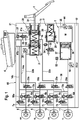
- Fig. 1 an embodiment of a brake system for performing a method according to the invention is shown schematically.
- the brake system essentially comprises an actuatable by means of an actuating or brake pedal 1 master cylinder 2, cooperating with the master cylinder 2 simulation device 3, a master cylinder 2 associated, under atmospheric pressure pressure medium reservoir 4, an electrically controllable pressure supply device 5, which by a cylinder Piston arrangement is formed with a hydraulic pressure chamber 37, the piston 36 is displaceable by an electromechanical actuator, an electrically controllable pressure modulation device for setting wheel-individual brake pressures and an electronic control unit 12th
- the unspecified pressure modulation device comprises according to the example per hydraulically actuated wheel brake 8, 9, 10, 11 of a motor vehicle, not shown, an inlet valve 6a-6d and an exhaust valve 7a-7d, which are hydraulically interconnected in pairs via center ports and to the wheel brakes 8, 9, 10, 11 are connected.
- the inlet ports of the inlet valves 6a-6d are supplied with pressure via brake circuit supply lines 13a, 13b, which are derived in a "brake-by-wire" mode from a system pressure in a system pressure line 38 connected to a pressure chamber 37 of the electrically controllable pressure supply device 5 is present.
- the intake valves 6a-6d is in each case one to the brake circuit supply lines 13a, 13b towards check valve 50a-50d connected in parallel.
- the brake circuit supply lines 13a, 13b are acted upon by hydraulic lines 22a, 22b with the pressures of the pressure chambers 17, 18 of the master cylinder 2.
- the output ports of the exhaust valves 7a-7d are connected in pairs via return lines 14a, 14b to the pressure medium reservoir 4.
- the wheel brakes 10 and 11 are associated with the right front wheel (FR) and the left front wheel (FL) and are connected to the brake circuit supply line 13a (first brake circuit).
- the wheel brakes 8 and 9 are associated with the right rear wheel (RR) and the left rear wheel (RL) and connected to the brake circuit supply line 13b (second brake circuit).
- Other brake circuit partitions are conceivable.
- the master cylinder 2 has in a housing 21 two pistons 15, 16 arranged one behind the other, which delimit hydraulic pressure chambers 17, 18.
- the pressure chambers 17, 18 are on the one hand in the piston 15, 16 formed radial bores and corresponding pressure equalization lines 41a, 41b with the pressure fluid reservoir 4 in connection, the compounds by a relative movement of the piston 17, 18 in the housing 21 are shut off.
- the pressure chambers 17, 18 communicate with the already mentioned brake circuit supply lines 13a, 13b by means of the hydraulic lines 22a, 22b.
- the pressure equalization line 41a is a parallel circuit of a normally open (SO) diagnosis valve 28 with a pressure fluid reservoir 4 toward closing check valve 27 is included.
- SO normally open
- the pressure chambers 17, 18 take unspecified return springs, which position the pistons 15, 16 when the master cylinder 2 is not actuated in a starting position.
- a piston rod 24 couples the pivoting movement of the brake pedal 1 as a result of a pedal operation with the translational movement of the first (master cylinder) piston 15 whose actuation travel is detected by a, preferably redundant, displacement sensor 25.
- the corresponding piston travel signal is a measure of the brake pedal actuation angle. It represents a braking request of the driver.
- an isolation valve 23a, 23b is arranged, which is designed as an electrically actuated, preferably normally open (SO), 2/2-way valve.
- SO normally open
- a pressure sensor 20 connected to the line section 22b detects the pressure built up in the pressure chamber 18 by displacing the second piston 16.
- the simulation device 3 is hydraulically coupled to the master cylinder 2 and consists for example substantially of a simulator 29, a Simulatorfederhunt 30 and a two chambers 29, 30 separating simulator piston 31.
- the simulator piston 31 is supported by an arranged in the Simulatorfederhunt 30 elastic element (For example, a spring), which is advantageously biased on the housing 21 from.
- the simulator chamber 29 is connected by means of an electrically operated simulator valve 32 with the first pressure chamber 17 of the master cylinder 2. Upon specification of a pedal force and open simulator valve 32 pressure fluid flows from the master cylinder pressure chamber 17 in the simulator chamber 29.
- the non-return valve 34 allows largely unhindered backflow of the pressure medium from the simulator chamber 29 to the master cylinder pressure chamber 17.
- Other designs and connections of the simulation device to the master cylinder 2 are conceivable.
- the electrically controllable pressure supply device 5 is designed as a hydraulic cylinder-piston arrangement or a single-circuit electrohydraulic actuator, whose / which piston 36, which limits the pressure chamber 37, actuated by a schematically indicated electric motor 35 with the interposition of a rotationally-translational transmission also shown schematically is.
- a schematically indicated electric motor 35 with the interposition of a rotationally-translational transmission also shown schematically is.
- One of the detection of the rotor position of the electric motor 35 serving, only schematically indicated rotor position sensor is designated by the reference numeral 44.
- a temperature sensor for sensing the temperature of the motor winding may also be used.
- the pressure supply device is designed as a two-circuit electrohydraulic actuator with two pressure chambers, each of the pressure chambers one of the brake circuit supply lines 13a, 13b is assigned or each of the pressure chambers with exactly one of the brake circuit supply lines 13a, 13b is connected.
- the actuator pressure generated by the force action of the piston 36 on the pressure medium enclosed in the pressure chamber 37 pressure actuator is fed into the system pressure line 38 and detected with a preferably redundant pressure sensor 19.
- the pressure medium With open connection valves 26a, 26b, the pressure medium enters the wheel brakes 8, 9, 10, 11 for their actuation.
- the control of the electrically actuated components in particular the valves 6a-6d, 7a-7d, 23a, 23b, 26a, 26b, 28, 32 and the electric motor 35 of the pressure supply device 5, is used by the electronic control unit 12.
- the signals of the sensors 19, 20, 25 and 44 are also processed in the electronic control unit 12.
- the method according to the invention can also be carried out in a brake system which comprises a cylinder-piston arrangement with at least one hydraulic pressure chamber whose piston is displaceable alternatively or simultaneously by an electromechanical actuator or by means of a brake pedal by a driver, ie in which the cylinder Piston arrangement represents an electrically controllable pressure supply device and a brake pedal operable master cylinder.
- a brake system is eg from the DE 10 2013 105 377 A1 known.
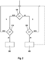
- Fig. 2 is a highly schematic block diagram illustrating an example method for operating a brake system shown.
- the exemplary method relates to the exemplary brake system of Fig. 1 ,
- a predetermined condition B of a critical state of the pressure supply device 5 is present.
- the brake system is in a normal control mode N.
- normal control mode N a termination of the pressure build-up at all to the pressure supply device 5 connected wheel brakes are requested, ie is there a corresponding predetermined braking condition A in block 210 (YES in block 210), the intake valves 6a-6d of the wheel brakes 8-11 are closed in block 300.
- a drive signal is output to the pressure supply device 5, which stops advancing the piston 36 of the pressure supply device 5.
- condition B exists for the print provider 5 (YES in block 100), i. that a critical state of the pressure supply device 5 is given, it is switched to the special control mode S. If the corresponding braking condition A now exists in block 220 (YES in block 220), i. in the special control mode S, a termination of the pressure buildup at all wheel brakes connected to the pressure supply device 5 is requested, then in block 400 the intake valves of the wheel brakes are closed except at least one wheel brake, the so-called selected wheel brake or selected wheel brakes. For each selected wheel brake, the associated inlet valve is kept open and the associated outlet valve is at least temporarily opened, so that pressure medium volume can be discharged from the pressure supply position device 5 into the pressure medium reservoir 4. Furthermore, in block 400, a drive signal is output to the pressure supply device 5, which stops advancing the piston 36 of the pressure supply device 5.
- a position of the pressure supply device 5 are evaluated, for example, position / position of the piston 36 or the rotor position of the electric motor 35th
- the wheel brakes of a vehicle axle preferably the wheel brakes 8, 9 on the rear axle, are selected wheel brakes.
- block 400 only the intake valves 6c and 6d of the wheel brakes 10 and 11 are closed, while the intake valves 6a and 6b of the selected wheel brakes 8 and 9 remain open and the exhaust valves 7a and 7b of the selected wheel brakes 8 and 9 are opened. That Compared to block 300, in block 400, instead of closing the intake valves 6a, 6b, opening the exhaust valves 7a, 7b of the selected wheel brakes 8, 9 is performed.
- a pressure medium volume estimation is carried out, for example, in block 400, in which it is determined how much pressure medium volume from the pressure supply device 5 is still displaced after the output of the drive signal to complete the advancement of the piston 36 until the piston 36 comes to a standstill.
- the appropriate opening time of the outlet valves or the time to transition to the normal control of the block 300 can be determined, so that it is ensured that sufficient pressure medium volume has flowed into the pressure medium reservoir 4 to a critical pressure in the pressure supply device. 5 to prevent.
- condition B in block 100 becomes repeatedly checks what's in Fig. 2 indicated schematically by the dashed arrow.
- ABS control anti-lock control
- the wheel pressure regulator In order to prevent a pressure rise in the pressure chamber 37 of the pressure supply device 5 which is detrimental to the brake system, the wheel pressure regulator is set into the "burst protection" mode (special control mode S) when a critical operating state of the pressure supply device 5 is detected (presence of the condition B).
- special control mode S special control mode S
- the associated exhaust valves 7a, 7b are opened to the pressure medium volume flow through the inertia of the drive 35 of the pressure supply device 5 is generated and leads to an unwanted increase in pressure to discharge directly into the pressure medium reservoir 4.
- the detection of a critical operating state of the Druckrouseicardi 5 is carried out by the evaluation of the piston speed of the pressure supply device. 5 or the engine speed of the drive 35 of the pressure supply device 5 and optionally the piston position of the pressure supply device. 5
- a stop command is sent to the regulator of the pressure supply device 5 and at the same time activates the special control of the inlet and outlet valves of the "Burstprotection" mode (block 400) in the wheel pressure regulator.
- the pressure medium volume to be vented is estimated on the basis of the expected drive dynamics of the electromechanical actuator and the associated dead time until the stop of the piston 36 and above the switching time (opening times) of the exhaust valves 7a, 7b determined.
- the special control is terminated (block 400) when the estimated pressure medium volume has been drained. Then, the exhaust valves 7a, 7b are closed again and at the same time the intake valves 6a, 6b are switched, i. closed.
- the special control (block 400) or the special control mode S can be ended when the Druckr einseicardi 5 is no longer in a critical area.
- an output of the drive signal to the pressure supply device and a closing of the intake valves are preferably carried out.
- special control mode takes place
- the axle-wise switching of the corresponding valves is done to ensure symmetrical pressure conditions in the wheel brakes of the axle.
Landscapes
- Engineering & Computer Science (AREA)
- Transportation (AREA)
- Mechanical Engineering (AREA)
- Physics & Mathematics (AREA)
- Fluid Mechanics (AREA)
- Regulating Braking Force (AREA)
- Braking Systems And Boosters (AREA)
Claims (10)
- Procédé permettant de faire fonctionner un système de freinage, en particulier à patinage réglable, pour des véhicules automobiles, avec• un dispositif de production de pression (5) à commande électrique, qui est formé par un ensemble cylindre-piston avec au moins une chambre de pression hydraulique (37), dont le piston (36) est déplaçable au moyen d'un actionneur électromécanique (35),• un nombre de freins de roue (8, 9, 10, 11), qui sont respectivement raccordés au dispositif de production de pression (5) par une soupape d'admission (6a - 6d) actionnable électriquement, en particulier ouverte sans courant, et• une soupape d'échappement (7a - 7d) actionnable électriquement, en particulier fermée sans courant, pour au moins un des freins de roue, en particulier pour chacun des freins de roue, au moyen de laquelle le frein de roue peut être raccordé à un réservoir de stockage de fluide sous pression (4), qui se trouve en particulier à la pression atmosphérique,dans lequel dans un mode de régulation normal (N) du système de freinage un déplacement du piston (36) du dispositif de production de pression (5) est terminé par l'envoi d'un signal de commande au dispositif de production de pression et les soupapes d'admission des freins de roue sont fermées, lorsqu'une condition de freinage prédéterminée (A) est présente,
caractérisé en ce que l'on bascule vers un mode de régulation spécial (S) lorsqu'une condition prédéterminée pour le dispositif de production de pression (B) est présente, dans lequel dans le mode de régulation spécial, en présence de la condition de freinage prédéterminée (A), on arrête un déplacement du piston (36) du dispositif de production de pression (5) par l'envoi d'un signal de commande au dispositif de production de pression et pour au moins un frein de roue sélectionné (8, 9) on maintient ouverte la soupape d'admission correspondante (6a, 6b) et on ouvre au moins temporairement la soupape d'échappement correspondante (7a, 7b), tandis que l'on ferme les soupapes d'admission (6c, 6d) des autres freins de roue (10, 11). - Procédé selon la revendication 1, caractérisé en ce que les freins de roue (8, 9) d'un essieu, en particulier d'un essieu arrière, du véhicule automobile, sont des freins de roue sélectionnés, dont les soupapes d'admission ne sont pas fermées et dont les soupapes d'échappement sont au moins temporairement ouvertes.
- Procédé selon la revendication 1 ou 2, caractérisé en ce que l'on procède à une estimation du volume de fluide sous pression, au cours de laquelle on détermine quelle quantité du volume de fluide sous pression est encore refoulée hors du dispositif de production de pression (5) après l'envoi du signal de commande, jusqu'à ce que le piston (36) du dispositif de production de pression (5) se trouve à l'arrêt ou que la condition prédéterminée pour le dispositif de production de pression (B) ne soit plus présente.
- Procédé selon la revendication 3, caractérisé en ce que l'on détermine au moins un temps d'ouverture pour la soupape d'échappement ou pour une des soupapes d'échappement à l'aide du volume de fluide sous pression estimé.
- Procédé selon la revendication 3 ou 4, caractérisé en ce que• on ferme de nouveau la soupape d'échappement du frein de roue sélectionné ou les soupapes d'échappement des freins de roue sélectionnés, et• on ferme la soupape d'admission du frein de roue sélectionné ou les soupapes d'admission des freins de roue sélectionnés,lorsque le volume de fluide sous pression estimé a été évacué par la soupape d'échappement ou par les soupapes d'échappement.
- Procédé selon l'une quelconque des revendications 1 à 5, caractérisé en ce que l'on bascule du mode de régulation spécial (S) vers le mode de régulation normal (N), lorsque la condition prédéterminée pour le dispositif de production de pression (B) n'est plus présente.
- Procédé selon l'une quelconque des revendications 1 à 6, caractérisé en ce que la condition de freinage prédéterminée (A) est une fin d'une montée de pression à chacun des freins de roue, qui est demandée en particulier par une fonction de réglage d'antiblocage du système de freinage.
- Procédé selon l'une quelconque des revendications 1 à 7, caractérisé en ce que la condition prédéterminée pour le dispositif de production de pression (B) est un état de fonctionnement critique du dispositif de production de pression, qui est détecté par la vitesse du dispositif de production de pression.
- Procédé selon la revendication 8, caractérisé en ce que la condition prédéterminée (B) est détectée en outre à l'aide d'une position du dispositif de production de pression.
- Système de freinage pour des véhicules automobiles, avec• un dispositif de production de pression (5) à commande électrique, qui est formé par un ensemble cylindre-piston avec au moins une chambre de pression hydraulique (37), dont le piston (36) est déplaçable au moyen d'un actionneur électromécanique (35),• un nombre de freins de roue (8, 9, 10, 11), qui sont respectivement raccordés au dispositif de production de pression (5) par une soupape d'admission (6a - 6d) actionnable électriquement, en particulier ouverte sans courant, et• une soupape d'échappement (7a - 7d) actionnable électriquement, en particulier fermée sans courant, pour au moins un des freins de roue, en particulier pour chacun des freins de roue, au moyen de laquelle le frein de roue peut être raccordé à un réservoir de stockage de fluide sous pression (4), qui se trouve en particulier à la pression atmosphérique, et• une unité électronique de commande et de régulation (12) pour la commande du dispositif de production de pression (5), des soupapes d'admission (6a - 6d) et des soupapes d'échappement (7a - 7d),caractérisé en ce que l'on exécute dans l'unité de commande et de régulation (12) un procédé selon l'une quelconque des revendications 1 à 9.
Applications Claiming Priority (2)
| Application Number | Priority Date | Filing Date | Title |
|---|---|---|---|
| DE102015201331.6A DE102015201331A1 (de) | 2015-01-27 | 2015-01-27 | Verfahren zum Betrieb einer Bremsanlage sowie Bremsanlage |
| PCT/EP2016/050939 WO2016120115A1 (fr) | 2015-01-27 | 2016-01-19 | Procédé permettant de faire fonctionner un système de freinage et système de freinage dans lequel le procédé est mis en œuvre |
Publications (2)
| Publication Number | Publication Date |
|---|---|
| EP3250423A1 EP3250423A1 (fr) | 2017-12-06 |
| EP3250423B1 true EP3250423B1 (fr) | 2019-03-13 |
Family
ID=55174636
Family Applications (1)
| Application Number | Title | Priority Date | Filing Date |
|---|---|---|---|
| EP16700896.0A Active EP3250423B1 (fr) | 2015-01-27 | 2016-01-19 | Procédé permettant de faire fonctionner un système de freinage et système de freinage dans lequel le procédé est mis en oeuvre |
Country Status (6)
| Country | Link |
|---|---|
| US (1) | US10246067B2 (fr) |
| EP (1) | EP3250423B1 (fr) |
| KR (1) | KR101964536B1 (fr) |
| CN (1) | CN107206996B (fr) |
| DE (1) | DE102015201331A1 (fr) |
| WO (1) | WO2016120115A1 (fr) |
Families Citing this family (12)
| Publication number | Priority date | Publication date | Assignee | Title |
|---|---|---|---|---|
| US10315640B2 (en) * | 2016-12-08 | 2019-06-11 | Robert Bosch Gmbh | Vehicle having brake system and method of operating |
| DE102017214858A1 (de) * | 2017-08-24 | 2019-02-28 | Robert Bosch Gmbh | Verfahren zur Vermeidung einer Überschreitung eines zulässigen Höchstdrucks einer hydraulischen Fremdkraft-Fahrzeugbremsanlage mit Schlupfregelung |
| CN107697057A (zh) * | 2017-10-27 | 2018-02-16 | 北京精密机电控制设备研究所 | 一种小型集成化压力输出式刹车控制装置 |
| DE102017221716A1 (de) * | 2017-12-01 | 2019-06-06 | Continental Teves Ag & Co. Ohg | Bremsanlage für Kraftfahrzeuge sowie Verfahren zum Betreiben einer Bremsanlage |
| DE102018204443A1 (de) * | 2018-03-22 | 2019-09-26 | Robert Bosch Gmbh | Verfahren zur Regelung der Antriebsleistung eines elektronisch ansteuerbaren Motors zum Antrieb eines Druckerzeugers einer schlupfregelbaren Fremdkraftbremsanlage eines Kraftfahrzeugs |
| CN108891403A (zh) * | 2018-07-19 | 2018-11-27 | 宁波拓普智能刹车系统有限公司 | 一种集成式电控制动助力系统 |
| DE102019201536A1 (de) * | 2019-02-07 | 2020-08-13 | Robert Bosch Gmbh | Elektrohydraulische Fremdkraft-Fahrzeugbremsanlage |
| DE102019204904B3 (de) * | 2019-04-05 | 2020-09-03 | Robert Bosch Gmbh | Bremskrafterzeuger und Betriebsverfahren |
| KR102881010B1 (ko) | 2020-11-30 | 2025-11-03 | 현대모비스 주식회사 | 차량의 제동장치 및 그 제동방법 |
| DE102021200697A1 (de) * | 2021-01-27 | 2022-07-28 | Robert Bosch Gesellschaft mit beschränkter Haftung | Verfahren zur Steuerung einer elektronisch schlupfregelbaren Fremdkraftbremsanlage mit redundanter Bremsdruckerzeugung |
| DE102021206269A1 (de) | 2021-06-18 | 2022-12-22 | Robert Bosch Gesellschaft mit beschränkter Haftung | Verfahren und Vorrichtung zum Betreiben eines Bremssystems |
| DE102023201642B4 (de) | 2022-10-27 | 2024-07-25 | Continental Automotive Technologies GmbH | Druckregelung mit Pumpe |
Family Cites Families (11)
| Publication number | Priority date | Publication date | Assignee | Title |
|---|---|---|---|---|
| DE3605220A1 (de) * | 1986-02-19 | 1987-08-20 | Teves Gmbh Alfred | Schlupfgeregelte bremsanlage |
| DE102006013626A1 (de) * | 2005-03-23 | 2006-10-05 | Continental Teves Ag & Co. Ohg | Elektrohydraulische Bremsanlage mit Fahrdynamikregelung |
| DE102010040097A1 (de) * | 2009-09-11 | 2011-03-31 | Continental Teves Ag & Co. Ohg | Bremsanlage für Kraftfahrzeuge |
| DE102011077329A1 (de) * | 2010-07-23 | 2012-01-26 | Continental Teves Ag & Co. Ohg | Verfahren zur Regelung eines elektrohydraulischen Bremssystems sowie elektrohydraulisches Bremssystem |
| JP2012206853A (ja) * | 2011-03-30 | 2012-10-25 | Mitsui Eng & Shipbuild Co Ltd | ヤードクレーンの給電装置 |
| DE102012201515A1 (de) * | 2012-02-02 | 2013-08-08 | Continental Teves Ag & Co. Ohg | Verfahren zum Betrieb einer Bremsanlage für Kraftfahrzeuge sowie Bremsanlage |
| DE102013203589A1 (de) * | 2012-03-06 | 2013-09-12 | Continental Teves Ag & Co. Ohg | Verfahren zum Betreiben einer Bremsanlage sowie Bremsanlage |
| DE102013203594A1 (de) * | 2012-03-06 | 2013-09-12 | Continental Teves Ag & Co. Ohg | Verfahren zum Betreiben einer Bremsanlage für Kraftfahrzeuge sowie Bremsanlage |
| DE102013105377A1 (de) | 2013-05-24 | 2014-11-27 | Ipgate Ag | Betätigungsvorrichtung für eine Fahrzeug-Bremsanlage |
| DE102013210563A1 (de) * | 2013-06-06 | 2014-12-11 | Continental Teves Ag & Co. Ohg | Verfahren zur Steuerung und Regelung eines elektrohydraulischen Bremssystems und Bremssystem |
| DE102013014173A1 (de) * | 2013-08-26 | 2015-02-26 | Lucas Automotive Gmbh | Elektrohydraulische Fahrzeug-Bremsanlage mit elektromechanischem Aktuator und Verfahren zum Betreiben der Bremsanlage |
-
2015
- 2015-01-27 DE DE102015201331.6A patent/DE102015201331A1/de not_active Withdrawn
-
2016
- 2016-01-19 EP EP16700896.0A patent/EP3250423B1/fr active Active
- 2016-01-19 CN CN201680007058.6A patent/CN107206996B/zh active Active
- 2016-01-19 KR KR1020177020892A patent/KR101964536B1/ko active Active
- 2016-01-19 WO PCT/EP2016/050939 patent/WO2016120115A1/fr not_active Ceased
-
2017
- 2017-07-27 US US15/661,928 patent/US10246067B2/en active Active
Non-Patent Citations (1)
| Title |
|---|
| None * |
Also Published As
| Publication number | Publication date |
|---|---|
| WO2016120115A1 (fr) | 2016-08-04 |
| US10246067B2 (en) | 2019-04-02 |
| CN107206996B (zh) | 2019-08-13 |
| US20170320477A1 (en) | 2017-11-09 |
| CN107206996A (zh) | 2017-09-26 |
| DE102015201331A1 (de) | 2016-07-28 |
| EP3250423A1 (fr) | 2017-12-06 |
| KR101964536B1 (ko) | 2019-04-01 |
| KR20170097780A (ko) | 2017-08-28 |
Similar Documents
| Publication | Publication Date | Title |
|---|---|---|
| EP3250423B1 (fr) | Procédé permettant de faire fonctionner un système de freinage et système de freinage dans lequel le procédé est mis en oeuvre | |
| EP3526089B1 (fr) | Systeme de frinage électrorauique et methode de controle | |
| EP3710321B1 (fr) | Procédé de contrôle de la fonctionnalité d'un système de freinage et système de freinage | |
| EP3568328B1 (fr) | Système de freinage pour véhicules automobiles et procédé pour faire fonctionner un système de freinage | |
| EP3094529B1 (fr) | Unité de contrôle de frein et système de frein pour véhicules | |
| EP3265348B1 (fr) | Système de freinage pour véhicules automobiles | |
| EP2822825B1 (fr) | Procédé de fonctionnement d'un système de freinage et appareil de freinage correspondant | |
| EP3094528B1 (fr) | Système de freinage pour véhicules | |
| EP3160807B1 (fr) | Système de freinage pour véhicule à moteur | |
| EP2822822B1 (fr) | Procédé de détermination d'une courbe caractéristique pression-volume d'un frein sur roue | |
| EP2809559B1 (fr) | Procede pour faire fonctionner un systeme de freinage de vehicules à moteur et systeme de freinage | |
| EP0752939B1 (fr) | Procede pour faire fonctionner un systeme d'actionnement de freins a regulation electronique | |
| EP3116758B1 (fr) | Procédé d'étalonnage d'un système de freinage électrohydraulique de véhicule automobile et dispositif d'étalonnage | |
| EP2934961B1 (fr) | Système de freinage électrohydraulique pour véhicule et procédé de fonctionnement | |
| EP3038866B1 (fr) | Système de freinage électrohydraulique de véhicule, muni d'un actionneur électromécanique, et procédé pour faire fonctionner ce système de freinage | |
| DE102016201047A1 (de) | Bremsanlage für Kraftfahrzeuge | |
| EP3419874B1 (fr) | Procédé pour faire fonctionner un système de freinage pour véhicules à moteur et système de freinage | |
| DE102012025423A1 (de) | Elektrohydraulische Fahrzeug-Bremsanlage und Verfahren zum Betreiben derselben | |
| DE102012217825A1 (de) | Kombinierte Bremsanlage für Fahrzeuge sowie Verfahren zu deren Betrieb | |
| EP3353026B1 (fr) | Procédé et système pour contrôler la pression de freinage d'un véhicule | |
| DE102016208564B4 (de) | Verfahren zum Betreiben einer Bremsanlage mit einer Druckbereitstellungseinrichtung und Bremsanlage | |
| DE102010022493B4 (de) | Bremssystem mit einem Bremskraftverstärker sowie Verfahren zur Verwendung eines entsprechenden Bremssystems | |
| DE102014224205A1 (de) | Verfahren zum Betrieb einer Bremsanlage sowie Bremsanlage | |
| DE10141547A1 (de) | Verfahren und Vorrichtung zur Betätigungswunscherkennung für ein Kraftfahrzeug | |
| DE102018200619A1 (de) | Verfahren zum Betreiben einer Bremsanlage für ein Kraftfahrzeug sowie Bremsanlage |
Legal Events
| Date | Code | Title | Description |
|---|---|---|---|
| STAA | Information on the status of an ep patent application or granted ep patent |
Free format text: STATUS: THE INTERNATIONAL PUBLICATION HAS BEEN MADE |
|
| PUAI | Public reference made under article 153(3) epc to a published international application that has entered the european phase |
Free format text: ORIGINAL CODE: 0009012 |
|
| STAA | Information on the status of an ep patent application or granted ep patent |
Free format text: STATUS: REQUEST FOR EXAMINATION WAS MADE |
|
| 17P | Request for examination filed |
Effective date: 20170828 |
|
| AK | Designated contracting states |
Kind code of ref document: A1 Designated state(s): AL AT BE BG CH CY CZ DE DK EE ES FI FR GB GR HR HU IE IS IT LI LT LU LV MC MK MT NL NO PL PT RO RS SE SI SK SM TR |
|
| AX | Request for extension of the european patent |
Extension state: BA ME |
|
| DAV | Request for validation of the european patent (deleted) | ||
| DAX | Request for extension of the european patent (deleted) | ||
| RAP1 | Party data changed (applicant data changed or rights of an application transferred) |
Owner name: CONTINENTAL TEVES AG & CO. OHG |
|
| GRAP | Despatch of communication of intention to grant a patent |
Free format text: ORIGINAL CODE: EPIDOSNIGR1 |
|
| STAA | Information on the status of an ep patent application or granted ep patent |
Free format text: STATUS: GRANT OF PATENT IS INTENDED |
|
| INTG | Intention to grant announced |
Effective date: 20180928 |
|
| GRAS | Grant fee paid |
Free format text: ORIGINAL CODE: EPIDOSNIGR3 |
|
| GRAA | (expected) grant |
Free format text: ORIGINAL CODE: 0009210 |
|
| STAA | Information on the status of an ep patent application or granted ep patent |
Free format text: STATUS: THE PATENT HAS BEEN GRANTED |
|
| AK | Designated contracting states |
Kind code of ref document: B1 Designated state(s): AL AT BE BG CH CY CZ DE DK EE ES FI FR GB GR HR HU IE IS IT LI LT LU LV MC MK MT NL NO PL PT RO RS SE SI SK SM TR |
|
| REG | Reference to a national code |
Ref country code: GB Ref legal event code: FG4D Free format text: NOT ENGLISH |
|
| REG | Reference to a national code |
Ref country code: CH Ref legal event code: EP Ref country code: AT Ref legal event code: REF Ref document number: 1107291 Country of ref document: AT Kind code of ref document: T Effective date: 20190315 |
|
| REG | Reference to a national code |
Ref country code: IE Ref legal event code: FG4D Free format text: LANGUAGE OF EP DOCUMENT: GERMAN |
|
| REG | Reference to a national code |
Ref country code: DE Ref legal event code: R096 Ref document number: 502016003714 Country of ref document: DE |
|
| REG | Reference to a national code |
Ref country code: NL Ref legal event code: MP Effective date: 20190313 |
|
| REG | Reference to a national code |
Ref country code: LT Ref legal event code: MG4D |
|
| PG25 | Lapsed in a contracting state [announced via postgrant information from national office to epo] |
Ref country code: FI Free format text: LAPSE BECAUSE OF FAILURE TO SUBMIT A TRANSLATION OF THE DESCRIPTION OR TO PAY THE FEE WITHIN THE PRESCRIBED TIME-LIMIT Effective date: 20190313 Ref country code: NO Free format text: LAPSE BECAUSE OF FAILURE TO SUBMIT A TRANSLATION OF THE DESCRIPTION OR TO PAY THE FEE WITHIN THE PRESCRIBED TIME-LIMIT Effective date: 20190613 Ref country code: LT Free format text: LAPSE BECAUSE OF FAILURE TO SUBMIT A TRANSLATION OF THE DESCRIPTION OR TO PAY THE FEE WITHIN THE PRESCRIBED TIME-LIMIT Effective date: 20190313 Ref country code: SE Free format text: LAPSE BECAUSE OF FAILURE TO SUBMIT A TRANSLATION OF THE DESCRIPTION OR TO PAY THE FEE WITHIN THE PRESCRIBED TIME-LIMIT Effective date: 20190313 |
|
| PG25 | Lapsed in a contracting state [announced via postgrant information from national office to epo] |
Ref country code: LV Free format text: LAPSE BECAUSE OF FAILURE TO SUBMIT A TRANSLATION OF THE DESCRIPTION OR TO PAY THE FEE WITHIN THE PRESCRIBED TIME-LIMIT Effective date: 20190313 Ref country code: RS Free format text: LAPSE BECAUSE OF FAILURE TO SUBMIT A TRANSLATION OF THE DESCRIPTION OR TO PAY THE FEE WITHIN THE PRESCRIBED TIME-LIMIT Effective date: 20190313 Ref country code: BG Free format text: LAPSE BECAUSE OF FAILURE TO SUBMIT A TRANSLATION OF THE DESCRIPTION OR TO PAY THE FEE WITHIN THE PRESCRIBED TIME-LIMIT Effective date: 20190613 Ref country code: GR Free format text: LAPSE BECAUSE OF FAILURE TO SUBMIT A TRANSLATION OF THE DESCRIPTION OR TO PAY THE FEE WITHIN THE PRESCRIBED TIME-LIMIT Effective date: 20190614 Ref country code: HR Free format text: LAPSE BECAUSE OF FAILURE TO SUBMIT A TRANSLATION OF THE DESCRIPTION OR TO PAY THE FEE WITHIN THE PRESCRIBED TIME-LIMIT Effective date: 20190313 Ref country code: NL Free format text: LAPSE BECAUSE OF FAILURE TO SUBMIT A TRANSLATION OF THE DESCRIPTION OR TO PAY THE FEE WITHIN THE PRESCRIBED TIME-LIMIT Effective date: 20190313 |
|
| PG25 | Lapsed in a contracting state [announced via postgrant information from national office to epo] |
Ref country code: ES Free format text: LAPSE BECAUSE OF FAILURE TO SUBMIT A TRANSLATION OF THE DESCRIPTION OR TO PAY THE FEE WITHIN THE PRESCRIBED TIME-LIMIT Effective date: 20190313 Ref country code: PT Free format text: LAPSE BECAUSE OF FAILURE TO SUBMIT A TRANSLATION OF THE DESCRIPTION OR TO PAY THE FEE WITHIN THE PRESCRIBED TIME-LIMIT Effective date: 20190713 Ref country code: AL Free format text: LAPSE BECAUSE OF FAILURE TO SUBMIT A TRANSLATION OF THE DESCRIPTION OR TO PAY THE FEE WITHIN THE PRESCRIBED TIME-LIMIT Effective date: 20190313 Ref country code: SK Free format text: LAPSE BECAUSE OF FAILURE TO SUBMIT A TRANSLATION OF THE DESCRIPTION OR TO PAY THE FEE WITHIN THE PRESCRIBED TIME-LIMIT Effective date: 20190313 Ref country code: CZ Free format text: LAPSE BECAUSE OF FAILURE TO SUBMIT A TRANSLATION OF THE DESCRIPTION OR TO PAY THE FEE WITHIN THE PRESCRIBED TIME-LIMIT Effective date: 20190313 Ref country code: RO Free format text: LAPSE BECAUSE OF FAILURE TO SUBMIT A TRANSLATION OF THE DESCRIPTION OR TO PAY THE FEE WITHIN THE PRESCRIBED TIME-LIMIT Effective date: 20190313 Ref country code: EE Free format text: LAPSE BECAUSE OF FAILURE TO SUBMIT A TRANSLATION OF THE DESCRIPTION OR TO PAY THE FEE WITHIN THE PRESCRIBED TIME-LIMIT Effective date: 20190313 |
|
| PG25 | Lapsed in a contracting state [announced via postgrant information from national office to epo] |
Ref country code: SM Free format text: LAPSE BECAUSE OF FAILURE TO SUBMIT A TRANSLATION OF THE DESCRIPTION OR TO PAY THE FEE WITHIN THE PRESCRIBED TIME-LIMIT Effective date: 20190313 Ref country code: PL Free format text: LAPSE BECAUSE OF FAILURE TO SUBMIT A TRANSLATION OF THE DESCRIPTION OR TO PAY THE FEE WITHIN THE PRESCRIBED TIME-LIMIT Effective date: 20190313 |
|
| REG | Reference to a national code |
Ref country code: DE Ref legal event code: R097 Ref document number: 502016003714 Country of ref document: DE |
|
| PG25 | Lapsed in a contracting state [announced via postgrant information from national office to epo] |
Ref country code: IS Free format text: LAPSE BECAUSE OF FAILURE TO SUBMIT A TRANSLATION OF THE DESCRIPTION OR TO PAY THE FEE WITHIN THE PRESCRIBED TIME-LIMIT Effective date: 20190713 |
|
| PLBE | No opposition filed within time limit |
Free format text: ORIGINAL CODE: 0009261 |
|
| STAA | Information on the status of an ep patent application or granted ep patent |
Free format text: STATUS: NO OPPOSITION FILED WITHIN TIME LIMIT |
|
| PG25 | Lapsed in a contracting state [announced via postgrant information from national office to epo] |
Ref country code: DK Free format text: LAPSE BECAUSE OF FAILURE TO SUBMIT A TRANSLATION OF THE DESCRIPTION OR TO PAY THE FEE WITHIN THE PRESCRIBED TIME-LIMIT Effective date: 20190313 |
|
| 26N | No opposition filed |
Effective date: 20191216 |
|
| PG25 | Lapsed in a contracting state [announced via postgrant information from national office to epo] |
Ref country code: SI Free format text: LAPSE BECAUSE OF FAILURE TO SUBMIT A TRANSLATION OF THE DESCRIPTION OR TO PAY THE FEE WITHIN THE PRESCRIBED TIME-LIMIT Effective date: 20190313 |
|
| PG25 | Lapsed in a contracting state [announced via postgrant information from national office to epo] |
Ref country code: TR Free format text: LAPSE BECAUSE OF FAILURE TO SUBMIT A TRANSLATION OF THE DESCRIPTION OR TO PAY THE FEE WITHIN THE PRESCRIBED TIME-LIMIT Effective date: 20190313 |
|
| PG25 | Lapsed in a contracting state [announced via postgrant information from national office to epo] |
Ref country code: MC Free format text: LAPSE BECAUSE OF FAILURE TO SUBMIT A TRANSLATION OF THE DESCRIPTION OR TO PAY THE FEE WITHIN THE PRESCRIBED TIME-LIMIT Effective date: 20190313 |
|
| REG | Reference to a national code |
Ref country code: CH Ref legal event code: PL |
|
| GBPC | Gb: european patent ceased through non-payment of renewal fee |
Effective date: 20200119 |
|
| REG | Reference to a national code |
Ref country code: BE Ref legal event code: MM Effective date: 20200131 |
|
| PG25 | Lapsed in a contracting state [announced via postgrant information from national office to epo] |
Ref country code: GB Free format text: LAPSE BECAUSE OF NON-PAYMENT OF DUE FEES Effective date: 20200119 Ref country code: LU Free format text: LAPSE BECAUSE OF NON-PAYMENT OF DUE FEES Effective date: 20200119 |
|
| PG25 | Lapsed in a contracting state [announced via postgrant information from national office to epo] |
Ref country code: CH Free format text: LAPSE BECAUSE OF NON-PAYMENT OF DUE FEES Effective date: 20200131 Ref country code: LI Free format text: LAPSE BECAUSE OF NON-PAYMENT OF DUE FEES Effective date: 20200131 Ref country code: BE Free format text: LAPSE BECAUSE OF NON-PAYMENT OF DUE FEES Effective date: 20200131 |
|
| PG25 | Lapsed in a contracting state [announced via postgrant information from national office to epo] |
Ref country code: IE Free format text: LAPSE BECAUSE OF NON-PAYMENT OF DUE FEES Effective date: 20200119 |
|
| REG | Reference to a national code |
Ref country code: AT Ref legal event code: MM01 Ref document number: 1107291 Country of ref document: AT Kind code of ref document: T Effective date: 20210119 |
|
| PG25 | Lapsed in a contracting state [announced via postgrant information from national office to epo] |
Ref country code: AT Free format text: LAPSE BECAUSE OF NON-PAYMENT OF DUE FEES Effective date: 20210119 |
|
| PG25 | Lapsed in a contracting state [announced via postgrant information from national office to epo] |
Ref country code: MT Free format text: LAPSE BECAUSE OF FAILURE TO SUBMIT A TRANSLATION OF THE DESCRIPTION OR TO PAY THE FEE WITHIN THE PRESCRIBED TIME-LIMIT Effective date: 20190313 Ref country code: CY Free format text: LAPSE BECAUSE OF FAILURE TO SUBMIT A TRANSLATION OF THE DESCRIPTION OR TO PAY THE FEE WITHIN THE PRESCRIBED TIME-LIMIT Effective date: 20190313 |
|
| PG25 | Lapsed in a contracting state [announced via postgrant information from national office to epo] |
Ref country code: MK Free format text: LAPSE BECAUSE OF FAILURE TO SUBMIT A TRANSLATION OF THE DESCRIPTION OR TO PAY THE FEE WITHIN THE PRESCRIBED TIME-LIMIT Effective date: 20190313 |
|
| REG | Reference to a national code |
Ref country code: DE Ref legal event code: R081 Ref document number: 502016003714 Country of ref document: DE Owner name: CONTINENTAL AUTOMOTIVE TECHNOLOGIES GMBH, DE Free format text: FORMER OWNER: CONTINENTAL TEVES AG & CO. OHG, 60488 FRANKFURT, DE Ref country code: DE Ref legal event code: R081 Ref document number: 502016003714 Country of ref document: DE Owner name: AUMOVIO GERMANY GMBH, DE Free format text: FORMER OWNER: CONTINENTAL TEVES AG & CO. OHG, 60488 FRANKFURT, DE |
|
| P01 | Opt-out of the competence of the unified patent court (upc) registered |
Effective date: 20230522 |
|
| REG | Reference to a national code |
Ref country code: DE Ref legal event code: R081 Ref document number: 502016003714 Country of ref document: DE Owner name: CONTINENTAL AUTOMOTIVE TECHNOLOGIES GMBH, DE Free format text: FORMER OWNER: CONTINENTAL AUTOMOTIVE TECHNOLOGIES GMBH, 30165 HANNOVER, DE Ref country code: DE Ref legal event code: R081 Ref document number: 502016003714 Country of ref document: DE Owner name: AUMOVIO GERMANY GMBH, DE Free format text: FORMER OWNER: CONTINENTAL AUTOMOTIVE TECHNOLOGIES GMBH, 30165 HANNOVER, DE |
|
| REG | Reference to a national code |
Ref country code: DE Ref legal event code: R081 Ref document number: 502016003714 Country of ref document: DE Owner name: AUMOVIO GERMANY GMBH, DE Free format text: FORMER OWNER: CONTINENTAL AUTOMOTIVE TECHNOLOGIES GMBH, 30175 HANNOVER, DE |
|
| PGFP | Annual fee paid to national office [announced via postgrant information from national office to epo] |
Ref country code: DE Payment date: 20260131 Year of fee payment: 11 |
|
| PGFP | Annual fee paid to national office [announced via postgrant information from national office to epo] |
Ref country code: IT Payment date: 20260123 Year of fee payment: 11 |
|
| PGFP | Annual fee paid to national office [announced via postgrant information from national office to epo] |
Ref country code: FR Payment date: 20260126 Year of fee payment: 11 |