EP3250806B1 - Kolben mit abgedichtetem kühlkanal und verfahren zur konstruktion davon - Google Patents
Kolben mit abgedichtetem kühlkanal und verfahren zur konstruktion davon Download PDFInfo
- Publication number
- EP3250806B1 EP3250806B1 EP16706278.5A EP16706278A EP3250806B1 EP 3250806 B1 EP3250806 B1 EP 3250806B1 EP 16706278 A EP16706278 A EP 16706278A EP 3250806 B1 EP3250806 B1 EP 3250806B1
- Authority
- EP
- European Patent Office
- Prior art keywords
- opening
- piston
- floor
- cooling gallery
- sealing member
- Prior art date
- Legal status (The legal status is an assumption and is not a legal conclusion. Google has not performed a legal analysis and makes no representation as to the accuracy of the status listed.)
- Active
Links
Images


Classifications
-
- F—MECHANICAL ENGINEERING; LIGHTING; HEATING; WEAPONS; BLASTING
- F02—COMBUSTION ENGINES; HOT-GAS OR COMBUSTION-PRODUCT ENGINE PLANTS
- F02F—CYLINDERS, PISTONS OR CASINGS, FOR COMBUSTION ENGINES; ARRANGEMENTS OF SEALINGS IN COMBUSTION ENGINES
- F02F3/00—Pistons
- F02F3/16—Pistons having cooling means
- F02F3/18—Pistons having cooling means the means being a liquid or solid coolant, e.g. sodium, in a closed chamber in piston
-
- F—MECHANICAL ENGINEERING; LIGHTING; HEATING; WEAPONS; BLASTING
- F02—COMBUSTION ENGINES; HOT-GAS OR COMBUSTION-PRODUCT ENGINE PLANTS
- F02F—CYLINDERS, PISTONS OR CASINGS, FOR COMBUSTION ENGINES; ARRANGEMENTS OF SEALINGS IN COMBUSTION ENGINES
- F02F3/00—Pistons
- F02F3/0015—Multi-part pistons
- F02F3/003—Multi-part pistons the parts being connected by casting, brazing, welding or clamping
-
- F—MECHANICAL ENGINEERING; LIGHTING; HEATING; WEAPONS; BLASTING
- F02—COMBUSTION ENGINES; HOT-GAS OR COMBUSTION-PRODUCT ENGINE PLANTS
- F02F—CYLINDERS, PISTONS OR CASINGS, FOR COMBUSTION ENGINES; ARRANGEMENTS OF SEALINGS IN COMBUSTION ENGINES
- F02F3/00—Pistons
- F02F3/0015—Multi-part pistons
- F02F3/003—Multi-part pistons the parts being connected by casting, brazing, welding or clamping
- F02F2003/0061—Multi-part pistons the parts being connected by casting, brazing, welding or clamping by welding
Definitions
- This invention relates generally to internal combustion engines, and more particularly to pistons and their method of construction.
- the outer cooling galleries typically circulate about an upper land of the piston including a ring groove region while the inner cooling gallery is typically beneath an upper combustion surface of the piston head, commonly referred to as undercrown, which commonly includes a recessed combustion bowl.
- undercrown which commonly includes a recessed combustion bowl.
- both the ring belt region and the combustion surface benefit from cooling action of the circulated oil.
- a closed cooling gallery is provided, it is known to cast closed cooling galleries; however, the manufacturing process tends to be costly.
- JP S61 187 944 U discloses a piston of an internal combustion engine having a sealing cavity formed therein between a combustion chamber side wall and a piston outer wall, said cavity enclosing oil and an active gas.
- the sealing cavity is formed by core molding, wherein an opening is sealed with a drain bolt via a gasket.
- JP S61187944 U does not disclose a piston body with an upper and a lower part constructed as separate pieces, wherein the lower part provides a floor of an annular cooling gallery and a floor has a through opening.
- US 2014/0123930 A1 discloses a piston for an internal combustion engine comprises a sealed cooling gallery extending circumferentially around a center axis beneath a bowl rim of an upper crown.
- a metal-containing composition having a high thermal conductivity fills a portion of the sealed cooling gallery to dissipate heat.
- the metal-containing composition includes a base material having a melting temperature less than 181°C. and a plurality of metal particles having a thermal conductivity greater than the thermal conductivity of the base material.
- the metal-containing composition can comprise copper particles dispersed in silicone oil, or copper particles dispersed in a mixture of alkali metals.
- a similar piston assembly is also disclosed in FR 647 110 A .
- a piston constructed in accordance with this invention overcomes the aforementioned disadvantages associated with pistons having a closed cooling gallery.
- a piston for an internal combustion engine according to the present invention is defined by claim 1.
- Dependent claims relate to preferred embodiments.
- a method of constructing a piston for an internal combustion engine according to the present invention is defined by claim 4.
- Claim 5 relates to preferred embodiments.
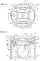
- Figures 1 and 2 illustrate a piston assembly, referred to hereafter simply as piston 10, constructed according to one presently preferred embodiment of the invention, for reciprocating movement in a cylinder bore or chamber of an internal combustion engine (not shown), such as light vehicle diesel, midrange diesel, heavy duty and large bore diesel engines, and gas engines, for example.
- the piston 10 has a piston body 12 extending along a central longitudinal axis 14 along which the piston 10 reciprocates in the cylinder bore.
- the body 12 is formed including an upper combustion wall having on one side an upper combustion surface 16 configured for direct exposure to combustion gases within a cylinder bore and on an opposite side an undercrown surface 18 located directly and axially beneath the upper combustion surface 16.
- the piston body 12 is also formed having a ring belt region 20 depending from the upper combustion surface 16 adjacent the upper combustion surface 16 wherein the ring belt region 20 is configured for receipt of at least one piston ring (not shown), as is known. Further, the piston body 12 is constructed having an annular, closed and sealed cooling gallery 22 with a coolant medium 24 sealed therein for the life of the piston 10.
- the cooling gallery 22 is shown as being toroid-shaped and configured radially inwardly and in substantial radial alignment with the ring belt region 20, by way of example and without limitation.
- the cooling gallery 22 Upon disposing the coolant medium 24 within the cooling gallery 22, the cooling gallery 22 is sealed off and maintained as a hermetically sealed cooling gallery by a sealing member 26, thereby assuring the coolant medium 24 is contained within the cooling gallery 22 and prevented from leaking outwardly therefrom past the sealing member 26.
- the piston body 12 is shown having a steel upper part 28 and a steel lower part 30 constructed from separate pieces of steel material and subsequently fixed to one another via a welding process, such as induction welding, resistance welding, charge carrier rays, electron beam welding, laser welding, stir welding, brazing, soldering, hot or cold diffusion, and shown as a friction welding process, though other joining processes are contemplated to be within the scope of the invention.
- a welding process such as induction welding, resistance welding, charge carrier rays, electron beam welding, laser welding, stir welding, brazing, soldering, hot or cold diffusion, and shown as a friction welding process, though other joining processes are contemplated to be within the scope of the invention.
- a first bond joint 32 joins a pair of annular inner ribs 34, 36 to one another
- a second bond joint 38 extends through an outer wall within the ring belt region 20 to join a pair of annular outer ribs 40, 42 to one another.
- the lower part 30 depends along the central axis 14 from the upper part 28 to provide a pair of pin bosses 44 having laterally spaced pin bores 46 coaxially aligned along a pin bore axis 48 that extends generally transverse to the central longitudinal axis 14.
- the pin bosses 44 are joined to laterally spaced skirt portions 50 via strut portions 52.
- the skirt portions 50 are diametrically spaced from one another across opposite sides the pin bore axis 48 and have convex outer surfaces contoured for sliding cooperation within the cylinder bore to maintain the piston 10 in a desired orientation as it reciprocates along the axis 14 through the cylinder bore.
- the upper combustion surface 16 is represented as having a recessed combustion bowl 54 to provide a desired gas flow with the cylinder bore. At least in part due to the combustion bowl 54, relatively thin regions of piston body material are formed between the upper combustion surface 16, the annular cooling gallery 22 and the undercrown surface 18. As such, in use, these regions need to be properly cooled via oil flowing through the cooling gallery 22. The necessary cooling for this region is provided, at least in part, via coolant medium 24 contained within the cooling gallery 22.
- the lower part 30 has a through opening 56 formed in a floor 58 of the cooling gallery 22, such as via a drilling process, by way of example and without limitation.
- the through opening 56 can be formed having a suitable diameter, and in accordance with one example, the diameter was formed between about 8-10mm, without limitation, and formed as non-threaded through opening.
- the through opening 56 is shown as being located radially inwardly from a central portion of one of the skirts 50, generally centrally between the pin bores 46, on a non-thrust side of the piston 10, thereby being in a region of reduced stress.
- an identifying feature can be formed in a surface of the floor 58, such as an embossed or coined depression, by way of example and without limitation, while forging or otherwise constructing the lower part 30. Then, upon disposing the desired type and amount of coolant medium 24 through the through opening 56 and into the cooling gallery 22, the cooling gallery 22 is completely closed and sealed off via the sealing member 26 and confined within the cooling gallery 22.
- FIGS 4A-B depict an embodiment, wherein the sealing member 26 is provided as a non-threaded, steel plug.
- the plug 26 has a generally cylindrical stud or shank 60 extending along a central axis 61 and an enlarged head, also referred to as end cap 62.
- the shank 60 is preferably sized having an outer diameter (d) that is less than the diameter of the through opening 56 in the floor 58 of the cooling gallery 22, and thus, the shank 60, being void of any external male threads, has a clearance fit within the through opening 56 upon being disposed therethrough.
- the shank 60 can be formed having a chamfered end 64.
- the end cap 62 is formed having a planar or substantially planar, annular joining surface 66 extending generally transversely to the axis 61 outwardly from the shank 60.
- the joining surface 66 extends radially outwardly beyond the through opening 56, thereby presenting the end cap 62 with a diameter that is larger than the diameter of the through opening 56.
- the joining surface is the portion of the sealing member 26 that is responsible for and directly forms a fixed bond joint with the lower part 30.
- a bonding surface 70 on the underside of the floor 58, to which the joining surface 66 of the sealing member 26 is to be fixed can be machined flat and planar, such as in a spot facing operation, by way of example and without limitation. As such, a good, reliable, gas/fluid leak-proof bond is able to be reliably established between the joining surface 66 and the bonding surface 70.
- the shank 60 of the sealing member 26 is disposed within the through opening 56 in a clearance fit therewith, and the sealing member 26 is rotatably driven at a sufficiently high rotational speed to form the bond joint 68 via a friction weld, whereupon flashing 71 is formed to extend radially outwardly from the respective steel joining and bonding surfaces 66, 70 and axially inwardly into the through opening 56, which is accommodated by the clearance fit of the shank 60 within the through opening 56.
- the flashing 71 being freely permitted to flow into the through opening 56 between the outer periphery of the through opening 56 and the outer surface of the shank 60, automatically facilitates forming the gas/liquid tight seal to hermetically seal off the through opening 56, and thus, no additional bonding agents are needed, thereby further providing manufacturing efficiencies, thus, reducing cost.
- the end cap 62 can be provided with a drive feature 72, shown as a non-circular, hexagonal recessed pocket, by way of example and without limitation, for receipt of a similarly shaped drive tool. It should be recognized that the pocket 72 could take a different; non-circular shaped, as desired, and further, could be formed as a male protrusion, if desired.
- FIGS 5A-5B and 6A-6B depict an embodiment, wherein a sealing member 26' for closing and sealing off a through opening 56 extending into a cooling gallery 22 of a piston (portion of piston 10 illustrated), wherein the same reference numerals, offset by a prime symbol ('), are used to identify like features of the sealing member.
- the sealing member 26' is provided as a non-threaded, steel plug.
- the plug 26' has an annular tapered nose 60' extending radially inwardly toward a central axis 61' to a free end 64', wherein the free end 64' is shown to be slightly flattened, by way of example and without limitation.
- the tapered nose 60' extends radially outwardly away from the central axis 61' to a generally cylindrical sidewall 63, wherein the sidewall 63 extends to an opposite free end 62'.
- the free end 62' can be provided with a drive feature 72', shown as a serrated face, by way of example and without limitation, for receipt of a similarly serrated drive tool 73.
- a central recessed pocket 75 can be formed in the free end 62' to receive a similarly shaped male protrusion 77 on the driving tool 73.
- the tapered nose 60' provides a conical joining surface 66' that extends radially outwardly beyond the through opening 56, thereby presenting the sidewall 63 and joining surface 66' with a diameter that is larger than the diameter of the through opening 56.
- the joining surface 66' is the portion of the sealing member 26' that is responsible for abutting and directly forming a fixed friction welded bond joint 68' with the lower part 30.
- the tapered nose 60' of the sealing member 26' is disposed within the through opening 56, wherein the conical or frustroconical form of the nose taper facilitates locating and centering the sealing member 26' in the through opening 56.
- the serrated tool 73 is brought into mating engagement with the serrated drive feature 72', and the sealing member 26' is rotatably driven at a sufficiently high rotational speed to form the bond joint 68' via a friction weld, whereupon the sealing member 26' is caused to sink into the material of the floor 58 as a result of melting material of the floor 58, wherein molten, solidified and hardened flashing 71' is formed to extend radially outwardly from the respective steel joining and bonding surfaces 66', 70 and axially inwardly into the through opening 56, which facilitates forming the strong, gas/liquid tight seal to hermetically seal off the through opening 56, and thus, no additional bonding agents are needed, thereby further providing manufacturing efficiencies, thus, reducing cost.
- Figures 7A and 7B depict an assembly with a sealing member 126 for closing and sealing off a through opening 156 extending into a cooling gallery 122 of a piston (portion of piston 110 illustrated) that is not covered by the appended claims.
- This assembly is included for explanatory purposes, wherein the same reference numerals, offset by a factor of 100, are used to identify like features.
- the piston body 112 is constructed substantially the same as discussed above for the body 12, and thus, repetition in describing the piston body 112 is believed unnecessary.
- the sealing member 126 is provided as a rivet-style member, having a rivet body 74 and a rivet actuation member, also referred to as rivet mandrel 76.
- the rivet-style sealing member 126 is thus actuated to move from a first pre-installed state ( Figure 7A ) to an expanded, plastically deformed second installed state ( Figure 7B ) in the same manner as a common rivet.
- a shank 78 of the rivet body 74 is inserted through the non-threaded through opening 156 in a slight clearance fit, whereupon a portion of the shank 78 is extended upwardly into the cooling gallery 122 and an enlarged cap or head 79, having a larger diameter than the through opening 156, is brought into abutment with an underside of the floor 158, and then, a suitable rivet actuation tool (not shown) grasps the exposed, free end of the rivet mandrel 76 depending from the floor 158 to pull the rivet mandrel 76 relative to the rivet body 74, as is known in deploying rivets, thereby plastically deforming and expanding a portion of the shank 78 of the rivet body 74 into a permanent interference fit with an outer periphery of the through opening 156 an upper surface of the floor 158 to sealingly close off the through opening 156.
- a high temperature anaerobic sealant material 82 could be disposed about the shank 78 of the rivet body 74 prior to disposing the rivet body 74 into the through opening 156.
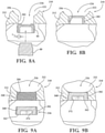
- Figures 8A and 8B depict an assembly with a sealing member 226 for closing off a through opening 256 extending into a cooling gallery 222 of a piston (portion of piston 210 illustrated) that is not covered by the appended claims.
- the assembly is included for explanatory purposes, wherein the same reference numerals, offset by a factor of 200, are used to identify like features.
- the piston body 212 is constructed substantially the same as discussed above for the body 12, and thus, repetition in describing the piston body is believed unnecessary.
- the sealing member 226 is provided as a cup-shaped plug. During installation, a closed end of the plug 226 is pressed into the through opening 256 in an interference fit with a suitable installation tool 80 received in and pressing against an open end of the plug 226 to sealingly close off the through opening 256.
- a high temperature anaerobic sealant material 282 is first disposed about an outer periphery 84 of the plug 226 prior to disposing the plug 226 into the through opening 256.
- the plug 226 can be formed having any suitable diameter to provide the desired interference fit within the through opening 256, taking into account the material and wall thickness (t) of the plug 226.
- Figures 9A and 9B depict an assembly with a tapered sealing member 326 for closing and sealing off a through opening 356 extending into a cooling gallery 322 of a piston (portion of piston 310 illustrated) that is not covered by the appended claims
- the assembly is included for explanatory purposes, wherein the same reference numerals, offset by a factor of 300, are used to identify like features.
- the piston body 312 is constructed substantially the same as discussed above for the body 12, and thus, repetition in describing the piston body 312 is believed unnecessary.
- the tapered sealing member 326 is provided as a tapered threaded member, having a tapered male threaded shank 360.
- the tapered threaded shank 360 is threaded into a matching tapered female threaded through opening 356 to sealingly close off the tapered threaded through opening 356.
- the matching inclination of the tapers of the threaded shank 360 and the threaded opening 356 automatically cause the sealing member 326 to be driven to a set depth, and prevent the sealing member 326 from being over driven completely through the through opening 356.
- a high temperature anaerobic sealant material 382 is first disposed about an outer periphery of the threaded shank 360 prior to threading the threaded shank 360 into the threaded through opening 356.
- an end 362 of the member 326 can be provided with a drive feature 372, shown as a non-circular, hexagonal recessed pocket, by way of example and without limitation, for receipt of a similarly shaped drive tool.
- the pocket 372 could take a different; non-circular shaped, as desired, and further, could be formed as a male protrusion, if desired.
- the tapered threaded shank 360 is threaded into the tapered threaded through opening 356 to a torque between about 18-22 Nm, which has been found, in combination with the anaerobic sealant material 382, to optimally close off and seal the through opening 356 for the intended life of the piston 310.
Landscapes
- Engineering & Computer Science (AREA)
- Chemical & Material Sciences (AREA)
- Combustion & Propulsion (AREA)
- Mechanical Engineering (AREA)
- General Engineering & Computer Science (AREA)
- Pistons, Piston Rings, And Cylinders (AREA)
Claims (5)
- Kolben für einen Verbrennungsmotor, umfassend:einen Kolbenkörper (12), der ein oberes Teil (28) und ein unteres Teil (30) beinhaltet, die eine ringförmige Kühlgalerie (22) begrenzen, wobei das obere Teil (28) und das untere Teil (30) aus separaten Stücken konstruiert sind und durch einen Schweißprozess aneinander befestigt werden, das obere Teil (28) eine obere Verbrennungsfläche (16), die für eine direkte Einwirkung von Verbrennungsgasen ausgelegt ist, innerhalb einer Zylinderbohrung und eine Unterbodenfläche (18) unterhalb der oberen Verbrennungsfläche (16) aufweist und einen Ringbandbereich (20) radial außerhalb der ringförmigen Kühlgalerie (22) aufweist, wobei das untere Teil (30) einen Boden (58) der ringförmigen Kühlgalerie (22) und ein Paar von Kolbenbolzenaugen (44), die von dem Boden (58) herabhängen, bereitstellt, wobei die Kolbenbolzenaugen (44) radial ausgerichtete Kolbenbolzenbohrungen (46) aufweisen und der Boden (58) eine Durchgangsöffnung (56) hat;ein Kühlmedium (24), das in der ringförmigen Kühlgalerie (22) angeordnet ist; undein Dichtungselement (26), das die Durchgangsöffnung (56) abdichtet und das Kühlmedium (24) in der Kühlgalerie (22) abdichtet;wobei das Dichtungselement (26) an dem Boden (58) durch eine Reibschweißverbindung befestigt ist, das Dichtungselement (26) eine sich konisch verjüngende Nase (60'), die in der Durchgangsöffnung (56) angeordnet ist, eine Verbindungsfläche (66'), die an einer Bindungsfläche (70) an einer Unterseite des Bodens (58) befestigt ist, und gehärtete Verblechung, die sich von der Verbindungs- und Bindungsfläche (66', 70) radial nach außen und axial nach innen in die Durchgangsöffnung (56) erstreckt, aufweist.
- Kolben nach Anspruch 1, wobei die Durchgangsöffnung (56) an einer Nicht-Schubseite des Kolbenkörpers (12) gebildet ist.
- Kolben nach Anspruch 2, wobei die Durchgangsöffnung (56) im Allgemeinen zwischen den Kolbenbolzenaugen (44) gebildet ist.
- Verfahren zum Konstruieren eines Kolbens für einen Verbrennungsmotor, umfassend:Bilden eines Kolbenkörpers (12), der ein oberes Teil (28) und ein unteres Teil (30) beinhaltet, die aus separaten Stücken konstruiert sind, wobei das obere Teil (26) eine obere Verbrennungsfläche (16), die für eine direkte Einwirkung von Verbrennungsgasen ausgelegt ist, innerhalb einer Zylinderbohrung und eine Unterbodenfläche (18) unterhalb der oberen Verbrennungsfläche (16) aufweist;Bilden eines Ringbandbereichs (20), der zum Aufnehmen mindestens eines Kolbenrings neben der oberen Verbrennungsfläche (16) ausgelegt ist;Bilden einer ringförmigen Kühlgalerie (22) radial einwärts von dem Ringbandbereich (20), wobei die ringförmige Kühlgalerie (22) einen Boden (58) aufweist, wobei das untere Teil (30) den Boden (58) bereitstellt;Bilden einer Durchgangsöffnung (56) in dem Boden (58) der Kühlgalerie (22);Befestigen des oberen Teils (28) an dem unteren Teil (30) durch einen Schweißprozess;Anordnen eines Kühlmediums (24) in der Kühlgalerie (22) durch die Durchgangsöffnung (56);Anordnen eines Dichtungselements, das eine sich konisch verjüngende Nase (60') umfasst, und einer Verbindungsfläche (66') in der Durchgangsöffnung (56), um das Kühlmedium in der Kühlgalerie (22) abzudichten; undReibschweißen des Dichtungselements (26) an eine Unterseite des Bodens (58) der Kühlgalerie (22), wobei die Verbindungsfläche (66') an einer Bindungsfläche (70') an der Unterseite des Bodens (58) befestigt wird und wobei das Dichtungselement (26) veranlasst wird, in Material des Bodens (58) einzusinken, Schmelzenlassen von Material des Bodens (58) und des Dichtungselements (26), wodurch eine Legierung aus geschmolzenem, verfestigten Material gebildet wird, und wobei eine geschmolzene, verfestigte und gehärtete Verblechung (71') gebildet wird, die sich radial von den entsprechenden Stahlverbindungs- und Bindungsflächen (66', 70) nach außen und axial nach innen in die Durchgangsöffnung (56) erstreckt.
- Verfahren nach Anspruch 4, weiter beinhaltend Bilden der Durchgangsöffnung (56) an einer Nicht-Schubseite des Kolbenkörpers (12).
Priority Applications (1)
| Application Number | Priority Date | Filing Date | Title |
|---|---|---|---|
| PL16706278T PL3250806T3 (pl) | 2015-01-30 | 2016-02-01 | Tłok z uszczelnionym kanałem chłodzącym oraz sposób jego konstrukcji |
Applications Claiming Priority (2)
| Application Number | Priority Date | Filing Date | Title |
|---|---|---|---|
| US201562110191P | 2015-01-30 | 2015-01-30 | |
| PCT/US2016/015906 WO2016123601A1 (en) | 2015-01-30 | 2016-02-01 | Piston with sealed cooling gallery and method of construction thereof |
Publications (2)
| Publication Number | Publication Date |
|---|---|
| EP3250806A1 EP3250806A1 (de) | 2017-12-06 |
| EP3250806B1 true EP3250806B1 (de) | 2022-03-23 |
Family
ID=60185932
Family Applications (1)
| Application Number | Title | Priority Date | Filing Date |
|---|---|---|---|
| EP16706278.5A Active EP3250806B1 (de) | 2015-01-30 | 2016-02-01 | Kolben mit abgedichtetem kühlkanal und verfahren zur konstruktion davon |
Country Status (3)
| Country | Link |
|---|---|
| EP (1) | EP3250806B1 (de) |
| CN (1) | CN107407227A (de) |
| PL (1) | PL3250806T3 (de) |
Families Citing this family (1)
| Publication number | Priority date | Publication date | Assignee | Title |
|---|---|---|---|---|
| DE102019213358A1 (de) * | 2019-09-03 | 2021-03-04 | Mahle International Gmbh | Kolben |
Family Cites Families (5)
| Publication number | Priority date | Publication date | Assignee | Title |
|---|---|---|---|---|
| US1953109A (en) * | 1931-11-07 | 1934-04-03 | Sam D Heron | Piston |
| US20110267080A1 (en) * | 2006-02-17 | 2011-11-03 | Hedges Joe D | Remote Oil Monitoring System |
| DE102011113800A1 (de) * | 2011-09-20 | 2013-03-21 | Mahle International Gmbh | Kolben für einen Verbrennungsmotor und Verfahren zu seiner Herstellung |
| KR101999569B1 (ko) * | 2011-12-08 | 2019-07-15 | 테네코 인코퍼레이티드 | 개선된 연소 보울 림 영역을 가진 원피스형 피스톤 및 그 제조 방법 |
| EP2914834B1 (de) * | 2012-11-02 | 2024-08-21 | Federal-Mogul LLC | Kolben mit einem kühlkanal, teilweise gefüllt mit einer zusammensetzung mit einem wärmeleitfähigen material |
-
2016
- 2016-02-01 EP EP16706278.5A patent/EP3250806B1/de active Active
- 2016-02-01 PL PL16706278T patent/PL3250806T3/pl unknown
- 2016-02-01 CN CN201680017211.3A patent/CN107407227A/zh active Pending
Also Published As
| Publication number | Publication date |
|---|---|
| EP3250806A1 (de) | 2017-12-06 |
| PL3250806T3 (pl) | 2022-06-13 |
| CN107407227A (zh) | 2017-11-28 |
Similar Documents
| Publication | Publication Date | Title |
|---|---|---|
| US10247132B2 (en) | Piston with sealed cooling gallery and method of construction thereof | |
| US9856820B2 (en) | Piston assembly | |
| US8631573B2 (en) | Piston for an internal combustion engine and method for its production | |
| US20060005700A1 (en) | One-piece steel piston | |
| US9169800B2 (en) | Piston with anti-carbon deposit coating and method of construction thereof | |
| US8171842B2 (en) | Two-piece twist lock piston | |
| KR20090018932A (ko) | 내연 기관용 피스톤 및 그 제조 방법 | |
| EP2946100B1 (de) | Kolben und verfahren zur herstellung eines kolbens | |
| US11067033B2 (en) | Dual gallery steel piston | |
| EP3377749B1 (de) | Kolben für verminderten wärmeverlust mit kühlmedien | |
| US9951714B2 (en) | Steel piston with filled gallery | |
| EP3250806B1 (de) | Kolben mit abgedichtetem kühlkanal und verfahren zur konstruktion davon | |
| EP3864276B1 (de) | Kolbenkühlstollenformung zur reduzierung der kolbentemperatur | |
| US10240556B2 (en) | Piston with cooling gallery cooling insert and method of construction thereof | |
| EP2812612B1 (de) | Kolben und gekühlter kolbenring dafür sowie konstruktionsverfahren dafür | |
| US20170211459A1 (en) | Piston with cooling gallery radiator and method of construction thereof | |
| EP2964939B1 (de) | Kolben mit kohlenstoffablagerungsschutzbeschichtung und verfahren zur herstellung davon | |
| CN107454924B (zh) | 带有冷却通道冷却插入件的活塞及其构建方法 |
Legal Events
| Date | Code | Title | Description |
|---|---|---|---|
| STAA | Information on the status of an ep patent application or granted ep patent |
Free format text: STATUS: THE INTERNATIONAL PUBLICATION HAS BEEN MADE |
|
| PUAI | Public reference made under article 153(3) epc to a published international application that has entered the european phase |
Free format text: ORIGINAL CODE: 0009012 |
|
| STAA | Information on the status of an ep patent application or granted ep patent |
Free format text: STATUS: REQUEST FOR EXAMINATION WAS MADE |
|
| 17P | Request for examination filed |
Effective date: 20170808 |
|
| AK | Designated contracting states |
Kind code of ref document: A1 Designated state(s): AL AT BE BG CH CY CZ DE DK EE ES FI FR GB GR HR HU IE IS IT LI LT LU LV MC MK MT NL NO PL PT RO RS SE SI SK SM TR |
|
| AX | Request for extension of the european patent |
Extension state: BA ME |
|
| DAV | Request for validation of the european patent (deleted) | ||
| DAX | Request for extension of the european patent (deleted) | ||
| STAA | Information on the status of an ep patent application or granted ep patent |
Free format text: STATUS: EXAMINATION IS IN PROGRESS |
|
| 17Q | First examination report despatched |
Effective date: 20190722 |
|
| GRAP | Despatch of communication of intention to grant a patent |
Free format text: ORIGINAL CODE: EPIDOSNIGR1 |
|
| STAA | Information on the status of an ep patent application or granted ep patent |
Free format text: STATUS: GRANT OF PATENT IS INTENDED |
|
| INTG | Intention to grant announced |
Effective date: 20211015 |
|
| RAP1 | Party data changed (applicant data changed or rights of an application transferred) |
Owner name: TENNECO INC. |
|
| GRAS | Grant fee paid |
Free format text: ORIGINAL CODE: EPIDOSNIGR3 |
|
| GRAA | (expected) grant |
Free format text: ORIGINAL CODE: 0009210 |
|
| STAA | Information on the status of an ep patent application or granted ep patent |
Free format text: STATUS: THE PATENT HAS BEEN GRANTED |
|
| AK | Designated contracting states |
Kind code of ref document: B1 Designated state(s): AL AT BE BG CH CY CZ DE DK EE ES FI FR GB GR HR HU IE IS IT LI LT LU LV MC MK MT NL NO PL PT RO RS SE SI SK SM TR |
|
| REG | Reference to a national code |
Ref country code: GB Ref legal event code: FG4D |
|
| REG | Reference to a national code |
Ref country code: CH Ref legal event code: EP |
|
| REG | Reference to a national code |
Ref country code: DE Ref legal event code: R096 Ref document number: 602016070235 Country of ref document: DE |
|
| REG | Reference to a national code |
Ref country code: IE Ref legal event code: FG4D |
|
| REG | Reference to a national code |
Ref country code: AT Ref legal event code: REF Ref document number: 1477585 Country of ref document: AT Kind code of ref document: T Effective date: 20220415 |
|
| REG | Reference to a national code |
Ref country code: LT Ref legal event code: MG9D |
|
| REG | Reference to a national code |
Ref country code: NL Ref legal event code: MP Effective date: 20220323 |
|
| PG25 | Lapsed in a contracting state [announced via postgrant information from national office to epo] |
Ref country code: SE Free format text: LAPSE BECAUSE OF FAILURE TO SUBMIT A TRANSLATION OF THE DESCRIPTION OR TO PAY THE FEE WITHIN THE PRESCRIBED TIME-LIMIT Effective date: 20220323 Ref country code: RS Free format text: LAPSE BECAUSE OF FAILURE TO SUBMIT A TRANSLATION OF THE DESCRIPTION OR TO PAY THE FEE WITHIN THE PRESCRIBED TIME-LIMIT Effective date: 20220323 Ref country code: NO Free format text: LAPSE BECAUSE OF FAILURE TO SUBMIT A TRANSLATION OF THE DESCRIPTION OR TO PAY THE FEE WITHIN THE PRESCRIBED TIME-LIMIT Effective date: 20220623 Ref country code: LT Free format text: LAPSE BECAUSE OF FAILURE TO SUBMIT A TRANSLATION OF THE DESCRIPTION OR TO PAY THE FEE WITHIN THE PRESCRIBED TIME-LIMIT Effective date: 20220323 Ref country code: HR Free format text: LAPSE BECAUSE OF FAILURE TO SUBMIT A TRANSLATION OF THE DESCRIPTION OR TO PAY THE FEE WITHIN THE PRESCRIBED TIME-LIMIT Effective date: 20220323 Ref country code: BG Free format text: LAPSE BECAUSE OF FAILURE TO SUBMIT A TRANSLATION OF THE DESCRIPTION OR TO PAY THE FEE WITHIN THE PRESCRIBED TIME-LIMIT Effective date: 20220623 |
|
| REG | Reference to a national code |
Ref country code: AT Ref legal event code: MK05 Ref document number: 1477585 Country of ref document: AT Kind code of ref document: T Effective date: 20220323 |
|
| PG25 | Lapsed in a contracting state [announced via postgrant information from national office to epo] |
Ref country code: LV Free format text: LAPSE BECAUSE OF FAILURE TO SUBMIT A TRANSLATION OF THE DESCRIPTION OR TO PAY THE FEE WITHIN THE PRESCRIBED TIME-LIMIT Effective date: 20220323 Ref country code: GR Free format text: LAPSE BECAUSE OF FAILURE TO SUBMIT A TRANSLATION OF THE DESCRIPTION OR TO PAY THE FEE WITHIN THE PRESCRIBED TIME-LIMIT Effective date: 20220624 Ref country code: FI Free format text: LAPSE BECAUSE OF FAILURE TO SUBMIT A TRANSLATION OF THE DESCRIPTION OR TO PAY THE FEE WITHIN THE PRESCRIBED TIME-LIMIT Effective date: 20220323 |
|
| PG25 | Lapsed in a contracting state [announced via postgrant information from national office to epo] |
Ref country code: NL Free format text: LAPSE BECAUSE OF FAILURE TO SUBMIT A TRANSLATION OF THE DESCRIPTION OR TO PAY THE FEE WITHIN THE PRESCRIBED TIME-LIMIT Effective date: 20220323 |
|
| PG25 | Lapsed in a contracting state [announced via postgrant information from national office to epo] |
Ref country code: SM Free format text: LAPSE BECAUSE OF FAILURE TO SUBMIT A TRANSLATION OF THE DESCRIPTION OR TO PAY THE FEE WITHIN THE PRESCRIBED TIME-LIMIT Effective date: 20220323 Ref country code: SK Free format text: LAPSE BECAUSE OF FAILURE TO SUBMIT A TRANSLATION OF THE DESCRIPTION OR TO PAY THE FEE WITHIN THE PRESCRIBED TIME-LIMIT Effective date: 20220323 Ref country code: RO Free format text: LAPSE BECAUSE OF FAILURE TO SUBMIT A TRANSLATION OF THE DESCRIPTION OR TO PAY THE FEE WITHIN THE PRESCRIBED TIME-LIMIT Effective date: 20220323 Ref country code: PT Free format text: LAPSE BECAUSE OF FAILURE TO SUBMIT A TRANSLATION OF THE DESCRIPTION OR TO PAY THE FEE WITHIN THE PRESCRIBED TIME-LIMIT Effective date: 20220725 Ref country code: ES Free format text: LAPSE BECAUSE OF FAILURE TO SUBMIT A TRANSLATION OF THE DESCRIPTION OR TO PAY THE FEE WITHIN THE PRESCRIBED TIME-LIMIT Effective date: 20220323 Ref country code: EE Free format text: LAPSE BECAUSE OF FAILURE TO SUBMIT A TRANSLATION OF THE DESCRIPTION OR TO PAY THE FEE WITHIN THE PRESCRIBED TIME-LIMIT Effective date: 20220323 Ref country code: CZ Free format text: LAPSE BECAUSE OF FAILURE TO SUBMIT A TRANSLATION OF THE DESCRIPTION OR TO PAY THE FEE WITHIN THE PRESCRIBED TIME-LIMIT Effective date: 20220323 Ref country code: AT Free format text: LAPSE BECAUSE OF FAILURE TO SUBMIT A TRANSLATION OF THE DESCRIPTION OR TO PAY THE FEE WITHIN THE PRESCRIBED TIME-LIMIT Effective date: 20220323 |
|
| PG25 | Lapsed in a contracting state [announced via postgrant information from national office to epo] |
Ref country code: IS Free format text: LAPSE BECAUSE OF FAILURE TO SUBMIT A TRANSLATION OF THE DESCRIPTION OR TO PAY THE FEE WITHIN THE PRESCRIBED TIME-LIMIT Effective date: 20220723 Ref country code: AL Free format text: LAPSE BECAUSE OF FAILURE TO SUBMIT A TRANSLATION OF THE DESCRIPTION OR TO PAY THE FEE WITHIN THE PRESCRIBED TIME-LIMIT Effective date: 20220323 |
|
| REG | Reference to a national code |
Ref country code: DE Ref legal event code: R097 Ref document number: 602016070235 Country of ref document: DE |
|
| PLBE | No opposition filed within time limit |
Free format text: ORIGINAL CODE: 0009261 |
|
| STAA | Information on the status of an ep patent application or granted ep patent |
Free format text: STATUS: NO OPPOSITION FILED WITHIN TIME LIMIT |
|
| PG25 | Lapsed in a contracting state [announced via postgrant information from national office to epo] |
Ref country code: DK Free format text: LAPSE BECAUSE OF FAILURE TO SUBMIT A TRANSLATION OF THE DESCRIPTION OR TO PAY THE FEE WITHIN THE PRESCRIBED TIME-LIMIT Effective date: 20220323 |
|
| 26N | No opposition filed |
Effective date: 20230102 |
|
| PG25 | Lapsed in a contracting state [announced via postgrant information from national office to epo] |
Ref country code: SI Free format text: LAPSE BECAUSE OF FAILURE TO SUBMIT A TRANSLATION OF THE DESCRIPTION OR TO PAY THE FEE WITHIN THE PRESCRIBED TIME-LIMIT Effective date: 20220323 |
|
| P01 | Opt-out of the competence of the unified patent court (upc) registered |
Effective date: 20230528 |
|
| PG25 | Lapsed in a contracting state [announced via postgrant information from national office to epo] |
Ref country code: IT Free format text: LAPSE BECAUSE OF FAILURE TO SUBMIT A TRANSLATION OF THE DESCRIPTION OR TO PAY THE FEE WITHIN THE PRESCRIBED TIME-LIMIT Effective date: 20220323 |
|
| PG25 | Lapsed in a contracting state [announced via postgrant information from national office to epo] |
Ref country code: MC Free format text: LAPSE BECAUSE OF FAILURE TO SUBMIT A TRANSLATION OF THE DESCRIPTION OR TO PAY THE FEE WITHIN THE PRESCRIBED TIME-LIMIT Effective date: 20220323 |
|
| REG | Reference to a national code |
Ref country code: CH Ref legal event code: PL |
|
| REG | Reference to a national code |
Ref country code: BE Ref legal event code: MM Effective date: 20230228 |
|
| GBPC | Gb: european patent ceased through non-payment of renewal fee |
Effective date: 20230201 |
|
| PG25 | Lapsed in a contracting state [announced via postgrant information from national office to epo] |
Ref country code: LU Free format text: LAPSE BECAUSE OF NON-PAYMENT OF DUE FEES Effective date: 20230201 Ref country code: LI Free format text: LAPSE BECAUSE OF NON-PAYMENT OF DUE FEES Effective date: 20230228 Ref country code: CH Free format text: LAPSE BECAUSE OF NON-PAYMENT OF DUE FEES Effective date: 20230228 |
|
| REG | Reference to a national code |
Ref country code: IE Ref legal event code: MM4A |
|
| PG25 | Lapsed in a contracting state [announced via postgrant information from national office to epo] |
Ref country code: GB Free format text: LAPSE BECAUSE OF NON-PAYMENT OF DUE FEES Effective date: 20230201 |
|
| PG25 | Lapsed in a contracting state [announced via postgrant information from national office to epo] |
Ref country code: IE Free format text: LAPSE BECAUSE OF NON-PAYMENT OF DUE FEES Effective date: 20230201 Ref country code: GB Free format text: LAPSE BECAUSE OF NON-PAYMENT OF DUE FEES Effective date: 20230201 Ref country code: FR Free format text: LAPSE BECAUSE OF NON-PAYMENT OF DUE FEES Effective date: 20230228 |
|
| PG25 | Lapsed in a contracting state [announced via postgrant information from national office to epo] |
Ref country code: BE Free format text: LAPSE BECAUSE OF NON-PAYMENT OF DUE FEES Effective date: 20230228 |
|
| PG25 | Lapsed in a contracting state [announced via postgrant information from national office to epo] |
Ref country code: CY Free format text: LAPSE BECAUSE OF FAILURE TO SUBMIT A TRANSLATION OF THE DESCRIPTION OR TO PAY THE FEE WITHIN THE PRESCRIBED TIME-LIMIT; INVALID AB INITIO Effective date: 20160201 |
|
| PG25 | Lapsed in a contracting state [announced via postgrant information from national office to epo] |
Ref country code: HU Free format text: LAPSE BECAUSE OF FAILURE TO SUBMIT A TRANSLATION OF THE DESCRIPTION OR TO PAY THE FEE WITHIN THE PRESCRIBED TIME-LIMIT; INVALID AB INITIO Effective date: 20160201 |
|
| PG25 | Lapsed in a contracting state [announced via postgrant information from national office to epo] |
Ref country code: TR Free format text: LAPSE BECAUSE OF FAILURE TO SUBMIT A TRANSLATION OF THE DESCRIPTION OR TO PAY THE FEE WITHIN THE PRESCRIBED TIME-LIMIT Effective date: 20220323 |
|
| REG | Reference to a national code |
Ref country code: DE Ref legal event code: R081 Ref document number: 602016070235 Country of ref document: DE Owner name: FEDERAL-MOGUL POWERTRAIN LLC (N. D. GES. D. ST, US Free format text: FORMER OWNER: TENNECO INC, LAKE FOREST, IL, US |
|
| PGFP | Annual fee paid to national office [announced via postgrant information from national office to epo] |
Ref country code: DE Payment date: 20260121 Year of fee payment: 11 |
|
| PGFP | Annual fee paid to national office [announced via postgrant information from national office to epo] |
Ref country code: PL Payment date: 20260123 Year of fee payment: 11 |