EP3250944B1 - Caméra de temps de vol à déclenchement périodique - Google Patents
Caméra de temps de vol à déclenchement périodique Download PDFInfo
- Publication number
- EP3250944B1 EP3250944B1 EP16704505.3A EP16704505A EP3250944B1 EP 3250944 B1 EP3250944 B1 EP 3250944B1 EP 16704505 A EP16704505 A EP 16704505A EP 3250944 B1 EP3250944 B1 EP 3250944B1
- Authority
- EP
- European Patent Office
- Prior art keywords
- exposure
- light
- gate
- scene
- gates
- Prior art date
- Legal status (The legal status is an assumption and is not a legal conclusion. Google has not performed a legal analysis and makes no representation as to the accuracy of the status listed.)
- Active
Links
Images



Classifications
-
- G—PHYSICS
- G01—MEASURING; TESTING
- G01S—RADIO DIRECTION-FINDING; RADIO NAVIGATION; DETERMINING DISTANCE OR VELOCITY BY USE OF RADIO WAVES; LOCATING OR PRESENCE-DETECTING BY USE OF THE REFLECTION OR RERADIATION OF RADIO WAVES; ANALOGOUS ARRANGEMENTS USING OTHER WAVES
- G01S7/00—Details of systems according to groups G01S13/00, G01S15/00, G01S17/00
- G01S7/48—Details of systems according to groups G01S13/00, G01S15/00, G01S17/00 of systems according to group G01S17/00
- G01S7/483—Details of pulse systems
- G01S7/486—Receivers
- G01S7/4868—Controlling received signal intensity or exposure of sensor
-
- G—PHYSICS
- G01—MEASURING; TESTING
- G01B—MEASURING LENGTH, THICKNESS OR SIMILAR LINEAR DIMENSIONS; MEASURING ANGLES; MEASURING AREAS; MEASURING IRREGULARITIES OF SURFACES OR CONTOURS
- G01B11/00—Measuring arrangements characterised by the use of optical techniques
- G01B11/14—Measuring arrangements characterised by the use of optical techniques for measuring distance or clearance between spaced objects or spaced apertures
-
- G—PHYSICS
- G01—MEASURING; TESTING
- G01S—RADIO DIRECTION-FINDING; RADIO NAVIGATION; DETERMINING DISTANCE OR VELOCITY BY USE OF RADIO WAVES; LOCATING OR PRESENCE-DETECTING BY USE OF THE REFLECTION OR RERADIATION OF RADIO WAVES; ANALOGOUS ARRANGEMENTS USING OTHER WAVES
- G01S17/00—Systems using the reflection or reradiation of electromagnetic waves other than radio waves, e.g. lidar systems
- G01S17/02—Systems using the reflection of electromagnetic waves other than radio waves
- G01S17/06—Systems determining position data of a target
- G01S17/08—Systems determining position data of a target for measuring distance only
-
- G—PHYSICS
- G01—MEASURING; TESTING
- G01S—RADIO DIRECTION-FINDING; RADIO NAVIGATION; DETERMINING DISTANCE OR VELOCITY BY USE OF RADIO WAVES; LOCATING OR PRESENCE-DETECTING BY USE OF THE REFLECTION OR RERADIATION OF RADIO WAVES; ANALOGOUS ARRANGEMENTS USING OTHER WAVES
- G01S17/00—Systems using the reflection or reradiation of electromagnetic waves other than radio waves, e.g. lidar systems
- G01S17/02—Systems using the reflection of electromagnetic waves other than radio waves
- G01S17/06—Systems determining position data of a target
- G01S17/08—Systems determining position data of a target for measuring distance only
- G01S17/10—Systems determining position data of a target for measuring distance only using transmission of interrupted, pulse-modulated waves
- G01S17/18—Systems determining position data of a target for measuring distance only using transmission of interrupted, pulse-modulated waves wherein range gates are used
-
- G—PHYSICS
- G01—MEASURING; TESTING
- G01S—RADIO DIRECTION-FINDING; RADIO NAVIGATION; DETERMINING DISTANCE OR VELOCITY BY USE OF RADIO WAVES; LOCATING OR PRESENCE-DETECTING BY USE OF THE REFLECTION OR RERADIATION OF RADIO WAVES; ANALOGOUS ARRANGEMENTS USING OTHER WAVES
- G01S17/00—Systems using the reflection or reradiation of electromagnetic waves other than radio waves, e.g. lidar systems
- G01S17/88—Lidar systems specially adapted for specific applications
- G01S17/89—Lidar systems specially adapted for specific applications for mapping or imaging
-
- G—PHYSICS
- G01—MEASURING; TESTING
- G01S—RADIO DIRECTION-FINDING; RADIO NAVIGATION; DETERMINING DISTANCE OR VELOCITY BY USE OF RADIO WAVES; LOCATING OR PRESENCE-DETECTING BY USE OF THE REFLECTION OR RERADIATION OF RADIO WAVES; ANALOGOUS ARRANGEMENTS USING OTHER WAVES
- G01S17/00—Systems using the reflection or reradiation of electromagnetic waves other than radio waves, e.g. lidar systems
- G01S17/88—Lidar systems specially adapted for specific applications
- G01S17/89—Lidar systems specially adapted for specific applications for mapping or imaging
- G01S17/894—Three-dimensional [3D] imaging with simultaneous measurement of time-of-flight at a two-dimensional [2D] array of receiver pixels, e.g. time-of-flight cameras or flash lidar
-
- G—PHYSICS
- G01—MEASURING; TESTING
- G01S—RADIO DIRECTION-FINDING; RADIO NAVIGATION; DETERMINING DISTANCE OR VELOCITY BY USE OF RADIO WAVES; LOCATING OR PRESENCE-DETECTING BY USE OF THE REFLECTION OR RERADIATION OF RADIO WAVES; ANALOGOUS ARRANGEMENTS USING OTHER WAVES
- G01S7/00—Details of systems according to groups G01S13/00, G01S15/00, G01S17/00
- G01S7/48—Details of systems according to groups G01S13/00, G01S15/00, G01S17/00 of systems according to group G01S17/00
- G01S7/483—Details of pulse systems
- G01S7/486—Receivers
- G01S7/4865—Time delay measurement, e.g. time-of-flight measurement, time of arrival measurement or determining the exact position of a peak
-
- H—ELECTRICITY
- H04—ELECTRIC COMMUNICATION TECHNIQUE
- H04N—PICTORIAL COMMUNICATION, e.g. TELEVISION
- H04N23/00—Cameras or camera modules comprising electronic image sensors; Control thereof
- H04N23/70—Circuitry for compensating brightness variation in the scene
- H04N23/73—Circuitry for compensating brightness variation in the scene by influencing the exposure time
Definitions
- a gated time of flight (GT-TOF) range camera determines distances to features in a scene that it images by illuminating the scene and gating ON for a short exposure period to register amounts of light from the illumination that features in the scene reflect back to the camera.
- the camera uses an amount of reflected light from a given feature in the scene that the camera images during the short exposure period to determine a round trip time, t R , for light to travel from the camera to the given feature and back to the camera.
- the round trip time t R for the feature and the speed of light are used to determine a distance to the feature.
- US 2006/0214121 discloses a distance sensor in which an indirect detection of reflected radiation pulses, when measuring a distance by means of the photoeffect, expands the usability of the distance sensor. Since, in the external photoeffect, the photoelectrons are ejected from the material irradiated photon by photon or quantum by quantum, and the photons, when being ejected, only require a certain minimum energy, and correspondingly the radiation used for irradiation only requires a sufficiently small wavelength, the external photoeffect allows for detection of radiation over a large spectral range.
- the invention provides a GT-TOF camera, as claimed hereinafter, for imaging and determining distances to features in a scene having an extended depth range.
- the extended depth range is provided by a gating configuration comprising at least one pulse train of transmitted light pulses that the camera transmits to illuminate the scene and a plurality of different gates, during which the camera is gated ON to register light.
- the plurality of gates comprises at least one multi-exposure gate and at least one single-exposure gate. Two gates are different if they are initiated by the GT-TOF camera at different T on times following a transmitted light pulse in the at least one pulse train and/or if they have different time dependences once initiated.
- a multi-exposure gate is a gate having a plurality of N different exposure periods during which the GT-TOF camera is sensitive to light and pixels in the camera photosensor register light incident on the pixels.
- the N exposure periods are separated by (N-1) intra-gate hiatuses during which the camera is gated OFF and insensitive to light.
- N-1 intra-gate hiatuses during which the camera is gated OFF and insensitive to light.
- pixels in the GT-TOF camera register light reflected from the given light pulse by features in the scene independent of the exposure period of the multi-exposure gate during which the reflected light reaches the pixels.
- the at least one light pulse train comprises as many light pulse trains as there are different gates, and each different gate is associated with a single one of the light pulse trains.
- the gating configuration comprises a plurality of four different gates comprising two multi-exposure gates and two single-exposure gates, each of the gates having a different T on , ON time.
- the multi-exposure gates are binary-exposure gates comprising two exposure periods separated by a hiatus.
- a gating configuration in accordance with an embodiment comprises at least one multi-exposure gate having at least three exposure periods.
- Non-limiting examples of embodiments of the disclosure are described below with reference to figures attached hereto that are listed following this paragraph.
- Identical features that appear in more than one figure are generally labeled with a same label in all the figures in which they appear.
- a label labeling an icon representing a given feature of an embodiment of the disclosure in a figure may be used to reference the given feature.
- Dimensions of features shown in the figures are chosen for convenience and clarity of presentation and are not necessarily shown to scale.
- a GT-TOF camera that operates to acquire a range image of a scene using a gating configuration in accordance with an embodiment of the disclosure are discussed with reference to Fig. 1 .
- a gating configuration having three binary exposure gates and one single-exposure gate in accordance with an embodiment of the disclosure is introduced in a discussion of Fig. 3 .
- adjectives such as “substantially” and “about” modifying a condition or relationship characteristic of a feature or features of an embodiment of the disclosure are understood to mean that the condition or characteristic is defined to within tolerances that are acceptable for operation of the embodiment for an application for which it is intended.
- the word “or” in the description and claims is considered to be the inclusive “or” rather than the exclusive or, and indicates at least one of, or any combination of items it conjoins.
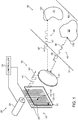
- Fig. 1 schematically shows a GT-TOF camera 20 operating to determine distances to features in a scene 30 having objects 31 and 32, in accordance with an embodiment of the disclosure.
- GT-TOF camera 20 which is shown very schematically, comprises an optical system represented by a lens 21, and a photosensor 22 having pixels 23 on which the lens system images scene 30.
- GT-TOF camera 20 optionally comprises a shutter 25 for shuttering or gating the camera ON and OFF, a light source 26, and a controller 24 that controls shutter 25 and light source 26.
- a GT-TOF camera may comprise a photosensor that includes circuitry operable to gate ON and gate OFF the photosensor and thereby the camera.
- a reference to shuttering or gating ON, or shuttering or gating OFF a GT-TOF camera is understood to include shuttering or gating the camera, or a pixel or pixels in the camera photosensor, ON and OFF using any methods or devices known in the art, irrespective of whether or not specific reference is made to a "separate" shutter.
- controller 24 controls GT-TOF camera 20 to transmit at least one pulse train of light pulses to illuminate the scene and gate ON and gate OFF photosensor 22 following each of a plurality of light pulses in each of the at least one light pulse train, in accordance with a gating configuration that conforms with an embodiment of the disclosure.
- the at least one pulse train comprises a plurality of light pulse trains
- controller 24 is assumed to control light source 26 to transmit a plurality of optionally four light pulse trains to illuminate scene 30 and determine distances to features in the scene.
- controller 24 controls shutter 25 to gate ON photosensor 22 for a gate associated with the given pulse train.
- pixels 23 in photosensor 22 register light reflected from the transmitted light pulse by features in scene 30 that are respectively imaged on the pixels and incident on photosensor 22 during the gate.
- An amount of light registered by a pixel 23 on which a feature of scene 30 is imaged is proportional to a correlation in time of the reflected light pulse and the gate.
- the correlation in time is a function of a round trip time, tR, for light to travel from GT-TOF camera 20 to the feature and back to the camera.
- a pixel in a camera photosensor registers an amount of incident light by accumulating positive or negative electric charge, also referred to as "photocharge", provided by electron-hole pairs generated by photons in the incident light.
- Circuitry in the TOF camera converts photocharge accumulated by the pixels into voltages that are used as measures of the amounts of photocharge they respectively accumulate.
- a set of voltages representing the accumulated photocharges and corresponding amounts of light registered by the pixels may be referred to as a "frame" of the photosensor. Acquiring a frame of a photosensor may be referred to as “reading" the photosensor, reading the pixels, or reading the photocharge in the pixels.
- An amount of light that a pixel registers may refer to an amount of optical energy incident on the pixel, an amount of photocharge accumulated by a pixel responsive to incident light, or to any representation of the accumulated photocharge, such as by way of example a voltage, current, or digital data generated responsive to the accumulated photocharge.
- GT-TOF camera 20 is schematically shown transmitting a pulse train 40 of the plurality of transmitted pulse trains that GT-TOF camera 20 transmits to illuminate scene 30.
- Pulse train 40 comprises transmitted light pulses 41, schematically represented by rectangular pulses associated with an overhead arrow 42 indicating direction of propagation of the light pulses.
- light pulses 41 are generally not rectangular, may have irregular pulse shapes, and may for example have rising and falling edges that resemble curves that describe a capacitor charging and discharging respectively.
- Light pulses 41 optionally have pulse widths between about 1 and 20 ns (nanoseconds).
- FIG. 1 objects 31 and 32 have features 131 and 132 respectively that are schematically shown reflecting light from transmitted light pulses 41 as trains 45 and 46 of reflected light pulses 47 and 48 respectively.
- Overhead arrows 67 and 68 schematically indicate direction of propagation of light pulses 47 and 48, respectively.
- Each reflected light pulse, 47 and 48 has reduced intensity compared to the transmitted light pulse 41 from which it was reflected but substantially a same pulse shape as the transmitted light pulse.
- Light in reflected light pulses 48 from feature 132 is imaged on a pixel 23-132. If the light in a reflected light pulse 48 reaches pixel 23-132 during the gate that follows the transmitted light pulse from which light in the reflected light pulse is reflected by feature 23, the pixel registers the light. An amount of the light that pixel 23-132 registers is proportional to a time correlation of reflected light pulse 48 and the gate, which as noted above is a function of a round trip time tR of light from light source 26 to feature 23 and back to camera 20. If all the light in reflected light pulse 48 reaches GT-TOF camera 20 before or after the gate, pixel 23-132 does not register light from the reflected light pulse.
- pixel 23-131 light from feature 131, which is schematically shown farther from GT-TOF camera 20 than feature 132, is imaged on a pixel 23-131.
- An amount of light from a reflected light pulse 47 reflected by feature 131 that is registered by pixel 23-131 is proportional to a time correlation of the reflected light pulse with the gate following the transmitted light pulse 41 from which light in the reflected light pulse is reflected by feature 131.
- Pixel 23-131 does not register light from reflected light pulse 47 if the light reaches the camera before or after the gate.
- the feature is located at a distance from GT-TOF camera 20 that is outside a maximum depth range, "DR-M", of the camera.
- DR-M maximum depth range
- the camera does not provide time of flight information useable to determine a distance from the camera at which the feature may be located, except possibly to provide information that the feature is out of range of the camera.
- Lower and upper bound distances that delimit the maximum depth range DR-M of GT-TOF camera 20 are schematically indicated by dashed lines 91 and 92.
- a gating configuration in accordance with an embodiment may provide an advantageous depth range for GT-TOF camera 20.
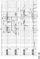
- GT-TOF camera 20 is assumed to be imaging scene 30 using a gating configuration 100 in accordance with an embodiment of the disclosure schematically illustrated in Fig. 2A .
- Gating configuration 100 optionally comprises a plurality of four light pulse trains, including light pulse train 40 shown in Fig. 1 , and three pulse trains referred to as pulse trains 50, 60, and 70 (not shown in Fig. 1 ), two multi-exposure gates which are optionally binary-exposure gates, and two single-exposure gates.
- FIG. 2A and figures that follow along times lines 40*, 50*, 60* and 70*, associated with pulse trains 40, 50, 60, and 70 respectively.
- Gates associated with each light pulse train 40, 50, 60, and 70 are shown along time lines 40*, 50*, 60* and 70* respectively, relative to transmission times represented by a nominal time to at which a light pulse in each of the light pulse trains is transmitted by light source 26.
- a shaded rectangle 41 represents a single, representative transmitted light pulse in light pulse train 40 transmitted by light source 26 at a transmission time of the pulse represented by to. Transmitted light pulse 41 is therefore shown with its leading edge located at time to.
- shaded rectangles 51, 61, and 71 represent, single, representative transmitted light pulses in light pulse trains 50, 60 and 70. Representative light pulses 51, 61, and 71 are transmitted at times represented by to and have their respective leading edges located at to.
- Transmitted light pulses 41, 51, 61, or 71 optionally have a same pulse width ⁇ p.
- An exposure period of a gate associated with transmitted light pulses in light pulses trains 40, 50, 60, and 70, such as transmitted light pulses 41, 51, 61, and 71, is schematically represented by a rectangle along time line, 40*, 50*, 60* and 70* respectively associated with the pulse train.
- the exposure periods of gates comprised in gating configuration 100 optionally have a substantially same duration, substantially equal to pulse width ⁇ p.
- Pulse train 40 is optionally associated with a binary-exposure gate G40 comprising exposure periods G40ea and G40eb separated by a hiatus H40 optionally having a duration substantially equal to duration ⁇ p of exposure periods G40ea and G40eb.
- Pulse train 50 is optionally associated with a single-exposure gate G50.
- Pulse train 60 is associated with a binary-exposure gate G60 comprising exposure periods G60ea and G60eb separated by a hiatus H60, optionally having a duration substantially equal to duration ⁇ p of exposure periods G60ea and G60eb.
- pulse train 70 is optionally associated with a single-exposure gate G70.
- ON times at which GT-TOF camera 20 is gated ON following a transmitted light pulse in a given pulse train 40, 50, 60 or 70 for exposure periods of the gates associated with the given pulse train may be different than ON times for a pulse train 40, 50, 60, or 70 different from the given pulse train.
- an ON time of an exposure period associated with light pulse 41 in pulse train 40, relative to a transmission time to of the light pulse is different than an ON time of an exposure period associated with light pulse 51 transmitted in pulse train 50, relative to the transmission time to of light pulse 51.
- Each ON time of an exposure period shown in Fig. 2A is labeled by a subscripted time, tj. Larger values for the subscript "j" indicate later ON times for an exposure period relative to a transmission time of a light pulse with which the exposure period is associated.
- any two "sequential" ON times tj are separated by a same relative time delay ⁇ rd.
- delay time ⁇ rd may be equal to one third of a time lapse between an ON time of a first exposure period of a multi-exposure gate and an ON time of an immediately subsequent exposure period of the multi-exposure period gate.
- ⁇ rd has a duration equal to (2/3) of a duration of the first exposure period.
- exposure period G40ea and hiatus H40 have a same duration equal to ⁇ p, and as a result ⁇ rd is optionally equal to (2/3) ⁇ p.
- An earliest ON time of gating configuration 100 is ON time t1 of exposure period G40ea of binary-exposure gate G40 that follows a transmission time to, of light pulse 41.
- a dotted line CF40 represents a time correlation function of binary-exposure gate G40 with a reflected light pulse, such as a reflected light pulse 47 or 48 shown in Fig. 1 , reflected from transmitted light pulse 41 by a feature in scene 30.
- Correlation function CF40 is shown as a function of a time at which a trailing edge of the reflected light pulse reaches GT-TOF camera 20.
- Correlation function CF40 has maxima when the leading edge of a reflected light pulse from scene 30 is at time t 1 or t 4 , for which times the reflected light pulse is coextensive with exposure period G40e a or G40e b respectively.
- Time (t 1 - ⁇ p ) therefore is equal to a smallest round trip time t R for which GT-TOF camera 20 registers light from a feature in scene 30.
- Distance (t 1 - ⁇ p )c/2 is therefore substantially equal to a nearest location to GT-TOF camera 20 of a feature in scene 30 for which the camera can provide time of flight distance information for the feature.
- Time (t 1 - ⁇ p ) therefore defines a lower bound distance "D LM " of a maximum depth range DR-M of GT-TOF camera 20 operating under gating configuration 100, and is indicated in Fig. 2A and figures that follow as a time t LM .
- t UM correlation function
- CF60 equals zero.
- Dotted lines CF50, CF60, and CF70 similarly represent correlation functions of gates G50, G60, and G70 respectively with light pulses reflected from transmitted light pulses 51, 61, and 71.
- Fig. 2B schematically illustrates timing relative to gates G40, G50, G60 and G70 of light pulses reflected from transmitted light pulses 41, 51, 61, and 71 by features in scene 30 that are located at lower and upper bound distances D LM and D UM of the depth range DR-M of GT-TOF camera 20.
- Reflected light pulses reflected from transmitted light pulses 41, 51, 61, and 71 by a feature located at a lower bound distance D LM from GT-TOF camera 20 are represented by shaded rectangles 41RL, 51RL, 61RL, and 71RL respectively along time lines 40*, 50*, 60*, and 70*.
- Leading and trailing edges of reflected light pulses 41RL, 51RL, 61RL, and 71RL are indicated by dashed lines associated with the pulses and respectively labeled “LE RL “ and "TE RL ".
- Reflected light pulses reflected from transmitted light pulses 41, 51, 61, and 71 by a feature at upper bound distance D UM are represented by shaded rectangles 41RU, 51RU, 61RU, and 71RU respectively along time lines 40*, 50*, 60*, and 70*.
- Leading and trailing edges of light pulses 41RU, 51RU, 61RU, and 71RU are indicated by dashed lines respectively labeled "LE RU “ and "TE RU ".
- Leading and trailing edges of light pulses 41RU, 51RU, 61RU, and 71RU are similarly indicated by dashed lines respectively labeled LE RU and TE RU .
- t U (t 6 + ⁇ p ) just as the camera is gated OFF at the end of exposure period G60e b of binary gate G60.
- GT-TOF camera 20 does not register any light from the feature that reflected the reflected light pulses and GT-TOF camera 20 cannot provide a distance to the feature.
- the feature and features at distances from GT-TOF camera 20 greater than D UM are out of range.
- a depth range of a GT-TOF camera may conventionally be extended by operating the camera to image a scene with transmitted light pulses from N transmitted light pulse trains. Following a transmission time of each transmitted light pulse in a given pulse train of the N pulse trains, the GT-TOF camera is gated ON for a single-exposure gate. The ON times, relative to pulse transmission times, of exposure periods associated with light pulses in different pulse trains are different and may be delayed relative to each other by a time interval ⁇ rd .
- GT-TOF camera 20 For a same set of a plurality of four light pulse trains used to illuminate a scene to provide a range image of the scene, GT-TOF camera 20 provides a maximum range depth that is 4/3 greater than a maximum range depth provided by a conventionally operating GT-TOF camera.
- a pixel 23 in the camera on which the feature is imaged accumulates photocharge for each light pulse train 40, 50, 60 and 70 responsive to light reflected by the feature from transmitted light pulses 41, 51, 61, and 71 that is incident on the camera during gates G40, G50, G60, and G70 respectively.
- the accumulated photocharges provide measures of amounts of light incident on the pixel from transmitted light pulses 41, 51, 61, and 71, which GT-TOF camera 20 may process in accordance with an embodiment of the disclosure to determine a distance of the feature from the camera.
- Fig. 2C graphically, schematically illustrates amounts of photocharge accumulated by pixel 23-132 (also shown in Fig. 1 ) on which feature 132 in scene 30 is imaged by GT-TOF camera 20 responsive to light reflected by the feature from transmitted light pulses 41, 51, 61, and 71, that is incident on GT-TOF camera 20.
- the incident light reaches GT-TOF camera 20 as reflected light pulses represented by shaded rectangles 48 (see also Fig. 1 ), 58, 68, and 78 respectively.
- Fig. 2C also graphically, schematically illustrates photocharge accumulated by pixel 23-131 ( Fig.
- GT-TOF camera 20 on which feature 131 in scene 30 is imaged by GT-TOF camera 20 responsive to light reflected by the feature from transmitted light pulse 41, 51, 61, and 71.
- the incident reflected light from feature 131 reaches GT-TOF camera 20 as reflected light pulses represented by shaded rectangles 47 (see also Fig. 1 ), 57, 67, and 77 respectively.
- Reflected light pulses 48, 58, 68, and 78 have leading and trailing edges indicated by dashed lines labeled LE132 and TE132 respectively.
- Light in the reflected light pulses reaches GT-TOF camera 20 after a round trip time t R (132) indicated for light at leading edges LE132 of reflected light pulses 48, 58, 68, and 78 along time line 70*.
- An amount of photocharge that pixel 23-132 accumulates responsive to light in a reflected light pulse 48, 58, 68, and 78 is graphically represented by an amount by which the reflected light pulse overlaps a gate G40, G50, G60 and G70 respectively.
- Intersections of trailing edge dashed line TE132 with correlation functions CF40, CF50, CF60, and CF70 associated with gates G40, G50, G60, and G70 also represent amounts of the photocharge accumulated by pixel 23-132 responsive to reflected light pulses 48, 58, 68, and 78.
- Fig. 2C shows that for the distance from GT-TOF camera 20 at which feature 132 is located, light in reflected light pulses 48, 58, and 68 is registered by pixel 23-132 during exposure period G40e a of binary gate G40, during gate G50, and during exposure period G60e a of binary gate G60.
- pixel 23-132 does not register light from reflected light pulse 78 because light in reflected light pulse 78 reaches GT-TOF camera 20 before the camera is gated ON for gate G70.
- Q 40 (132), Q 50 (132), and Q 60 (132) label intersections of trailing edge dashed line TE132 with correlation functions CF40, CF50, CF60. It is noted that an amount of photocharge Q 40 (132) accumulated by pixel 23-132 during binary-exposure gate G40 does not provide any information as to whether the photocharge was accumulated responsive to light incident on pixel 23-132 during exposure period G40e a or exposure period G40e b of the binary-exposure gate.
- Q o is an amount of photocharge accumulated by pixel 23-132 if a light pulse reflected from feature 132 is coincident with an exposure period of the gate and completely overlaps the gate.
- Q o also referred to as a normalization photocharge, may generally be determined from photocharge accumulated during exposure periods of different gates or may be removed from equations for t R (132) by manipulation of the equations.
- the expression following the second equals sign in equation (7) may be manipulated to provide an expression for Q o in terms of t R (132), t 3 and Q 60 (132) and the expression for Q o substituted into the expression for t R (132) following the first equals sign.
- reflected light pulses 47, 57, 67, and 77 from feature 131 are represented in Fig. 2C by shaded rectangles having leading and trailing edges indicated by dashed lines labeled LE131 and TE131 respectively.
- Light in the reflected light pulses reaches GT-TOF camera 20 after a round trip time t R (131) indicated for light at leading edge dashed line LE131 along time line 70*.
- pixel 23-131 For a distance d(131) from GT-TOF camera 20 at which feature 131 is assumed to be located, pixel 23-131 accumulates photocharge Q 40 (131), Q 60 (131), and Q 70 (131) during gates G40, G60, and G70 but does not accumulate photocharge responsive to light from feature 131 during gate G(50). Whereas feature 131 is farther from GT-TOF camera 20 than feature 132 ( Fig. 1 ), for assumed distance d(131) the amounts of accumulated photocharge Q 40 (131) and Q 60 (131) are substantially equal to photocharge Q 40 (132) and Q 60 (132) accumulated for feature 132.
- photocharge responsive to reflected light from feature 131 is accumulated during gate G70 but not during gate G50 indicating that photocharge Q 40 (131) and Q 60 (131) is accumulated during exposure periods G40 eb and G60 eb and not during exposure periods G40 ea and G60 ea .
- Expressions (7) and (8) enable calculation of round trip times t R (132) and t R (131) for features 132 and 131, assuming transmitted light pulses 41-71 and gates G40-G70, because the expressions provide a set of two simultaneous equations in two unknowns.
- the two equations are generated from measurements of photocharge for at least two gates. In the case of expression (7) the measurements are photocharges Q 40 and Q 60 acquired for gates G40 and G60.
- Photocharge measurements for a feature in scene 30 for at least two gates are acquired by GT-TOF camera 20 for a depth range, DR2, of GT-TOF camera 20 that is smaller than the depth range DR-M shown in Fig. 2B .
- depth range DR-M extends between distances for which trailing edges, of reflected light pulses from features in scene 30, for example trailing edges TE132 or TE131 ( Fig. 2C ) of reflected light pulses from features 132 and 131 lie between times t 1 and t 9 .
- Measurements of photocharge for three gates generally provide sufficient information useable to remove or moderate effects of background light on determinations of round trip times and corresponding distances. For example, for feature 132 at a distance from GT-TOF camera 20 shown in Fig. 2C the camera accumulates total amounts of photocharge Q T40 (132), Q T50 (132), and Q T60 (132) during gates G40, G50, and G60.
- GT-TOF camera 20 acquires photocharge measurements for three gates of gating configuration 100 for features in scene 30 for a depth range DR3 schematically indicated in Fig. 2E by a block arrow labeled DR3, which is smaller than depth range DR2 ( Fig. 2D ).
- Depth range DR3 extends for distances for which trialing edges of reflected light pulses from features in scene 30 arrive at GT-TOF camera 20 between times t 3 and t 7 , and corresponding round trip times t R lie between times t L3 and t U3 .
- Reflected light pulses 41RL, 51RL, 61RL, and 71RL from features in scene 30 located at a lower bound distance of range DR3 having trailing edges TE RL at time t 3 and reflected light pulses 41UL, 51UL, 61UL and 71UL for features in scene 30 located at an upper bound distance of range DR3 having trailing edges TE RU at time t 7 are shown in a Fig. 2E .
- Round trip times t L2 and t U2 that correspond to times t 3 and t 7 and define upper and lower distance bounds for range DR2 are also shown in Fig. 2E .
- a table below gives expressions for round trip time t R for a feature in scene 30 as a function of photocharges Q 40 , Q 50 , Q 60 , and/or Q 70 , that may be accumulated by a pixel 23 imaging the feature responsive to reflected light from the feature.
- a first column in the table lists photocharge Q 40 , Q 50 , Q 60 , and/or Q 70 accumulated by GT-TOF camera 20 during gates G40, G50, G60, and G70 responsive to light reflected by the feature from light pulse trains 40, 50, 60, and 70 that the camera transmits to illuminate the scene. If a photocharge is not listed in a cell in the first column it is not accumulated for a distance at which the feature is located from GT-TOF camera 20.
- a second column provides the distance range DR-M, DR2, or DR3 for a distance at which a feature for which the photocharges listed in the first column are accumulated is located.
- a third column headed "AND" lists a relationship between accumulated photocharges listed in the first column. For the photocharge noted as accumulated in the first column and the condition entered in the second column, a cell in the third column lists a time interval during which a trailing edge of a light pulse reflected by the feature reaches GT-TOF camera 20.
- a last column provides a formula or formulae that may be used to determine the round trip time for the feature responsive to the photocharge listed in the first column. For convenience of presentation the formulae in the last column assume that Q B is zero.
- correlation functions CF40, CF50, CF60, and CF70 are rectilinear triangular functions.
- Correlation functions CF40, CF50, CF60, and CF70 are rectilinear and triangular because they represent correlation functions assuming that gates G40,...G70, transmitted light pulses 41, ..., 71, and light pulses reflected from the transmitted light pulses have a same duration and may be represented by idealized, rectangular functions.
- Idealized rectangular representations of light pulses and gates, and rectilinear triangular correlation functions CF40, CF50, CF60, and CF70 are useful in visually representing and understanding features of a gating configuration in accordance with an embodiment of the disclosure.
- light pulses, gates, and correlation functions may usefully be approximated by idealized shapes, in practice, light pulses, gates, and correlation functions of a gating configuration, in accordance with an embodiment of the disclosure, assume more complex and irregular shapes.
- a GT-TOF camera in accordance with an embodiment of the disclosure, such as GT-TOF camera 20, may therefore advantageously use formulae or an algorithm for processing photocharges accumulated by the camera that are different from or not implied by those shown in the table.
- the formulae may be modified or algorithm configured to account for the more complex and irregular shapes that may characterize transmitted light pulses and gates that the GT-TOF camera might use.
- ACCUMULATED PHOTOCHARGE RANGE AND THEN AND t R EQUALS NONE t TE ⁇ t 1 OUT OF RANGE
- gating configuration 100 comprises two binary gates G40 and G60 and two single single-exposure gates
- G50 and G70 a gating configuration in accordance with an embodiment of the disclosure is not limited to two multi-exposure gates that are binary.
- Fig. 3 shows a schematic timeline graph illustrating a gating configuration 200 comprising three optionally binary gates G40, G50, G60 and a single exposure gate G70.
- Fig. 3 is similar to Fig. 2B and shows reflected light pulses 41RL...71RL from a feature at a lower bound distance D LM of a maximum depth range provided by gating configuration 200 and reflected light pulses 41RU...71RU from a feature at an upper bound distance D UM of the depth range.
- Figs 2A-2E and Fig. 3 schematically show gating configurations in accordance with embodiments of the disclosure for which width of transmitted light pulses are equal to widths of gate exposure periods.
- practice of an embodiment of the disclosure is not limited to gating configurations having light pulse widths equal to the widths of gate exposure periods.
- a GT-TOF camera in accordance with an embodiment of the invention may operate using a gating configuration for which pulse widths are smaller than duration of gate exposure periods.
- a gating configuration may have gate exposure periods as much as 125% longer than pulse widths of the transmitted light pulses. The longer gate exposure periods may be advantageous for improving resolution and/or precision of feature distances that a GT-TOF camera in accordance with an embodiment of the disclosure provides.
- a photosensor may comprise CMOS smart pixels having a plurality of different storage regions for photocharge.
- the pixels may be controllable to accumulate photocharge generated by light incident on the pixels during different gates in different storage regions of the plurality of storage regions.
- a GT-TOF camera comprising such a photosensor may be controlled to accumulate photocharge for different gates, for example gates G40, G50, G60 and G70, from reflected light pulses reflected from light pulses transmitted in a same single train of light pulses.
- a multi-exposure gate may be implemented by a plurality of exposure periods each following a different transmitted light pulse.
- a pixel may be controlled to register light during a first exposure period having a first ON time following transmission of a first light pulse and subsequently during a second exposure period having a second ON time following a different, second light pulse, wherein the second ON time is substantially equal to the first ON time plus a sum of a width of the first exposure period and a hiatus.
- an amount of light registered by the pixel will be substantially equal to an amount of light the pixels would have registered for a multi-exposure gate following a same transmitted light pulse and comprising the first and second exposure periods having the first and second ON times respectively.
- each of the verbs, "comprise” “include” and “have”, and conjugates thereof, are used to indicate that the object or objects of the verb are not necessarily a complete listing of components, elements or parts of the subject or subjects of the verb.
Landscapes
- Physics & Mathematics (AREA)
- Engineering & Computer Science (AREA)
- General Physics & Mathematics (AREA)
- Remote Sensing (AREA)
- Computer Networks & Wireless Communication (AREA)
- Radar, Positioning & Navigation (AREA)
- Electromagnetism (AREA)
- Multimedia (AREA)
- Signal Processing (AREA)
- Optical Radar Systems And Details Thereof (AREA)
- Measurement Of Optical Distance (AREA)
- Length Measuring Devices By Optical Means (AREA)
- Studio Devices (AREA)
Claims (15)
- Caméra de temps de vol à déclenchement périodique (20) permettant de déterminer des distances à des éléments dans une scène, la caméra de temps de vol à déclenchement périodique comprenant :une source de lumière (26) configurée pour transmettre au moins un train (40, 50, 60, 70) d'impulsions lumineuses pour éclairer la scène ;un photodétecteur (22) comprenant des pixels (23) configuré pour enregistrer des quantités de lumière réfléchie à partir d'impulsions lumineuses transmises (41, 51, 61, 71) dans l'au moins un train d'impulsions lumineuses par des éléments dans la scène imagée sur les pixels ;un dispositif de commande (24) configuré pour commander la source de lumière pour transmettre l'au moins un train de trains d'impulsions lumineuses pour éclairer la scène, le dispositif de commande étant en outre configuré pour déclencher et éteindre le photodétecteur, de sorte que le photodétecteur soit déclenché suite à chacune d'une première pluralité d'impulsions lumineuses transmises dans l'au moins un train d'impulsions lumineuses pour une première grille à expositions multiples ayant une pluralité de périodes d'exposition pour enregistrer des premières quantités de lumière réfléchie par des éléments dans la scène à partir de la première pluralité d'impulsions lumineuses, des périodes d'exposition consécutives étant séparées par une pause pendant laquelle le photodétecteur est éteint ;caractérisée en ce que le dispositif de commande est en outre configuré pour déclencher le photodétecteur suite à chacune d'une deuxième pluralité d'impulsions lumineuses transmises dans l'au moins un train d'impulsions lumineuses pour une première grille à exposition unique ayant une période d'exposition unique pour enregistrer des deuxièmes quantités de lumière réfléchie par des éléments dans la scène à partir de la deuxième pluralité d'impulsions lumineuses.
- Caméra de temps de vol à déclenchement périodique selon la revendication 1, dans laquelle le dispositif de commande (24) détermine une distance à un élément dans la scène sur la base de premières et deuxièmes quantités de lumière réfléchie qu'un pixel (23) enregistre pour l'élément et pendant laquelle période d'exposition de la première grille à expositions multiples le pixel a enregistré la première quantité de lumière sur la base des premières et deuxièmes quantités de lumière réfléchie enregistrées par le pixel pour l'élément.
- Caméra de temps de vol à déclenchement périodique selon l'une quelconque des revendications précédentes, dans laquelle la grille à expositions multiples comprend trois périodes d'exposition ou plus.
- Caméra de temps de vol à déclenchement périodique selon la revendication 1 ou la revendication 2, dans laquelle le dispositif de commande (24) déclenche le photodétecteur (22) pour une seconde grille à expositions multiples suite à chacune d'une troisième pluralité d'impulsions lumineuses transmises dans l'au moins un train d'impulsions lumineuses (40) pour enregistrer des troisièmes quantités de lumière réfléchie à partir de la troisième pluralité d'impulsions lumineuses par des éléments dans la scène.
- Caméra de temps de vol à déclenchement périodique selon la revendication 4, dans laquelle au moins l'une des première et seconde grilles à expositions multiples comprend trois périodes d'exposition ou plus.
- Caméra de temps de vol à déclenchement périodique selon la revendication 4 ou la revendication 5, dans laquelle le dispositif de commande (24) déclenche le photodétecteur pour une seconde grille à exposition unique suite à chacune d'une quatrième pluralité d'impulsions lumineuses transmises dans l'au moins un train d'impulsions lumineuses (40) pour enregistrer des quatrièmes quantités de lumière réfléchie à partir de la quatrième pluralité d'impulsions lumineuses par des éléments dans la scène.
- Caméra de temps de vol à déclenchement périodique selon la revendication 6, dans laquelle le dispositif de commande (24) détermine une distance à un élément dans la scène sur la base d'au moins l'une des premières et troisièmes quantités de lumière réfléchie qu'un pixel (23) enregistre pour l'élément et pendant laquelle des périodes d'exposition de l'au moins une grille à expositions multiples le pixel a enregistré l'au moins une des premières et troisièmes quantités de lumière réfléchie pour l'élément.
- Caméra de temps de vol à déclenchement périodique selon la revendication 7, dans laquelle le dispositif de commande (24) détermine pendant laquelle des périodes d'exposition des première et seconde grilles à expositions multiples une lumière réfléchie a été enregistrée par le pixel (23) sur la base d'au moins l'une des premières, deuxièmes, troisièmes, et quatrièmes quantités de lumière que le pixel enregistre pour le pixel.
- Caméra de temps de vol à déclenchement périodique selon l'une quelconque des revendications 6 à 8, dans laquelle chacune des périodes d'exposition des première et seconde grilles à expositions multiples ont une durée sensiblement identique.
- Caméra de temps de vol à déclenchement périodique selon la revendication 9, dans laquelle les périodes d'exposition des première et seconde grilles à exposition unique ont une durée sensiblement égale à la durée de chacune des périodes d'exposition des grilles à expositions multiples.
- Caméra de temps de vol à déclenchement périodique selon l'une quelconque des revendications 6 à 10, dans laquelle par rapport à des temps de transmission des impulsions lumineuses (41) qu'ils suivent respectivement, les temps de déclenchement de périodes d'exposition différentes sont différents, et des temps de déclenchement différents qui sont temporellement adjacents diffèrent d'un même intervalle de temps.
- Caméra de temps de vol à déclenchement périodique selon la revendication 11, dans laquelle l'intervalle de temps est sensiblement égal à un tiers d'une durée égale à une somme d'une durée d'une période d'exposition plus une durée d'une pause séparant deux périodes d'exposition consécutives de la première grille à expositions multiples.
- Caméra de temps de vol à déclenchement périodique selon la revendication 12, dans laquelle la durée de la période d'exposition et la pause sont sensiblement égales.
- Caméra de temps de vol à déclenchement périodique selon la revendication 12 ou la revendication 13, dans laquelle chacune des périodes d'exposition des grilles à exposition unique et des grilles à expositions multiples a sensiblement une durée identique.
- Procédé de détermination de distances à des éléments dans une scène en utilisant une caméra de temps de vol à déclenchement périodique (20), le procédé comprenant :la transmission d'au moins un train (40, 50, 60, 70) d'impulsions lumineuses pour éclairer la scène ;suite à chaque impulsion (41, 51, 61, 71) d'une première pluralité d'impulsions lumineuses transmises dans l'au moins un train d'impulsions lumineuses, l'enregistrement de premières quantités de lumière réfléchie par les éléments dans la scène à partir de la première pluralité d'impulsions lumineuses pendant une période d'exposition d'une première grille à expositions multiples ayant une pluralité de périodes d'exposition pendant lesquelles un photodétecteur (22) est déclenché, des périodes d'exposition consécutives étant séparées par une pause pendant laquelle le photodétecteur (22) est éteint ;l'utilisation des premières quantités de lumière enregistrée pour déterminer les distances aux éléments ;caractérisé par, suite à chaque impulsion lumineuse d'une deuxième pluralité d'impulsions lumineuses transmises dans l'au moins un train d'impulsions lumineuses, l'enregistrement de deuxièmes quantités de lumière réfléchie par les éléments à partir de la deuxième pluralité d'impulsions lumineuses pendant une grille à exposition unique ayant une période d'exposition unique pendant laquelle le photodétecteur (22) est déclenché,et l'utilisation en outre des deuxièmes quantités de lumière enregistrée pour déterminer les distances aux éléments.
Applications Claiming Priority (2)
| Application Number | Priority Date | Filing Date | Title |
|---|---|---|---|
| US14/609,475 US9874630B2 (en) | 2015-01-30 | 2015-01-30 | Extended range gated time of flight camera |
| PCT/US2016/013503 WO2016122903A1 (fr) | 2015-01-30 | 2016-01-15 | Caméra à temps de vol à fenêtre de distance étendue |
Publications (2)
| Publication Number | Publication Date |
|---|---|
| EP3250944A1 EP3250944A1 (fr) | 2017-12-06 |
| EP3250944B1 true EP3250944B1 (fr) | 2019-03-06 |
Family
ID=55358115
Family Applications (1)
| Application Number | Title | Priority Date | Filing Date |
|---|---|---|---|
| EP16704505.3A Active EP3250944B1 (fr) | 2015-01-30 | 2016-01-15 | Caméra de temps de vol à déclenchement périodique |
Country Status (4)
| Country | Link |
|---|---|
| US (1) | US9874630B2 (fr) |
| EP (1) | EP3250944B1 (fr) |
| CN (1) | CN107209254B (fr) |
| WO (1) | WO2016122903A1 (fr) |
Cited By (1)
| Publication number | Priority date | Publication date | Assignee | Title |
|---|---|---|---|---|
| WO2020070280A3 (fr) * | 2018-10-04 | 2020-05-14 | Ams Ag | Mesures de temps de vol à haute résolution |
Families Citing this family (12)
| Publication number | Priority date | Publication date | Assignee | Title |
|---|---|---|---|---|
| US9971023B2 (en) * | 2015-05-04 | 2018-05-15 | Infineon Technologies Ag | Systems and methods for time of flight measurement using a single exposure |
| US9864048B2 (en) * | 2015-05-17 | 2018-01-09 | Microsoft Technology Licensing, Llc. | Gated time of flight camera |
| US9945936B2 (en) * | 2015-05-27 | 2018-04-17 | Microsoft Technology Licensing, Llc | Reduction in camera to camera interference in depth measurements using spread spectrum |
| US11280908B2 (en) * | 2017-08-15 | 2022-03-22 | Black Sesame Technologies Inc. | Obstacle detection by global shutter image sensor |
| US20190072771A1 (en) * | 2017-09-05 | 2019-03-07 | Facebook Technologies, Llc | Depth measurement using multiple pulsed structured light projectors |
| US10962790B2 (en) * | 2017-09-05 | 2021-03-30 | Facebook Technologies, Llc | Depth measurement using a pulsed structured light projector |
| US12498463B2 (en) | 2018-09-06 | 2025-12-16 | Sony Semiconductor Solutions Corporation | Time of flight apparatus and method |
| US11237256B2 (en) | 2018-09-19 | 2022-02-01 | Waymo Llc | Methods and systems for dithering active sensor pulse emissions |
| WO2020058264A1 (fr) | 2018-09-19 | 2020-03-26 | Sony Semiconductor Solutions Corporation | Appareil et procédé de temps de vol |
| US11259002B2 (en) * | 2019-02-15 | 2022-02-22 | Analog Devices International Unlimited Company | Time-of-flight camera and proximity detector |
| EP3798673A1 (fr) * | 2019-09-25 | 2021-03-31 | Xenomatix NV | Procédé et dispositif pour déterminer les distances jusqu'à une scène |
| CN113126105B (zh) * | 2019-12-30 | 2025-07-15 | 睿镞科技(北京)有限责任公司 | 三维测距方法和装置 |
Family Cites Families (16)
| Publication number | Priority date | Publication date | Assignee | Title |
|---|---|---|---|---|
| US4963017A (en) | 1989-05-01 | 1990-10-16 | General Electric Company | Variable depth range camera |
| DE50307744D1 (de) | 2003-10-29 | 2007-08-30 | Fraunhofer Ges Forschung | Abstandssensor und verfahren zur abstandserfassung |
| US7379100B2 (en) | 2004-02-12 | 2008-05-27 | Canesta, Inc. | Method and system to increase dynamic range of time-of-flight (TOF) and/or imaging sensors |
| CN102099703A (zh) * | 2007-12-19 | 2011-06-15 | 微软国际控股私有有限公司 | 3d照相机及其选通方法 |
| US8724921B2 (en) | 2008-05-05 | 2014-05-13 | Aptina Imaging Corporation | Method of capturing high dynamic range images with objects in the scene |
| CN102112844B (zh) * | 2008-07-29 | 2013-04-24 | 微软国际控股私有有限公司 | 成像系统 |
| US8717469B2 (en) * | 2010-02-03 | 2014-05-06 | Microsoft Corporation | Fast gating photosurface |
| US9194953B2 (en) * | 2010-10-21 | 2015-11-24 | Sony Corporation | 3D time-of-light camera and method |
| EP2477043A1 (fr) * | 2011-01-12 | 2012-07-18 | Sony Corporation | Caméra temps de vol 3D et procédé |
| US9137463B2 (en) | 2011-05-12 | 2015-09-15 | Microsoft Technology Licensing, Llc | Adaptive high dynamic range camera |
| GB2492848A (en) * | 2011-07-15 | 2013-01-16 | Softkinetic Sensors Nv | Optical distance measurement |
| EP2594959B1 (fr) | 2011-11-17 | 2017-01-04 | Heptagon Micro Optics Pte. Ltd. | Système et procédé pour le fonctionnement de caméra TOF multiple utilisant un saut de phase |
| JP6246131B2 (ja) | 2012-01-10 | 2017-12-13 | ソフトキネティック センサーズ エヌブイ | タイムオブフライト信号の処理における又はこれに関する改良 |
| US20130235160A1 (en) | 2012-03-06 | 2013-09-12 | Microsoft Corporation | Optical pulse shaping |
| US8879050B2 (en) | 2012-12-04 | 2014-11-04 | Texas Instruments Incorporated | Method for dynamically adjusting the operating parameters of a TOF camera according to vehicle speed |
| FR3005746B1 (fr) | 2013-05-14 | 2016-09-16 | Cie Ind Des Lasers - Cilas | Dispositif d'illumination laser a obturateur integre. |
-
2015
- 2015-01-30 US US14/609,475 patent/US9874630B2/en active Active
-
2016
- 2016-01-15 EP EP16704505.3A patent/EP3250944B1/fr active Active
- 2016-01-15 CN CN201680008134.5A patent/CN107209254B/zh active Active
- 2016-01-15 WO PCT/US2016/013503 patent/WO2016122903A1/fr not_active Ceased
Non-Patent Citations (1)
| Title |
|---|
| None * |
Cited By (2)
| Publication number | Priority date | Publication date | Assignee | Title |
|---|---|---|---|---|
| WO2020070280A3 (fr) * | 2018-10-04 | 2020-05-14 | Ams Ag | Mesures de temps de vol à haute résolution |
| US12320897B2 (en) | 2018-10-04 | 2025-06-03 | Ams Ag | High resolution time-of-flight measurements |
Also Published As
| Publication number | Publication date |
|---|---|
| CN107209254A (zh) | 2017-09-26 |
| US9874630B2 (en) | 2018-01-23 |
| EP3250944A1 (fr) | 2017-12-06 |
| US20160223656A1 (en) | 2016-08-04 |
| CN107209254B (zh) | 2020-08-04 |
| WO2016122903A1 (fr) | 2016-08-04 |
Similar Documents
| Publication | Publication Date | Title |
|---|---|---|
| EP3250944B1 (fr) | Caméra de temps de vol à déclenchement périodique | |
| EP3058389B1 (fr) | Imagerie probabiliste de temps de vol | |
| EP3990946B1 (fr) | Système de traitement pour mesures lidar | |
| Maccarone et al. | Three-dimensional imaging of stationary and moving targets in turbid underwater environments using a single-photon detector array | |
| Niclass et al. | A 0.18-$\mu $ m CMOS SoC for a 100-m-Range 10-Frame/s 200$\,\times\, $96-Pixel Time-of-Flight Depth Sensor | |
| KR102348933B1 (ko) | 거리 측정 장치 및 방법 | |
| CN108291961B (zh) | 固体摄像装置、距离测定装置及距离测定方法 | |
| US10681295B2 (en) | Time of flight camera with photon correlation successive approximation | |
| CN102113309B (zh) | 卷帘相机系统 | |
| US12140708B2 (en) | Configurable array of single-photon detectors | |
| US20120287242A1 (en) | Adaptive high dynamic range camera | |
| US20160334508A1 (en) | Gated time of flight camera | |
| US20200018853A1 (en) | Photodetector | |
| CN102147553A (zh) | 快速选通光敏面 | |
| KR102952247B1 (ko) | 다중 리턴 기능을 가진 픽셀을 구비한 가이거 모드 애벌랜치 포토다이어드 기반의 수신기를 포함하는 lidar 시스템 | |
| US20190187256A1 (en) | Non-spad pixels for direct time-of-flight range measurement | |
| US9071763B1 (en) | Uniform illumination image capture | |
| CN105338268B (zh) | 图像传感器及其去除太阳黑斑方法和去除太阳黑斑装置 | |
| KR102198941B1 (ko) | TOF(Time of Flight)를 이용한 거리 측정 장치 및 방법 | |
| EP3487164A1 (fr) | Détection d'image à accès aléatoire sans cadre | |
| Holder | Exploiting VERITAS timing information | |
| FR3013125A1 (fr) | Procede pour ameliorer la resolution en energie de detecteurs de rayons gamma a scintillation, systeme, composant et application associes | |
| Oguh et al. | Time-to-brightness converter (TBC): measuring photon arrival time with conventional cameras | |
| Ma et al. | An SPAD-Based dToF LiDAR Readout Circuit With Histogram-Free Method and Shared TDC Architecture | |
| US12432475B2 (en) | Digital pixel architecture supporting low power and high dynamic range operation having a counter that stops counting pulses in response to detecting a voltage on a capacitor exceeding a threshold |
Legal Events
| Date | Code | Title | Description |
|---|---|---|---|
| STAA | Information on the status of an ep patent application or granted ep patent |
Free format text: STATUS: THE INTERNATIONAL PUBLICATION HAS BEEN MADE |
|
| PUAI | Public reference made under article 153(3) epc to a published international application that has entered the european phase |
Free format text: ORIGINAL CODE: 0009012 |
|
| STAA | Information on the status of an ep patent application or granted ep patent |
Free format text: STATUS: REQUEST FOR EXAMINATION WAS MADE |
|
| 17P | Request for examination filed |
Effective date: 20170727 |
|
| AK | Designated contracting states |
Kind code of ref document: A1 Designated state(s): AL AT BE BG CH CY CZ DE DK EE ES FI FR GB GR HR HU IE IS IT LI LT LU LV MC MK MT NL NO PL PT RO RS SE SI SK SM TR |
|
| AX | Request for extension of the european patent |
Extension state: BA ME |
|
| DAV | Request for validation of the european patent (deleted) | ||
| DAX | Request for extension of the european patent (deleted) | ||
| GRAP | Despatch of communication of intention to grant a patent |
Free format text: ORIGINAL CODE: EPIDOSNIGR1 |
|
| STAA | Information on the status of an ep patent application or granted ep patent |
Free format text: STATUS: GRANT OF PATENT IS INTENDED |
|
| INTG | Intention to grant announced |
Effective date: 20181004 |
|
| RIN1 | Information on inventor provided before grant (corrected) |
Inventor name: GUDAITIS, ALGIRD Inventor name: HALL, MICHAEL |
|
| GRAS | Grant fee paid |
Free format text: ORIGINAL CODE: EPIDOSNIGR3 |
|
| GRAA | (expected) grant |
Free format text: ORIGINAL CODE: 0009210 |
|
| STAA | Information on the status of an ep patent application or granted ep patent |
Free format text: STATUS: THE PATENT HAS BEEN GRANTED |
|
| AK | Designated contracting states |
Kind code of ref document: B1 Designated state(s): AL AT BE BG CH CY CZ DE DK EE ES FI FR GB GR HR HU IE IS IT LI LT LU LV MC MK MT NL NO PL PT RO RS SE SI SK SM TR |
|
| REG | Reference to a national code |
Ref country code: GB Ref legal event code: FG4D |
|
| REG | Reference to a national code |
Ref country code: CH Ref legal event code: EP Ref country code: AT Ref legal event code: REF Ref document number: 1105294 Country of ref document: AT Kind code of ref document: T Effective date: 20190315 |
|
| REG | Reference to a national code |
Ref country code: DE Ref legal event code: R096 Ref document number: 602016010712 Country of ref document: DE |
|
| REG | Reference to a national code |
Ref country code: IE Ref legal event code: FG4D |
|
| REG | Reference to a national code |
Ref country code: NL Ref legal event code: FP |
|
| REG | Reference to a national code |
Ref country code: LT Ref legal event code: MG4D |
|
| PG25 | Lapsed in a contracting state [announced via postgrant information from national office to epo] |
Ref country code: LT Free format text: LAPSE BECAUSE OF FAILURE TO SUBMIT A TRANSLATION OF THE DESCRIPTION OR TO PAY THE FEE WITHIN THE PRESCRIBED TIME-LIMIT Effective date: 20190306 Ref country code: FI Free format text: LAPSE BECAUSE OF FAILURE TO SUBMIT A TRANSLATION OF THE DESCRIPTION OR TO PAY THE FEE WITHIN THE PRESCRIBED TIME-LIMIT Effective date: 20190306 Ref country code: NO Free format text: LAPSE BECAUSE OF FAILURE TO SUBMIT A TRANSLATION OF THE DESCRIPTION OR TO PAY THE FEE WITHIN THE PRESCRIBED TIME-LIMIT Effective date: 20190606 Ref country code: SE Free format text: LAPSE BECAUSE OF FAILURE TO SUBMIT A TRANSLATION OF THE DESCRIPTION OR TO PAY THE FEE WITHIN THE PRESCRIBED TIME-LIMIT Effective date: 20190306 |
|
| PG25 | Lapsed in a contracting state [announced via postgrant information from national office to epo] |
Ref country code: BG Free format text: LAPSE BECAUSE OF FAILURE TO SUBMIT A TRANSLATION OF THE DESCRIPTION OR TO PAY THE FEE WITHIN THE PRESCRIBED TIME-LIMIT Effective date: 20190606 Ref country code: GR Free format text: LAPSE BECAUSE OF FAILURE TO SUBMIT A TRANSLATION OF THE DESCRIPTION OR TO PAY THE FEE WITHIN THE PRESCRIBED TIME-LIMIT Effective date: 20190607 Ref country code: RS Free format text: LAPSE BECAUSE OF FAILURE TO SUBMIT A TRANSLATION OF THE DESCRIPTION OR TO PAY THE FEE WITHIN THE PRESCRIBED TIME-LIMIT Effective date: 20190306 Ref country code: LV Free format text: LAPSE BECAUSE OF FAILURE TO SUBMIT A TRANSLATION OF THE DESCRIPTION OR TO PAY THE FEE WITHIN THE PRESCRIBED TIME-LIMIT Effective date: 20190306 Ref country code: HR Free format text: LAPSE BECAUSE OF FAILURE TO SUBMIT A TRANSLATION OF THE DESCRIPTION OR TO PAY THE FEE WITHIN THE PRESCRIBED TIME-LIMIT Effective date: 20190306 |
|
| REG | Reference to a national code |
Ref country code: AT Ref legal event code: MK05 Ref document number: 1105294 Country of ref document: AT Kind code of ref document: T Effective date: 20190306 |
|
| PG25 | Lapsed in a contracting state [announced via postgrant information from national office to epo] |
Ref country code: CZ Free format text: LAPSE BECAUSE OF FAILURE TO SUBMIT A TRANSLATION OF THE DESCRIPTION OR TO PAY THE FEE WITHIN THE PRESCRIBED TIME-LIMIT Effective date: 20190306 Ref country code: IT Free format text: LAPSE BECAUSE OF FAILURE TO SUBMIT A TRANSLATION OF THE DESCRIPTION OR TO PAY THE FEE WITHIN THE PRESCRIBED TIME-LIMIT Effective date: 20190306 Ref country code: RO Free format text: LAPSE BECAUSE OF FAILURE TO SUBMIT A TRANSLATION OF THE DESCRIPTION OR TO PAY THE FEE WITHIN THE PRESCRIBED TIME-LIMIT Effective date: 20190306 Ref country code: AL Free format text: LAPSE BECAUSE OF FAILURE TO SUBMIT A TRANSLATION OF THE DESCRIPTION OR TO PAY THE FEE WITHIN THE PRESCRIBED TIME-LIMIT Effective date: 20190306 Ref country code: PT Free format text: LAPSE BECAUSE OF FAILURE TO SUBMIT A TRANSLATION OF THE DESCRIPTION OR TO PAY THE FEE WITHIN THE PRESCRIBED TIME-LIMIT Effective date: 20190706 Ref country code: SK Free format text: LAPSE BECAUSE OF FAILURE TO SUBMIT A TRANSLATION OF THE DESCRIPTION OR TO PAY THE FEE WITHIN THE PRESCRIBED TIME-LIMIT Effective date: 20190306 Ref country code: ES Free format text: LAPSE BECAUSE OF FAILURE TO SUBMIT A TRANSLATION OF THE DESCRIPTION OR TO PAY THE FEE WITHIN THE PRESCRIBED TIME-LIMIT Effective date: 20190306 Ref country code: EE Free format text: LAPSE BECAUSE OF FAILURE TO SUBMIT A TRANSLATION OF THE DESCRIPTION OR TO PAY THE FEE WITHIN THE PRESCRIBED TIME-LIMIT Effective date: 20190306 |
|
| PG25 | Lapsed in a contracting state [announced via postgrant information from national office to epo] |
Ref country code: SM Free format text: LAPSE BECAUSE OF FAILURE TO SUBMIT A TRANSLATION OF THE DESCRIPTION OR TO PAY THE FEE WITHIN THE PRESCRIBED TIME-LIMIT Effective date: 20190306 Ref country code: PL Free format text: LAPSE BECAUSE OF FAILURE TO SUBMIT A TRANSLATION OF THE DESCRIPTION OR TO PAY THE FEE WITHIN THE PRESCRIBED TIME-LIMIT Effective date: 20190306 |
|
| REG | Reference to a national code |
Ref country code: DE Ref legal event code: R082 Ref document number: 602016010712 Country of ref document: DE |
|
| REG | Reference to a national code |
Ref country code: DE Ref legal event code: R097 Ref document number: 602016010712 Country of ref document: DE |
|
| PG25 | Lapsed in a contracting state [announced via postgrant information from national office to epo] |
Ref country code: IS Free format text: LAPSE BECAUSE OF FAILURE TO SUBMIT A TRANSLATION OF THE DESCRIPTION OR TO PAY THE FEE WITHIN THE PRESCRIBED TIME-LIMIT Effective date: 20190706 Ref country code: AT Free format text: LAPSE BECAUSE OF FAILURE TO SUBMIT A TRANSLATION OF THE DESCRIPTION OR TO PAY THE FEE WITHIN THE PRESCRIBED TIME-LIMIT Effective date: 20190306 |
|
| PLBE | No opposition filed within time limit |
Free format text: ORIGINAL CODE: 0009261 |
|
| STAA | Information on the status of an ep patent application or granted ep patent |
Free format text: STATUS: NO OPPOSITION FILED WITHIN TIME LIMIT |
|
| PG25 | Lapsed in a contracting state [announced via postgrant information from national office to epo] |
Ref country code: DK Free format text: LAPSE BECAUSE OF FAILURE TO SUBMIT A TRANSLATION OF THE DESCRIPTION OR TO PAY THE FEE WITHIN THE PRESCRIBED TIME-LIMIT Effective date: 20190306 |
|
| 26N | No opposition filed |
Effective date: 20191209 |
|
| PG25 | Lapsed in a contracting state [announced via postgrant information from national office to epo] |
Ref country code: SI Free format text: LAPSE BECAUSE OF FAILURE TO SUBMIT A TRANSLATION OF THE DESCRIPTION OR TO PAY THE FEE WITHIN THE PRESCRIBED TIME-LIMIT Effective date: 20190306 |
|
| PG25 | Lapsed in a contracting state [announced via postgrant information from national office to epo] |
Ref country code: TR Free format text: LAPSE BECAUSE OF FAILURE TO SUBMIT A TRANSLATION OF THE DESCRIPTION OR TO PAY THE FEE WITHIN THE PRESCRIBED TIME-LIMIT Effective date: 20190306 |
|
| PG25 | Lapsed in a contracting state [announced via postgrant information from national office to epo] |
Ref country code: MC Free format text: LAPSE BECAUSE OF FAILURE TO SUBMIT A TRANSLATION OF THE DESCRIPTION OR TO PAY THE FEE WITHIN THE PRESCRIBED TIME-LIMIT Effective date: 20190306 |
|
| REG | Reference to a national code |
Ref country code: CH Ref legal event code: PL |
|
| REG | Reference to a national code |
Ref country code: BE Ref legal event code: MM Effective date: 20200131 |
|
| PG25 | Lapsed in a contracting state [announced via postgrant information from national office to epo] |
Ref country code: LU Free format text: LAPSE BECAUSE OF NON-PAYMENT OF DUE FEES Effective date: 20200115 |
|
| PG25 | Lapsed in a contracting state [announced via postgrant information from national office to epo] |
Ref country code: BE Free format text: LAPSE BECAUSE OF NON-PAYMENT OF DUE FEES Effective date: 20200131 Ref country code: CH Free format text: LAPSE BECAUSE OF NON-PAYMENT OF DUE FEES Effective date: 20200131 Ref country code: LI Free format text: LAPSE BECAUSE OF NON-PAYMENT OF DUE FEES Effective date: 20200131 |
|
| PG25 | Lapsed in a contracting state [announced via postgrant information from national office to epo] |
Ref country code: IE Free format text: LAPSE BECAUSE OF NON-PAYMENT OF DUE FEES Effective date: 20200115 |
|
| PG25 | Lapsed in a contracting state [announced via postgrant information from national office to epo] |
Ref country code: MT Free format text: LAPSE BECAUSE OF FAILURE TO SUBMIT A TRANSLATION OF THE DESCRIPTION OR TO PAY THE FEE WITHIN THE PRESCRIBED TIME-LIMIT Effective date: 20190306 Ref country code: CY Free format text: LAPSE BECAUSE OF FAILURE TO SUBMIT A TRANSLATION OF THE DESCRIPTION OR TO PAY THE FEE WITHIN THE PRESCRIBED TIME-LIMIT Effective date: 20190306 |
|
| PG25 | Lapsed in a contracting state [announced via postgrant information from national office to epo] |
Ref country code: MK Free format text: LAPSE BECAUSE OF FAILURE TO SUBMIT A TRANSLATION OF THE DESCRIPTION OR TO PAY THE FEE WITHIN THE PRESCRIBED TIME-LIMIT Effective date: 20190306 |
|
| P01 | Opt-out of the competence of the unified patent court (upc) registered |
Effective date: 20230430 |
|
| PGFP | Annual fee paid to national office [announced via postgrant information from national office to epo] |
Ref country code: FR Payment date: 20231219 Year of fee payment: 9 |
|
| PG25 | Lapsed in a contracting state [announced via postgrant information from national office to epo] |
Ref country code: FR Free format text: LAPSE BECAUSE OF NON-PAYMENT OF DUE FEES Effective date: 20250131 |
|
| PGFP | Annual fee paid to national office [announced via postgrant information from national office to epo] |
Ref country code: GB Payment date: 20251220 Year of fee payment: 11 |
|
| PGFP | Annual fee paid to national office [announced via postgrant information from national office to epo] |
Ref country code: NL Payment date: 20251217 Year of fee payment: 11 |
|
| PGFP | Annual fee paid to national office [announced via postgrant information from national office to epo] |
Ref country code: DE Payment date: 20251217 Year of fee payment: 11 |