EP3251122B1 - Entfernung ionenspezifischer medien aus einem behälter für die verglasung - Google Patents
Entfernung ionenspezifischer medien aus einem behälter für die verglasung Download PDFInfo
- Publication number
- EP3251122B1 EP3251122B1 EP16708784.0A EP16708784A EP3251122B1 EP 3251122 B1 EP3251122 B1 EP 3251122B1 EP 16708784 A EP16708784 A EP 16708784A EP 3251122 B1 EP3251122 B1 EP 3251122B1
- Authority
- EP
- European Patent Office
- Prior art keywords
- ion exchange
- exchange media
- media
- ism
- vessel
- Prior art date
- Legal status (The legal status is an assumption and is not a legal conclusion. Google has not performed a legal analysis and makes no representation as to the accuracy of the status listed.)
- Active
Links
- 238000004017 vitrification Methods 0.000 title claims description 28
- 238000005342 ion exchange Methods 0.000 claims description 91
- 239000011521 glass Substances 0.000 claims description 77
- 238000000034 method Methods 0.000 claims description 74
- 238000012545 processing Methods 0.000 claims description 44
- XLYOFNOQVPJJNP-UHFFFAOYSA-N water Substances O XLYOFNOQVPJJNP-UHFFFAOYSA-N 0.000 claims description 38
- 238000011282 treatment Methods 0.000 claims description 35
- 239000012500 ion exchange media Substances 0.000 claims description 27
- 239000000654 additive Substances 0.000 claims description 19
- 238000002156 mixing Methods 0.000 claims description 19
- 238000001035 drying Methods 0.000 claims description 16
- 238000001816 cooling Methods 0.000 claims description 12
- 239000000356 contaminant Substances 0.000 claims description 11
- 239000010802 sludge Substances 0.000 claims description 10
- 239000007787 solid Substances 0.000 claims description 4
- 238000005086 pumping Methods 0.000 claims description 3
- 239000002699 waste material Substances 0.000 description 70
- 230000008569 process Effects 0.000 description 47
- 239000007789 gas Substances 0.000 description 46
- 238000003860 storage Methods 0.000 description 28
- 239000000463 material Substances 0.000 description 26
- 239000000203 mixture Substances 0.000 description 25
- 238000012360 testing method Methods 0.000 description 25
- 238000012546 transfer Methods 0.000 description 19
- 239000000155 melt Substances 0.000 description 16
- 229910011255 B2O3 Inorganic materials 0.000 description 14
- 238000005520 cutting process Methods 0.000 description 14
- JKWMSGQKBLHBQQ-UHFFFAOYSA-N diboron trioxide Chemical compound O=BOB=O JKWMSGQKBLHBQQ-UHFFFAOYSA-N 0.000 description 14
- 239000000523 sample Substances 0.000 description 14
- 238000013459 approach Methods 0.000 description 12
- 239000000047 product Substances 0.000 description 12
- 238000004458 analytical method Methods 0.000 description 10
- HNPSIPDUKPIQMN-UHFFFAOYSA-N dioxosilane;oxo(oxoalumanyloxy)alumane Chemical compound O=[Si]=O.O=[Al]O[Al]=O HNPSIPDUKPIQMN-UHFFFAOYSA-N 0.000 description 9
- 238000002844 melting Methods 0.000 description 9
- 230000008018 melting Effects 0.000 description 9
- VTYYLEPIZMXCLO-UHFFFAOYSA-L Calcium carbonate Chemical compound [Ca+2].[O-]C([O-])=O VTYYLEPIZMXCLO-UHFFFAOYSA-L 0.000 description 8
- VYPSYNLAJGMNEJ-UHFFFAOYSA-N Silicium dioxide Chemical compound O=[Si]=O VYPSYNLAJGMNEJ-UHFFFAOYSA-N 0.000 description 8
- NINIDFKCEFEMDL-UHFFFAOYSA-N Sulfur Chemical compound [S] NINIDFKCEFEMDL-UHFFFAOYSA-N 0.000 description 8
- GWEVSGVZZGPLCZ-UHFFFAOYSA-N Titan oxide Chemical compound O=[Ti]=O GWEVSGVZZGPLCZ-UHFFFAOYSA-N 0.000 description 8
- 230000000712 assembly Effects 0.000 description 8
- 238000000429 assembly Methods 0.000 description 8
- 238000001914 filtration Methods 0.000 description 8
- 238000002360 preparation method Methods 0.000 description 8
- 238000005070 sampling Methods 0.000 description 8
- 239000007858 starting material Substances 0.000 description 8
- 229910052717 sulfur Inorganic materials 0.000 description 8
- 239000011593 sulfur Substances 0.000 description 8
- OKTJSMMVPCPJKN-UHFFFAOYSA-N Carbon Chemical compound [C] OKTJSMMVPCPJKN-UHFFFAOYSA-N 0.000 description 7
- KKCBUQHMOMHUOY-UHFFFAOYSA-N Na2O Inorganic materials [O-2].[Na+].[Na+] KKCBUQHMOMHUOY-UHFFFAOYSA-N 0.000 description 7
- 238000013461 design Methods 0.000 description 7
- 230000007774 longterm Effects 0.000 description 7
- 238000012544 monitoring process Methods 0.000 description 7
- 239000011734 sodium Substances 0.000 description 7
- CDBYLPFSWZWCQE-UHFFFAOYSA-L Sodium Carbonate Chemical compound [Na+].[Na+].[O-]C([O-])=O CDBYLPFSWZWCQE-UHFFFAOYSA-L 0.000 description 6
- 230000008901 benefit Effects 0.000 description 6
- 238000005260 corrosion Methods 0.000 description 6
- 230000007797 corrosion Effects 0.000 description 6
- 239000012530 fluid Substances 0.000 description 6
- 238000009472 formulation Methods 0.000 description 6
- 230000002285 radioactive effect Effects 0.000 description 6
- 229910000831 Steel Inorganic materials 0.000 description 5
- 230000003750 conditioning effect Effects 0.000 description 5
- 230000007423 decrease Effects 0.000 description 5
- 238000005516 engineering process Methods 0.000 description 5
- 150000002500 ions Chemical class 0.000 description 5
- 238000011068 loading method Methods 0.000 description 5
- 230000007246 mechanism Effects 0.000 description 5
- 229910052751 metal Inorganic materials 0.000 description 5
- 239000002184 metal Substances 0.000 description 5
- 230000001105 regulatory effect Effects 0.000 description 5
- 239000010959 steel Substances 0.000 description 5
- 150000003463 sulfur Chemical class 0.000 description 5
- 229910000019 calcium carbonate Inorganic materials 0.000 description 4
- 238000011109 contamination Methods 0.000 description 4
- 230000000694 effects Effects 0.000 description 4
- 230000006870 function Effects 0.000 description 4
- 239000010439 graphite Substances 0.000 description 4
- 229910002804 graphite Inorganic materials 0.000 description 4
- 239000006060 molten glass Substances 0.000 description 4
- 230000005855 radiation Effects 0.000 description 4
- 239000011347 resin Substances 0.000 description 4
- 229920005989 resin Polymers 0.000 description 4
- 238000010008 shearing Methods 0.000 description 4
- 230000006641 stabilisation Effects 0.000 description 4
- 238000011105 stabilization Methods 0.000 description 4
- 239000000126 substance Substances 0.000 description 4
- 238000005200 wet scrubbing Methods 0.000 description 4
- 235000008733 Citrus aurantifolia Nutrition 0.000 description 3
- 235000011941 Tilia x europaea Nutrition 0.000 description 3
- 238000009825 accumulation Methods 0.000 description 3
- 229910052792 caesium Inorganic materials 0.000 description 3
- TVFDJXOCXUVLDH-UHFFFAOYSA-N caesium atom Chemical compound [Cs] TVFDJXOCXUVLDH-UHFFFAOYSA-N 0.000 description 3
- 230000000875 corresponding effect Effects 0.000 description 3
- 238000007496 glass forming Methods 0.000 description 3
- 238000009434 installation Methods 0.000 description 3
- 239000004571 lime Substances 0.000 description 3
- 238000010309 melting process Methods 0.000 description 3
- 238000012986 modification Methods 0.000 description 3
- 230000004048 modification Effects 0.000 description 3
- 229920006395 saturated elastomer Polymers 0.000 description 3
- 239000000377 silicon dioxide Substances 0.000 description 3
- 229910000029 sodium carbonate Inorganic materials 0.000 description 3
- 229910052815 sulfur oxide Inorganic materials 0.000 description 3
- OYPRJOBELJOOCE-UHFFFAOYSA-N Calcium Chemical compound [Ca] OYPRJOBELJOOCE-UHFFFAOYSA-N 0.000 description 2
- UFHFLCQGNIYNRP-UHFFFAOYSA-N Hydrogen Chemical compound [H][H] UFHFLCQGNIYNRP-UHFFFAOYSA-N 0.000 description 2
- DGAQECJNVWCQMB-PUAWFVPOSA-M Ilexoside XXIX Chemical compound C[C@@H]1CC[C@@]2(CC[C@@]3(C(=CC[C@H]4[C@]3(CC[C@@H]5[C@@]4(CC[C@@H](C5(C)C)OS(=O)(=O)[O-])C)C)[C@@H]2[C@]1(C)O)C)C(=O)O[C@H]6[C@@H]([C@H]([C@@H]([C@H](O6)CO)O)O)O.[Na+] DGAQECJNVWCQMB-PUAWFVPOSA-M 0.000 description 2
- RTAQQCXQSZGOHL-UHFFFAOYSA-N Titanium Chemical compound [Ti] RTAQQCXQSZGOHL-UHFFFAOYSA-N 0.000 description 2
- YZCKVEUIGOORGS-NJFSPNSNSA-N Tritium Chemical compound [3H] YZCKVEUIGOORGS-NJFSPNSNSA-N 0.000 description 2
- MCMNRKCIXSYSNV-UHFFFAOYSA-N Zirconium dioxide Chemical compound O=[Zr]=O MCMNRKCIXSYSNV-UHFFFAOYSA-N 0.000 description 2
- 230000002378 acidificating effect Effects 0.000 description 2
- 239000003463 adsorbent Substances 0.000 description 2
- 238000004378 air conditioning Methods 0.000 description 2
- PNEYBMLMFCGWSK-UHFFFAOYSA-N aluminium oxide Inorganic materials [O-2].[O-2].[O-2].[Al+3].[Al+3] PNEYBMLMFCGWSK-UHFFFAOYSA-N 0.000 description 2
- 229910000323 aluminium silicate Inorganic materials 0.000 description 2
- 229910052788 barium Inorganic materials 0.000 description 2
- DSAJWYNOEDNPEQ-UHFFFAOYSA-N barium atom Chemical compound [Ba] DSAJWYNOEDNPEQ-UHFFFAOYSA-N 0.000 description 2
- 238000010923 batch production Methods 0.000 description 2
- 230000015572 biosynthetic process Effects 0.000 description 2
- WMWLMWRWZQELOS-UHFFFAOYSA-N bismuth(iii) oxide Chemical compound O=[Bi]O[Bi]=O WMWLMWRWZQELOS-UHFFFAOYSA-N 0.000 description 2
- 229910052791 calcium Inorganic materials 0.000 description 2
- 239000011575 calcium Substances 0.000 description 2
- 229910052799 carbon Inorganic materials 0.000 description 2
- 239000003153 chemical reaction reagent Substances 0.000 description 2
- 239000003795 chemical substances by application Substances 0.000 description 2
- 238000010586 diagram Methods 0.000 description 2
- 238000011038 discontinuous diafiltration by volume reduction Methods 0.000 description 2
- 239000012636 effector Substances 0.000 description 2
- 238000010292 electrical insulation Methods 0.000 description 2
- 230000007613 environmental effect Effects 0.000 description 2
- 239000010922 glass waste Substances 0.000 description 2
- 230000005484 gravity Effects 0.000 description 2
- 231100001261 hazardous Toxicity 0.000 description 2
- 238000010438 heat treatment Methods 0.000 description 2
- 230000036571 hydration Effects 0.000 description 2
- 238000006703 hydration reaction Methods 0.000 description 2
- 229910052739 hydrogen Inorganic materials 0.000 description 2
- 239000001257 hydrogen Substances 0.000 description 2
- 229910052500 inorganic mineral Inorganic materials 0.000 description 2
- 238000004519 manufacturing process Methods 0.000 description 2
- 239000011707 mineral Substances 0.000 description 2
- 235000010755 mineral Nutrition 0.000 description 2
- 239000003607 modifier Substances 0.000 description 2
- 239000010815 organic waste Substances 0.000 description 2
- 230000035515 penetration Effects 0.000 description 2
- 230000000704 physical effect Effects 0.000 description 2
- 230000005258 radioactive decay Effects 0.000 description 2
- 239000002901 radioactive waste Substances 0.000 description 2
- 230000009467 reduction Effects 0.000 description 2
- 150000003839 salts Chemical class 0.000 description 2
- 239000004576 sand Substances 0.000 description 2
- 238000000926 separation method Methods 0.000 description 2
- 229910052708 sodium Inorganic materials 0.000 description 2
- 235000017550 sodium carbonate Nutrition 0.000 description 2
- 230000003068 static effect Effects 0.000 description 2
- 238000004381 surface treatment Methods 0.000 description 2
- OGIDPMRJRNCKJF-UHFFFAOYSA-N titanium oxide Inorganic materials [Ti]=O OGIDPMRJRNCKJF-UHFFFAOYSA-N 0.000 description 2
- 230000007704 transition Effects 0.000 description 2
- 229910052722 tritium Inorganic materials 0.000 description 2
- 239000002351 wastewater Substances 0.000 description 2
- 239000010457 zeolite Substances 0.000 description 2
- ZOXJGFHDIHLPTG-UHFFFAOYSA-N Boron Chemical compound [B] ZOXJGFHDIHLPTG-UHFFFAOYSA-N 0.000 description 1
- 229910000975 Carbon steel Inorganic materials 0.000 description 1
- FUJCRWPEOMXPAD-UHFFFAOYSA-N Li2O Inorganic materials [Li+].[Li+].[O-2] FUJCRWPEOMXPAD-UHFFFAOYSA-N 0.000 description 1
- 229910052778 Plutonium Inorganic materials 0.000 description 1
- XUIMIQQOPSSXEZ-UHFFFAOYSA-N Silicon Chemical compound [Si] XUIMIQQOPSSXEZ-UHFFFAOYSA-N 0.000 description 1
- 229910000746 Structural steel Inorganic materials 0.000 description 1
- QAOWNCQODCNURD-UHFFFAOYSA-L Sulfate Chemical compound [O-]S([O-])(=O)=O QAOWNCQODCNURD-UHFFFAOYSA-L 0.000 description 1
- 229910052770 Uranium Inorganic materials 0.000 description 1
- 229910021536 Zeolite Inorganic materials 0.000 description 1
- 230000004913 activation Effects 0.000 description 1
- 230000003466 anti-cipated effect Effects 0.000 description 1
- 229910052787 antimony Inorganic materials 0.000 description 1
- WATWJIUSRGPENY-UHFFFAOYSA-N antimony atom Chemical compound [Sb] WATWJIUSRGPENY-UHFFFAOYSA-N 0.000 description 1
- QVGXLLKOCUKJST-UHFFFAOYSA-N atomic oxygen Chemical compound [O] QVGXLLKOCUKJST-UHFFFAOYSA-N 0.000 description 1
- 230000003190 augmentative effect Effects 0.000 description 1
- 230000033228 biological regulation Effects 0.000 description 1
- 238000009529 body temperature measurement Methods 0.000 description 1
- 229910052796 boron Inorganic materials 0.000 description 1
- 230000005587 bubbling Effects 0.000 description 1
- ODINCKMPIJJUCX-UHFFFAOYSA-N calcium oxide Inorganic materials [Ca]=O ODINCKMPIJJUCX-UHFFFAOYSA-N 0.000 description 1
- 239000010962 carbon steel Substances 0.000 description 1
- 239000003518 caustics Substances 0.000 description 1
- 230000008859 change Effects 0.000 description 1
- 238000012512 characterization method Methods 0.000 description 1
- 238000007385 chemical modification Methods 0.000 description 1
- 239000002734 clay mineral Substances 0.000 description 1
- 238000004140 cleaning Methods 0.000 description 1
- 229910052681 coesite Inorganic materials 0.000 description 1
- 238000002485 combustion reaction Methods 0.000 description 1
- 238000005056 compaction Methods 0.000 description 1
- 150000001875 compounds Chemical class 0.000 description 1
- 238000009833 condensation Methods 0.000 description 1
- 230000005494 condensation Effects 0.000 description 1
- 239000004020 conductor Substances 0.000 description 1
- 238000011217 control strategy Methods 0.000 description 1
- 230000002596 correlated effect Effects 0.000 description 1
- 229910052593 corundum Inorganic materials 0.000 description 1
- 230000008878 coupling Effects 0.000 description 1
- 238000010168 coupling process Methods 0.000 description 1
- 238000005859 coupling reaction Methods 0.000 description 1
- 229910052906 cristobalite Inorganic materials 0.000 description 1
- 238000013480 data collection Methods 0.000 description 1
- 239000008367 deionised water Substances 0.000 description 1
- 229910021641 deionized water Inorganic materials 0.000 description 1
- 230000001419 dependent effect Effects 0.000 description 1
- XUCJHNOBJLKZNU-UHFFFAOYSA-M dilithium;hydroxide Chemical compound [Li+].[Li+].[OH-] XUCJHNOBJLKZNU-UHFFFAOYSA-M 0.000 description 1
- 238000004090 dissolution Methods 0.000 description 1
- 239000000428 dust Substances 0.000 description 1
- 238000010410 dusting Methods 0.000 description 1
- 230000005611 electricity Effects 0.000 description 1
- 238000000605 extraction Methods 0.000 description 1
- 238000011049 filling Methods 0.000 description 1
- 239000012467 final product Substances 0.000 description 1
- 230000008014 freezing Effects 0.000 description 1
- 238000007710 freezing Methods 0.000 description 1
- 239000000446 fuel Substances 0.000 description 1
- 239000002223 garnet Substances 0.000 description 1
- 238000004868 gas analysis Methods 0.000 description 1
- PCHJSUWPFVWCPO-UHFFFAOYSA-N gold Chemical compound [Au] PCHJSUWPFVWCPO-UHFFFAOYSA-N 0.000 description 1
- 238000000227 grinding Methods 0.000 description 1
- 239000011440 grout Substances 0.000 description 1
- 239000000383 hazardous chemical Substances 0.000 description 1
- 239000002927 high level radioactive waste Substances 0.000 description 1
- 238000011065 in-situ storage Methods 0.000 description 1
- 238000000829 induction skull melting Methods 0.000 description 1
- 238000001095 inductively coupled plasma mass spectrometry Methods 0.000 description 1
- 239000010805 inorganic waste Substances 0.000 description 1
- 238000012432 intermediate storage Methods 0.000 description 1
- XMBWDFGMSWQBCA-RNFDNDRNSA-M iodine-131(1-) Chemical compound [131I-] XMBWDFGMSWQBCA-RNFDNDRNSA-M 0.000 description 1
- JEIPFZHSYJVQDO-UHFFFAOYSA-N iron(III) oxide Inorganic materials O=[Fe]O[Fe]=O JEIPFZHSYJVQDO-UHFFFAOYSA-N 0.000 description 1
- 239000002925 low-level radioactive waste Substances 0.000 description 1
- 238000012423 maintenance Methods 0.000 description 1
- 238000005259 measurement Methods 0.000 description 1
- 239000003595 mist Substances 0.000 description 1
- 239000012768 molten material Substances 0.000 description 1
- 230000001473 noxious effect Effects 0.000 description 1
- 238000005457 optimization Methods 0.000 description 1
- 229910052760 oxygen Inorganic materials 0.000 description 1
- 239000001301 oxygen Substances 0.000 description 1
- 238000010979 pH adjustment Methods 0.000 description 1
- 239000002245 particle Substances 0.000 description 1
- OYEHPCDNVJXUIW-UHFFFAOYSA-N plutonium atom Chemical compound [Pu] OYEHPCDNVJXUIW-UHFFFAOYSA-N 0.000 description 1
- 238000010248 power generation Methods 0.000 description 1
- 238000011045 prefiltration Methods 0.000 description 1
- 238000004886 process control Methods 0.000 description 1
- 239000012857 radioactive material Substances 0.000 description 1
- 238000004055 radioactive waste management Methods 0.000 description 1
- 229910052704 radon Inorganic materials 0.000 description 1
- SYUHGPGVQRZVTB-UHFFFAOYSA-N radon atom Chemical compound [Rn] SYUHGPGVQRZVTB-UHFFFAOYSA-N 0.000 description 1
- 230000003134 recirculating effect Effects 0.000 description 1
- 238000004064 recycling Methods 0.000 description 1
- 238000005067 remediation Methods 0.000 description 1
- 230000000717 retained effect Effects 0.000 description 1
- 238000011268 retreatment Methods 0.000 description 1
- 230000002441 reversible effect Effects 0.000 description 1
- 239000011435 rock Substances 0.000 description 1
- 239000012266 salt solution Substances 0.000 description 1
- 238000005201 scrubbing Methods 0.000 description 1
- 229910052710 silicon Inorganic materials 0.000 description 1
- 239000010703 silicon Substances 0.000 description 1
- 229910001948 sodium oxide Inorganic materials 0.000 description 1
- HUAUNKAZQWMVFY-UHFFFAOYSA-M sodium;oxocalcium;hydroxide Chemical compound [OH-].[Na+].[Ca]=O HUAUNKAZQWMVFY-UHFFFAOYSA-M 0.000 description 1
- 238000007711 solidification Methods 0.000 description 1
- 230000008023 solidification Effects 0.000 description 1
- 238000001179 sorption measurement Methods 0.000 description 1
- 241000894007 species Species 0.000 description 1
- 239000010935 stainless steel Substances 0.000 description 1
- 229910001220 stainless steel Inorganic materials 0.000 description 1
- 229910052682 stishovite Inorganic materials 0.000 description 1
- 229910052712 strontium Inorganic materials 0.000 description 1
- CIOAGBVUUVVLOB-UHFFFAOYSA-N strontium atom Chemical compound [Sr] CIOAGBVUUVVLOB-UHFFFAOYSA-N 0.000 description 1
- XTQHKBHJIVJGKJ-UHFFFAOYSA-N sulfur monoxide Chemical class S=O XTQHKBHJIVJGKJ-UHFFFAOYSA-N 0.000 description 1
- 238000010998 test method Methods 0.000 description 1
- 239000010936 titanium Substances 0.000 description 1
- 229910052719 titanium Inorganic materials 0.000 description 1
- 239000004408 titanium dioxide Substances 0.000 description 1
- 238000011269 treatment regimen Methods 0.000 description 1
- 229910052905 tridymite Inorganic materials 0.000 description 1
- UONOETXJSWQNOL-UHFFFAOYSA-N tungsten carbide Chemical compound [W+]#[C-] UONOETXJSWQNOL-UHFFFAOYSA-N 0.000 description 1
- DNYWZCXLKNTFFI-UHFFFAOYSA-N uranium Chemical compound [U][U][U][U][U][U][U][U][U][U][U][U][U][U][U][U][U][U][U][U][U][U][U][U][U][U][U][U][U][U][U][U][U][U][U][U][U][U][U][U][U][U][U][U][U][U][U][U][U][U][U][U][U][U][U][U][U][U][U][U][U][U][U][U][U][U][U][U][U][U][U][U][U][U][U][U][U][U][U][U][U][U][U][U][U][U][U][U][U][U][U][U][U][U][U][U][U][U][U][U][U][U][U][U][U][U][U][U][U][U][U][U][U][U] DNYWZCXLKNTFFI-UHFFFAOYSA-N 0.000 description 1
- 238000001291 vacuum drying Methods 0.000 description 1
- 238000013022 venting Methods 0.000 description 1
- 230000035899 viability Effects 0.000 description 1
- 239000004034 viscosity adjusting agent Substances 0.000 description 1
- 239000003039 volatile agent Substances 0.000 description 1
- 238000005406 washing Methods 0.000 description 1
- 238000004065 wastewater treatment Methods 0.000 description 1
- 238000003809 water extraction Methods 0.000 description 1
- 229910001845 yogo sapphire Inorganic materials 0.000 description 1
Images








Classifications
-
- G—PHYSICS
- G21—NUCLEAR PHYSICS; NUCLEAR ENGINEERING
- G21F—PROTECTION AGAINST X-RADIATION, GAMMA RADIATION, CORPUSCULAR RADIATION OR PARTICLE BOMBARDMENT; TREATING RADIOACTIVELY CONTAMINATED MATERIAL; DECONTAMINATION ARRANGEMENTS THEREFOR
- G21F9/00—Treating radioactively contaminated material; Decontamination arrangements therefor
- G21F9/28—Treating solids
- G21F9/30—Processing
- G21F9/301—Processing by fixation in stable solid media
- G21F9/302—Processing by fixation in stable solid media in an inorganic matrix
- G21F9/305—Glass or glass like matrix
-
- B—PERFORMING OPERATIONS; TRANSPORTING
- B01—PHYSICAL OR CHEMICAL PROCESSES OR APPARATUS IN GENERAL
- B01J—CHEMICAL OR PHYSICAL PROCESSES, e.g. CATALYSIS OR COLLOID CHEMISTRY; THEIR RELEVANT APPARATUS
- B01J47/00—Ion-exchange processes in general; Apparatus therefor
- B01J47/016—Modification or after-treatment of ion-exchangers
-
- G—PHYSICS
- G21—NUCLEAR PHYSICS; NUCLEAR ENGINEERING
- G21F—PROTECTION AGAINST X-RADIATION, GAMMA RADIATION, CORPUSCULAR RADIATION OR PARTICLE BOMBARDMENT; TREATING RADIOACTIVELY CONTAMINATED MATERIAL; DECONTAMINATION ARRANGEMENTS THEREFOR
- G21F5/00—Transportable or portable shielded containers
- G21F5/005—Containers for solid radioactive wastes, e.g. for ultimate disposal
-
- G—PHYSICS
- G21—NUCLEAR PHYSICS; NUCLEAR ENGINEERING
- G21F—PROTECTION AGAINST X-RADIATION, GAMMA RADIATION, CORPUSCULAR RADIATION OR PARTICLE BOMBARDMENT; TREATING RADIOACTIVELY CONTAMINATED MATERIAL; DECONTAMINATION ARRANGEMENTS THEREFOR
- G21F5/00—Transportable or portable shielded containers
- G21F5/06—Details of, or accessories to, the containers
- G21F5/14—Devices for handling containers or shipping-casks, e.g. transporting devices loading and unloading, filling of containers
-
- G—PHYSICS
- G21—NUCLEAR PHYSICS; NUCLEAR ENGINEERING
- G21F—PROTECTION AGAINST X-RADIATION, GAMMA RADIATION, CORPUSCULAR RADIATION OR PARTICLE BOMBARDMENT; TREATING RADIOACTIVELY CONTAMINATED MATERIAL; DECONTAMINATION ARRANGEMENTS THEREFOR
- G21F9/00—Treating radioactively contaminated material; Decontamination arrangements therefor
- G21F9/008—Apparatus specially adapted for mixing or disposing radioactively contamined material
-
- G—PHYSICS
- G21—NUCLEAR PHYSICS; NUCLEAR ENGINEERING
- G21F—PROTECTION AGAINST X-RADIATION, GAMMA RADIATION, CORPUSCULAR RADIATION OR PARTICLE BOMBARDMENT; TREATING RADIOACTIVELY CONTAMINATED MATERIAL; DECONTAMINATION ARRANGEMENTS THEREFOR
- G21F9/00—Treating radioactively contaminated material; Decontamination arrangements therefor
- G21F9/04—Treating liquids
- G21F9/06—Processing
- G21F9/12—Processing by absorption; by adsorption; by ion-exchange
Definitions
- this disclosure relates generally to methods and apparatus for nuclear waste remediation and to mechanical devices and techniques that are utilized for removal of granular media from confined spaces (vessels and tanks).
- JP-H01-245199 A a system for processing spent ion exchange media is described that comprises an ion exchange vessel, a drying system and a removal system.
- a blending system and a vitrification system are described.
- Presented herein in an embodiment is an approach for integrating a vacuum drying system in combination with a pneumatic removal system to remove dry granular ion exchange (IX) media from spent ion exchange vessels for additional contaminated waste stabilization.
- the approach is automated and can be operated remotely to enhance worker safety.
- the approach may both prepare and retrieve spent IX media for additional final stabilization processes such as vitrification.
- the gold standard for long-term disposal waste form is glass due to the very low leachability of the contamination out of the glass.
- the systems and methods disclosed herein prepare the spent ion exchange (IX) media and vessel for long-term disposal in a vitrified waste form that reduces both volume as well as dose considerations due to the self-shielding of the glass material.
- the approach further has utility for dewatering and removal of moist granular media from any confined vessel or tank.
- the approach removes excess water and dries the spent ion exchange media while still within the containment vessel and then, with the same equipment, pneumatically extract the dry media for further long-term stabilization such as vitrification.
- spent ion exchange (IX) media is removed from the current storage vessels and fed into either an In-Container Vitrification (ICVTM) container or a Mobile Vitrification System (MVSTM) where it is then converted to a very durable vitrified waste form.
- IX In-Container Vitrification
- MVSTM Mobile Vitrification System
- the treatment container for this concept may also serve as the storage container.
- the contents of four ISM vessels may be processed in each ICV container.
- a total of four completed ICV containers may fit into one of the existing Interim Storage Facility culverts such that the equivalent media of sixteen ISM vessels may be contained in each culvert, in some embodiments.
- Other embodiments may contain more or less media depending on conditions such as culvert size, storage container size, location size, amount of media to be contained, etc.
- mSv millisievert
- 1 mSv is the dose produced by exposure to 1 milligray (mG) of radiation.
- the systems and methods disclosed provide safe handling of radioactive and hydrogen-generating waste materials while protecting the workers and the environment from the incumbent radiological hazards; and produce a high-quality waste form in compliance with current and future onsite storage requirements (mitigates the need for future retreatment).
- the ICV process may be successfully deployed in a facility that is contact operated and maintained and may not require heavily shielded hot cell capability.
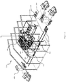
- FIG. 1 depicts an embodiment of an ICV Treatment Facility 1 (also referred to herein as GeoMelt Treatment Facility.
- GeoMelt describes a process based on the principle of vitrification, the process by which a vitrified product with embedded contaminates is formed).
- the depicted ICV Treatment Facility 1 comprises an ICV processing area 515, IX media handling system 510, ICV cooling 520, ISM vessel processing 300, and an off-gas treatment system 560.
- Spent ISM vessels 100 are transported from storage for processing. In some embodiments, the ISM vessels 100 are transported in localized shielded containment 200. The ISM vessels 100 are transferred into the ISM vessel processing area 300 where they are prepared for IX media removal.
- ICV containers 400a are transported from storage or a vessel preparation area.
- the ICV containers 400a will be placed on a transfer system 416 which may include rails 352 for simple transport through the ICV Treatment Facility 1.
- the IX media is removed from the ISM vessels 100 and transferred into an IX handling system 510 where the IX media may be combined with additives to increase efficiency of vitrification.
- the IX media which in some embodiments is mixed with one or more additives, will then be transferred to an empty ICV container 400b.
- the IX media may then be vitrified in the container 400b. As vitrification is being carried out, the volume of material within the ICV container 400b will decrease so IX media may be added throughout the process until the ICV container 400b is full.
- a central control room may provide for monitoring and control of operations.
- monitoring and control operations may be performed at a remote location and or may be mobile. Further, monitoring and control operations may be a combination of one or more of on-site, remote, and mobile.
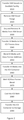
- Figure 2 depicts a flow diagram showing an ICV process for converting spent ISM to stable glass using systems such as those depicted in the embodiment of Figure 1 . Steps in the process embodiment depicted in Figure 2 are generally:
- the ISM processing area 300 receives four vessels at a time, however other amounts are possible.
- the IX media may be removed and delivered to the ICV container through a pneumatic transfer system.
- a skid-mounted off-gas system treats gaseous effluents from the ICV operation 515 and IX media vessel process area 300.
- An ICV container cool-down area 520 is provided to hold containers 400c until they are ready for shipping to an Interim Storage Facility.
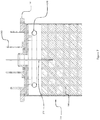
- Figure 3 depicts an embodiment of an ICV container 400 comprising outer shielding 457, refractory lining 431, feed port 411, starter path (not shown), electrodes 421, and lid (built in hood) 458 which may be assembled in an ICV container preparation area.
- the refractory lining 431 may comprise one or more layers of differing materials.
- the outer shielding 457 is steel.
- a starter path which may comprise a mix of moderately conductive materials (comprising glass frit and graphite flake, in some embodiments) may be installed on top of the base primary refractory layer 431. Electrodes 421 are installed into the starter path and held in position until the ICV container lid 458 is installed.
- the electrodes 421 are composed of graphite. In some embodiments the electrodes 421 are 150 mm in diameter. In some embodiments, two or more electrodes 421 may be utilized.
- One function of the lid 458 (built in hood) is to contain and direct the process off-gas to an off-gas treatment system 560 ( FIG. 1 ).
- the lid 458 may comprise electrode penetration/seal 415 assemblies that keep the electrodes 421 in contact with the starter path while providing electrical insulation between the electrodes 421 and the ICV container 400.
- the ICV container 400 in some embodiments may be designed such that four ICV containers 400 may fit in each Interim Storage Facility culvert 600, as depicted in Figure 4 . In some embodiments each ICV container 400 may contain approximately four tonnes of glass.
- Process Hazards Analyses may be performed at least once for each facility, regularly, or intermittently to ensure the safety of the process. Areas of focus for the Process Hazards Analyses may comprise retrieval and transfer of the spent ISM, the processing in the ICV container, and the off-gas treatment. The following factors relate to increasing the safety of the process:
- Spent strontium (Sr) ISM vessels 100 in some embodiments may be retrieved one at a time in order to use an existing transportation cradle, in some embodiments.
- Use of an existing transportation shield 200 may provide stability for the ISM vessel 100 during transport.
- ISM vessel 100 preparation may be performed at an Interim Storage Facility to take advantage of the concrete culvert shielding.
- one or more of the processes described herein may be mobile and or modular such as those described in Mobile Processing System for Hazardous and Radioactive Isotope Removal, Ser. No. 14/748,535 filed June 24, 2015 , with a priority date of June 24, 2014.
- the crane or other lifting device 375 may place the one or more ISM vessels 100 into stations on rails 352 to convey them into the ICV Treatment Facility 1 ( FIG. 1 ) ISM vessel processing station 300 for subsequent processing.
- Hoses 120 may be connected to an air manifold 350 for drying similar to the Dewatering Station currently used for ISM vessels 100.
- the shield lid may be removed to allow access to the top of the ISM vessel 100.
- Spent ISM vessels 100 may have different designs depending on company of manufacture, date of manufacture, and other variables.
- the processing station 300 may utilize a flexible design to handle multiple vessel configurations in the bays and/or expand to have additional bays or end effectors specific to different vessels.
- the shield lid 121 may be removed to provide access to the top of the ISM vessel 100.
- a bridge crane, or other lifting device located in the GeoMelt Treatment Facility 1 ( FIG. 1 ) is used to remove the shield lid 121 ( FIG. 5 ).
- the pressure relief piping 116 connected to the top of the central flange 150.
- this will be done using a shearing tool 140 that may be hung from a load balancing tool holder.
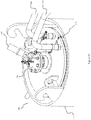
- the shearing tool 140 may be manipulated with either long reach tools or Master-Slave Manipulators (MSMs). Two cuts may be required to remove this small bore piping 116. Shearing may provide improved control over the cut and present reduced risks. Other methods from those described herein also may be utilized to remove the small bore piping 116 such as waterjet cutting and saw cutting methods. After the small bore piping 116 on the flange 150 has been removed, a tool for removal of the central flange 150 can be installed. In the depicted embodiment of Figure 6B , the cutting tool is a waterjet 160. Other cutting methods are contemplated. The tool 160 may be deployed from an overhead mount (not depicted) which lowers the tool 160 over the flange 150.
- MSMs Master-Slave Manipulators
- a pressurized mixture 162 (typically water and garnet) may be used to "cut" the top ISM vessel flange 150.
- the cutting tool 160 has a waterjet head 158 on one leg of a clamp mechanism 113. In the depicted embodiment, the entire tool 160 rotates during cutting to separate the stub pipe 114 below the flange 150.
- the clamp 113 opposite the waterjet cutter 160 may comprise a plate 112, composed of tungsten carbide in some embodiments, which is capable of dispersing any remaining water 162 which exits the cut. This plate 112 serves to prevent accidental cutting of other parts in the vicinity.
- the majority of the limited quantity of water will typically be collected in the ISM vessel shield annular space which is the area between the ISM vessel 100 and the shield 115. Some water may enter the ISM vessel 100. During cutting, a small suction may be applied to the inside of the ISM vessel 100 to ensure that once the ISM vessel 100 is breached any airflow will be into the ISM vessel 100 and no contamination will escape.
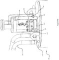
- Clamp 113 may secure the tool 160 during cutting. Once the cut is complete, the clamp 113 may further grip the flange 150 and remove it, as depicted in Figure 6D . In some embodiments the flange 150 may be retrieved using a tool that may be separate or included as part of the waterjet cutting system 160. Once the flange 150 is removed, a temporary cover may be placed over the nozzle opening (outlet) 161 for the drying of the spent IX media.
- a sampling tool 159 may comprise a small bore pipe with an internal auger. The sampling tool 159 may be drilled down the entire height of the ISM vessel 100, if necessary, to retrieve a full vertical profile of the ISM media 166. Sampling tool 159 may be deployed from a top end of ISM vessel 100 similar to the waterjet 160 ( FIGS. 6B-6D ) or vacuum tool 705 ( FIGS. 8A-8C ). A sample core may be extracted from inside of the sampling tool 159, placed into a sample transfer tube, and sent for radioassay or other analysis.
- a temporary cover may be installed over the nozzle opening 161 prior to drying IX media 166. This is done to mitigate potential dusting of dried IX media 166 to the facility 1 ( FIG. 1 ) and to seal the ISM vessel 100 so that heated dried air can be drawn through the ISM vessel 100. Drying of the IX media 166 may be accomplished by drawing under vacuum heated, dry air through the IX bed 166 from the air manifold 350 ( FIG. 5 ). The flow of air is in the direction of normal water flow (i.e., top to bottom). At the outlet 161 of the ISM vessel 100 the humidity of the air is measured to provide an indication of the presence of free water in the ISM vessel 100.
- the temporary cover on the nozzle opening 161 may be removed to allow access to the interior of the ISM vessel 100.
- retrieval of dried spent IX media 166 is accomplished using pneumatic vacuum system 705, which in some embodiments may be negative pressure.
- the vacuum retrieval tool 705 may be mounted to the top of the ISM vessel 100. In some embodiments, it may mate and seal to the top surface of the ISM vessel 100. A central vacuum tube in the vacuum tool 705 may then be deployed down into the dried IX media 166.
- IX Media 166 may be vacuumed by an end effector at the end of a remote manipulator arm and transferred to a receiver unit (not shown) that separates the dried IX media 166 from the air stream using a cyclonic separator or other separation techniques known in the art.
- the receiver unit may be shielded and sized to limit the amount of material present (to assist in the control of dose and minimize risk from upset conditions).
- the receiver unit may be equipped with one or more filters that collect dust material prior to discharge of the air to an off-gas treatment system 560 ( FIG. 1 ) .
- the air may be discharged through a blower. Filtration may be accomplished by a filter, a high pressure HEPA filter in some embodiments, which, when spent, is compatible with processing inside an ICV container 400 ( FIG. 3 ).
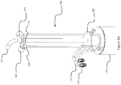
- the top of the vacuum tool 705 is a rotary union 375 and vacuum outlet 331. This allows the vacuum tool 705 to rotate without rotating the vacuum outlet 331. Movement is controlled by a rotary drive mechanism 360 which rotates the vacuum tool 705 and a vertical drive mechanism 365 which drives it up and down with a set of screws. Also below the drives is a rotary union 370 for pressured air which feeds the mixing jets 750 ( FIG. 8B ).
- the end of the vacuum tool 705 in the depicted embodiment is a suction head 701.
- the suction inlets 711 are placed on one side of the suction head 701 and on the other side are pressurized air jets 750. In some embodiments there are three pressurized air jets 750. This allows for material to be drawn into the suction head 701 on one side and blown away on the other. Because the ISM vessel 100 is typically round, this flow of air will circulate the IX media 166 from one side of the ISM vessel 100 to the suction side of the tool 705.
- the pneumatic jets 750 may also cut and mix the IX media 166. This will move any IX media 166 that is cohered together or outside the range of the vacuum 705.
- the bottom of the suction head 701 may comprise a grinding plate and cutting edges 720 which mechanically grind any material below the head 701.
- the suction tube may be rotated slowly and moved down in to the ISM vessel 100 repeatedly.
- a clear window in the vacuum tool 705 will allow operators to see IX media 166 in the suction flow to determine if the tool position is effective or not. This process will continue downward until all IX media 166 has been removed from the ISM vessel 100.
- FIGS 9A and 9B depict the vacuum tool 705, which is not part of the present invention, in use in an ISM vessel 100.
- the air jets 750 blow the IX media 166 on one side of the ISM vessel 100 towards the ISM vessel wall where it is deflected toward the other side.
- a vacuum inlet 711 on the opposite side of the tool 705 pulls in the IX media 166.
- the emptied ISM vessel 100 will then be free of material with only potential surface contamination present.
- ISM vessels 100 may be size reduced by crushing or shredding and are assumed to be considered low-level waste. In some embodiments, the ISM vessels 100 may be modified for reuse.
- Preemptive testing shows the viability of using a vacuum tool 705 to remove the IX media 166 from the ISM vessels 100.
- two beakers were filled with IX media 166, and soaked in a 2.5% salt solution in water. The saltwater was decanted off after 24 hours and the first beaker was oven dried for 24 hours at 150°C. The second beaker was left out on a benchtop for 48 hours for the purpose of testing wet IX media 166. The compaction of the wet and dry IX media 166 was tested prior to the vacuum test. The contents of each beaker were then vacuumed using a standard shop vacuum.
- the testing showed that the vacuuming of both the wet and dry IX media 166 was successful; however, the vacuuming of the dried IX media 166 was easier and quicker than vacuuming the wet IX media 166. The testing validated that the IX media 166 could be readily vacuum extracted.
- sluice systems 2400 may be added to the ICV Treatment Facility 1 ( FIG. 1 ) to retrieve sludge and other wet waste streams from ISM vessels 100.
- the sluice system 2400 is modular.
- the sluice system 2400 is mounted on a mobile skid.
- the ISM vessels 100 may be delivered to the ISM vessel processing station 300 ( FIG. 1 ) which may be comprise a sluice system 2400 including remotely operated sluicing wands (not depicted).
- the sluice system 2400 comprises equipment capable of injecting water into ISM vessels 100 containing spent IX media, mixing the water with the spent IX media, and pumping the resulting sludge out of ISM vessels 100.
- the water is injected and mixed with the IX media using a sluicing wand.
- the sludge is pumped from the ISM vessels 100 using a pump 2440.
- the sludge is processed in a centrifuge 2415, which removes bulk water yielding dewatered effluent.
- the bulk water recovered from the centrifuge 2415 may be recycled through the sluicing wand as needed to assist in sludge removal from ISM vessels 100.
- Dewatered effluent may feed into an auger 2425 which continues the drying process.
- the auger 2425 is heated by heater 2430.
- the auger is hydraulic.
- the dry particulate exiting the auger 2425 may feed into a hopper 531 ( FIG. 11 ) that has an outlet at the bottom that is capable of coupling with a transfer system 521 ( FIG. 11 ).
- the off-gas from the sluice system 2400 may be captured and processed by the off-gas treatment system 560 ( FIG. 1 ).
- the sluice system 2400 may be deployed as a mobile system to retrieve sludge from the storage tanks and provide a dry material to transport back to the ICV Treatment Facility 1 ( FIG. 1 ).
- the IX media 166 is transferred vertically above the GeoMelt ICV container 400 by a pneumatic transfer system 521.
- the pneumatic transfer system 521 is negative pressure.
- the hopper 531 size has been minimized (approximately 50 kg) in order to minimize the amount of material at risk.
- the IX media 166 may be blended with additives and fed into an ICV container 400 by screw feeders, or other feed rate control systems.
- the pneumatic transfer system 705 ( FIGS. 8A-9B ) for the IX media 166 is typically separate from the transfer system 521 for the non-contaminated additives for safety reasons.
- Spent IX media 166 is blended with additives (also referred to herein as "frit”, “glass formers”, and “glass chemistry modifiers”) needed to produce a durable, leach-resistant glass waste form capable of meeting or exceeding industry standards.
- additives also referred to herein as "frit”, “glass formers”, and “glass chemistry modifiers”
- blending may take place in batches as individual ISM vessels 100 are emptied through pneumatic vacuum 705 retrieval.
- IX media 166 and additives may be blended as dry reagents inside a receiving unit such as an enclosed, shielded hopper.
- the receiving unit may be sized to be compatible with the ICV processing rate of 150 kg/hr.
- the receiving unit may be fitted with one or more mixing blades that will blend the dry IX media 166 with additives while preventing caking or buildup in the container.
- the blended material may be fed into the ICV container 400 ( FIG. 3 ) to fill it one-third to one-half full.
- the initial fill level may vary.
- Electrodes 421 ( FIG. 3 ) are used to conduct electricity for the thermal process, which converts the IX media 166 from a solid to a molten state.
- the thermal process is joule-heated.
- the blended material is converted to a molten state, the occupied volume within the ICV container 400 ( FIG. 3 ) will decrease as the material being treated densities.
- additional blended material may be added until the process fills the ICV container 400 ( FIG. 3 ).
- Inlet air used to cool the process and gases generated from the thermal process may be collected and treated in an off-gas treatment system.
- IX media are engineered zeolite-based aluminosilicate materials that will form a glass without additives. However, some additives may be used to maintain the processing temperature at or below 1250°C, in order to minimize Cs volatility.
- the whole rock oxide analyses of a few selected IX media (KUR-H, KUR-EH, and IONSIV IE-96) are shown in Table 1.
- KUR-H, KUR-EH, and IONSIV IE-96 contain relatively high proportions of the principal glass forming oxides; silica and alumina. While such compositions will make excellent glass, they will result in melt temperatures on the order of 1700 to 1800°C.
- the processing temperature may be lowered to 1250°C by the addition of melt temperature and viscosity modifiers; i.e., sodium, calcium, and boron; the corresponding reagents to be added are sodium carbonate (Na 2 CO 3 ), calcium carbonate (CaCO 3 ), and boric oxide (B 2 O 3 ).
- compositions given in Table 1 were used in conjunction with fixed values of boric oxide expressed as a weight percentage of the final glass.
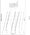
- the amount of CaO and Na 2 O were then varied while holding the calculated melt temperature to 1250°C. Curves expressing these calculations are shown in Figure 12 .
- data runs using 8, 10, and 12 weight percent (wt%) boric oxide (B 2 O 3 ) were performed.
- For each run five different weight percentages of CaO were input and a 1250°C was solved for by using the Goal Seek feature of MicrosoftTM Excel to vary the amount of sodium oxide. From the graphs a continuum reflecting the percentages of CaO and Na 2 O for each boric oxide (B 2 O 3 ) percentage were obtained.
- the retrieved dry material may be blended with a glass former mixture tailored for the specific type of IX media 166.
- glass former mixture and IX media 166 may be fed into a screw feeder, or feed rate control system, that provides mixing and conveys the feed to the ICV container 400 as a relatively homogeneous feed stream, as described earlier in this disclosure.
- the GeoMelt ICV process may be most efficient when used on inorganic waste matrices.
- Organic wastes can, however, be accommodated if combined with sufficient quantities of glass forming minerals (GFMs).
- GBMs glass forming minerals
- the organic content of the resulting mixture should contain no more than 30 wt% organic content in some embodiments.
- Spent organic adsorbents stages can be treated in much the same manner.
- Glass formers can include KUR-H or KUR-EH ISM along with adjunct materials such as boric oxide, soda ash, and lime to act as fluxing agents.
- the amount of titanium oxide that can be incorporated into the glass may include amounts up to 25 wt%.
- titanium oxide is amenable to the same treatment.
- This adsorbent is assumed to be titanium dioxide subjected to a surface treatment that optimizes the adsorption of antimony (Sb).
- a commercial example of the product would be Metsorb ® HMRG by Graver Technologies.
- the surface treatment compounds may not materially affect the gross composition of the resultant glass. Acting on this assumption a glass recipe may be formulated quite easily, provided that the maximum concentration of TiO 2 in the resultant glass is stipulated.
- Zeolites generally have compositions that result in adequate glasses without amendments.
- fluxing agents may be added, as will be done with KUR-H and the other ISMs.
- Activated carbon can be treated by GeoMelt ICV, but may result in an extremely reducing environment.
- a source of oxygen may be introduced, either chemically or by bubbling.
- GeoMelt ICV can be used for much of the wastes produced in removing harmful radionuclides from the water. Waste treatment strategies may be implemented where some significant synergies exist, since the processing of organic resins or sludges may need blending with quantities of GFMs.
- titanate could be blended with KUR-H, KUREH, or IONSIV-96 to provide the bulk of the required GFMs.
- the GFMs could be spent inorganic ISM and mixed with other waste streams while ensuring not to exceed established site worker dose objectives.
- Spent KUR-EH could be used as the GFMs for the titanium and all of the organic streams.
- ICV container 400 ( FIG.3 ) preparation comprises of installation of base and side refractory support blocks and panels within a base layer.
- the base layer is comprised of silica sand.
- the base layer provides secondary containment and freezing of any molten material that may migrate from the primary refractory lining (not depicted).
- the primary refractory lining comprises of larger monolithic precast panels that are installed inside and above a secondary refractory lining 431.
- the refractory used in some embodiments of the ICV process may be an aluminosilicate clay mineral-based material similar to that widely used in the steel industry for the lining of blast furnaces and can withstand severe high temperature corrosive environments.
- the design of refractory sand and refractory panels disclosed herein is a scaled-down version of a previously validated design demonstrated for ICV containers 400 holding fifty metric tons of glass.
- the ICV containers 400 may be prepared in advance of arriving at the site or they may be prepared on-site.
- the refractory lining 431 may be approximately 300 mm thick at the base and 200 mm thick on the sides.
- the refractory base is typically thicker than the refractory sides to reflect the longer exposure on the bottom to the molten glass and to provide structural strength.
- the ICV container 400 in some embodiments comprises of 6-inch thick carbon steel walls and base, which, with the refractory lining 431 provides appropriate shielding.
- a stainless steel, or other appropriate shielding material, outer shielding 457 may be implemented to ensure corrosion resistance.
- a starter path which may comprise a mix of moderately conductive glass frit and graphite flake, may be installed on top of the base primary refractory layer 431 in some embodiments. Electrodes 421 are installed into the starter path and held in position until the ICV container lid 458 is installed. In some embodiments, the electrodes 421 are composed of graphite. In some embodiments the electrodes 421 are 150 mm in diameter. In some embodiments, two or more electrodes 421 may be utilized.
- the lid 458 (built in hood) contains and directs the process off-gas to an off-gas treatment system 560 ( FIG. 1 ). In some embodiments, the lid 458 comprises electrode penetration/seal 415 assemblies that keep the electrodes 421 in contact with the starter path while providing electrical insulation between the electrodes 421 and the ICV container 400.
- the ICV container 400 is designed to receive the waste/glass former mixture, contain the vitrification process, and serves as the final disposal container for the vitrified waste.
- the ICV container 400 provides primary containment for waste received from the ISM vessels 100, the molten glass during processing, and the final waste product.
- the assembled ICV container 400 is moved to the ICV processing area by crane or other lifting/hoisting device. Once in the ICV processing area, the ICV container 400 is connected to the off-gas treatment system 560 ( FIG. 1 ) and to the feed system, through ports in the ICV container lid 458. Instrumentation, such as thermocouples and infrared camera systems, may be connected to the wiring harness, the electrodes 421 are connected to the power system, and the ICV container 400 is grounded to the structural steel that supports the feed system and electrode feeders.
- Waste and additives are conveyed into the ICV container 400 by a feed system.
- the initial batch and subsequent batches are fed to a predetermined level in the ICV container 400 correlated to volumetric discharges and verified by observation, which may comprise at least one infrared camera system in some embodiments.
- the waste and additives are melted inside the ICV container 400 using electrical power supplied by the electrodes 421.
- a starter path may be used to initiate the melt at the base of the first batch feed pile. As melting ensues, the waste mixture densifies creating additional volume in the container allowing for additional waste to be fed and processed.
- the nominal power level required for processing in some embodiments is approximately 400 kW.
- the processing rate in some embodiments may be 150 kg/hr.
- each ICV container 400 may hold 4000 kg of glass, based on the volume available inside the refractory lining 431 and the density of glass.
- LOI loss on ignition
- the mass of material that is converted to gas primarily CO 2
- each ISM vessel 400 contains approximately 800 kg of IX media 166.
- each melt will process the contents of approximately four ISM vessels 100.
- Total melt duration, at a processing rate of 150 kg/hr of total feed material (ISM and glass formers) will be approximately 33 hrs.
- Table 3 Component Mass (kg) Kurion H and EH ISM 3,550 Soda Ash (NA 2 CO 3 ) 467 Lime (CaCO 3 ) 402
- Off-gas evolving from ICV plus balance air constitutes the off-gas routed to off-gas treatment 560 ( FIG. 1 ).
- IX media melting evolves negligible noxious volatiles requiring abatement (e.g., NO x or SO x ), so the off-gas contaminants of interest are primarily particulate entrainment and volatile Cs. The extent of Cs evolution is dependent on the melter operating temperature.
- the primary volatile from ISM melting is simply water vapor.
- Dry IX media such as KUR-H, KUR-EH and UOP IONSIV IE-96 can contain water within the particles (up to 30% moisture content) that is quantitatively evolved during melting which must be managed in the off-gas system 560 ( FIG. 1 ).
- the off-gas system 560 ( FIG. 1 ) comprises of the following stages:
- the off-gas system 560 ( FIG. 1 ) may operate continuously to maintain draft through the drying station and through the ICV container 400 when processing IX media. Air from the drying station may be introduced into the final conditioning stage as it requires only HEPA filtration before discharge.
- Off-gas from the ICV container 400 may be passed through a backpulsable sintered metal filter (SMF).
- SMF stage in some embodiments comprises of two filters in parallel. In some embodiments more than two filters are configured in parallel. In some embodiments one or more filters may be included in series. The parallel configuration allows one filter to be taken out of service and the other brought online when recycling collected solids.
- the SMF is located with sufficient elevation that particulate is returned to the ICV container 400 by gravity feed. In some embodiments, the SMF is located at a lower elevation with return to the ICV feed hopper by pneumatic transfer. SMFs are rated at 98.3 percent removal efficiency for 0.3 ⁇ m particulate. The off-gas entering the SMF may be sufficiently hot that condensation is precluded.
- HEPA filters may be used. Baghouse filters may be used, however, long-term integrity of baghouse filters would be suspect in radioactive application. Additionally, standard High Efficiency Particulate (HEPA) filters may be used. The use of standard HEPA filters as a pre-filter would require physical change-out when the change in pressure approached the filters design pressure drop causing worker exposure issues and additional secondary waste that would have to be processed in the container. A cleanable filter such as the SMFs proposed is a much more efficient approach from a processing standpoint, greatly reduces worker dose and allows for chemical cleaning of the sintered filter in place and remotely.
- HEPA High Efficiency Particulate
- the off-gas exiting the SMF may be high temperature.
- the off-gas may be contacted with recirculating working fluid in tandem venturi scrubbers.
- the venturi scrubbers may be mounted directly on a scrub tank.
- the tank may be equipped with an internal baffle to ensure that air flows through both venturi scrubbers in series.
- the function of the scrubbers is to condense volatile cesium, and remove fine particulate that penetrates the SMF.
- varying amounts of scrubbers may be used in different configurations including parallel and in series.
- treated air exiting the scrub tank is saturated with water vapor and entrains water droplets, thus the exiting air passes through a filter, which may be a High Efficiency Mist Eliminator (HEME).
- a filter which may be a High Efficiency Mist Eliminator (HEME).
- HEME High Efficiency Mist Eliminator
- contaminated working fluid from the venturi scrubbers collects in the scrub tank, it may circulate through an external loop to be processed through one or more filters to remove particulate, through selective ion exchange to remove soluble cesium, and through a cooler (as needed) before it is introduced at the venturi scrubber.
- Periodically spent filters and ISM may be transferred to the in-preparation ICV container 400 to be included in a subsequent melter run.
- spent working fluid may be pumped out to an operating melter. Soluble components are retained in the melt and water is evaporated to be released through the off-gas treatment system 560 ( FIG. 1 ).
- the air passing through the scrubber system may become saturated with water, thus water accumulation can be regulated by adjusting the operating temperature.
- the ideal operating temperature of the wet scrubber system is the temperature that prevents net accumulation of water.
- There is a primary cooling effect in the venturi scrubbers as the passing air saturates with water vapor. Additional cooling of the circulating working fluid (as needed) can be applied in the external loop.
- the working fluid of the wet scrubbing system can become acidic over time from the capture of acidic gases depending on the waste types being processed.
- the scrubbing system may include a caustic storage tank and pH adjustment tank to automatically regulate the pH of the working fluid.
- Treated off-gas exiting wet scrubbing may be saturated with water vapor.
- the treated off-gas may be heated (nominally 15°C in some embodiments) to reduce relative humidity prior to final filtration.
- Final conditioning of the off-gas before discharge may be by HEPA filtration, though other filtration methods are possible.
- HEGA filtration in addition to HEPA filtration for removal of organic carbon and radioiodine may be utilized in some embodiments.
- exhaust fans there are one or more exhaust fans.
- two exhaust fans are configured in parallel.
- One fan may operate continuously and the other may be on standby.
- the exhaust fans provide the motive force to move exhaust gases and vapors through the off-gas train, while maintaining the required vacuum in the ICV container 400.
- Variable frequency drives may be used to control fan speed.
- the exhaust stack may be designed to disperse treated gases to the atmosphere in compliance with local regulations.
- the exhaust stack may be equipped for flow monitoring, and may be equipped with all sample probes and devices required for stack gas analysis, data collection, and regulatory reporting. Stack monitoring may comprise one or more of the following:
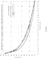
- Cooling of the ICV container 400 may take place in the ICV cooling area 520 ( FIG. 1 ). Cooling of the molten glass may take place within the processing duration of subsequent melts so that there is no accumulation of finished melts in the Geomelt Treatment Facility 1 ( FIG. 1 ). Referring to Figure 13 , based on cooling data for a much larger ICV system than that described herein, each ICV container 400 may cool to 700°C within two days. At 700°C, the glass will be solid, therefore eliminating any accident scenario involving molten glass exiting the ICV container 400 while being loaded or transported to an Interim Storage Facility.
- Table 5 compares GeoMelt glass samples with standard specifications of high-level vitrified waste produced by JNFL and JAEA.
- the MCC-1 values for the JNFL and JAEA glass is given as Bulk Leach Rate (BLR, or total mass of all elements released), and are not directly comparable to PCT test results given above in Table 4.
- BLR Bulk Leach Rate
- Table 5 compares JNFL (Rokkasho) and JAEA specifications with GeoMelt glass MCC-1 results. Note that the GeoMelt glass sample was subjected to an extended MCC-1 test duration (1557 days), and the results indicate that the dissolution rate from GeoMelt glass decreases with time.
- the chemical composition of the media is typically well known and consistent which provides a uniform feed stream from a glass former standpoint; however, the concentration of the radionuclides loaded onto the media in an ISM vessel can vary to some degree both vertically and radially within the ISM vessel.
- the loaded media is removed from the ISM vessel and transported using conventional material handling mechanisms such as with the pneumatic system proposed herein to transfer the waste feed to the ICV container loading mechanism, mixing of the media occurs which serves to distribute and further mix the radionuclide inventory thereby providing a more uniform feed prior to vitrification.
- homogeneity of the resulting glass product has been consistently demonstrated. Homogeneity is typically enhanced during vitrification due to convective currents that are formed within the melt environment. These convective currents induce a flow and mixing within the molten waste that is highly effective in uniformly distributing both contaminant species and glass forming minerals to produce a consistently homogeneous and durable final product.
- the benefits of a homogenous waste form are many and include the following:
- samples of the glass are collected both during the melting process and/or after the melt has cooled that allow for sample analysis to occur which can then be used to show homogeneity as well as other sample data of interest.
- the post melt sampling has proven to be very flexible and effective as an entire core sample of the treatment container can be collected either vertically or horizontally to provide representative samples of the vitrified product available from any location in the ICV container. Based on an unbiased sampling approach, glass samples from select intervals of the cores may be taken and submitted for appropriate analytical analysis (such as ⁇ / ⁇ counting, ICP-MS, or XRF).
- GeoMelt ICV glass is typically 5 to 10 times stronger than concrete in both tensile and compressive strengths. This strength is a benefit that helps minimize the potential for human and animal intrusion. Although the vitrified product is strong, it can be broken into manageable pieces and handled with conventional heavy equipment. Table 6 shows the strength and other advantages of GeoMelt glass compared to concrete. Table 6 Physical Property GeoMelt Glass Grout/Concrete Chemical Durability (years) ⁇ 10 4 - 10 6 10 2 Waste Loading Generally Higher Limited Compressive Strength (psi) 40,000 - 60,000 3,000 - 8,000 Tensile Strength (psi) 4,000 - 4,400 400 - 600 Final Volume Decrease Increase
- sulfur salts can increase the volatility of radionuclides such as cesium.
- Such occurrences are known to be problematic with conventional joule-heated melters. These melters are continuously fed and discharge from midlevel or the bottom of the melt chamber. This allows amounts of sulfur to accumulate over time on the surface, even if the feed has initially low sulfur content. Since they discharge from below the surface of the melt and the sulfur salts accumulate at the top, the salts are never allowed to discharge.
- the GeoMelt ICV melter is, in contrast, a batch operation where the melt and disposal vessels are one and the same. Provided that the raw feed does not exceed the sulfur limits imposed by the glass formulation there is not an opportunity for a sufficient amount of sulfur salts to accumulate to the point of being problematic. Much work on chemical modification to the waste feed stream has been done such as the demonstration of adding barium to increase sulfur solubility.
- the addition of barium may increase the molten pool viscosity into a range where conventional melters cannot operate due to their inability to pour or drain their melters.
- the GeoMelt ICV process described herein is a batch process thus it does not require a pouring of glass. As a batch process it is capable of accommodating such formulation modifications as means to increase the sulfate loading.
- the primary waste streams targeted for this concept do not contain sulfur in concentrations exceeding the glass solubility limit so it is unlikely there will be any sulfur-related difficulties.
- Each completed ICV container 400 may be returned to the Interim Storage Facility. Alternatively, each completed ICV container 400 ( FIG. 3 ) may be moved to a permanent storage facility. In some embodiments, the ICV container 400 ( FIG. 3 ) is sized such that four containers fit into each culvert 600 as depicted in Figure 4 . In some embodiments, each culvert 600 may contain the contents of sixteen ISM vessels 100.
- the GeoMelt ICV process may employ a power system which allows for variable power levels to the melt environment and variable voltage levels to be able to accommodate changes in melt resistance due to different waste properties and changes in the size of the melt.
- the power system may be divided into two main areas: 1) the power supply to the melt which provides the power for the melting process (which may be joule-heated in some embodiments), and 2) ancillary power to the balance of the system for such items as off-gas components (fans, pumps, heaters), instrumentation, heating and air conditioning (HVAC), lighting, and other low voltage needs such as for process control and data acquisition and facility needs.
- off-gas components fans, pumps, heaters
- HVAC heating and air conditioning
- the power supply system to the melt may employ a 600 kVA Scott-Tee connected transformer in some embodiments that produces variable voltage output through a range of operator selectable voltage taps. Power output is controlled at the primary side of the transformer with silicon control rectifier (SCR) technology, which uses a single potentiometer selectable for either voltage or current control.
- SCR silicon control rectifier
- the Scott-Tee transformer is a system to convert primary 3-phase power (three-wire) to two secondary phases.
- Transformers typically have several separate voltage tap settings ranging from >1000 volts to ⁇ 150 volts.
- the voltage taps have corresponding increasing current ratings of similar amps per phase (150 A to >1000 Amps, respectively).
- the power supply to the other ancillary equipment such as the off-gas system, HVAC, lighting, pneumatic system, facility, etc. may typically be on the order of 150 - 200 KVA and may be designed to transform incoming power into voltages and frequencies applicable to the levels required for the equipment such as that designed for eastern Japan.
- a backup diesel generator may be utilized to provide energy for the operation of all essential equipment for personnel and environmental safety in the event that utility line power is interrupted. These include the off-gas system, data acquisition system, environmental and system monitoring equipment, heating and air conditioning, and system lighting. Activation of the generator is automatic upon the loss of utility line power, thus providing uninterrupted power to essential process equipment. Additionally, if the availability of grid power is limited due to remoteness or limited capacity, the entire power system can be designed to be supplied by a combustion-based generated power system. Additionally, power generation may be augmented by one or more alternative methods such as solar and wind power.
Landscapes
- Physics & Mathematics (AREA)
- Engineering & Computer Science (AREA)
- General Engineering & Computer Science (AREA)
- High Energy & Nuclear Physics (AREA)
- Chemical & Material Sciences (AREA)
- Inorganic Chemistry (AREA)
- Organic Chemistry (AREA)
- Chemical Kinetics & Catalysis (AREA)
- Processing Of Solid Wastes (AREA)
Claims (13)
- System zur Aufbereitung verbrauchter lonenaustauschmedien (166), das Folgendes umfasst:ein Gefäß (100) für ionenspezifische Medien (ISM-Gefäß), wobei das ISM-Gefäß verbrauchte lonenaustauschmedien enthält;ein Trocknungssystem (350) zur Trocknung der verbrauchten lonenaustauschmedien;ein Entnahmesystem zur Entnahme der getrockneten, verbrauchten Ionenaustauschmedien aus dem ISM-Gefäß;ein Mischsystem zum Mischen der getrockneten, verbrauchten Ionenaustauschmedien mit Zusatzstoffen;ein Verglasungssystem zum Verglasen der gemischten Ionenaustauschmedien und der Zusatzstoffe in einem Verglasungsbehälter (400), das so ausgeführt ist, dass es ein verglastes Produkt mit eingebetteten Schadstoffen ergibt;dadurch gekennzeichnet, dass das Entnahmesystem ein Schleusensystem (2400) umfasst, das Geräte umfasst, die in der Lage sind, Wasser in das ISM-Gefäß einzuspritzen, das Wasser mit den verbrauchten lonenaustauschmedien zu vermischen und den entstehenden Schlamm aus dem ISM-Gefäß zu pumpen, wobei das Schleusensystem ferner eine Zentrifuge (2415) umfasst, die so eingerichtet ist, dass sie einen Großteil des Wassers aus dem Schlamm entfernt, wodurch sich entwässertes Abwasser ergibt.
- System nach Anspruch 1, ferner mit einem Abgasbehandlungssystem zum Auffangen und Behandeln von Abgasen, die von dem Trocknungssystem, dem Entnahmesystem, dem Mischsystem und/oder dem Verglasungssystem freigesetzt werden.
- System nach Anspruch 1 oder 2, bei dem das Trocknungssystem so ausgebildet ist, dass es die verbrauchten lonenaustauschmedien unter Verwendung von erwärmter Trockenluft trocknet.
- System nach einem der vorhergehenden Ansprüche, bei dem die Zusatzstoffe Glasbildner sind.
- System nach einem der vorhergehenden Ansprüche, bei dem das verglaste Produkt mit eingebetteten Schadstoffen homogen ist.
- System nach einem der vorhergehenden Ansprüche, wobei das System so ausgebildet ist, dass es das Volumen des verglasten Produkts mit eingebetteten Schadstoffen aus dem Volumen der verbrauchten lonenaustauschmedien reduziert.
- System nach einem der vorhergehenden Ansprüche, bei dem das Trocknungssystem, das Entnahmesystem, das Mischsystem und/oder das Verglasungssystem auf oder innerhalb von mobilen Gleitkufen und/oder innerhalb einer einzelnen Struktur angeordnet ist bzw. sind.
- Verfahren zur Aufbereitung verbrauchter lonenaustauschmedien (166), das Folgendes umfasst:Trocknen verbrauchter Ionenaustauschmedien, die in einem Gefäß (100) für ionenspezifische Medien (ISM-Gefäß) enthalten sind;Entnehmen getrockneter, verbrauchter lonenaustauschmedien aus dem ISM-Gefäß;Mischen der getrockneten, verbrauchten lonenaustauschmedien mit Zusatzstoffen;Verglasen der gemischten lonenaustauschmedien und der Zusatzstoffe in einem Verglasungsbehälter (400), wodurch verglaste lonenaustauschmedien mit eingebetteten Schadstoffen entstehen;Kühlen der verglasten lonenaustauschmedien mit eingebetteten Schadstoffen, bis sie einen festen Zustand erreichen; undLagern der verglasten lonenaustauschmedien mit eingebetteten Schadstoffen;dadurch gekennzeichnet, dass das Entnehmen der getrockneten, verbrauchten lonenaustauschmedien aus dem lonenaustauschgefäß Folgendes umfasst:Einspritzen von Wasser in das ISM-Gefäß;Vermischen des Wassers mit den verbrauchten Ionenaustauschmedien; undPumpen des entstehenden Schlamms aus dem Ionenaustauschgefäß, wobei ein Großteil des Wassers von einer Zentrifuge (2415) aus dem Schlamm entfernt wird, wodurch sich entwässertes Abwasser ergibt.
- Verfahren nach Anspruch 8, bei dem ferner Abgase, die durch die Trocknung, Entnahme, das Mischen und/oder die Verglasung freigesetzt werden, behandelt werden.
- Verfahren nach Anspruch 8 oder 9, bei dem die lonenaustauschmedien unter Verwendung von erwärmter Trockenluft und/oder Druckluftstrahlen getrocknet werden.
- Verfahren nach einem der Ansprüche 8 oder 10, bei dem die Zusatzstoffe Glasbildner sind.
- Verfahren nach einem der Ansprüche 8 oder 11, bei dem das verglaste lonenaustauschmedium mit eingebetteten Schadstoffen homogen ist und/oder bei dem das Volumen der verglasten lonenaustauschmedien mit eingebetteten Schadstoffen aus dem Volumen der verbrauchten lonenaustauschmedien reduziert wird.
- Verfahren nach einem der Ansprüche 8 bis 12, bei dem einer oder mehrere der Aufbereitungsschritte auf oder innerhalb von mobilen Gleitkufen und/oder innerhalb einer einzelnen Struktur ausgeführt werden.
Applications Claiming Priority (2)
| Application Number | Priority Date | Filing Date | Title |
|---|---|---|---|
| US201562110563P | 2015-02-01 | 2015-02-01 | |
| PCT/US2016/015937 WO2016123606A1 (en) | 2015-02-01 | 2016-02-01 | Ion specific media removal from vessel for vitrification |
Publications (2)
| Publication Number | Publication Date |
|---|---|
| EP3251122A1 EP3251122A1 (de) | 2017-12-06 |
| EP3251122B1 true EP3251122B1 (de) | 2019-04-10 |
Family
ID=55487062
Family Applications (1)
| Application Number | Title | Priority Date | Filing Date |
|---|---|---|---|
| EP16708784.0A Active EP3251122B1 (de) | 2015-02-01 | 2016-02-01 | Entfernung ionenspezifischer medien aus einem behälter für die verglasung |
Country Status (5)
| Country | Link |
|---|---|
| US (1) | US10290384B2 (de) |
| EP (1) | EP3251122B1 (de) |
| JP (1) | JP6835318B2 (de) |
| CA (1) | CA2975285A1 (de) |
| WO (1) | WO2016123606A1 (de) |
Families Citing this family (8)
| Publication number | Priority date | Publication date | Assignee | Title |
|---|---|---|---|---|
| JP6813817B2 (ja) * | 2015-12-29 | 2021-01-13 | ヴェオリア ニュークリア ソリューションズ インコーポレイテッドVeolia Nuclear Solutions Inc. | 電極シールアセンブリの為のシステムおよび方法 |
| US10884393B2 (en) | 2016-05-02 | 2021-01-05 | Veolia Nuclear Solutions, Inc. | Tank cleaning system |
| CA3157531C (en) | 2016-05-26 | 2023-08-15 | Veolia Nuclear Solutions, Inc. | System for storage container with removable shield panels |
| US11440064B2 (en) | 2017-08-17 | 2022-09-13 | Veolia Nuclear Solutions, Inc. | Systems and methods for tank cleaning |
| US11508490B2 (en) | 2020-03-11 | 2022-11-22 | Henry Crichlow | Managing volatiles in nuclear waste vitrification |
| US20250128304A1 (en) * | 2021-08-13 | 2025-04-24 | Veolia Nuclear Solutions, Inc. | Systems and Methods for Vitrification Process Control |
| WO2023141528A1 (en) | 2022-01-24 | 2023-07-27 | Veolia Nuclear Solutions, Inc. | Systems and methods for electrode feeders and electrode seals |
| WO2025188910A1 (en) | 2024-03-05 | 2025-09-12 | Veolia Nuclear Solutions, Inc. | Systems and methods for a multistage melter |
Citations (1)
| Publication number | Priority date | Publication date | Assignee | Title |
|---|---|---|---|---|
| US4383920A (en) * | 1981-05-29 | 1983-05-17 | Ecolochem, Inc. | Mobile fluid purification system |
Family Cites Families (29)
| Publication number | Priority date | Publication date | Assignee | Title |
|---|---|---|---|---|
| US3640888A (en) | 1969-12-11 | 1972-02-08 | Atomic Energy Commission | Californium-252 neutron source and method of making same |
| JPS5011040B1 (de) * | 1970-07-20 | 1975-04-26 | ||
| US4058227A (en) * | 1976-10-12 | 1977-11-15 | Sun Shipbuilding & Dry Dock Company | Pneumatic conveying of granular materials from a nonpressurized environment |
| GB8331031D0 (en) * | 1983-11-21 | 1983-12-29 | Roberts D | Vitrification of asbestos waste |
| JPS6179199A (ja) * | 1984-09-27 | 1986-04-22 | 株式会社東芝 | 放射性廃棄物の固化処理方法および固化処理装置 |
| JPH0750196B2 (ja) * | 1986-12-24 | 1995-05-31 | 動力炉・核燃料開発事業団 | 放射性廃棄物の溶融固化処理装置 |
| JPH01245199A (ja) * | 1988-03-28 | 1989-09-29 | Toshiba Corp | 使用済イオン交換樹脂の輸送方法 |
| FR2682524B1 (fr) * | 1991-10-10 | 1993-12-10 | Matieres Nucleaires Cie Gle | Procede de conditionnement ou de recyclage de cartouches ioniques usagers. |
| JP3278192B2 (ja) * | 1992-04-03 | 2002-04-30 | ロート製薬株式会社 | 徐放性液剤 |
| US5371911A (en) * | 1993-07-23 | 1994-12-13 | Industrial Piping, Inc. | Drum processing apparatus |
| US5424042A (en) * | 1993-09-13 | 1995-06-13 | Mason; J. Bradley | Apparatus and method for processing wastes |
| US5643350A (en) * | 1994-11-08 | 1997-07-01 | Vectra Technologies, Inc. | Waste vitrification melter |
| US6204427B1 (en) * | 1995-12-18 | 2001-03-20 | Thomas L. Eddy | Process and apparatus for the partitioning and thermal treatment of heterogeneous feedstock |
| FI101681B (fi) * | 1996-01-23 | 1998-08-14 | Valtion Teknillinen | Menetelmä radioaktiivisen ongelmajätteen käsittelemiseksi |
| US5678237A (en) * | 1996-06-24 | 1997-10-14 | Associated Universities, Inc. | In-situ vitrification of waste materials |
| JP2000180250A (ja) | 1998-10-09 | 2000-06-30 | Ngk Insulators Ltd | 質量センサ及び質量検出方法 |
| US6329563B1 (en) * | 1999-07-16 | 2001-12-11 | Westinghouse Savannah River Company | Vitrification of ion exchange resins |
| US6283908B1 (en) | 2000-05-04 | 2001-09-04 | Radioactive Isolation Consortium, Llc | Vitrification of waste with conitnuous filling and sequential melting |
| GB0021715D0 (en) * | 2000-09-05 | 2000-10-18 | Ici Plc | Recovery of metals |
| US6558308B2 (en) | 2001-05-07 | 2003-05-06 | Radioactive Isolation Consortium, Llc | AVS melting process |
| US7211038B2 (en) | 2001-09-25 | 2007-05-01 | Geosafe Corporation | Methods for melting of materials to be treated |
| KR100433754B1 (ko) * | 2001-10-29 | 2004-06-04 | 한국전력공사 | 정수처리용 이온교환수지 세정 방법 |
| US6941878B2 (en) | 2002-09-27 | 2005-09-13 | Radioactive Isolation Consortium, Llc | Advanced vitrification system 2 |
| JP4421642B2 (ja) * | 2007-09-05 | 2010-02-24 | 東芝プラントシステム株式会社 | イオン交換樹脂塔への樹脂移送・充填方法 |
| CN101486036B (zh) * | 2009-02-12 | 2010-09-15 | 天津市缘成电子科技发展有限公司 | 吸嘴清洗机 |
| US9981868B2 (en) | 2010-04-02 | 2018-05-29 | Kurion, Inc. | Mobile processing system for hazardous and radioactive isotope removal |
| KR101173832B1 (ko) * | 2012-02-09 | 2012-08-16 | 배상수 | 원자력발전소의 폐수지 건조장치 |
| US8841504B2 (en) * | 2012-08-10 | 2014-09-23 | Daigo Kato | Method for disposal of radioactive waste |
| WO2014194331A1 (en) | 2013-05-31 | 2014-12-04 | Kurion, Inc. | A balanced closed loop continuous extraction process for hydrogen isotopes |
-
2016
- 2016-02-01 US US15/012,101 patent/US10290384B2/en not_active Expired - Fee Related
- 2016-02-01 JP JP2017540614A patent/JP6835318B2/ja active Active
- 2016-02-01 EP EP16708784.0A patent/EP3251122B1/de active Active
- 2016-02-01 WO PCT/US2016/015937 patent/WO2016123606A1/en not_active Ceased
- 2016-02-01 CA CA2975285A patent/CA2975285A1/en not_active Abandoned
Patent Citations (1)
| Publication number | Priority date | Publication date | Assignee | Title |
|---|---|---|---|---|
| US4383920A (en) * | 1981-05-29 | 1983-05-17 | Ecolochem, Inc. | Mobile fluid purification system |
Also Published As
| Publication number | Publication date |
|---|---|
| CA2975285A1 (en) | 2016-08-04 |
| US10290384B2 (en) | 2019-05-14 |
| WO2016123606A1 (en) | 2016-08-04 |
| US20160225475A1 (en) | 2016-08-04 |
| JP2018510762A (ja) | 2018-04-19 |
| EP3251122A1 (de) | 2017-12-06 |
| JP6835318B2 (ja) | 2021-02-24 |
Similar Documents
| Publication | Publication Date | Title |
|---|---|---|
| US10290384B2 (en) | Ion specific media removal from vessel for vitrification | |
| JP6250651B2 (ja) | 熱間等方圧加圧(hip)によって放射性含有物質を圧密化する方法 | |
| US20260115771A1 (en) | Systems and Methods for Vitrification Process Control | |
| Raj et al. | Radioactive waste management in U/Th fuel cycles | |
| Perez Jr et al. | Vitrification testing and demonstration for the Hanford waste treatment and immobilization plant | |
| Raj | Commissioning and operation of high level radioactive waste vitrification and storage facilities: the Indian experience | |
| KR20130055390A (ko) | 방사성 폐기물의 소각후 재처리 방법 및 장치 | |
| Amoroso et al. | Appropriateness and Readiness of Cold Crucible Vitrification of Calcine Solids at the Idaho Site and H-Canyon Effluent at the Savannah River Site | |
| Treat et al. | Preliminary evaluation of alternative waste form solidification processes. Volume I. Identification of the processes | |
| KR20250166059A (ko) | 유리용탕 시료채취 시스템 | |
| DesCamp et al. | Vitrification Facility at the West Valley Demonstration Project | |
| Ford et al. | Minimizing Transuranic Waste Generated in Hot Cells at Oak Ridge National Laboratory Through Use of a Non-Destructive CO2 Pellet Cleaning System | |
| HR et al. | EXPERIENCE AND PROJECTS FOR TREATMENT AND CONDITIONING OF ALL RADIOACTIVE WASTES FROM REPROCESSING PLANTS IN THE FEDERAL REPUBLIC OF GERMANY | |
| Campbell et al. | Commissioning of a GeoMelt Vitrification Plant at the Central Laboratory on the Sellafield Site-17561 | |
| Jean Jacques et al. | Decommissioning of nuclear reprocessing plants French past experience and approach to future large scale operations | |
| Thompson et al. | Status and Direction of the Bulk Vitrification Program for the Supplemental Treatment of Low Activity Tank Waste at Hanford | |
| Stegen et al. | Simplified Melter System Proposed for Vitrification of INEEL High-Level Waste | |
| Larson et al. | Conceptual design of a nuclear waste vitrification facility | |
| Ragheb | Reprocessing and vitrification for nuclear waste consolidation | |
| Thompson | British Vitrification Process Safety Issues | |
| Morrell et al. | Department of Energy treatment capabilities for greater-than-Class C low-level radioactive waste | |
| Babaev et al. | Current Situation and the New Concept of Radioactive Waste Management in Russia | |
| Minichan et al. | Vitrification of actinide solutions in SRS separations facilities | |
| Shah et al. | Hanford waste vitrification plant process description, process advancements, and Hanford site interfaces | |
| Kibbey et al. | Review of solid radioactive waste practices in light-water-cooled nuclear reactor power plants |
Legal Events
| Date | Code | Title | Description |
|---|---|---|---|
| STAA | Information on the status of an ep patent application or granted ep patent |
Free format text: STATUS: THE INTERNATIONAL PUBLICATION HAS BEEN MADE |
|
| PUAI | Public reference made under article 153(3) epc to a published international application that has entered the european phase |
Free format text: ORIGINAL CODE: 0009012 |
|
| STAA | Information on the status of an ep patent application or granted ep patent |
Free format text: STATUS: REQUEST FOR EXAMINATION WAS MADE |
|
| 17P | Request for examination filed |
Effective date: 20170823 |
|
| AK | Designated contracting states |
Kind code of ref document: A1 Designated state(s): AL AT BE BG CH CY CZ DE DK EE ES FI FR GB GR HR HU IE IS IT LI LT LU LV MC MK MT NL NO PL PT RO RS SE SI SK SM TR |
|
| AX | Request for extension of the european patent |
Extension state: BA ME |
|
| RIN1 | Information on inventor provided before grant (corrected) |
Inventor name: CAMPBELL, BRETT EDWARD Inventor name: COLE, MATT DENVER |
|
| DAV | Request for validation of the european patent (deleted) | ||
| DAX | Request for extension of the european patent (deleted) | ||
| GRAP | Despatch of communication of intention to grant a patent |
Free format text: ORIGINAL CODE: EPIDOSNIGR1 |
|
| STAA | Information on the status of an ep patent application or granted ep patent |
Free format text: STATUS: GRANT OF PATENT IS INTENDED |
|
| RIC1 | Information provided on ipc code assigned before grant |
Ipc: B01J 47/016 20170101ALI20180831BHEP Ipc: G21F 9/00 20060101AFI20180831BHEP Ipc: B65G 53/00 20060101ALI20180831BHEP Ipc: G21F 9/12 20060101ALI20180831BHEP Ipc: G21F 9/30 20060101ALI20180831BHEP Ipc: G21F 5/005 20060101ALI20180831BHEP Ipc: G21F 5/14 20060101ALI20180831BHEP |
|
| INTG | Intention to grant announced |
Effective date: 20180921 |
|
| GRAS | Grant fee paid |
Free format text: ORIGINAL CODE: EPIDOSNIGR3 |
|
| GRAA | (expected) grant |
Free format text: ORIGINAL CODE: 0009210 |
|
| STAA | Information on the status of an ep patent application or granted ep patent |
Free format text: STATUS: THE PATENT HAS BEEN GRANTED |
|
| AK | Designated contracting states |
Kind code of ref document: B1 Designated state(s): AL AT BE BG CH CY CZ DE DK EE ES FI FR GB GR HR HU IE IS IT LI LT LU LV MC MK MT NL NO PL PT RO RS SE SI SK SM TR |
|
| REG | Reference to a national code |
Ref country code: GB Ref legal event code: FG4D |
|
| REG | Reference to a national code |
Ref country code: CH Ref legal event code: EP Ref country code: AT Ref legal event code: REF Ref document number: 1119783 Country of ref document: AT Kind code of ref document: T Effective date: 20190415 |
|
| REG | Reference to a national code |
Ref country code: IE Ref legal event code: FG4D |
|
| REG | Reference to a national code |
Ref country code: DE Ref legal event code: R096 Ref document number: 602016012247 Country of ref document: DE |
|
| REG | Reference to a national code |
Ref country code: NL Ref legal event code: MP Effective date: 20190410 |
|
| REG | Reference to a national code |
Ref country code: LT Ref legal event code: MG4D |
|
| REG | Reference to a national code |
Ref country code: AT Ref legal event code: MK05 Ref document number: 1119783 Country of ref document: AT Kind code of ref document: T Effective date: 20190410 |
|
| PG25 | Lapsed in a contracting state [announced via postgrant information from national office to epo] |
Ref country code: NL Free format text: LAPSE BECAUSE OF FAILURE TO SUBMIT A TRANSLATION OF THE DESCRIPTION OR TO PAY THE FEE WITHIN THE PRESCRIBED TIME-LIMIT Effective date: 20190410 |
|
| PG25 | Lapsed in a contracting state [announced via postgrant information from national office to epo] |
Ref country code: SE Free format text: LAPSE BECAUSE OF FAILURE TO SUBMIT A TRANSLATION OF THE DESCRIPTION OR TO PAY THE FEE WITHIN THE PRESCRIBED TIME-LIMIT Effective date: 20190410 Ref country code: HR Free format text: LAPSE BECAUSE OF FAILURE TO SUBMIT A TRANSLATION OF THE DESCRIPTION OR TO PAY THE FEE WITHIN THE PRESCRIBED TIME-LIMIT Effective date: 20190410 Ref country code: LT Free format text: LAPSE BECAUSE OF FAILURE TO SUBMIT A TRANSLATION OF THE DESCRIPTION OR TO PAY THE FEE WITHIN THE PRESCRIBED TIME-LIMIT Effective date: 20190410 Ref country code: ES Free format text: LAPSE BECAUSE OF FAILURE TO SUBMIT A TRANSLATION OF THE DESCRIPTION OR TO PAY THE FEE WITHIN THE PRESCRIBED TIME-LIMIT Effective date: 20190410 Ref country code: NO Free format text: LAPSE BECAUSE OF FAILURE TO SUBMIT A TRANSLATION OF THE DESCRIPTION OR TO PAY THE FEE WITHIN THE PRESCRIBED TIME-LIMIT Effective date: 20190710 Ref country code: PT Free format text: LAPSE BECAUSE OF FAILURE TO SUBMIT A TRANSLATION OF THE DESCRIPTION OR TO PAY THE FEE WITHIN THE PRESCRIBED TIME-LIMIT Effective date: 20190910 Ref country code: AL Free format text: LAPSE BECAUSE OF FAILURE TO SUBMIT A TRANSLATION OF THE DESCRIPTION OR TO PAY THE FEE WITHIN THE PRESCRIBED TIME-LIMIT Effective date: 20190410 Ref country code: FI Free format text: LAPSE BECAUSE OF FAILURE TO SUBMIT A TRANSLATION OF THE DESCRIPTION OR TO PAY THE FEE WITHIN THE PRESCRIBED TIME-LIMIT Effective date: 20190410 |
|
| PG25 | Lapsed in a contracting state [announced via postgrant information from national office to epo] |
Ref country code: GR Free format text: LAPSE BECAUSE OF FAILURE TO SUBMIT A TRANSLATION OF THE DESCRIPTION OR TO PAY THE FEE WITHIN THE PRESCRIBED TIME-LIMIT Effective date: 20190711 Ref country code: BG Free format text: LAPSE BECAUSE OF FAILURE TO SUBMIT A TRANSLATION OF THE DESCRIPTION OR TO PAY THE FEE WITHIN THE PRESCRIBED TIME-LIMIT Effective date: 20190710 Ref country code: PL Free format text: LAPSE BECAUSE OF FAILURE TO SUBMIT A TRANSLATION OF THE DESCRIPTION OR TO PAY THE FEE WITHIN THE PRESCRIBED TIME-LIMIT Effective date: 20190410 Ref country code: RS Free format text: LAPSE BECAUSE OF FAILURE TO SUBMIT A TRANSLATION OF THE DESCRIPTION OR TO PAY THE FEE WITHIN THE PRESCRIBED TIME-LIMIT Effective date: 20190410 Ref country code: LV Free format text: LAPSE BECAUSE OF FAILURE TO SUBMIT A TRANSLATION OF THE DESCRIPTION OR TO PAY THE FEE WITHIN THE PRESCRIBED TIME-LIMIT Effective date: 20190410 |
|
| PG25 | Lapsed in a contracting state [announced via postgrant information from national office to epo] |
Ref country code: AT Free format text: LAPSE BECAUSE OF FAILURE TO SUBMIT A TRANSLATION OF THE DESCRIPTION OR TO PAY THE FEE WITHIN THE PRESCRIBED TIME-LIMIT Effective date: 20190410 Ref country code: IS Free format text: LAPSE BECAUSE OF FAILURE TO SUBMIT A TRANSLATION OF THE DESCRIPTION OR TO PAY THE FEE WITHIN THE PRESCRIBED TIME-LIMIT Effective date: 20190810 |
|
| REG | Reference to a national code |
Ref country code: DE Ref legal event code: R097 Ref document number: 602016012247 Country of ref document: DE |
|
| PG25 | Lapsed in a contracting state [announced via postgrant information from national office to epo] |
Ref country code: DK Free format text: LAPSE BECAUSE OF FAILURE TO SUBMIT A TRANSLATION OF THE DESCRIPTION OR TO PAY THE FEE WITHIN THE PRESCRIBED TIME-LIMIT Effective date: 20190410 Ref country code: SK Free format text: LAPSE BECAUSE OF FAILURE TO SUBMIT A TRANSLATION OF THE DESCRIPTION OR TO PAY THE FEE WITHIN THE PRESCRIBED TIME-LIMIT Effective date: 20190410 Ref country code: CZ Free format text: LAPSE BECAUSE OF FAILURE TO SUBMIT A TRANSLATION OF THE DESCRIPTION OR TO PAY THE FEE WITHIN THE PRESCRIBED TIME-LIMIT Effective date: 20190410 Ref country code: RO Free format text: LAPSE BECAUSE OF FAILURE TO SUBMIT A TRANSLATION OF THE DESCRIPTION OR TO PAY THE FEE WITHIN THE PRESCRIBED TIME-LIMIT Effective date: 20190410 Ref country code: EE Free format text: LAPSE BECAUSE OF FAILURE TO SUBMIT A TRANSLATION OF THE DESCRIPTION OR TO PAY THE FEE WITHIN THE PRESCRIBED TIME-LIMIT Effective date: 20190410 |
|
| PLBE | No opposition filed within time limit |
Free format text: ORIGINAL CODE: 0009261 |
|
| STAA | Information on the status of an ep patent application or granted ep patent |
Free format text: STATUS: NO OPPOSITION FILED WITHIN TIME LIMIT |
|
| PG25 | Lapsed in a contracting state [announced via postgrant information from national office to epo] |
Ref country code: SM Free format text: LAPSE BECAUSE OF FAILURE TO SUBMIT A TRANSLATION OF THE DESCRIPTION OR TO PAY THE FEE WITHIN THE PRESCRIBED TIME-LIMIT Effective date: 20190410 |
|
| 26N | No opposition filed |
Effective date: 20200113 |
|
| PG25 | Lapsed in a contracting state [announced via postgrant information from national office to epo] |
Ref country code: TR Free format text: LAPSE BECAUSE OF FAILURE TO SUBMIT A TRANSLATION OF THE DESCRIPTION OR TO PAY THE FEE WITHIN THE PRESCRIBED TIME-LIMIT Effective date: 20190410 |
|
| PGFP | Annual fee paid to national office [announced via postgrant information from national office to epo] |
Ref country code: DE Payment date: 20200227 Year of fee payment: 5 Ref country code: IT Payment date: 20200220 Year of fee payment: 5 Ref country code: GB Payment date: 20200227 Year of fee payment: 5 |
|
| PG25 | Lapsed in a contracting state [announced via postgrant information from national office to epo] |
Ref country code: SI Free format text: LAPSE BECAUSE OF FAILURE TO SUBMIT A TRANSLATION OF THE DESCRIPTION OR TO PAY THE FEE WITHIN THE PRESCRIBED TIME-LIMIT Effective date: 20190410 |
|
| PGFP | Annual fee paid to national office [announced via postgrant information from national office to epo] |
Ref country code: FR Payment date: 20200225 Year of fee payment: 5 |
|
| REG | Reference to a national code |
Ref country code: CH Ref legal event code: PL |
|
| REG | Reference to a national code |
Ref country code: BE Ref legal event code: MM Effective date: 20200229 |
|
| PG25 | Lapsed in a contracting state [announced via postgrant information from national office to epo] |
Ref country code: MC Free format text: LAPSE BECAUSE OF FAILURE TO SUBMIT A TRANSLATION OF THE DESCRIPTION OR TO PAY THE FEE WITHIN THE PRESCRIBED TIME-LIMIT Effective date: 20190410 Ref country code: LU Free format text: LAPSE BECAUSE OF NON-PAYMENT OF DUE FEES Effective date: 20200201 |
|
| PG25 | Lapsed in a contracting state [announced via postgrant information from national office to epo] |
Ref country code: CH Free format text: LAPSE BECAUSE OF NON-PAYMENT OF DUE FEES Effective date: 20200229 Ref country code: LI Free format text: LAPSE BECAUSE OF NON-PAYMENT OF DUE FEES Effective date: 20200229 |
|
| PG25 | Lapsed in a contracting state [announced via postgrant information from national office to epo] |
Ref country code: IE Free format text: LAPSE BECAUSE OF NON-PAYMENT OF DUE FEES Effective date: 20200201 |
|
| PG25 | Lapsed in a contracting state [announced via postgrant information from national office to epo] |
Ref country code: BE Free format text: LAPSE BECAUSE OF NON-PAYMENT OF DUE FEES Effective date: 20200229 |
|
| REG | Reference to a national code |
Ref country code: DE Ref legal event code: R119 Ref document number: 602016012247 Country of ref document: DE |
|
| GBPC | Gb: european patent ceased through non-payment of renewal fee |
Effective date: 20210201 |
|
| PG25 | Lapsed in a contracting state [announced via postgrant information from national office to epo] |
Ref country code: GB Free format text: LAPSE BECAUSE OF NON-PAYMENT OF DUE FEES Effective date: 20210201 Ref country code: FR Free format text: LAPSE BECAUSE OF NON-PAYMENT OF DUE FEES Effective date: 20210228 Ref country code: DE Free format text: LAPSE BECAUSE OF NON-PAYMENT OF DUE FEES Effective date: 20210901 |
|
| PG25 | Lapsed in a contracting state [announced via postgrant information from national office to epo] |
Ref country code: IT Free format text: LAPSE BECAUSE OF NON-PAYMENT OF DUE FEES Effective date: 20210201 |
|
| PG25 | Lapsed in a contracting state [announced via postgrant information from national office to epo] |
Ref country code: MT Free format text: LAPSE BECAUSE OF FAILURE TO SUBMIT A TRANSLATION OF THE DESCRIPTION OR TO PAY THE FEE WITHIN THE PRESCRIBED TIME-LIMIT Effective date: 20190410 Ref country code: CY Free format text: LAPSE BECAUSE OF FAILURE TO SUBMIT A TRANSLATION OF THE DESCRIPTION OR TO PAY THE FEE WITHIN THE PRESCRIBED TIME-LIMIT Effective date: 20190410 |
|
| PG25 | Lapsed in a contracting state [announced via postgrant information from national office to epo] |
Ref country code: MK Free format text: LAPSE BECAUSE OF FAILURE TO SUBMIT A TRANSLATION OF THE DESCRIPTION OR TO PAY THE FEE WITHIN THE PRESCRIBED TIME-LIMIT Effective date: 20190410 |