EP3251847A2 - Bâti de machine à imprimer au tampon - Google Patents
Bâti de machine à imprimer au tampon Download PDFInfo
- Publication number
- EP3251847A2 EP3251847A2 EP17169784.0A EP17169784A EP3251847A2 EP 3251847 A2 EP3251847 A2 EP 3251847A2 EP 17169784 A EP17169784 A EP 17169784A EP 3251847 A2 EP3251847 A2 EP 3251847A2
- Authority
- EP
- European Patent Office
- Prior art keywords
- clamping
- printing machine
- gap
- machine according
- sleeve
- Prior art date
- Legal status (The legal status is an assumption and is not a legal conclusion. Google has not performed a legal analysis and makes no representation as to the accuracy of the status listed.)
- Granted
Links
Images




Classifications
-
- B—PERFORMING OPERATIONS; TRANSPORTING
- B41—PRINTING; LINING MACHINES; TYPEWRITERS; STAMPS
- B41F—PRINTING MACHINES OR PRESSES
- B41F17/00—Printing apparatus or machines of special types or for particular purposes, not otherwise provided for
- B41F17/001—Pad printing apparatus or machines
-
- B—PERFORMING OPERATIONS; TRANSPORTING
- B41—PRINTING; LINING MACHINES; TYPEWRITERS; STAMPS
- B41F—PRINTING MACHINES OR PRESSES
- B41F13/00—Common details of rotary presses or machines
- B41F13/0024—Frames
-
- F—MECHANICAL ENGINEERING; LIGHTING; HEATING; WEAPONS; BLASTING
- F16—ENGINEERING ELEMENTS AND UNITS; GENERAL MEASURES FOR PRODUCING AND MAINTAINING EFFECTIVE FUNCTIONING OF MACHINES OR INSTALLATIONS; THERMAL INSULATION IN GENERAL
- F16M—FRAMES, CASINGS OR BEDS OF ENGINES, MACHINES OR APPARATUS, NOT SPECIFIC TO ENGINES, MACHINES OR APPARATUS PROVIDED FOR ELSEWHERE; STANDS; SUPPORTS
- F16M7/00—Details of attaching or adjusting engine beds, frames, or supporting-legs on foundation or base; Attaching non-moving engine parts, e.g. cylinder blocks
Definitions
- the invention relates to a pad printing machine with a machine frame, wherein the machine frame comprises a plurality of rod elements and at least one, preferably plate-like formed carrier element, wherein the rod elements are connected by means of a connecting device with the support member to form the machine frame in an assembled state.
- a problem with such tampon printing machines is that the machine frame is designed very complex. Carrier element in conventional pad printing machines can not be connected in a simple manner with the rod elements.
- only complex connecting devices are known from the prior art, although allow a positionally accurate attachment of the support member to the rod elements, but not easy to use. Under an opening in the present case is a lying in the support element meant material-free space, which is completely enclosed by material of the support element. Under a recess is a material-free space in the support member to understand, which opens into a narrow side of the support member.
- the object of the present invention is to provide a pad printing machine in which the carrier element can be connected in a simple manner to the rod elements in order to form the machine frame in the assembled state. Wherein the connection should not only be easy to handle, but also allows accurate positioning of the support member on the rod elements.
- the connecting device comprises at least one clamping element, in particular in the form of a clamping screw, a clamping element and a collar element acting as a clamping sleeve in the assembled state, wherein the connecting device is arranged in the opening or recess of the carrier element, wherein the sleeve element is formed like a flange and with an outer flange a contact surface axially abuts against the support member, and wherein the sleeve member surrounds the cylindrically shaped mounting portion of the rod member with a sleeve-forming radially inner portion and clamped in the assembled state with a contact surface on the mounting portion, wherein in the radial direction between the sleeve member and one of the opening or recess limiting wall of the support element a, preferably annular, gap is formed, which is in the axial direction to the outer Flange portion of the sleeve member tapered towards wedge
- the gap tapers at an angle of 2 ° to 10 °, preferably 3 ° to 8 °, in particular 3.5 ° to 6 °, in particular 4 ° to 5 °, to the axial direction.
- This achieves an advantageous ratio of movement of the clamping element into the gap and clamping of the sleeve element on the other hand.
- the cuff-element-side clamping surface and the inner surface of the clamping element extend at an angle of 2 ° to 10 °, preferably 3 ° to 8 °, in particular 3.5 ° to 6 °, in particular 4 ° to 5 ° to the axial direction and thereby the rejuvenation of the gap is at least partially, in particular completely generated.
- a placement of the support member over the outer flange with the contact surface can be precise, with orientation and position of the support member do not change when tightening the clamping element, since the clamping element is not braced against the sleeve member and the support member directly against the rod member ,
- the carrier element to the rod element exactly be aligned and then the clamping element can be tightened so that the individual parts of the machine frame firmly connected and braced, with this tightening the orientation and position of the support member to the rod element no longer changes, so that the machine frame is set exactly in the assembled state.
- the flange portion is formed circular disk-shaped.
- the carrier element in particular when the flange portion is arranged in a recess, advantageously applied along the entire extent of the circular disk-shaped flange portion of these and thus accurately positioned.
- a gap-defining carrier element-side clamping surface is cylindrical.
- the opening or recess are introduced in this embodiment in a simple manner in the support element, for example by means of a drill, since the carrier element-side clamping surface is cylindrical in this embodiment.
- the carrier element can be manufactured in a simple manner.
- the clamping element with an outer surface which corresponds to the lateral surface of a truncated cone or a cylinder, on a concentric to the outer surface, the gap limiting, carrier element-side clamping surface is applied.
- the outer surface of the clamping element in this embodiment thus follows the course of the carrier element-side clamping surface. This allows a sliding with low resistance of the carrier element-side clamping surface over the outer surface of the Clemmelements be guaranteed.
- the pulling of the clamping element runs in the gap by tightening the clamping element in an advantageous and smooth manner, since a low resistance must be overcome.
- the clamping element with an inner surface which corresponds to the lateral surface of a truncated cone or a cylinder, on a concentric to the inner surface extending, the gap limiting, cuff element-side clamping surface is applied.
- the clamping element slides when tightening the clamping element in an advantageous manner on the cuff-element-side clamping surface, without it can lead to snagging or jamming.
- the sleeve element and / or the clamping element has a clamping groove running from the inside to the outside, in particular radially.
- the sleeve member is compressible just like the clamping element by the clamping joint in the circumferential direction, which makes the clamping easier and allows a higher degree of tension at a lower clamping force.
- the flange portion has at least one passage opening through which the clamping element extends in the assembled state.
- the clamping element can be passed in this embodiment in a simple manner through the through hole and then rests, for example, with a screw head on the flange portion, wherein an opposite end of the screw head of the clamping element engages in the clamping element.
- the clamping element has a hole, preferably a blind hole into which the clamping element engages in the assembled state, preferably engages in a hole-side thread via a verspannelement workedes thread. In this way, a reliable contact between the clamping element and the clamping element can be produced in a simple manner, so that the clamping element can be pulled in a simple manner in the gap.
- the carrier element has a planar extension which is orthogonal to an extension of the rod element. This is an easy-to-implement embodiment suitable for a variety of applications of the machine frame of the pad printing machine.
- Part of the invention is also a machine frame per se having features that relate to the machine frame, according to one or more of the variants described above or the following claims.
- a machine frame itself is meant machine frame as described above in connection with a pad printing machine, but detached from said pad printing machine, which, for example, can also be used for other machines than for pad printing machines, which is therefore not limited by the fact that it is part a tampon printing machine is or is used with such.
- a machine frame carries in FIG. 1 in total, the reference numeral 10 and comprises a plurality of rod elements 12, all in all except for a respective foot section 14th are cylindrical.
- Each of the rod elements 12 comprises two likewise cylindrically shaped fastening sections 16.
- the fastening sections 16 connect the rod elements 12 to a first support element 18 and a second support element 20 via a respective connection device 22.
- FIG. 1 shown state in which the rod members 12 are connected to the first support member 18 and the second support member 20 via the connecting means 22, they are in an assembled state by forming the machine frame 10.
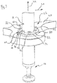
- FIG. 3 is an area around a connecting device 22 isolated and shown in detail.
- An axial direction 24 is represented by an arrow with the corresponding reference numeral, just as a radial direction 26.
- the axial direction 24 and the radial direction refer to those in the FIG. 3 illustrated rod elements 12.
- the connecting device 22 from FIG. 3 includes an in FIG. 5 in section shown clamping element 30, which in the illustration of FIG. 3 is disposed in an opening 17 of the support member 20.
- the connecting device 22 further comprises a plurality of clamping elements 32, which are designed as clamping screws 33.
- the connecting device 22 comprises a sleeve element 34, which is designed in the manner of a flange and has an outer flange section 36. An outer flange portion 36 abuts axially against the carrier element 20 with a contact surface 38.
- the sleeve member 34 forms a clamping sleeve in the opening 17 of the support member 20th
- Das Cuff member 34 has a clamping groove 40 which in FIG. 3 is clearly visible.
- FIG. 5 is the section from the Figures 3 and 4 shown during assembly of the connecting device.
- the clamping element 30 has a clamping joint 40.
- the clamping element 30 has in the in FIG. 5 also shown embodiment five blind holes 52, each carrying a hole-side thread 44.
- the structure of the sleeve member 34 is also clearly visible.
- the sleeve member also includes a sleeve forming radially inner portion 48.
- the clamping groove 40 extends through both the outer flange portion 36 as well as the sleeve forming radially inner portion 48th
- the clamping element 30 When mounting the connecting device, the clamping element 30 is guided over the rod member 12 and through the opening 17 therethrough. Thereafter, the sleeve member 34 is guided over the rod member 12 and then the support member 20 is brought exactly to the desired position, wherein the support member 20 is applied to the abutment surface 38 of the outer flange portion 36.
- the clamping elements 32 are guided through the respective through openings 46 in the sleeve member 34 and then the clamping member 30 positioned so that the clamping elements 32 are inserted into the blind holes 42 of the clamping member 30 and there with a respective screw thread 50 in the hole-side threads 44 of the blind holes 42 engage ,
- a gap 54 is formed, which is present annular and circumferentially continuous.
- the gap 54 tapers in a wedge shape in the axial direction 24 toward the outer flange section 36 of the sleeve element 34.
- the clamping element 30 is received in the gap 54.
- the clamping element 30 is connected to an outer surface 56, which corresponds to the lateral surface of a cylinder, on the concentric to the outer surface 56, the gap 54 delimiting carrier element-side clamping surface 52 at.
- the clamping element 30 With an inner surface 58, which corresponds to the lateral surface of a truncated cone, the clamping element 30 is located on a clamping surface 60 which extends concentrically to the inner surface 58 and delimits the gap 54.
- the gap 54 tapers at an angle w, which in the illustration of FIG. 6 to exaggerate the operation is exaggerated.
- Angle w is in the context of the invention preferably 2 ° to 10 °, preferably 3 ° to 8 °, in particular 3.5 ° to 6 °, in particular 4 ° to 5 °, compared to the axial direction 24. This is an advantageous ratio of movement of the clamping element 30 in the gap 54 inside and jamming of the sleeve member 34 on the other hand achieved.
- the taper of the gap is completely caused by the course of the cuff-element-side clamping surface 60 and the inner surface 58 of the clamping element 30 at an angle W, since the carrier element-side clamping surface 52 and the outer surface 56 of the clamping element 30 with respect to the axial direction 24 is not angled. Subsequently, the assembly of the support member 20 via the connecting device 22 based on the FIG. 6 described in more detail. In the in FIG.
- the clamping member 30 slides with its outer surface 56 along the concentric with the outer surface 56 extending support member side clamping surface 52 and with its inner surface 58 along the cuff member clamping surface 60, which is also concentric with the inner surface 58. Since the gap 54 tapers towards the flange portion 36, the gap 54 is widened by the pulling in of the clamping element and thus the contact surface of the sleeve element 34 against the fastening portion 16 of the rod element 12 pressed, and at the same time the outer surface 56 of the clamping member is pressed against the carrier-element-side clamping surface 52, which limits the gap 54.
Landscapes
- Engineering & Computer Science (AREA)
- General Engineering & Computer Science (AREA)
- Mechanical Engineering (AREA)
- Clamps And Clips (AREA)
- Mutual Connection Of Rods And Tubes (AREA)
- Absorbent Articles And Supports Therefor (AREA)
Priority Applications (2)
| Application Number | Priority Date | Filing Date | Title |
|---|---|---|---|
| EP18198752.0A EP3441225B1 (fr) | 2016-05-30 | 2017-05-05 | Bâti de machine à imprimer au tampon |
| DK18198752.0T DK3441225T3 (da) | 2016-05-30 | 2017-05-05 | Maskinramme |
Applications Claiming Priority (1)
| Application Number | Priority Date | Filing Date | Title |
|---|---|---|---|
| DE102016109929.5A DE102016109929B3 (de) | 2016-05-30 | 2016-05-30 | Tampondruckmaschinengestell |
Related Child Applications (2)
| Application Number | Title | Priority Date | Filing Date |
|---|---|---|---|
| EP18198752.0A Division-Into EP3441225B1 (fr) | 2016-05-30 | 2017-05-05 | Bâti de machine à imprimer au tampon |
| EP18198752.0A Division EP3441225B1 (fr) | 2016-05-30 | 2017-05-05 | Bâti de machine à imprimer au tampon |
Publications (3)
| Publication Number | Publication Date |
|---|---|
| EP3251847A2 true EP3251847A2 (fr) | 2017-12-06 |
| EP3251847A3 EP3251847A3 (fr) | 2018-02-14 |
| EP3251847B1 EP3251847B1 (fr) | 2019-03-20 |
Family
ID=58672457
Family Applications (2)
| Application Number | Title | Priority Date | Filing Date |
|---|---|---|---|
| EP18198752.0A Active EP3441225B1 (fr) | 2016-05-30 | 2017-05-05 | Bâti de machine à imprimer au tampon |
| EP17169784.0A Active EP3251847B1 (fr) | 2016-05-30 | 2017-05-05 | Bâti de machine à imprimer au tampon |
Family Applications Before (1)
| Application Number | Title | Priority Date | Filing Date |
|---|---|---|---|
| EP18198752.0A Active EP3441225B1 (fr) | 2016-05-30 | 2017-05-05 | Bâti de machine à imprimer au tampon |
Country Status (3)
| Country | Link |
|---|---|
| EP (2) | EP3441225B1 (fr) |
| DE (1) | DE102016109929B3 (fr) |
| DK (1) | DK3441225T3 (fr) |
Family Cites Families (4)
| Publication number | Priority date | Publication date | Assignee | Title |
|---|---|---|---|---|
| GB736312A (en) * | 1951-08-04 | 1955-09-07 | Guy Leslie Murray | Means for printing or decorating ceramic ware |
| DE8419344U1 (de) * | 1984-06-28 | 1984-08-09 | KEUCO Paul Keune GmbH & Co KG, 5870 Hemer | Rohrdübel |
| DE3926146A1 (de) * | 1989-08-08 | 1991-02-21 | Werner Goekeler | Vorrichtung |
| DE29605123U1 (de) * | 1996-03-20 | 1997-07-17 | Morlock, Rudi, 72270 Baiersbronn | Tampondruckmaschine |
-
2016
- 2016-05-30 DE DE102016109929.5A patent/DE102016109929B3/de not_active Expired - Fee Related
-
2017
- 2017-05-05 DK DK18198752.0T patent/DK3441225T3/da active
- 2017-05-05 EP EP18198752.0A patent/EP3441225B1/fr active Active
- 2017-05-05 EP EP17169784.0A patent/EP3251847B1/fr active Active
Non-Patent Citations (1)
| Title |
|---|
| None |
Also Published As
| Publication number | Publication date |
|---|---|
| DK3441225T3 (da) | 2020-01-06 |
| EP3251847A3 (fr) | 2018-02-14 |
| EP3251847B1 (fr) | 2019-03-20 |
| DE102016109929B3 (de) | 2017-09-07 |
| EP3441225A1 (fr) | 2019-02-13 |
| EP3441225B1 (fr) | 2019-09-25 |
Similar Documents
| Publication | Publication Date | Title |
|---|---|---|
| WO2008092752A1 (fr) | Outil d'alésage équilibré comprenant un mécanisme de serrage | |
| DE102009022191B3 (de) | Fadenführeranordnung einer Kettenwirkmaschine | |
| DE2544498C3 (de) | Gewindering | |
| DE3013874C2 (de) | Spannsatz in Doppelausführung zur Nabenbefestigung | |
| DE1085721B (de) | Klemmverbindung | |
| DE2256306A1 (de) | Spannhuelsenanordnung | |
| WO2018224237A1 (fr) | Moyens de serrage intérieur à bague segmentée de serrage bloquée | |
| DE60038654T2 (de) | Klemmhalterung für Stütz- und Verbindungselemente | |
| EP3500786A1 (fr) | Griffe de fixation | |
| EP0846908A1 (fr) | Connection entre tube et composant. | |
| DE102013103913A1 (de) | Spanner | |
| EP3251847B1 (fr) | Bâti de machine à imprimer au tampon | |
| DE1191998B (de) | Sicherungsmutter | |
| DE1961980C3 (de) | Nabenbefestigung | |
| DE2604669A1 (de) | Kupplung | |
| DE1625621B2 (de) | Gleitlager | |
| DE202016102853U1 (de) | Tampondruckmaschinengestell und Maschinengestell | |
| EP3839318B1 (fr) | Élément à vis et système | |
| DE102012110338A1 (de) | Schraubverbindungsanordnung | |
| DE1199544B (de) | Befestigungsvorrichtung, insbesondere zum Befestigen von Verblendplatten | |
| DE102017104546A1 (de) | Laufklemmung für eine Schusswaffe | |
| DE202007005772U1 (de) | Spannvorrichtungsbaugruppe für eine Maschine | |
| DE102016005487B4 (de) | Montageeinrichtung zum Montieren einer Armatur | |
| DE102019123996A1 (de) | Verbindungsanordnung | |
| DE102012000613A1 (de) | Kugelsperrbolzen |
Legal Events
| Date | Code | Title | Description |
|---|---|---|---|
| PUAI | Public reference made under article 153(3) epc to a published international application that has entered the european phase |
Free format text: ORIGINAL CODE: 0009012 |
|
| STAA | Information on the status of an ep patent application or granted ep patent |
Free format text: STATUS: THE APPLICATION HAS BEEN PUBLISHED |
|
| AK | Designated contracting states |
Kind code of ref document: A2 Designated state(s): AL AT BE BG CH CY CZ DE DK EE ES FI FR GB GR HR HU IE IS IT LI LT LU LV MC MK MT NL NO PL PT RO RS SE SI SK SM TR |
|
| AX | Request for extension of the european patent |
Extension state: BA ME |
|
| PUAL | Search report despatched |
Free format text: ORIGINAL CODE: 0009013 |
|
| AK | Designated contracting states |
Kind code of ref document: A3 Designated state(s): AL AT BE BG CH CY CZ DE DK EE ES FI FR GB GR HR HU IE IS IT LI LT LU LV MC MK MT NL NO PL PT RO RS SE SI SK SM TR |
|
| AX | Request for extension of the european patent |
Extension state: BA ME |
|
| RIC1 | Information provided on ipc code assigned before grant |
Ipc: B41F 13/00 20060101ALI20180109BHEP Ipc: F16M 7/00 20060101ALI20180109BHEP Ipc: B41F 17/00 20060101AFI20180109BHEP |
|
| STAA | Information on the status of an ep patent application or granted ep patent |
Free format text: STATUS: REQUEST FOR EXAMINATION WAS MADE |
|
| 17P | Request for examination filed |
Effective date: 20180703 |
|
| RBV | Designated contracting states (corrected) |
Designated state(s): AL AT BE BG CH CY CZ DE DK EE ES FI FR GB GR HR HU IE IS IT LI LT LU LV MC MK MT NL NO PL PT RO RS SE SI SK SM TR |
|
| GRAP | Despatch of communication of intention to grant a patent |
Free format text: ORIGINAL CODE: EPIDOSNIGR1 |
|
| STAA | Information on the status of an ep patent application or granted ep patent |
Free format text: STATUS: GRANT OF PATENT IS INTENDED |
|
| INTG | Intention to grant announced |
Effective date: 20180925 |
|
| GRAS | Grant fee paid |
Free format text: ORIGINAL CODE: EPIDOSNIGR3 |
|
| GRAA | (expected) grant |
Free format text: ORIGINAL CODE: 0009210 |
|
| STAA | Information on the status of an ep patent application or granted ep patent |
Free format text: STATUS: THE PATENT HAS BEEN GRANTED |
|
| AK | Designated contracting states |
Kind code of ref document: B1 Designated state(s): AL AT BE BG CH CY CZ DE DK EE ES FI FR GB GR HR HU IE IS IT LI LT LU LV MC MK MT NL NO PL PT RO RS SE SI SK SM TR |
|
| REG | Reference to a national code |
Ref country code: GB Ref legal event code: FG4D Free format text: NOT ENGLISH |
|
| REG | Reference to a national code |
Ref country code: CH Ref legal event code: EP |
|
| REG | Reference to a national code |
Ref country code: DE Ref legal event code: R096 Ref document number: 502017000946 Country of ref document: DE |
|
| REG | Reference to a national code |
Ref country code: AT Ref legal event code: REF Ref document number: 1110124 Country of ref document: AT Kind code of ref document: T Effective date: 20190415 |
|
| REG | Reference to a national code |
Ref country code: IE Ref legal event code: FG4D Free format text: LANGUAGE OF EP DOCUMENT: GERMAN |
|
| REG | Reference to a national code |
Ref country code: CH Ref legal event code: NV Representative=s name: DREISS PATENTANWAELTE PARTG MBB, DE |
|
| REG | Reference to a national code |
Ref country code: NL Ref legal event code: FP |
|
| PG25 | Lapsed in a contracting state [announced via postgrant information from national office to epo] |
Ref country code: SE Free format text: LAPSE BECAUSE OF FAILURE TO SUBMIT A TRANSLATION OF THE DESCRIPTION OR TO PAY THE FEE WITHIN THE PRESCRIBED TIME-LIMIT Effective date: 20190320 Ref country code: LT Free format text: LAPSE BECAUSE OF FAILURE TO SUBMIT A TRANSLATION OF THE DESCRIPTION OR TO PAY THE FEE WITHIN THE PRESCRIBED TIME-LIMIT Effective date: 20190320 Ref country code: FI Free format text: LAPSE BECAUSE OF FAILURE TO SUBMIT A TRANSLATION OF THE DESCRIPTION OR TO PAY THE FEE WITHIN THE PRESCRIBED TIME-LIMIT Effective date: 20190320 Ref country code: NO Free format text: LAPSE BECAUSE OF FAILURE TO SUBMIT A TRANSLATION OF THE DESCRIPTION OR TO PAY THE FEE WITHIN THE PRESCRIBED TIME-LIMIT Effective date: 20190620 |
|
| REG | Reference to a national code |
Ref country code: LT Ref legal event code: MG4D |
|
| PG25 | Lapsed in a contracting state [announced via postgrant information from national office to epo] |
Ref country code: BG Free format text: LAPSE BECAUSE OF FAILURE TO SUBMIT A TRANSLATION OF THE DESCRIPTION OR TO PAY THE FEE WITHIN THE PRESCRIBED TIME-LIMIT Effective date: 20190620 Ref country code: GR Free format text: LAPSE BECAUSE OF FAILURE TO SUBMIT A TRANSLATION OF THE DESCRIPTION OR TO PAY THE FEE WITHIN THE PRESCRIBED TIME-LIMIT Effective date: 20190621 Ref country code: RS Free format text: LAPSE BECAUSE OF FAILURE TO SUBMIT A TRANSLATION OF THE DESCRIPTION OR TO PAY THE FEE WITHIN THE PRESCRIBED TIME-LIMIT Effective date: 20190320 Ref country code: LV Free format text: LAPSE BECAUSE OF FAILURE TO SUBMIT A TRANSLATION OF THE DESCRIPTION OR TO PAY THE FEE WITHIN THE PRESCRIBED TIME-LIMIT Effective date: 20190320 Ref country code: HR Free format text: LAPSE BECAUSE OF FAILURE TO SUBMIT A TRANSLATION OF THE DESCRIPTION OR TO PAY THE FEE WITHIN THE PRESCRIBED TIME-LIMIT Effective date: 20190320 |
|
| PG25 | Lapsed in a contracting state [announced via postgrant information from national office to epo] |
Ref country code: RO Free format text: LAPSE BECAUSE OF FAILURE TO SUBMIT A TRANSLATION OF THE DESCRIPTION OR TO PAY THE FEE WITHIN THE PRESCRIBED TIME-LIMIT Effective date: 20190320 Ref country code: PT Free format text: LAPSE BECAUSE OF FAILURE TO SUBMIT A TRANSLATION OF THE DESCRIPTION OR TO PAY THE FEE WITHIN THE PRESCRIBED TIME-LIMIT Effective date: 20190720 Ref country code: AL Free format text: LAPSE BECAUSE OF FAILURE TO SUBMIT A TRANSLATION OF THE DESCRIPTION OR TO PAY THE FEE WITHIN THE PRESCRIBED TIME-LIMIT Effective date: 20190320 Ref country code: SK Free format text: LAPSE BECAUSE OF FAILURE TO SUBMIT A TRANSLATION OF THE DESCRIPTION OR TO PAY THE FEE WITHIN THE PRESCRIBED TIME-LIMIT Effective date: 20190320 Ref country code: ES Free format text: LAPSE BECAUSE OF FAILURE TO SUBMIT A TRANSLATION OF THE DESCRIPTION OR TO PAY THE FEE WITHIN THE PRESCRIBED TIME-LIMIT Effective date: 20190320 Ref country code: EE Free format text: LAPSE BECAUSE OF FAILURE TO SUBMIT A TRANSLATION OF THE DESCRIPTION OR TO PAY THE FEE WITHIN THE PRESCRIBED TIME-LIMIT Effective date: 20190320 Ref country code: CZ Free format text: LAPSE BECAUSE OF FAILURE TO SUBMIT A TRANSLATION OF THE DESCRIPTION OR TO PAY THE FEE WITHIN THE PRESCRIBED TIME-LIMIT Effective date: 20190320 |
|
| PG25 | Lapsed in a contracting state [announced via postgrant information from national office to epo] |
Ref country code: SM Free format text: LAPSE BECAUSE OF FAILURE TO SUBMIT A TRANSLATION OF THE DESCRIPTION OR TO PAY THE FEE WITHIN THE PRESCRIBED TIME-LIMIT Effective date: 20190320 Ref country code: PL Free format text: LAPSE BECAUSE OF FAILURE TO SUBMIT A TRANSLATION OF THE DESCRIPTION OR TO PAY THE FEE WITHIN THE PRESCRIBED TIME-LIMIT Effective date: 20190320 |
|
| PG25 | Lapsed in a contracting state [announced via postgrant information from national office to epo] |
Ref country code: IS Free format text: LAPSE BECAUSE OF FAILURE TO SUBMIT A TRANSLATION OF THE DESCRIPTION OR TO PAY THE FEE WITHIN THE PRESCRIBED TIME-LIMIT Effective date: 20190720 |
|
| REG | Reference to a national code |
Ref country code: DE Ref legal event code: R097 Ref document number: 502017000946 Country of ref document: DE |
|
| PLBE | No opposition filed within time limit |
Free format text: ORIGINAL CODE: 0009261 |
|
| STAA | Information on the status of an ep patent application or granted ep patent |
Free format text: STATUS: NO OPPOSITION FILED WITHIN TIME LIMIT |
|
| PG25 | Lapsed in a contracting state [announced via postgrant information from national office to epo] |
Ref country code: DK Free format text: LAPSE BECAUSE OF FAILURE TO SUBMIT A TRANSLATION OF THE DESCRIPTION OR TO PAY THE FEE WITHIN THE PRESCRIBED TIME-LIMIT Effective date: 20190320 Ref country code: MC Free format text: LAPSE BECAUSE OF FAILURE TO SUBMIT A TRANSLATION OF THE DESCRIPTION OR TO PAY THE FEE WITHIN THE PRESCRIBED TIME-LIMIT Effective date: 20190320 |
|
| REG | Reference to a national code |
Ref country code: BE Ref legal event code: MM Effective date: 20190531 |
|
| 26N | No opposition filed |
Effective date: 20200102 |
|
| PG25 | Lapsed in a contracting state [announced via postgrant information from national office to epo] |
Ref country code: LU Free format text: LAPSE BECAUSE OF NON-PAYMENT OF DUE FEES Effective date: 20190505 Ref country code: SI Free format text: LAPSE BECAUSE OF FAILURE TO SUBMIT A TRANSLATION OF THE DESCRIPTION OR TO PAY THE FEE WITHIN THE PRESCRIBED TIME-LIMIT Effective date: 20190320 |
|
| PG25 | Lapsed in a contracting state [announced via postgrant information from national office to epo] |
Ref country code: TR Free format text: LAPSE BECAUSE OF FAILURE TO SUBMIT A TRANSLATION OF THE DESCRIPTION OR TO PAY THE FEE WITHIN THE PRESCRIBED TIME-LIMIT Effective date: 20190320 |
|
| PG25 | Lapsed in a contracting state [announced via postgrant information from national office to epo] |
Ref country code: IE Free format text: LAPSE BECAUSE OF NON-PAYMENT OF DUE FEES Effective date: 20190505 |
|
| PG25 | Lapsed in a contracting state [announced via postgrant information from national office to epo] |
Ref country code: BE Free format text: LAPSE BECAUSE OF NON-PAYMENT OF DUE FEES Effective date: 20190531 |
|
| PG25 | Lapsed in a contracting state [announced via postgrant information from national office to epo] |
Ref country code: CY Free format text: LAPSE BECAUSE OF FAILURE TO SUBMIT A TRANSLATION OF THE DESCRIPTION OR TO PAY THE FEE WITHIN THE PRESCRIBED TIME-LIMIT Effective date: 20190320 |
|
| PG25 | Lapsed in a contracting state [announced via postgrant information from national office to epo] |
Ref country code: HU Free format text: LAPSE BECAUSE OF FAILURE TO SUBMIT A TRANSLATION OF THE DESCRIPTION OR TO PAY THE FEE WITHIN THE PRESCRIBED TIME-LIMIT; INVALID AB INITIO Effective date: 20170505 Ref country code: MT Free format text: LAPSE BECAUSE OF FAILURE TO SUBMIT A TRANSLATION OF THE DESCRIPTION OR TO PAY THE FEE WITHIN THE PRESCRIBED TIME-LIMIT Effective date: 20190320 |
|
| PG25 | Lapsed in a contracting state [announced via postgrant information from national office to epo] |
Ref country code: MK Free format text: LAPSE BECAUSE OF FAILURE TO SUBMIT A TRANSLATION OF THE DESCRIPTION OR TO PAY THE FEE WITHIN THE PRESCRIBED TIME-LIMIT Effective date: 20190320 |
|
| P01 | Opt-out of the competence of the unified patent court (upc) registered |
Effective date: 20230509 |
|
| PGFP | Annual fee paid to national office [announced via postgrant information from national office to epo] |
Ref country code: NL Payment date: 20250522 Year of fee payment: 9 |
|
| PGFP | Annual fee paid to national office [announced via postgrant information from national office to epo] |
Ref country code: GB Payment date: 20250519 Year of fee payment: 9 |
|
| PGFP | Annual fee paid to national office [announced via postgrant information from national office to epo] |
Ref country code: IT Payment date: 20250530 Year of fee payment: 9 |
|
| PGFP | Annual fee paid to national office [announced via postgrant information from national office to epo] |
Ref country code: FR Payment date: 20250521 Year of fee payment: 9 |
|
| PGFP | Annual fee paid to national office [announced via postgrant information from national office to epo] |
Ref country code: CH Payment date: 20250601 Year of fee payment: 9 |
|
| PGFP | Annual fee paid to national office [announced via postgrant information from national office to epo] |
Ref country code: AT Payment date: 20250519 Year of fee payment: 9 |
|
| PGFP | Annual fee paid to national office [announced via postgrant information from national office to epo] |
Ref country code: DE Payment date: 20250721 Year of fee payment: 9 |