EP3251955A1 - Verfahren und hilfsvorrichtung zur steuerung eines luftfahrzeugs, und luftfahrzeug - Google Patents
Verfahren und hilfsvorrichtung zur steuerung eines luftfahrzeugs, und luftfahrzeug Download PDFInfo
- Publication number
- EP3251955A1 EP3251955A1 EP17165759.6A EP17165759A EP3251955A1 EP 3251955 A1 EP3251955 A1 EP 3251955A1 EP 17165759 A EP17165759 A EP 17165759A EP 3251955 A1 EP3251955 A1 EP 3251955A1
- Authority
- EP
- European Patent Office
- Prior art keywords
- margin
- limit
- collective pitch
- collective
- speed
- Prior art date
- Legal status (The legal status is an assumption and is not a legal conclusion. Google has not performed a legal analysis and makes no representation as to the accuracy of the status listed.)
- Granted
Links
Images

Classifications
-
- B—PERFORMING OPERATIONS; TRANSPORTING
- B64—AIRCRAFT; AVIATION; COSMONAUTICS
- B64D—EQUIPMENT FOR FITTING IN OR TO AIRCRAFT; FLIGHT SUITS; PARACHUTES; ARRANGEMENT OR MOUNTING OF POWER PLANTS OR PROPULSION TRANSMISSIONS IN AIRCRAFT
- B64D43/00—Arrangements or adaptations of instruments
-
- B—PERFORMING OPERATIONS; TRANSPORTING
- B64—AIRCRAFT; AVIATION; COSMONAUTICS
- B64C—AEROPLANES; HELICOPTERS
- B64C27/00—Rotorcraft; Rotors peculiar thereto
- B64C27/006—Safety devices
-
- B—PERFORMING OPERATIONS; TRANSPORTING
- B64—AIRCRAFT; AVIATION; COSMONAUTICS
- B64C—AEROPLANES; HELICOPTERS
- B64C27/00—Rotorcraft; Rotors peculiar thereto
- B64C27/54—Mechanisms for controlling blade adjustment or movement relative to rotor head, e.g. lag-lead movement
-
- B—PERFORMING OPERATIONS; TRANSPORTING
- B64—AIRCRAFT; AVIATION; COSMONAUTICS
- B64C—AEROPLANES; HELICOPTERS
- B64C27/00—Rotorcraft; Rotors peculiar thereto
- B64C27/04—Helicopters
-
- F—MECHANICAL ENGINEERING; LIGHTING; HEATING; WEAPONS; BLASTING
- F05—INDEXING SCHEMES RELATING TO ENGINES OR PUMPS IN VARIOUS SUBCLASSES OF CLASSES F01-F04
- F05D—INDEXING SCHEME FOR ASPECTS RELATING TO NON-POSITIVE-DISPLACEMENT MACHINES OR ENGINES, GAS-TURBINES OR JET-PROPULSION PLANTS
- F05D2220/00—Application
- F05D2220/30—Application in turbines
- F05D2220/32—Application in turbines in gas turbines
- F05D2220/329—Application in turbines in gas turbines in helicopters
Definitions
- the present invention relates to a method and a device for assisting the piloting of an aircraft, as well as an aircraft.
- the aircraft is a rotorcraft equipped with a rotor participating at least in the lift or even the propulsion of this rotorcraft.
- the rotorcraft are generally provided with a power plant comprising at least one engine, such as a turbine engine type turbine engine free turbine.
- the power is then taken from a low pressure stage of each free turbine which rotates for example between 20 000 and 50 000 revolutions per minute.
- the power plant includes a speed reduction gearbox for connecting the free turbines to the main rotor since the rotational speed of this rotor is substantially between 200 and 400 revolutions per minute.
- a gearbox is referred to as a "main power gearbox”.
- a motorist establishes, by calculation or by tests, the available power curves of an engine according to the altitude and the outside temperature.
- the engine determines the limitations of each engine to obtain PMC power, PMD, PMT, PSU, PMU, PIU corresponding to each aforementioned regime and an acceptable life.
- these limits are generally monitored by means of three monitoring parameters: the speed of rotation of the gas turbine engine, the engine torque and the gas temperature at the inlet of the turbine's low-pressure free turbine. respectively denominated Ng, Cm and T45 by the skilled person.
- the turbine engine comprises a high pressure turbine stage, the temperature of the gases at the inlet of the high pressure turbine called TET can be used. This temperature of the gases at the inlet of the high pressure turbine TET is difficult to measure and therefore sometimes calculated from the temperature of the gases at the inlet of the free turbine T45.
- the engine manufacturer sets limits for each parameter monitoring. These limits may vary according to the external conditions, namely the external pressure P0 and the external temperature T0 of the air outside the aircraft.
- the third limits can be measured by analogy using the torque exerted at the main gearbox, at the input of this gearbox main and / or its main rotor driving mast for example.
- the manufacturer further determines fourth limits TQ lim PMD , TQ lim PMC , and TQ lim PMT corresponding to the torque exerted on the main gearbox, for example at its driving mast. of the main rotor, when the engine develops the maximum power at takeoff as well as the maximum continuous power and the maximum power transient.
- the pilot of a rotorcraft must then control his aircraft taking into consideration the appropriate limits in order to respect the instructions of the engine manufacturer and protect the dynamic sets of the helicopter.
- a rotorcraft has many instruments on the dashboard, instruments that are for the most part representative of the operation of the rotorcraft power plant.
- the rotorcraft may include an indicator showing the current value of the monitoring parameter and its limit. Such an indicator is referred to as the "individual indicator" convenience.
- an instrument is used to display only the most restrictive monitoring parameter information.
- the document FR2749545 relates to a control indicator presenting information relating to the monitoring parameter of a turbine engine closest to its limit value.
- the information relating to the limitations to be respected are thus grouped together in a single display, allowing, on the one hand, to summarize and present only the result of this summary in order to simplify the task of the pilot and, on the other hand , to save space on the dashboard.
- a "limiting parameter” is thus obtained from among said turbine engine monitoring parameters whose current value is closest to the limit value for said parameter.
- such an indicator is known under the name “instrument of first limitation” corresponding to the acronym "IPL”.
- the expression “First Limitation Instrument” corresponding to the acronym "FLI” is sometimes used for this purpose in English.
- the document FR 2,756,256 suggests to present on a display screen the power margin available for the power plant before reaching a limit on a graduated scale in collective pitch equivalent of the main rotor blades, the scale scrolling past a representative index of the pitch collective current of said blades.
- the index is vis-à-vis a first graduation, the limit of the parameter limiting to a given power being vis-à-vis a second graduation greater than the first graduation.
- the pilot then visualizes the collective pitch margin at his disposal before reaching said given power.
- each margin of a monitoring parameter is converted into a power margin.
- the lowest power margin is then selected and transformed into a collective margin.
- the sum of this margin of collective step and the current collective step makes it possible to obtain a limit of collective step to be displayed.
- Such an indicator is very effective, especially during stabilized operation phases.
- the rotorcraft usually retains the usual individual indicators in addition to the first limitation indicator to allow monitoring of each single monitoring parameter.
- the object of the present invention is therefore to propose a method and a device for assisting alternative driving with a view to achieving an optimized precision.
- the invention therefore relates to a method of assisting the piloting of an aircraft, the aircraft being provided with a power plant comprising at least one engine and a main rotor participating at least partially in the lift and / or the propulsion of this aircraft, each motor being regulated by a control means according to a setpoint, the powerplant being monitored by determining a value of a plurality of predetermined monitoring parameters, said aircraft being a rotorcraft.
- the monitoring parameters may include the speed of rotation of the gas turbine engine, the engine torque of the turbine engine and the temperature of the gas at the inlet of the free turbine low pressure turbine engine. If the turbine engine comprises a high pressure turbine stage, the temperature of the gases at the inlet of the high pressure turbine called TET can be used.
- the power plant further comprises a power transmission gearbox connected to at least one engine and the main rotor, the monitoring parameters may include a torque exerted in this power transmission.
- the collective pitch of the main rotor blades can for example be controlled by a control means operable by a pilot, such as a lever for example.
- the control means can be coupled to a law of effort.
- the position of this control means makes it possible, for example, to evaluate the collective pitch of the blades of the main rotor.
- teaching the document FR 2,756,256 can be used to determine the limiting power margin and determine the collective pitch limit from the collective pitch margin.
- the collective pitch margin is determined by applying an algorithm lowering the collective pitch margin with respect to a real collective pitch margin at the operating regime proportional to the limiting power margin when the limiting power margin is non-zero for anticipate exceeding said setpoint induced by a regulating means of said motor, said collective pitch margin being zero when the limiting power margin is zero.
- a pilot can quickly move the control means of the collective pitch of the main rotor blades to use all of the displayed collective pitch margin.
- the regulating means consequently regulates the flow of fuel transmitted to the engine.
- the engine may exceed one of its limits for a short time before reaching the required power.
- Such a phenomenon is sometimes referred to as "overshoot" in the English language.
- the invention tends to avoid such transient overrun by lowering the displayed collective pitch margin, compared to the actual collective pitch margin that is actually available, at least as long as the limiting power margin is not zero.
- collector margin refers to the collective margin used to determine the posted collective limit.
- real collective margin refers to the actual collective margin available.
- the limiting power margin is transformed into a lower power margin that is transformed into the collective margin.
- the limiting power margin is transformed into a real collective pitch margin, the actual collective pitch margin being reduced to obtain the collective pitch margin.
- the limiting power margin is directly transformed into the collective margin.
- the collective pitch margin is determined by applying a recursive algorithm using a main relationship providing at each current computation time the collective pitch margin as a function of the quotient of the limiting power margin and a denominator, the denominator being equal to the product of a first term and a second term, the first term being a function of the current collective pitch of said blades at the instant of current calculation and the collective pitch limit at the preceding calculation time preceding said current calculation time, said second term being a function of at least one predetermined coefficient lowering said power margin of the power plant.
- ⁇ ⁇ ⁇ W lim AT 1 ⁇ limit not - 1 ⁇ not * AT 2 B
- ⁇ ⁇ represents the collective pitch margin
- ⁇ Wlim represents the limiting power margin
- AT 1 ⁇ limit not - 1 ⁇ not represents the first term function of the current collective pitch ⁇ n at the current calculation instant and the collective pitch limit ⁇ limit not - 1 at the time of calculation performed just before said current calculation time
- A2 ( B ) represents the second term function of at least a predetermined coefficient B lowering said power margin of the power plant.
- This algorithm is therefore based on a factored expression of the collective pitch margin including the limiting factor power margin.
- This algorithm aims to induce that a zero collective margin margin induces a zero power margin and vice versa.
- the collective pitch margin is added to the current collective pitch to lead to a collective step limit that is displayed on a screen for example.
- the calculated collective margin of margin therefore depends on a coefficient that tends to reduce this collective margin.
- the coefficient B is determined by tests and chosen in such a way as to ensure a calculation of the reduced collective pitch margins so that, when maneuvering the crew, the limitations of the powerplant are always respected.
- the optimized precision of the collective pitch limit finally obtained may tend to make the individual indicators of the prior art useless, if necessary by applying variants described hereinafter.
- the method can take into account the variation of the rotational speed of the main rotor through a power penalty applied to the limiting power margin, the influence of an auxiliary rotor or the variation of the speed of rotation. progress of the aircraft.
- the method can optionally be implemented on an aircraft tending to use the technology called "part time display" in English.
- the individual indicators need not necessarily be permanently visible.
- the information provided by these individual indicators can then appear on request only on a screen to provide various data, not permanently.
- this method can be used to determine a collective pitch limit for various engine operating regimes, with at least two distinct collective pitch limits be displayed simultaneously.
- the teaching of the document FR 2,756,256 can be used.
- the method may further include one or more of the following features.
- the individual power margins or the limiting margin are provided by the engine control means.
- Such a regulating means is sometimes known by the acronym "FADEC”.
- A1 represents said first term
- " ⁇ limit not - 1 " represents the collective step limit at the preceding computation time preceding the current computation time
- ⁇ n represents said current collective pitch
- " ⁇ 0 " represents a constant relative to a collective reference step
- "+” represents the sign of the addition
- "-” represents the sign of the subtraction
- "*" represents the sign of the multiplication.
- the constant ⁇ 0 relative to a collective pitch of reference can be invariable and determined by tests so that the recursive algorithm converges.
- the parameter Nr relating to the rotational speed of the main rotor may be a fixed constant.
- the main rotor may be associated with a nominal speed of rotation, this rotor must tend to rotate at this speed of rotation. nominal rotation.
- the parameter Nr is equal to the value of the nominal rotation speed.
- the rotor may be associated with a nominal rotational speed which varies according to the flight phase. Therefore, the parameter Nr can be equal to the value of the nominal rotation speed corresponding to the current flight phase.
- the method of the invention provides for measuring a rotational speed at least proportional to the speed of rotation of the rotor.
- the parameter Nr is equal to each calculation instant to the measured value of the rotational speed of the main rotor, or to the product of a proportionality constant and the measured value of the rotational speed of an organ. generating directly or indirectly the rotation of the main rotor.
- the density " ⁇ " can be corrected in flight according to known relationships as a function of the external pressure and the outside temperature of the air present outside the aircraft.
- W limit ⁇ ⁇ Nr 3 AT + B ⁇ ⁇ lim - ⁇ 0 2
- W limit " represents the limit power
- ⁇ represents the density of the air
- Nr represents a parameter relative to the rotational speed of the main rotor
- ⁇ lim represents the limit collective pitch
- ⁇ 0 Is the constant relative to a collective reference step.
- said coefficient B may be a dimensionless variable which varies as a function of the speed of advance of the aircraft.
- the coefficient B may vary according to a forward speed of the aircraft divided by a reference speed.
- the speed of advancement can be the so-called "Indicated Air Speed" speed in the English language and known by the acronym IAS.
- the coefficient is equal to 6.25 with a forward speed of 150 knots, 7 with a forward speed of 70 knots and 8.2 with a forward speed of 40 knots.
- the limiting power margin is reduced by a predetermined percentage if the rotational speed of the main rotor decreases at a predetermined speed for a predetermined time.
- the method according to the invention provides for transforming a power margin into a collective pitch margin by using for example a recursive algorithm.
- This recursive algorithm gives good results during stabilized flight phases, even during dynamic flight phases with a well-regulated engine.
- the rotational speed of the main rotor may decrease.
- the motor accelerates to maintain the rotational speed of the main rotor equal to a setpoint.
- a first order filter can be applied to the rotational speed of the main rotor to calculate its variation.
- the speed predetermined amount corresponds to 4% of a reference speed per second, the predetermined time being equal to 0.5 seconds.
- This additional feature tends to improve the accuracy of the collective pitch limit.
- the percentage applied to reduce the limiting power margin may decrease from a maximum to a zero value over a predetermined period.
- the penalty applied is equivalent to a reduction of 25% of the limiting power margin, and is applied degressively or even linearly to be zero after 2 seconds.
- the method may comprise a gel step during which the collective pitch limit is maintained equal to the value of this collective pitch limit reached before said phase of flight. agressive.
- the collective pitch limit may be falsely maximized because of the reaction time of the engine following a given command to control the pitch of the main rotor blades.
- this additional feature proposes to freeze the value of the collective step limit during the dynamic flight phase.
- this relationship may be less precise.
- the collective pitch limit is frozen during the transient phases.
- a transient phase is a very aggressive dynamic flight phase when the collective pitch of the main rotor blades varies at a speed greater than the high speed variation threshold.
- a threshold of high speed variation is for example equal to 1.6 ° per second.
- the variation of the collective pitch of the main rotor can be determined by applying a first order filter.
- a transient phase is an aggressive dynamic flight phase when the collective pitch of the main rotor blades is between the low speed variation threshold and the high speed threshold during a duration threshold.
- a low speed variation threshold is for example equal to 0.4 ° per second, the duration threshold being equal to 800 milliseconds.
- the low threshold is for example equal to one percent of a nominal speed of the main rotor per second
- the high threshold is equal to three percent of the nominal speed of the main rotor per second.
- the freezing step can be inhibited if a position of a control member controlling the pitch of blades of an auxiliary rotor varies at a movement speed greater than a speed threshold displacement.
- Such a control member may be a rudder for example.
- this additional feature proposes to inhibit the freezing of the collective pitch limits to allow a rapid update of these limits.
- the gel step is not inhibited if a position of a control member controlling the pitch of blades of an auxiliary rotor varies at a movement speed greater than a displacement threshold, and if the collective pitch of Main rotor blades vary at a speed greater than a predetermined high speed variation threshold.
- the filtering constant "f" aims to suppress the noise from the calculation parameters to ensure a stable display of the collective pitch limit.
- the filter constant may be a constant as such, or may vary depending on the flight phase.
- this first-pass low-pass filter is set from an analysis of the input parameters and can be set in the range of 0.5 seconds to two seconds.
- the gel step can be performed by conferring on the filtering constant f a zero value (ie an infinite filtering time constant).
- This filter is then used to manage also the dynamic phases where the limitations are frozen.
- the filtering constant f is set to a predetermined value.
- said filter is applied, for a predetermined duration, with a filter constant equal to a predetermined filtering constant to be applied during the stabilized flight phase divided by four.
- the value of the filtering constant can be a function of a so-called variable "variable of a control member" called Fpal, the variable of a control member varying according to a speed of movement of a control member controlling the pitch of blades of an auxiliary rotor.
- Each collective pitch limit can be filtered during a static flight phase, and possibly frozen during certain dynamic flight phases.
- an algorithm calculating the variation of the position of the control member is used.
- the variation of the position of the control member makes it possible to obtain an update of the filtering constant in real time and thus an update of the collective pitch limits faster if necessary.
- the collective pitch limits are updated by filtering as little as possible the display of these collective pitch limits through a suitable filtering coefficient.
- variable of a control member is calculated from the variation of the position of the control member according to a predetermined law.
- a law is a function of a maximum permissible filtering threshold, and maximum and minimum variations of the position of the control member.
- This filtering may have priority over the freezing step.
- the value of the filtering constant also depends on a value of a so-called variable "variable of advancement” named Fvit, the variable of advance varying according to a speed of advance of the aircraft .
- Delta_Ias h * prevDelta_Ias + 1 - h * current_IAS - prev_IAS
- “Delta_las” represents the variation of the forward speed at the current computation time expressed in knots per second
- "h” represents a constant of the filter
- prevDelta_las represents the variation of the forward speed at previous calculation time
- current_IAS represents the forward speed at the current calculation time
- prev_IAS represents the forward speed at the previous calculation time.
- an algorithm calculating the variation of the speed of advance of the aircraft is used.
- the variation of the speed of the aircraft makes it possible to obtain an update of the filtering constant in real time and thus a faster update of the indicator if necessary.
- the filtering constant is calculated from a predetermined law.
- a predetermined law is a function of a maximum allowed filtering threshold, and maximum and minimum variations of advancement.
- the feed variable Fvit is equal to 1 if the forward speed is below a threshold (40 kts for example). If not, the Fvit progress variable may be equal to a value calculated using the following relationship:
- Delta_las is positive: Max ias_decel_max ; Low Delta_Ias ias_decel_min * Ias_A + Ias_B ,
- the value of the filter constant is equal to the product of a predetermined constant CTE and the maximum between the feed variable (Fvit) and the variable of a control member (Fpal).
- the predetermined constant CTE is for example equal to 0.02.
- f CTE * Max FPAL Fvit
- f represents the value of the filtering constant
- Max (Fpal; Fvit) represents the maximum between the value of the variable of a Fpal controller and the value of the feed variable Fvit.
- the invention is directed to a driver assistance device comprising a display displaying a collective pitch limit.
- This piloting aid device comprises a processing unit configured to apply this method.
- the invention is directed to an aircraft equipped with a powerplant comprising at least one engine and a main rotor participating at least partially in the lift and / or the propulsion of the aircraft, this aircraft comprising such a device. steering assistance.
- the figure 1 presents an aircraft 1 according to the invention.
- This aircraft comprises at least one main rotor 2 provided with a plurality of blades 3.
- the main rotor participates at least in the lift or even the propulsion of the aircraft 1.
- the aircraft 1 may comprise an auxiliary rotor 4 provided with blades 5.
- the auxiliary rotor may at least participate in controlling the yaw movement of the aircraft 1.
- the main rotor 2 and the auxiliary rotor 4 are free to rotate relative to the aircraft cell 1 respectively about two non-parallel axes of rotation.
- the main rotor 2 for example rotates about an axis in elevation AX1, the auxiliary rotor 4 rotating about a transverse axis AX2.
- the aircraft 1 comprises a power plant comprising at least one engine 6.
- the engine 6 can be mechanically connected to the main rotor 2 by a main gearbox 100 of power.
- the motor 6 can be mechanically connected to the auxiliary rotor 2 by the main gearbox 100 and / or a power transmission box not shown.
- the engine 6 may for example be a heat engine, or an electric motor.
- Each motor can be regulated by a control and control means 15 sometimes known by the acronym "FADEC".
- the control and control means 15 may comprise a fuel metering device in the context of a heat engine and a unit controlling the fuel metering device according to monitoring parameters of the engine or of the power transmission gearbox and setpoints.
- these monitoring parameters can include the rotation speed Ng of the gas turbine engine of the turbine engine measured by a speed sensor 31, the engine torque Q measured by a torque meter 32 and a temperature measured by a temperature sensor 33.
- the temperature T4 or T45 of the gases at the inlet of a low-pressure free turbine of the turbine engine is measured.
- These monitoring parameters may also include a torque C exerted within the main gearbox, in particular on a shaft of this main gearbox such as a rotor mast.
- the aircraft may then include a torque monitoring means C of the main gearbox 100 measured by a torque meter 320.
- the aircraft 1 comprises means for controlling the pitch of the main rotor blades and the rear rotor blades.
- the collective pitch of the blades 3 of the main rotor can be controlled by a collective lever 7
- the cyclic pitch of the blades 3 of the main rotor can be controlled by a cyclic stick 8.
- the collective pitch of the blades 5 of the auxiliary rotor 4 can be controlled by a control member 9, such as a rudder for example.
- the aircraft 1 comprises a piloting aid device 10 according to the invention.
- This piloting aid device 10 is provided with a processing unit 60 which is configured to implement the method according to the invention
- the processing unit 60 may comprise, for example, a processor, an integrated circuit, a programmable system or a logic circuit, these examples not limiting the scope given to the expression "processing unit".
- the processing unit 60 includes a computing unit 61.
- this computing unit 61 is provided with at least one processor.
- the processing unit 60 has a storage unit 62.
- the storage unit 62 is provided with one or more memories possibly removable.
- Such a memory can take the form of a hard disk, a removable memory card, etc.
- the storage unit 62 can notably have a non-volatile memory 63 storing instructions. executable by the computing unit to implement steps of the method of the invention, or even a volatile memory 64 storing measured data, useful for the execution of said method.
- the processing unit can then be connected by a wired or wireless connection to various measurement systems and for example to: a measurement system 20 measuring a parameter relating to the collective pitch of the blades 3 of the main rotor 2, such as, for example, the position of a member of a control chain of the collective pitch, a measuring system 25 measuring a parameter relative to a current rotation speed of the main rotor 2, a measuring system 30 measuring a value relative to each monitoring parameter, a measuring system 35 measuring a value relative to the temperature T0 of the ambient air present outside the aircraft 1, a measurement system 40 measuring a value relative to the pressure P0 of the ambient air present at the the outside of the aircraft 1, a measuring system 45 measuring a value relative to an advancing speed IAS of the aircraft 1, a measuring system 50 measuring a value relative to a position of the control member 9c controlling the pitch of the auxiliary rotor blades 4.
- a measurement system 20 measuring a parameter relating to the collective pitch of the blades 3 of the main rotor 2, such as, for example, the position
- the processing unit 60 may communicate with a control system 15 controlling a motor 6, to obtain the current values of the monitoring parameters or a margin of each monitoring parameter with respect to at least one limit or a margin of error. limiting power.
- the processing unit can store in its storage unit the data from the measurement systems. This processing unit then executes the steps of the method according to the invention to obtain at least a collective pitch limit of the main rotor, or even a collective pitch limit of the main rotor for at least two operating speeds of the engine 6.
- processing unit is connected by a wired or wireless link to a display 70 to display each collective step limit on this display.
- the display 70 may have a screen having a collective pitch equivalent scale which passes in front of an index 71.
- the index 71 then points the scale to signal to a pilot a value of the current collective pitch of the rotor blades.
- at least one symbol 72 representing a collective pitch limit is displayed.
- the symbology of the document FR 2756256 can for example be used.
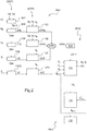
- the figure 2 presents a logic diagram explaining the process implemented by the piloting aid device to determine a collective pitch limit.
- the piloting aid device determines a limiting power margin ⁇ Wlim of the powerplant 6.
- This limiting power margin ⁇ Wlim can be determined by the control and control means 15 of the motor 6, then transmitted to the processing unit 60.
- the processing unit determines a so-called margin "individual margin ⁇ Ng, ⁇ t4, ⁇ Q ⁇ C" respectively for each monitoring parameter Ng, T4, Q, C.
- the processing unit applies a mathematical model 101 of the engine to determine a limit of the speed of rotation of the gas generator Nglim, for example as a function of a P2 gas sampling performed on the engine, a external pressure P0 and an outside temperature T0.
- the processing unit then makes a difference 102 of this limit of the speed of rotation of the gas generator Nglim and the current rotation speed of the gas generator Ng to obtain a first individual margin ⁇ Ng of the rotational speed of the generator gas.
- the mathematical model of the engine may further provide a motor T4lim temperature limit and a Qlim torque limit.
- the processing unit then makes a difference 104 of this temperature limit T4lim and the current temperature T4 to obtain a second individual temperature margin ⁇ t 4.
- the processing unit makes a difference 106 of this torque limit Qlim and the current torque Q of the motor to obtain a third individual margin ⁇ Q of torque.
- the processing unit makes a difference 1060 of the torque limit Clim and the current torque C of the power transmission gearbox to obtain a fourth individual margin ⁇ C of torque.
- the processing unit transforms each individual margin ⁇ Ng, ⁇ t 4 ⁇ Q ⁇ C a respective power headroom of the engine called "individual power margin ⁇ WnG, ⁇ WT4, WQ ⁇ , ⁇ toilet "by applying standard mathematical models.
- the processing unit transforms the first individual margin ⁇ Ng into a first individual power margin ⁇ WNg as a function, in particular, of the external pressure P0 as well as of the outside temperature T0 and the speed of rotation Nr of the main rotor.
- the processing unit can transform the second individual margin ⁇ t 4 into a second individual power margin ⁇ Wt 4 as a function, in particular, of the external pressure P 0 as well as of the external temperature T 0 and the speed of rotation Nr of the main rotor.
- the processing unit can transform the third individual margin ⁇ Q into a third individual power margin ⁇ WQ as a function, in particular, of the rotation speed Nr of the main rotor.
- the processing unit can transform the fourth individual margin ⁇ C into a fourth individual power margin ⁇ WC as a function in particular of the rotation speed Nr of the main rotor.
- the processing unit determines the limiting power margin ⁇ Wlim.
- the limiting power margin ⁇ Wlim is equal to the lowest individual power margin. According to the example of the figure 2 .
- the limiting power margin ⁇ Wlim is equal to the minimum value between the first individual power margin ⁇ WNg, the second individual power margin ⁇ Wt 4 and the third individual power margin ⁇ WQ, or even the fourth individual power margin ⁇ WC .
- the processing unit 60 transforms the limiting power margin ⁇ Wlim into a collective pitch margin ⁇ n representing the margin between a current collective pitch ⁇ n of the main rotor blades and a limit of collective pitch ⁇ limit .
- the processing unit 60 reduces the limiting power margin ⁇ Wlim by a predetermined percentage if the rotation speed Nr of the main rotor 2 decreases at a predetermined speed for a predetermined time.
- the reduction made can be temporary.
- the reduction percentage applied to the limiting power margin ⁇ Wlim decreases from a maximum to a zero value over a predetermined period. For example, this percentage decreases from 25% to zero in two seconds.
- the processing unit determines at each instant of current calculation n a collective pitch margin ⁇ n of the main rotor blades.
- the processing unit applies an algorithm that reduces the collective pitch margin ⁇ n with respect to the real collective pitch margin proportional to the limiting power margin ⁇ lim when the power margin is non-zero in order to anticipate exceeding said power margin. setpoint induced by said regulating means.
- the collective pitch margin ⁇ n is zero when the limiting power margin ⁇ Wlim is zero.
- the processing unit applies for example a recursive algorithm using a main relation providing at each current computation time the margin of collective pitch ⁇ n.
- the main relation expresses the collective pitch margin ⁇ n as a function of the quotient of the limiting power margin ⁇ Wlim and a denominator, this denominator being equal to the product of a first term A1 and a second term A2.
- the first term A1 is also a function of the current collective pitch ⁇ n of the main rotor blades and the collective pitch limit ⁇ limit not - 1 main rotor blades at a previous calculation time n-1 preceding the current computation time n.
- the second term A2 is a function of at least a predetermined coefficient B lowering the power margin of the power plant
- the collective pitch limit ⁇ limit not - 1 is initialized to a predetermined initialization value.
- A1 represents said first term
- " ⁇ limit not - 1 " represents the collective step limit at the previous computation time which precedes the current computation time
- ⁇ n " represents the current collective pitch
- " ⁇ 0 " represents a constant relative to a collective reference step
- "+” represents the sign of the addition
- "-” represents the sign of the subtraction
- "*" represents the sign of the multiplication.
- the coefficient B may be determined by testing by the manufacturer to permanently reduce the calculated collective margin over the actual collective margin.
- the coefficient B may be a variable that varies according to the speed of advance IAS of the aircraft 1.
- the processing unit 60 determines at each computation time the limit of collective pitch ⁇ limit of the blades of the main rotor.
- This limit of collective pitch ⁇ limit is equal to the sum of the collective pitch margin of the main rotor blades and the common collective pitch of the main rotor blades.
- the processing unit requires the display of the current collective pitch and the collective pitch limit ⁇ limit .
- the processing unit comprises a filtering step.
- the value of the collective pitch limit of the main rotor blades at the end of the filtering step is reused during the second step 110 of the second phase PH2 and the first step 111 of the third phase PH3 carried out the next calculation time.
- the filter constant f can be determined for example by tests, and can vary according to the flight phase.
- the processing unit determines the value of the filtering constant as a function of a value of a variable called "variable of a Fpal controller".
- This variable of a control device Fpal is a function of a speed of movement of the control member 9 which controls the pitch of the blades 5 of the auxiliary rotor 4.
- a predetermined relationship or an array of values gives the value of the variable of a control member Fpal as a function of the speed of movement of the control member 9.
- the processing unit 60 determines the value of the filtering constant f as a function of a value of a variable called "Fvit forward variable".
- This variable Fvit advancement is also a function of an IAS forward speed of the aircraft 1. For example, a predetermined relationship or an array of values gives the value of the Fvit forward variable as a function of the speed IAS progress.
- the value of the filtering constant is equal to the product of a predetermined constant and the maximum between the feed variable Fvit and the variable of a control device Fpal.
- the processing unit 60 can freeze the collective pitch limit by keeping it equal to the value of this collective pitch limit at the previous computation step.
- the processing unit can freeze the collective pitch limit during a predetermined aggressive flight phase of the aircraft 1.
- the processing unit may nevertheless inhibit the freezing step if the position of the control member 9 controlling the step of blades 5 of an auxiliary rotor 4 varies at a movement speed greater than a displacement speed threshold.
- the gel step may not be inhibited if the position of the control member 9 controlling the pitch of the blades 5 of an auxiliary rotor 4 varies at a movement speed greater than a displacement threshold and if the collective pitch of the blades 3 of the main rotor 2 varies at a speed greater than a predetermined high speed variation threshold. In this phase of very aggressive flight, the freezing of the limit can not be prohibited.
- the gel step can be performed by keeping the limiting power margin or the collective pitch margin constant, for example.
- the processing unit 60 can assign the filtering constant f a zero value during an aggressive flight phase.
- the value of the filter constant f may then vary during an aggressive flight phase and / or as a function of the value of the variable of a control device Fpal or even of the value of the feed variable Fvit
- the filter constant can be changed.
- this filter constant can be modified to be equal, during a determined transition period, to the filtering constant to be applied in the stabilized flight phase divided by four.
- stabilized flight phase refers to all phases of flight that are not considered aggressive.
- the figure 2 illustrates in particular a logic diagram illustrating the method according to the invention.
- this method can be implemented by applying alternative logigrams.
- an alternative logic diagram could comprise two distinct branches, one branch comprising the steps to be implemented during a stabilized flight phase, and another branch comprising the steps to be implemented during a dynamic flight phase.
Landscapes
- Engineering & Computer Science (AREA)
- Aviation & Aerospace Engineering (AREA)
- Mechanical Engineering (AREA)
- Control Of Turbines (AREA)
- Testing Of Devices, Machine Parts, Or Other Structures Thereof (AREA)
Priority Applications (1)
| Application Number | Priority Date | Filing Date | Title |
|---|---|---|---|
| PL17165759T PL3251955T3 (pl) | 2016-05-30 | 2017-04-10 | Sposób, urządzenie do wspomagania pilotażu statku powietrznego, oraz statek powietrzny |
Applications Claiming Priority (1)
| Application Number | Priority Date | Filing Date | Title |
|---|---|---|---|
| FR1600871A FR3051772B1 (fr) | 2016-05-30 | 2016-05-30 | Procede, dispositif d'aide au pilotage d'un aeronef, et aeronef |
Publications (2)
| Publication Number | Publication Date |
|---|---|
| EP3251955A1 true EP3251955A1 (de) | 2017-12-06 |
| EP3251955B1 EP3251955B1 (de) | 2018-09-26 |
Family
ID=56322010
Family Applications (1)
| Application Number | Title | Priority Date | Filing Date |
|---|---|---|---|
| EP17165759.6A Active EP3251955B1 (de) | 2016-05-30 | 2017-04-10 | Verfahren und hilfsvorrichtung zur steuerung eines luftfahrzeugs, und luftfahrzeug |
Country Status (4)
| Country | Link |
|---|---|
| US (1) | US10252813B2 (de) |
| EP (1) | EP3251955B1 (de) |
| FR (1) | FR3051772B1 (de) |
| PL (1) | PL3251955T3 (de) |
Cited By (1)
| Publication number | Priority date | Publication date | Assignee | Title |
|---|---|---|---|---|
| EP4545406A1 (de) | 2023-10-26 | 2025-04-30 | Airbus Helicopters | Verfahren zur steuerung eines drehflüglers, entsprechendes drehflügelflugzeug und entsprechendes computerprogramm |
Families Citing this family (5)
| Publication number | Priority date | Publication date | Assignee | Title |
|---|---|---|---|---|
| FR3082504B1 (fr) * | 2018-06-14 | 2021-03-05 | Airbus Helicopters | Procede et dispositif de limitation de couple sur un giravion comprenant au moins trois moteurs non equirepartis en puissance |
| US11299286B2 (en) | 2019-05-15 | 2022-04-12 | Pratt & Whitney Canada Corp. | System and method for operating a multi-engine aircraft |
| US11440673B2 (en) * | 2019-11-19 | 2022-09-13 | Ge Aviation Systems Llc | Aircraft propulsion system with voltage regulator |
| US20220169397A1 (en) * | 2020-11-30 | 2022-06-02 | Bell Textron Inc. | Modeling and integrating engine installation deltas |
| FR3134564B1 (fr) | 2022-04-15 | 2024-07-19 | Airbus Helicopters | Procédé et système d'aide au pilotage d'un aéronef, aéronef équipé d’un tel système. |
Citations (6)
| Publication number | Priority date | Publication date | Assignee | Title |
|---|---|---|---|---|
| FR2749545A1 (fr) | 1996-06-07 | 1997-12-12 | Eurocopter France | Indicateur de pilotage pour aeronef |
| FR2756256A1 (fr) | 1996-11-26 | 1998-05-29 | Eurocopter France | Indicateur de marge de puissance pour un aeronef a voilure tournante, notamment un helicoptere |
| FR2802982A1 (fr) | 1999-12-22 | 2001-06-29 | Oreal | Dispositif permettant de recharger en air comprime un recipient |
| FR2809082A1 (fr) * | 2000-05-17 | 2001-11-23 | Eurocopter France | Indicateur de marge de puissance pour un aeronef a voilure tournante, notamment un helicoptere |
| FR2973340A1 (fr) | 2011-03-30 | 2012-10-05 | Eurocopter France | Procede, dispositif d'aide au pilotage d'un aeronef, et aeronef |
| EP2518582A1 (de) | 2011-04-29 | 2012-10-31 | Eurocopter | Übergang von einem Nichtsynchronisierungszustand in einen Synchronisierungszustand zwischen einem Motor und einem Rotor |
Family Cites Families (4)
| Publication number | Priority date | Publication date | Assignee | Title |
|---|---|---|---|---|
| US3744928A (en) * | 1971-10-07 | 1973-07-10 | United Aircraft Corp | Rotor overload protection |
| US6735500B2 (en) * | 2002-06-10 | 2004-05-11 | The Boeing Company | Method, system, and computer program product for tactile cueing flight control |
| US7212942B2 (en) * | 2003-06-10 | 2007-05-01 | Precision Innovations Llc | Power available and limitation indicator for use with an aircraft engine |
| FR2946322B1 (fr) * | 2009-06-04 | 2011-06-17 | Eurocopter France | Dispositif d'aide au pilotage d'un helicoptere hybride, helicoptere hybride muni d'un tel dispositif et procede mis en oeuvre par ledit dispositif |
-
2016
- 2016-05-30 FR FR1600871A patent/FR3051772B1/fr not_active Expired - Fee Related
-
2017
- 2017-04-10 EP EP17165759.6A patent/EP3251955B1/de active Active
- 2017-04-10 PL PL17165759T patent/PL3251955T3/pl unknown
- 2017-05-30 US US15/607,939 patent/US10252813B2/en active Active
Patent Citations (6)
| Publication number | Priority date | Publication date | Assignee | Title |
|---|---|---|---|---|
| FR2749545A1 (fr) | 1996-06-07 | 1997-12-12 | Eurocopter France | Indicateur de pilotage pour aeronef |
| FR2756256A1 (fr) | 1996-11-26 | 1998-05-29 | Eurocopter France | Indicateur de marge de puissance pour un aeronef a voilure tournante, notamment un helicoptere |
| FR2802982A1 (fr) | 1999-12-22 | 2001-06-29 | Oreal | Dispositif permettant de recharger en air comprime un recipient |
| FR2809082A1 (fr) * | 2000-05-17 | 2001-11-23 | Eurocopter France | Indicateur de marge de puissance pour un aeronef a voilure tournante, notamment un helicoptere |
| FR2973340A1 (fr) | 2011-03-30 | 2012-10-05 | Eurocopter France | Procede, dispositif d'aide au pilotage d'un aeronef, et aeronef |
| EP2518582A1 (de) | 2011-04-29 | 2012-10-31 | Eurocopter | Übergang von einem Nichtsynchronisierungszustand in einen Synchronisierungszustand zwischen einem Motor und einem Rotor |
Cited By (3)
| Publication number | Priority date | Publication date | Assignee | Title |
|---|---|---|---|---|
| EP4545406A1 (de) | 2023-10-26 | 2025-04-30 | Airbus Helicopters | Verfahren zur steuerung eines drehflüglers, entsprechendes drehflügelflugzeug und entsprechendes computerprogramm |
| FR3154709A1 (fr) * | 2023-10-26 | 2025-05-02 | Airbus Helicopters | procédé de contrôle d’un giravion, programme d’ordinateur et giravion associés |
| US12595049B2 (en) | 2023-10-26 | 2026-04-07 | Airbus Helicopters | Method for controlling a rotorcraft, associated rotorcraft and computer program |
Also Published As
| Publication number | Publication date |
|---|---|
| US10252813B2 (en) | 2019-04-09 |
| PL3251955T3 (pl) | 2019-02-28 |
| EP3251955B1 (de) | 2018-09-26 |
| FR3051772B1 (fr) | 2019-08-23 |
| US20170341771A1 (en) | 2017-11-30 |
| FR3051772A1 (fr) | 2017-12-01 |
Similar Documents
| Publication | Publication Date | Title |
|---|---|---|
| EP3251955B1 (de) | Verfahren und hilfsvorrichtung zur steuerung eines luftfahrzeugs, und luftfahrzeug | |
| EP2505502B1 (de) | Verfahren, Vorrichtung zur Unterstützung der Steuerung eines Luftfahrzeugs, und Luftfahrzeug | |
| EP3050806B1 (de) | Vorrichtung zur überwachung des leistungsübertragunssystems eines luftfahrzeugs, mit dieser vorrichtung ausgestattetes luftfahrzeug und entsprechendes verfahren | |
| CA2590991C (fr) | Equilibrage en puissance de deux turbomoteurs d'un aeronef | |
| EP3064437B1 (de) | Verfahren und vorrichtung zur bestimmung und optimierung von kennwerten der betriebsfunktion eines drehflügelflugzeugs | |
| CA3050003C (fr) | Procede et dispositif de determination predictive de parametres caracteristiques du fonctionnement d'un aeronef a voilure tournante pour la realisation d'une manoeuvre predeterminee | |
| EP3098579B1 (de) | Verfahren zur schätzung der momentanen masse eines drehflügelfluggerätes | |
| FR3031729A1 (fr) | Commande de puissance pour aeronef a turbopropulseurs | |
| FR2958050A1 (fr) | Procede et systeme de gestion de la variation d'energie d'un aeronef | |
| EP3647192B1 (de) | Pilotenassistenzverfahren und -vorrichtung eines hybrid-drehflügelflugzeugs, das mit einem auftriebsrotor und mindestens einem schuberzeugenden vortriebsrotor ausgestattet ist | |
| FR3097530A1 (fr) | Poignée de pilotage et giravion hybride muni d’un rotor de sustentation et d’au moins un rotor propulsif à hélice générant une poussée | |
| FR2871520A1 (fr) | Indicateur de pilotage permettant de predire l'evolution des parametres de surveillance d'un turbomoteur | |
| FR3097527A1 (fr) | Procédé d’aide au pilotage d’un giravion hybride muni d’un rotor de sustentation et d’au moins un rotor propulsif à hélice générant une poussée | |
| FR2902407A1 (fr) | Procede et dispositif pour determiner le parametre limitant d'un turbomoteur. | |
| EP3882132A1 (de) | Verfahren zum schutz des drehmomentes und/oder schubes von propellern eines hybridhubschraubers und hybridhubschrauber | |
| CA3102691C (fr) | Dispositif de surveillance d'une marge de poussee pour giravion, giravion associe et procede correspondant | |
| EP1904821B1 (de) | Indikator zum lenken eines flugzeuges mit bereitstellung eines leistungsparameters von mindestens einem turbomotor dieses flugzeuges | |
| WO2023099835A1 (fr) | Dispositif d'aide à la régulation des hélices de turbomachines aéronautiques | |
| EP3263462B1 (de) | Anzeigevorrichtung der leistungsbandbreite für ein drehflügelflugzeug, entsprechendes drehflügelflugzeug und entsprechendes verfahren | |
| EP4545406B1 (de) | Verfahren zur steuerung eines drehflüglers, entsprechendes drehflügelflugzeug und entsprechendes computerprogramm | |
| EP4495009B1 (de) | Verfahren zur unterstützung der steuerung eines drehflüglers und drehflügler damit | |
| EP4450399A1 (de) | Verfahren und mehrmotoriges drehflügelflugzeug zur simulation eines motorausfalls |
Legal Events
| Date | Code | Title | Description |
|---|---|---|---|
| PUAI | Public reference made under article 153(3) epc to a published international application that has entered the european phase |
Free format text: ORIGINAL CODE: 0009012 |
|
| STAA | Information on the status of an ep patent application or granted ep patent |
Free format text: STATUS: THE APPLICATION HAS BEEN PUBLISHED |
|
| AK | Designated contracting states |
Kind code of ref document: A1 Designated state(s): AL AT BE BG CH CY CZ DE DK EE ES FI FR GB GR HR HU IE IS IT LI LT LU LV MC MK MT NL NO PL PT RO RS SE SI SK SM TR |
|
| AX | Request for extension of the european patent |
Extension state: BA ME |
|
| STAA | Information on the status of an ep patent application or granted ep patent |
Free format text: STATUS: REQUEST FOR EXAMINATION WAS MADE |
|
| 17P | Request for examination filed |
Effective date: 20171215 |
|
| RBV | Designated contracting states (corrected) |
Designated state(s): AL AT BE BG CH CY CZ DE DK EE ES FI FR GB GR HR HU IE IS IT LI LT LU LV MC MK MT NL NO PL PT RO RS SE SI SK SM TR |
|
| GRAP | Despatch of communication of intention to grant a patent |
Free format text: ORIGINAL CODE: EPIDOSNIGR1 |
|
| RIC1 | Information provided on ipc code assigned before grant |
Ipc: B64D 43/00 20060101AFI20180529BHEP Ipc: B64C 27/04 20060101ALI20180529BHEP |
|
| STAA | Information on the status of an ep patent application or granted ep patent |
Free format text: STATUS: GRANT OF PATENT IS INTENDED |
|
| INTG | Intention to grant announced |
Effective date: 20180705 |
|
| GRAS | Grant fee paid |
Free format text: ORIGINAL CODE: EPIDOSNIGR3 |
|
| GRAA | (expected) grant |
Free format text: ORIGINAL CODE: 0009210 |
|
| STAA | Information on the status of an ep patent application or granted ep patent |
Free format text: STATUS: THE PATENT HAS BEEN GRANTED |
|
| AK | Designated contracting states |
Kind code of ref document: B1 Designated state(s): AL AT BE BG CH CY CZ DE DK EE ES FI FR GB GR HR HU IE IS IT LI LT LU LV MC MK MT NL NO PL PT RO RS SE SI SK SM TR |
|
| REG | Reference to a national code |
Ref country code: GB Ref legal event code: FG4D Free format text: NOT ENGLISH |
|
| REG | Reference to a national code |
Ref country code: CH Ref legal event code: EP |
|
| REG | Reference to a national code |
Ref country code: AT Ref legal event code: REF Ref document number: 1045709 Country of ref document: AT Kind code of ref document: T Effective date: 20181015 |
|
| REG | Reference to a national code |
Ref country code: IE Ref legal event code: FG4D Free format text: LANGUAGE OF EP DOCUMENT: FRENCH |
|
| REG | Reference to a national code |
Ref country code: DE Ref legal event code: R096 Ref document number: 602017000513 Country of ref document: DE |
|
| REG | Reference to a national code |
Ref country code: NL Ref legal event code: MP Effective date: 20180926 |
|
| PG25 | Lapsed in a contracting state [announced via postgrant information from national office to epo] |
Ref country code: BG Free format text: LAPSE BECAUSE OF FAILURE TO SUBMIT A TRANSLATION OF THE DESCRIPTION OR TO PAY THE FEE WITHIN THE PRESCRIBED TIME-LIMIT Effective date: 20181226 Ref country code: NO Free format text: LAPSE BECAUSE OF FAILURE TO SUBMIT A TRANSLATION OF THE DESCRIPTION OR TO PAY THE FEE WITHIN THE PRESCRIBED TIME-LIMIT Effective date: 20181226 Ref country code: GR Free format text: LAPSE BECAUSE OF FAILURE TO SUBMIT A TRANSLATION OF THE DESCRIPTION OR TO PAY THE FEE WITHIN THE PRESCRIBED TIME-LIMIT Effective date: 20181227 Ref country code: LT Free format text: LAPSE BECAUSE OF FAILURE TO SUBMIT A TRANSLATION OF THE DESCRIPTION OR TO PAY THE FEE WITHIN THE PRESCRIBED TIME-LIMIT Effective date: 20180926 Ref country code: RS Free format text: LAPSE BECAUSE OF FAILURE TO SUBMIT A TRANSLATION OF THE DESCRIPTION OR TO PAY THE FEE WITHIN THE PRESCRIBED TIME-LIMIT Effective date: 20180926 Ref country code: FI Free format text: LAPSE BECAUSE OF FAILURE TO SUBMIT A TRANSLATION OF THE DESCRIPTION OR TO PAY THE FEE WITHIN THE PRESCRIBED TIME-LIMIT Effective date: 20180926 |
|
| REG | Reference to a national code |
Ref country code: LT Ref legal event code: MG4D |
|
| PG25 | Lapsed in a contracting state [announced via postgrant information from national office to epo] |
Ref country code: LV Free format text: LAPSE BECAUSE OF FAILURE TO SUBMIT A TRANSLATION OF THE DESCRIPTION OR TO PAY THE FEE WITHIN THE PRESCRIBED TIME-LIMIT Effective date: 20180926 Ref country code: AL Free format text: LAPSE BECAUSE OF FAILURE TO SUBMIT A TRANSLATION OF THE DESCRIPTION OR TO PAY THE FEE WITHIN THE PRESCRIBED TIME-LIMIT Effective date: 20180926 Ref country code: HR Free format text: LAPSE BECAUSE OF FAILURE TO SUBMIT A TRANSLATION OF THE DESCRIPTION OR TO PAY THE FEE WITHIN THE PRESCRIBED TIME-LIMIT Effective date: 20180926 |
|
| REG | Reference to a national code |
Ref country code: AT Ref legal event code: MK05 Ref document number: 1045709 Country of ref document: AT Kind code of ref document: T Effective date: 20180926 |
|
| PG25 | Lapsed in a contracting state [announced via postgrant information from national office to epo] |
Ref country code: ES Free format text: LAPSE BECAUSE OF FAILURE TO SUBMIT A TRANSLATION OF THE DESCRIPTION OR TO PAY THE FEE WITHIN THE PRESCRIBED TIME-LIMIT Effective date: 20180926 Ref country code: IS Free format text: LAPSE BECAUSE OF FAILURE TO SUBMIT A TRANSLATION OF THE DESCRIPTION OR TO PAY THE FEE WITHIN THE PRESCRIBED TIME-LIMIT Effective date: 20190126 Ref country code: AT Free format text: LAPSE BECAUSE OF FAILURE TO SUBMIT A TRANSLATION OF THE DESCRIPTION OR TO PAY THE FEE WITHIN THE PRESCRIBED TIME-LIMIT Effective date: 20180926 Ref country code: CZ Free format text: LAPSE BECAUSE OF FAILURE TO SUBMIT A TRANSLATION OF THE DESCRIPTION OR TO PAY THE FEE WITHIN THE PRESCRIBED TIME-LIMIT Effective date: 20180926 Ref country code: NL Free format text: LAPSE BECAUSE OF FAILURE TO SUBMIT A TRANSLATION OF THE DESCRIPTION OR TO PAY THE FEE WITHIN THE PRESCRIBED TIME-LIMIT Effective date: 20180926 Ref country code: RO Free format text: LAPSE BECAUSE OF FAILURE TO SUBMIT A TRANSLATION OF THE DESCRIPTION OR TO PAY THE FEE WITHIN THE PRESCRIBED TIME-LIMIT Effective date: 20180926 Ref country code: EE Free format text: LAPSE BECAUSE OF FAILURE TO SUBMIT A TRANSLATION OF THE DESCRIPTION OR TO PAY THE FEE WITHIN THE PRESCRIBED TIME-LIMIT Effective date: 20180926 |
|
| PG25 | Lapsed in a contracting state [announced via postgrant information from national office to epo] |
Ref country code: SM Free format text: LAPSE BECAUSE OF FAILURE TO SUBMIT A TRANSLATION OF THE DESCRIPTION OR TO PAY THE FEE WITHIN THE PRESCRIBED TIME-LIMIT Effective date: 20180926 Ref country code: PT Free format text: LAPSE BECAUSE OF FAILURE TO SUBMIT A TRANSLATION OF THE DESCRIPTION OR TO PAY THE FEE WITHIN THE PRESCRIBED TIME-LIMIT Effective date: 20190126 Ref country code: SK Free format text: LAPSE BECAUSE OF FAILURE TO SUBMIT A TRANSLATION OF THE DESCRIPTION OR TO PAY THE FEE WITHIN THE PRESCRIBED TIME-LIMIT Effective date: 20180926 |
|
| REG | Reference to a national code |
Ref country code: DE Ref legal event code: R097 Ref document number: 602017000513 Country of ref document: DE |
|
| PG25 | Lapsed in a contracting state [announced via postgrant information from national office to epo] |
Ref country code: DK Free format text: LAPSE BECAUSE OF FAILURE TO SUBMIT A TRANSLATION OF THE DESCRIPTION OR TO PAY THE FEE WITHIN THE PRESCRIBED TIME-LIMIT Effective date: 20180926 |
|
| PLBE | No opposition filed within time limit |
Free format text: ORIGINAL CODE: 0009261 |
|
| STAA | Information on the status of an ep patent application or granted ep patent |
Free format text: STATUS: NO OPPOSITION FILED WITHIN TIME LIMIT |
|
| 26N | No opposition filed |
Effective date: 20190627 |
|
| PG25 | Lapsed in a contracting state [announced via postgrant information from national office to epo] |
Ref country code: SI Free format text: LAPSE BECAUSE OF FAILURE TO SUBMIT A TRANSLATION OF THE DESCRIPTION OR TO PAY THE FEE WITHIN THE PRESCRIBED TIME-LIMIT Effective date: 20180926 |
|
| REG | Reference to a national code |
Ref country code: DE Ref legal event code: R119 Ref document number: 602017000513 Country of ref document: DE |
|
| REG | Reference to a national code |
Ref country code: BE Ref legal event code: MM Effective date: 20190430 |
|
| PG25 | Lapsed in a contracting state [announced via postgrant information from national office to epo] |
Ref country code: LU Free format text: LAPSE BECAUSE OF NON-PAYMENT OF DUE FEES Effective date: 20190410 Ref country code: MC Free format text: LAPSE BECAUSE OF FAILURE TO SUBMIT A TRANSLATION OF THE DESCRIPTION OR TO PAY THE FEE WITHIN THE PRESCRIBED TIME-LIMIT Effective date: 20180926 |
|
| PG25 | Lapsed in a contracting state [announced via postgrant information from national office to epo] |
Ref country code: DE Free format text: LAPSE BECAUSE OF NON-PAYMENT OF DUE FEES Effective date: 20191101 |
|
| PG25 | Lapsed in a contracting state [announced via postgrant information from national office to epo] |
Ref country code: BE Free format text: LAPSE BECAUSE OF NON-PAYMENT OF DUE FEES Effective date: 20190430 |
|
| PG25 | Lapsed in a contracting state [announced via postgrant information from national office to epo] |
Ref country code: TR Free format text: LAPSE BECAUSE OF FAILURE TO SUBMIT A TRANSLATION OF THE DESCRIPTION OR TO PAY THE FEE WITHIN THE PRESCRIBED TIME-LIMIT Effective date: 20180926 |
|
| PG25 | Lapsed in a contracting state [announced via postgrant information from national office to epo] |
Ref country code: IE Free format text: LAPSE BECAUSE OF NON-PAYMENT OF DUE FEES Effective date: 20190410 |
|
| REG | Reference to a national code |
Ref country code: CH Ref legal event code: PL |
|
| PG25 | Lapsed in a contracting state [announced via postgrant information from national office to epo] |
Ref country code: CH Free format text: LAPSE BECAUSE OF NON-PAYMENT OF DUE FEES Effective date: 20200430 Ref country code: LI Free format text: LAPSE BECAUSE OF NON-PAYMENT OF DUE FEES Effective date: 20200430 |
|
| PG25 | Lapsed in a contracting state [announced via postgrant information from national office to epo] |
Ref country code: CY Free format text: LAPSE BECAUSE OF FAILURE TO SUBMIT A TRANSLATION OF THE DESCRIPTION OR TO PAY THE FEE WITHIN THE PRESCRIBED TIME-LIMIT Effective date: 20180926 |
|
| PG25 | Lapsed in a contracting state [announced via postgrant information from national office to epo] |
Ref country code: SE Free format text: LAPSE BECAUSE OF NON-PAYMENT OF DUE FEES Effective date: 20180926 |
|
| PG25 | Lapsed in a contracting state [announced via postgrant information from national office to epo] |
Ref country code: MT Free format text: LAPSE BECAUSE OF FAILURE TO SUBMIT A TRANSLATION OF THE DESCRIPTION OR TO PAY THE FEE WITHIN THE PRESCRIBED TIME-LIMIT Effective date: 20180926 Ref country code: HU Free format text: LAPSE BECAUSE OF FAILURE TO SUBMIT A TRANSLATION OF THE DESCRIPTION OR TO PAY THE FEE WITHIN THE PRESCRIBED TIME-LIMIT; INVALID AB INITIO Effective date: 20170410 |
|
| GBPC | Gb: european patent ceased through non-payment of renewal fee |
Effective date: 20210410 |
|
| PG25 | Lapsed in a contracting state [announced via postgrant information from national office to epo] |
Ref country code: GB Free format text: LAPSE BECAUSE OF NON-PAYMENT OF DUE FEES Effective date: 20210410 |
|
| PG25 | Lapsed in a contracting state [announced via postgrant information from national office to epo] |
Ref country code: MK Free format text: LAPSE BECAUSE OF FAILURE TO SUBMIT A TRANSLATION OF THE DESCRIPTION OR TO PAY THE FEE WITHIN THE PRESCRIBED TIME-LIMIT Effective date: 20180926 |
|
| P01 | Opt-out of the competence of the unified patent court (upc) registered |
Effective date: 20230530 |
|
| PGFP | Annual fee paid to national office [announced via postgrant information from national office to epo] |
Ref country code: PL Payment date: 20250328 Year of fee payment: 9 |
|
| PGFP | Annual fee paid to national office [announced via postgrant information from national office to epo] |
Ref country code: IT Payment date: 20250424 Year of fee payment: 9 |
|
| PGFP | Annual fee paid to national office [announced via postgrant information from national office to epo] |
Ref country code: FR Payment date: 20250425 Year of fee payment: 9 |