EP3251981A1 - Chariot pour un système de transport sur rails et système de transport comprenant un tel chariot - Google Patents
Chariot pour un système de transport sur rails et système de transport comprenant un tel chariot Download PDFInfo
- Publication number
- EP3251981A1 EP3251981A1 EP17171864.6A EP17171864A EP3251981A1 EP 3251981 A1 EP3251981 A1 EP 3251981A1 EP 17171864 A EP17171864 A EP 17171864A EP 3251981 A1 EP3251981 A1 EP 3251981A1
- Authority
- EP
- European Patent Office
- Prior art keywords
- carriage
- rollers
- roller
- roller set
- rail
- Prior art date
- Legal status (The legal status is an assumption and is not a legal conclusion. Google has not performed a legal analysis and makes no representation as to the accuracy of the status listed.)
- Granted
Links
Images




Classifications
-
- B—PERFORMING OPERATIONS; TRANSPORTING
- B65—CONVEYING; PACKING; STORING; HANDLING THIN OR FILAMENTARY MATERIAL
- B65G—TRANSPORT OR STORAGE DEVICES, e.g. CONVEYORS FOR LOADING OR TIPPING, SHOP CONVEYOR SYSTEMS OR PNEUMATIC TUBE CONVEYORS
- B65G9/00—Apparatus for assisting manual handling having suspended load-carriers movable by hand or gravity
- B65G9/008—Rails or switches
-
- B—PERFORMING OPERATIONS; TRANSPORTING
- B61—RAILWAYS
- B61B—RAILWAY SYSTEMS; EQUIPMENT THEREFOR NOT OTHERWISE PROVIDED FOR
- B61B3/00—Elevated railway systems with suspended vehicles
-
- B—PERFORMING OPERATIONS; TRANSPORTING
- B65—CONVEYING; PACKING; STORING; HANDLING THIN OR FILAMENTARY MATERIAL
- B65G—TRANSPORT OR STORAGE DEVICES, e.g. CONVEYORS FOR LOADING OR TIPPING, SHOP CONVEYOR SYSTEMS OR PNEUMATIC TUBE CONVEYORS
- B65G35/00—Mechanical conveyors not otherwise provided for
-
- B—PERFORMING OPERATIONS; TRANSPORTING
- B65—CONVEYING; PACKING; STORING; HANDLING THIN OR FILAMENTARY MATERIAL
- B65G—TRANSPORT OR STORAGE DEVICES, e.g. CONVEYORS FOR LOADING OR TIPPING, SHOP CONVEYOR SYSTEMS OR PNEUMATIC TUBE CONVEYORS
- B65G9/00—Apparatus for assisting manual handling having suspended load-carriers movable by hand or gravity
- B65G9/002—Load-carriers, rollers therefor
-
- B—PERFORMING OPERATIONS; TRANSPORTING
- B65—CONVEYING; PACKING; STORING; HANDLING THIN OR FILAMENTARY MATERIAL
- B65H—HANDLING THIN OR FILAMENTARY MATERIAL, e.g. SHEETS, WEBS, CABLES
- B65H29/00—Delivering or advancing articles from machines; Advancing articles to or into piles
- B65H29/003—Delivering or advancing articles from machines; Advancing articles to or into piles by grippers
Definitions
- the present invention relates to the field of conveyor technology. It relates to a carriage for a rail-guided conveyor system according to the preamble of claim 1.
- Gravity conveyors in particular gravity-conveying systems, are characterized, inter alia, by the fact that they enable a shift in the conveyance of goods from the ground into otherwise unused spatial areas inside or outside of buildings. Often, overhead conveyors are therefore attached overhead to girders attached to the ceiling, walls, or individual pillars attached to the floor.
- Overhead conveyor systems also find use as buffers between two or more work processes at different speeds.
- networked processes can be decoupled temporally and / or spatially, with which, for example, faults in processes can be remedied without stopping the remaining parts of a process chain to have to.
- clock differences in the processing can be cushioned.
- Gravity-conveying conveyors are particularly suitable for the construction of buffers in many areas. This on the one hand due to the already mentioned better space utilization. On the other hand, they are relatively energy-saving, since unlike forced-conveyed overhead conveyor systems, they do not provide drive means along the rails, e.g. Need drive chains and usually have only a few short positively conveyed track parts. As a result, gravity conveyor can also be relatively easily and inexpensively reduced or increased targeted to changing production requirements.
- transport bodies used also called shuttles
- transport bodies have consistently good running properties.
- transport bodies do not unintentionally decelerate or even come to a halt on gravitationally conveyed railway parts, since this would lead to delays or interruptions in the conveyance.
- a transport body for gravity conveyor therefore mostly carriages are used with wheels or rollers, since these generally have a lower resistance to movement than those with so-called gliders, which in turn have a speed-dependent resistance to movement.
- a conveyor for a conveyor having a trained to encompass a running rail carriage body comprising a first and a second leg, which are connected by a connecting portion, wherein the first leg on its inside having attached first rollers and the second leg has mounted on its inside second rollers and the connecting portion has mounted on its inside third rollers.
- the first and second rollers are standing and the third rollers are arranged horizontally.
- a run-safe carriage especially for a gravity conveyor, provided.
- Such a carriage is suitable for goods of different dimensions and / or masses and for conveyor lines with almost any trajectory.
- such a carriage can be manufactured at a relatively low unit price.
- WO 2016/030275 A1 a functionally reliable and simple conveyor system, in particular gravity conveyor, realize.
- a rail-guided means of transport in particular for conveying printed products, proposed, which comprises a transport body with two legs, which have two crosswise offset staggered sliding or rolling means on the mutually associated sides, wherein the sliding or rolling means in the direction of the legs so arranged mutually spaced, that a guide rail between the sliding or rolling means place.
- the denser packing of the transport is mainly achieved by drastically reducing the extent of the transport in the transport direction and moves in the direction of successively arranged rollers as close to each other as possible.
- Fig. 6 of the EP 0 856 480 A1 achieved a slight nesting of the means of transport.
- the carriage according to the invention is provided for a rail-guided conveyor system, in particular a gravity conveyor, in which conveyor system a plurality of identical carriages are mounted on a rail extending in a rail longitudinal direction in the rail longitudinal direction one behind the other and in the rail longitudinal direction, wherein the carriage for guiding in the running rail in Rail longitudinal direction arranged one behind the other has a first and a second set of stationary rollers, which are rotatably mounted on a carriage body each transverse to the rail longitudinal direction about an associated axis and spaced along the associated axis.
- the inner distance of the rollers in the first roller set by a predetermined amount is greater than the outer distance of the rollers in the second roller set, and that the storage of the first and second pairs of rollers on the carriage body is designed such that two successive carriages save space can be pushed into each other. This is where the second roller set of a carriage between the roll of the first roller set of the other carriage to lie.
- roller sets each form a pair of rollers.
- roller sets with more than two rollers per set, in particular with several pairs of rollers.
- An embodiment of the carriage according to the invention is characterized in that the carriage body is formed for engaging around the running rail and comprises a first and second leg, which are spaced apart from each other transversely to the rail longitudinal direction and interconnected by a connecting portion, and that the rollers of the first roller set respectively are rotatably arranged on the inside of the legs.
- first support bracket is formed, in particular integrally formed, at the free ends of the rollers of the second roller set are rotatably arranged.
- the rollers of the first and second roller set may be arranged mirror-symmetrically to a vertical plane of symmetry of the carriage.
- the carriage may have a third roller set with a first and second horizontal roller, wherein the horizontal rollers of the third roller set are arranged on the inside of the connecting portion in the rail longitudinal direction one behind the other, the axes of the rollers of the third roller set are in the vertical plane of symmetry of the carriage and the first idler pulley is disposed higher than the second idler pulley by a predetermined amount, such that when two consecutive carriages are pushed together to save space, the first lying roller of a carriage over the second horizontal roller of the other carriage comes to rest.
- the second lying roller can be arranged rotatably directly on the top of the connecting portion, wherein the first roller lying rotatably disposed at the free end of a second support bracket, the outgoing on the second roller lying inwardly outgoing and buckling in the rail longitudinal direction on the inside of the connecting portion formed, in particular molded, is.
- a material to be conveyed can be releasably secured.
- a further embodiment of the carriage according to the invention is characterized in that the rollers of the first roller set are designed as ball bearings overmolded with a roller body.
- the rollers of the first roller set may be wider than the rollers of the second roller set.
- a, in particular pin-shaped, coupling element may be arranged, via which an engagement on the carriage with an external element can be realized.
- the carriage body is integrally formed.
- the conveyor system according to the invention comprises at least one carriage according to the invention and at least one running rail tuned to the carriage.
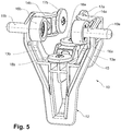
- Fig. 1 and Fig. 2 is a section of a conveyor system or conveyor 100 according to an embodiment of the invention in a side view ( Fig. 1 ) and a perspective view obliquely from above ( Fig. 2 ).
- the figures show a portion of a running rail 20 that extends straight in a rail longitudinal direction, comprising two opposing, side, outwardly open, U-shaped guide channels 20a and 20b and a central, downwardly open, U-shaped guide channel 20c.
- the guide channels 20a, 20b and 20c extend parallel in the rail longitudinal direction (further details of the running rail can the WO 2016/030274 A1 be removed).
- a first and a second set of stationary rollers 16a, 16b and 1 7a, 1 7b are formed as pairs in the example.
- the first roller set 16a, 16b is in a first vertical and perpendicular to the direction oriented plane E2 (FIG. Fig. 7 ) arranged.
- the second roller set 17a, 17b is in a second vertical and perpendicular to the direction oriented plane E3 (FIG. Fig. 7 ) arranged.
- the rollers 16a, b and 1 7a, b are rotatably mounted on a carriage body 11 comprising the running rail 20 from below in each case transverse to the rail longitudinal direction in the planes E2 and E3 about an associated axis (A1 or A2) and along the associated axis (A1 or A2) spaced from each other.
- the inner distance (D1 in Fig. 6 ) of the rollers 16a, b in the first roller set is greater by a predetermined amount than the outer distance (D2 in Fig. 4 ) of the rollers 1 7a, b in the second roller set. This measure is chosen so that the second roller set 1 7a, b of an adjacent carriage between the rollers 16a, b of the first roller set can be added.
- the mounting of the first and second roller sets 16a, b or 17a, b on the carriage body 11 is designed such that two successive carriages (eg the carriages 10a and 10b in FIG Fig. 1 ) are pushed together to save space can, by the second roller set 1 7a, b of a carriage 10a between the first roller set 16a, b of the other carriage 10b comes to rest.
- the carriage body 11, which - as already mentioned - is designed to engage around the running rail 20, has a first and second legs 13a and 13b.
- the two legs are spaced apart transversely to the rail longitudinal axis or rail longitudinal direction and connected to one another by a connecting portion 11a.
- the rollers 1 6a, b of the first roller set are in each case rotatably arranged on the inside of the legs 13a, b.
- the rollers 16a, b of the first roller set which receive the largest part of the load due to the geometry of the carriage body 11, are several times wider than the rollers 17a, b of the second roller set.
- the rollers 16a, b of the first roller set are ball-mounted, preferably designed as a roller body with overmolded ball bearings.
- the rollers 17a, b of the second roller set are designed rather as narrow wheels, which are rotatably mounted on a shaft without special storage means.
- rollers 17a, b of the second roller set relative to the rollers 16a, b of the first roller set can be arranged offset inwards, are on the inner sides of the legs 13a, b next to the rollers 16a, b of the first roller set and the rollers 16a, B of the first roller set out inwardly outgoing and bent in the rail longitudinal direction SLR first support bracket 14a, b formed, in particular integrally formed, at the free ends on the inside of the rollers 17a, b of the second roller set are rotatably arranged.
- a third roller set with a first and second horizontal rollers 18a and 18b, which is received by the lower guide channel 20c of the track rail 20.
- the horizontal rollers 18a, b of the third roller set which are also designed as narrow wheels, are arranged on the inside of the connecting portion 11a in the rail longitudinal direction SLR one behind the other.
- the axes A3 and A4 of the rollers 18a, b of the third roller set are preferably in the vertical plane of symmetry E1, to which the rollers 16a, b and 17a, b of the first and second roller set are arranged mirror-symmetrically.
- the axes A3 and A4 of the rollers 18a, b of the third roller set can also be to influence the running behavior, in particular for the purpose of self-centering, obliquely to the plane of symmetry E1.
- the first idler pulley 18a is positioned higher than the second idler pulley 18b by a predetermined amount so that when two consecutive pulleys 18a, e.g. the carriages 10a and 10b are pushed into one another to save space, the first lying roller 18a of the one carriage 10a comes to lie over the second horizontal roller 18b of the other carriage 10b.
- the second horizontal roller 18b is rotatably mounted directly on the top of the connecting portion 11a, while the first horizontal roller 18a is rotatably disposed at the free end of a second support bracket 15 which is disposed over the second horizontal roller 18b outgoing inwardly and in the rail longitudinal direction SLR bent on the inside of the connecting portion 11a formed, in particular integrally formed, is.
- a fastening section 12 in the form of an eyelet or an eye 21 is provided on the carriage body 11 downwards from the connecting section 11a, to which a product to be conveyed is detachably fastened, e.g. can be hooked. If something is hooked into the eyelet, due to the shape of the eyelet 21 it slips by itself into the lowest position, which is below the rollers 1 6a, b of the first roller set, so that a direct load introduction is ensured in these roles.
- one of the first and second legs 13a and 13b projects transversely to the rail longitudinal direction SLR outwardly, in particular a pin-shaped, coupling element 19a or 19b arranged, via which an engagement on the carriage 10 with an external element can be realized.
- Other types of coupling elements are also conceivable.
- the carriage body 11 is preferably formed as a one-piece casting and may consist of a suitable plastic but also of metal.
- the conveyor system constructed with the carriage according to the invention is characterized not only by a functionally reliable, low-wear operation, in particular by means of gravity, but also enables higher conveying capacities and a significantly increased bearing density, above all because of the nesting function of the carriages.
Landscapes
- Engineering & Computer Science (AREA)
- Mechanical Engineering (AREA)
- Transportation (AREA)
- Rollers For Roller Conveyors For Transfer (AREA)
- Intermediate Stations On Conveyors (AREA)
- Chain Conveyers (AREA)
- Printing Methods (AREA)
Priority Applications (1)
| Application Number | Priority Date | Filing Date | Title |
|---|---|---|---|
| PL17171864T PL3251981T3 (pl) | 2016-05-31 | 2017-05-19 | Wózek do systemu przenośnikowego z prowadzeniem szynowym i system przenośnikowy zawierający taki wózek |
Applications Claiming Priority (1)
| Application Number | Priority Date | Filing Date | Title |
|---|---|---|---|
| CH00694/16A CH712560A1 (de) | 2016-05-31 | 2016-05-31 | Laufwagen für ein schienengeführtes Fördersystem sowie Fördersystem mit einem solchen Laufwagen. |
Publications (2)
| Publication Number | Publication Date |
|---|---|
| EP3251981A1 true EP3251981A1 (fr) | 2017-12-06 |
| EP3251981B1 EP3251981B1 (fr) | 2018-12-26 |
Family
ID=58745097
Family Applications (1)
| Application Number | Title | Priority Date | Filing Date |
|---|---|---|---|
| EP17171864.6A Active EP3251981B1 (fr) | 2016-05-31 | 2017-05-19 | Chariot pour un système de transport sur rails et système de transport comprenant un tel chariot |
Country Status (7)
| Country | Link |
|---|---|
| US (1) | US10703568B2 (fr) |
| EP (1) | EP3251981B1 (fr) |
| CN (1) | CN107444829B (fr) |
| AU (1) | AU2017203325B2 (fr) |
| CH (1) | CH712560A1 (fr) |
| ES (1) | ES2716957T3 (fr) |
| PL (1) | PL3251981T3 (fr) |
Families Citing this family (7)
| Publication number | Priority date | Publication date | Assignee | Title |
|---|---|---|---|---|
| CH713398A1 (de) | 2017-01-31 | 2018-07-31 | Ferag Ag | Vorrichtung zum Entleeren hängend geförderter Transporttaschen. |
| CH713399A1 (de) | 2017-01-31 | 2018-07-31 | Ferag Ag | Fördereinheit zum hängenden Transport von Transportelementen in zwei Positionen. |
| EP3315433B1 (fr) | 2016-11-01 | 2020-07-15 | Ferag AG | Dispositif de transmission pour support de produits doté des moyens de retenue |
| US11878876B2 (en) | 2017-01-31 | 2024-01-23 | Ferag Ag | Device for emptying transport bags conveyed in a suspended manner |
| US11059498B2 (en) * | 2018-06-08 | 2021-07-13 | Castree Projects Limited | Trolley |
| EP3983321B1 (fr) * | 2019-06-14 | 2024-09-18 | Kannegiesser Etech | Appareil pour déplacer des articles le long d'un rail |
| CN117719826A (zh) * | 2023-12-26 | 2024-03-19 | 上汽通用五菱汽车股份有限公司 | 一种无人投送料架 |
Citations (3)
| Publication number | Priority date | Publication date | Assignee | Title |
|---|---|---|---|---|
| EP0856480A1 (fr) | 1997-01-31 | 1998-08-05 | IPT Weinfelden AG | Moyen de transport guidé sur rails et système de transport avec un tel moyen de transport |
| WO2016030274A1 (fr) | 2014-08-27 | 2016-03-03 | Ferag Ag | Rail de roulement et son procédé de fabrication |
| WO2016030275A1 (fr) | 2014-08-27 | 2016-03-03 | Ferag Ag | Chariot pour un convoyeur, notamment pour un convoyeur par gravité, système convoyeur et procédé de fonctionnement de ce dernier |
Family Cites Families (40)
| Publication number | Priority date | Publication date | Assignee | Title |
|---|---|---|---|---|
| US474973A (en) | 1892-05-17 | Cash-carrier | ||
| DE247498C (fr) * | 1911-01-05 | 1912-05-31 | ||
| GB788799A (en) | 1955-02-22 | 1958-01-08 | Track Installations Ltd | Improvements in or relating to segregator conveyors |
| FR1320848A (fr) * | 1962-01-31 | 1963-03-15 | Reunis Pour La Fabrication D A | Chariot pour le transport d'objets divers |
| US3694018A (en) | 1970-07-22 | 1972-09-26 | Gen Motors Corp | Elastomeric impact energy dissipator |
| US3982623A (en) | 1975-12-11 | 1976-09-28 | W. M. Cissell Manufacturing Company | Pick off device |
| DE7715547U1 (de) | 1977-05-16 | 1978-08-10 | Herbert Kannegiesser Kg, 4973 Vlotho | Vorrichtung zum zufuehren von kleiderbuegeln zu einer behandlungsstation zur behandlung von bekleidung und zum nachfolgenden abfoerdern derselben |
| DE2902724A1 (de) | 1979-01-25 | 1980-08-07 | Sandt Ag J | Foerdereinrichtung fuer mit einem aufhaengeglied versehene foerderguttraeger |
| DE8604435U1 (de) | 1986-02-19 | 1986-04-30 | Wilfried Pavel Maschinenbau, 33790 Halle | Übergabevorrichtung für Bekleidungsstücke |
| DE3819102C1 (fr) | 1988-06-04 | 1989-10-12 | Jennewein, Manfred A., 6082 Moerfelden-Walldorf, De | |
| US5269402A (en) | 1991-01-22 | 1993-12-14 | White Conveyors, Inc. | Apparatus for conveying |
| EP0511159B1 (fr) | 1991-04-24 | 1996-07-03 | Ferag AG | Procédé et dispositif pour réaliser des liasses de produits imprimés variés |
| DE4117991A1 (de) | 1991-06-03 | 1992-12-10 | Sussman Jennewein Bekleidungst | Vorrichtung zum beladen eines foerderers mit auf kleiderbuegeln haengenden kleidungsstuecken |
| DE4326095C1 (de) | 1993-08-04 | 1995-01-26 | Psb Foerderanlagen | Aufgabevorrichtung an einem Hängeförderer |
| DE4427027C2 (de) | 1994-07-29 | 1997-02-06 | Franz Gaertner | Übernahmevorrichtung |
| DE19514604C2 (de) | 1995-04-20 | 1997-09-04 | Duerkopp Adler Ag | Vorrichtung zum Vereinzeln von übereinander verkreuzten Bügelhaken |
| US6199682B1 (en) | 1995-11-15 | 2001-03-13 | Rosebay Terrace Pty Ltd. | Conveyor loading apparatus |
| DE19615773C2 (de) | 1996-04-20 | 1998-06-04 | Duerkopp Adler Ag | Verfahren zum Vereinzeln von Förderträgern |
| CA2259405A1 (fr) | 1996-07-19 | 1998-01-29 | Walter Reist | Dispositif pour acheminer des produits d'imprimerie vers des postes de traitement |
| US5975280A (en) | 1996-09-09 | 1999-11-02 | Heidelberger Druckmaschinen | Device for transporting flat products to further processing units or delivery stations |
| EP0854105B1 (fr) | 1997-01-16 | 2001-08-08 | Ferag AG | Méthode et dispositif pour traiter des produits imprimes plats, comme des journaux, des magazines, et des parties de cela |
| AUPO871697A0 (en) | 1997-08-22 | 1997-09-18 | Rosebay Terrace Pty Ltd | Article transfer apparatus |
| DE19829484C1 (de) | 1998-07-01 | 1999-11-11 | Siemens Ag | Vorrichtung und Verfahren zum Erzeugen eines Gesamtstapels |
| ATE264257T1 (de) | 2000-07-07 | 2004-04-15 | Ferag Ag | Verfahren und vorrichtung zur gehaltenen förderung von gegenständen auf einer förderstrecke mit pufferspeicher |
| DK1330406T3 (da) | 2000-11-02 | 2007-01-08 | Ferag Ag | Anordning til forarbejdning af trykkeriprodukter |
| DE10152926A1 (de) | 2001-10-26 | 2003-05-08 | Wf Logistik Gmbh | Schneckenförderer zum Transport von an Hängeträgern hängendem Fördergut |
| DE202006001607U1 (de) * | 2006-02-02 | 2007-06-14 | Wampfler Aktiengesellschaft | Fahrwerk für einen Leitungswagen |
| DE102006049754B3 (de) | 2006-10-21 | 2007-12-20 | Dürkopp Adler AG | Zuführ-Transport-System für Bügel mit darauf hängenden Gegenständen |
| DE102006056943A1 (de) | 2006-11-30 | 2008-06-12 | A20 Ag | Verfahren zum Transport von Gegenständen |
| CA2661063C (fr) | 2008-04-03 | 2016-06-21 | Ferag Ag | Methode et dispositif de creation de circulation de produits plats selon une sequence predeterminee |
| US8388299B2 (en) | 2008-04-18 | 2013-03-05 | R. R. Donnelley & Sons Company | Systems and methods to produce and sequence a plurality of different books |
| DE102008057630A1 (de) | 2008-11-10 | 2010-05-27 | Langen, Manfred | Kommissionieranlage und Verfahren zum Betreiben derselben mit einem Kommissionierwagen |
| DE102009021382B4 (de) | 2009-05-14 | 2013-07-25 | Kugler-Womako Gmbh | Herstellung von gebundenen Papierprodukten |
| KR101397781B1 (ko) * | 2009-06-02 | 2014-05-20 | 빔웨이즈 에이비 | 매달리는 차량용 트랙 및 보우기 |
| CN202006989U (zh) * | 2011-03-02 | 2011-10-12 | 厦门美厦工艺品有限公司 | 货物传输轨道车 |
| CH706437A1 (de) | 2012-04-25 | 2013-10-31 | Ferag Ag | Verfahren und Vorrichtung zum Erstellen eines Produktstroms von Produkteinheiten in einer vorgegebenen Sequenz. |
| CN103538608B (zh) | 2012-07-17 | 2016-06-29 | 美固龙金属制品(中国)有限公司 | 平板推车 |
| DE102012015040A1 (de) | 2012-07-28 | 2014-05-15 | Volkswagen Aktiengesellschaft | Schwerkraftförderanlage |
| EP2692667A1 (fr) | 2012-08-01 | 2014-02-05 | Dürkopp Fördertechnik GmbH | Transstockeur pour entrepôt, entrepôt doté d'un tel transstockeur et procédé pour la saisie individuelle d'une marchandise dans un tel entrepôt |
| CH707799A1 (de) | 2013-03-28 | 2014-09-30 | Ferag Ag | Verfahren und Einrichtung zum Übergeben von Stückgütern an eine Förderanlage. |
-
2016
- 2016-05-31 CH CH00694/16A patent/CH712560A1/de not_active Application Discontinuation
-
2017
- 2017-05-18 AU AU2017203325A patent/AU2017203325B2/en active Active
- 2017-05-19 PL PL17171864T patent/PL3251981T3/pl unknown
- 2017-05-19 ES ES17171864T patent/ES2716957T3/es active Active
- 2017-05-19 EP EP17171864.6A patent/EP3251981B1/fr active Active
- 2017-05-25 US US15/605,544 patent/US10703568B2/en active Active
- 2017-05-26 CN CN201710385863.9A patent/CN107444829B/zh active Active
Patent Citations (3)
| Publication number | Priority date | Publication date | Assignee | Title |
|---|---|---|---|---|
| EP0856480A1 (fr) | 1997-01-31 | 1998-08-05 | IPT Weinfelden AG | Moyen de transport guidé sur rails et système de transport avec un tel moyen de transport |
| WO2016030274A1 (fr) | 2014-08-27 | 2016-03-03 | Ferag Ag | Rail de roulement et son procédé de fabrication |
| WO2016030275A1 (fr) | 2014-08-27 | 2016-03-03 | Ferag Ag | Chariot pour un convoyeur, notamment pour un convoyeur par gravité, système convoyeur et procédé de fonctionnement de ce dernier |
Also Published As
| Publication number | Publication date |
|---|---|
| CN107444829A (zh) | 2017-12-08 |
| CH712560A1 (de) | 2017-12-15 |
| PL3251981T3 (pl) | 2019-06-28 |
| AU2017203325B2 (en) | 2023-01-12 |
| US10703568B2 (en) | 2020-07-07 |
| US20170341864A1 (en) | 2017-11-30 |
| CN107444829B (zh) | 2020-12-18 |
| AU2017203325A1 (en) | 2017-12-14 |
| ES2716957T3 (es) | 2019-06-18 |
| EP3251981B1 (fr) | 2018-12-26 |
Similar Documents
| Publication | Publication Date | Title |
|---|---|---|
| EP3251981B1 (fr) | Chariot pour un système de transport sur rails et système de transport comprenant un tel chariot | |
| EP2784009B1 (fr) | Procédé et dispositif de transfert de marchandises au détail au niveau d'une installation de transport | |
| DE69500173T2 (de) | Vorrichtung zum ausrichten und gruppieren von gegenständen, wie dosen, flaschen u. dgl. | |
| EP3181493B1 (fr) | Organe de transport guidé par galet et installation de transport comprenant de tels organes de transport | |
| AT500109B1 (de) | Übergabevorrichtung zum seitlichen ausschleusen von fördergut sowie eine fördereinrichtung | |
| CH707798A1 (de) | Schienengeführtes Fördermittel und Förderanlage mit derartigen Fördermitteln. | |
| WO1988007968A1 (fr) | Dispositif de commande du trajet de deplacement d'objets | |
| DE102008008009A1 (de) | Fördereinrichtung zum vertikalen Transport von Stückgut | |
| DE102013107582A1 (de) | Speicherabschnitt einer Fördereinrichtung und Verfahren zum Zwischenspeichern von Artikeln | |
| DE202012013047U1 (de) | Vorrichtung zum Sammeln von Produkten sowie Anlage mit einer solchen Vorrichtung | |
| EP2767492B1 (fr) | Dispositif de convoyage doté d'un organe de transport à extension plane et un cadre modulaire | |
| EP2314529B1 (fr) | Unité de transport dotée de chaînes à petits rouleaux de retenue | |
| DE2537943A1 (de) | Endloser kettenfoerderer, insbesondere fuer kraftfahrzeuge | |
| WO2003020617A1 (fr) | Element de courbe capable de retenir des articles, pour un systeme de transfert | |
| DE102011118303A1 (de) | Förderanlage mit einer Förderkette und Tragsegment für einen Förderträger einer Förderkette | |
| DE4319164A1 (de) | Förderer, insbesondere Stetigförderer für Einzelbügel | |
| WO2002081342A1 (fr) | Elevateur se presentant sous la forme d'un elevateur a circulation en « c » conçu pour le transport vertical de produits de detail | |
| EP3044132B1 (fr) | Système de transport | |
| EP2330059A1 (fr) | Transporteur vertical | |
| EP3056455A1 (fr) | Unite de chaines d'amenee | |
| EP2984009B1 (fr) | Dispositif de conservation limitée dans le temps d'objets | |
| DE2352424A1 (de) | Foerderer zum transport von zeitungsstoessen bzw. -paketen | |
| EP3064454B1 (fr) | Chaine de transport d'articles et systeme de transport dote de ladite chaine de transport | |
| EP2921429B1 (fr) | Dispositif et procédé de freinage de chariot roulant d'un dispositif de transport | |
| DE19816960A1 (de) | Fördergut-Bremseinrichtung |
Legal Events
| Date | Code | Title | Description |
|---|---|---|---|
| PUAI | Public reference made under article 153(3) epc to a published international application that has entered the european phase |
Free format text: ORIGINAL CODE: 0009012 |
|
| STAA | Information on the status of an ep patent application or granted ep patent |
Free format text: STATUS: THE APPLICATION HAS BEEN PUBLISHED |
|
| AK | Designated contracting states |
Kind code of ref document: A1 Designated state(s): AL AT BE BG CH CY CZ DE DK EE ES FI FR GB GR HR HU IE IS IT LI LT LU LV MC MK MT NL NO PL PT RO RS SE SI SK SM TR |
|
| AX | Request for extension of the european patent |
Extension state: BA ME |
|
| STAA | Information on the status of an ep patent application or granted ep patent |
Free format text: STATUS: REQUEST FOR EXAMINATION WAS MADE |
|
| 17P | Request for examination filed |
Effective date: 20180604 |
|
| RBV | Designated contracting states (corrected) |
Designated state(s): AL AT BE BG CH CY CZ DE DK EE ES FI FR GB GR HR HU IE IS IT LI LT LU LV MC MK MT NL NO PL PT RO RS SE SI SK SM TR |
|
| GRAP | Despatch of communication of intention to grant a patent |
Free format text: ORIGINAL CODE: EPIDOSNIGR1 |
|
| STAA | Information on the status of an ep patent application or granted ep patent |
Free format text: STATUS: GRANT OF PATENT IS INTENDED |
|
| INTG | Intention to grant announced |
Effective date: 20180726 |
|
| GRAS | Grant fee paid |
Free format text: ORIGINAL CODE: EPIDOSNIGR3 |
|
| GRAA | (expected) grant |
Free format text: ORIGINAL CODE: 0009210 |
|
| STAA | Information on the status of an ep patent application or granted ep patent |
Free format text: STATUS: THE PATENT HAS BEEN GRANTED |
|
| AK | Designated contracting states |
Kind code of ref document: B1 Designated state(s): AL AT BE BG CH CY CZ DE DK EE ES FI FR GB GR HR HU IE IS IT LI LT LU LV MC MK MT NL NO PL PT RO RS SE SI SK SM TR |
|
| REG | Reference to a national code |
Ref country code: GB Ref legal event code: FG4D Free format text: NOT ENGLISH |
|
| REG | Reference to a national code |
Ref country code: CH Ref legal event code: EP |
|
| REG | Reference to a national code |
Ref country code: AT Ref legal event code: REF Ref document number: 1081106 Country of ref document: AT Kind code of ref document: T Effective date: 20190115 |
|
| REG | Reference to a national code |
Ref country code: DE Ref legal event code: R096 Ref document number: 502017000560 Country of ref document: DE |
|
| REG | Reference to a national code |
Ref country code: IE Ref legal event code: FG4D Free format text: LANGUAGE OF EP DOCUMENT: GERMAN |
|
| REG | Reference to a national code |
Ref country code: NL Ref legal event code: FP |
|
| PG25 | Lapsed in a contracting state [announced via postgrant information from national office to epo] |
Ref country code: FI Free format text: LAPSE BECAUSE OF FAILURE TO SUBMIT A TRANSLATION OF THE DESCRIPTION OR TO PAY THE FEE WITHIN THE PRESCRIBED TIME-LIMIT Effective date: 20181226 Ref country code: NO Free format text: LAPSE BECAUSE OF FAILURE TO SUBMIT A TRANSLATION OF THE DESCRIPTION OR TO PAY THE FEE WITHIN THE PRESCRIBED TIME-LIMIT Effective date: 20190326 Ref country code: LV Free format text: LAPSE BECAUSE OF FAILURE TO SUBMIT A TRANSLATION OF THE DESCRIPTION OR TO PAY THE FEE WITHIN THE PRESCRIBED TIME-LIMIT Effective date: 20181226 Ref country code: LT Free format text: LAPSE BECAUSE OF FAILURE TO SUBMIT A TRANSLATION OF THE DESCRIPTION OR TO PAY THE FEE WITHIN THE PRESCRIBED TIME-LIMIT Effective date: 20181226 Ref country code: BG Free format text: LAPSE BECAUSE OF FAILURE TO SUBMIT A TRANSLATION OF THE DESCRIPTION OR TO PAY THE FEE WITHIN THE PRESCRIBED TIME-LIMIT Effective date: 20190326 Ref country code: HR Free format text: LAPSE BECAUSE OF FAILURE TO SUBMIT A TRANSLATION OF THE DESCRIPTION OR TO PAY THE FEE WITHIN THE PRESCRIBED TIME-LIMIT Effective date: 20181226 |
|
| REG | Reference to a national code |
Ref country code: LT Ref legal event code: MG4D |
|
| PG25 | Lapsed in a contracting state [announced via postgrant information from national office to epo] |
Ref country code: AL Free format text: LAPSE BECAUSE OF FAILURE TO SUBMIT A TRANSLATION OF THE DESCRIPTION OR TO PAY THE FEE WITHIN THE PRESCRIBED TIME-LIMIT Effective date: 20181226 Ref country code: SE Free format text: LAPSE BECAUSE OF FAILURE TO SUBMIT A TRANSLATION OF THE DESCRIPTION OR TO PAY THE FEE WITHIN THE PRESCRIBED TIME-LIMIT Effective date: 20181226 Ref country code: RS Free format text: LAPSE BECAUSE OF FAILURE TO SUBMIT A TRANSLATION OF THE DESCRIPTION OR TO PAY THE FEE WITHIN THE PRESCRIBED TIME-LIMIT Effective date: 20181226 Ref country code: GR Free format text: LAPSE BECAUSE OF FAILURE TO SUBMIT A TRANSLATION OF THE DESCRIPTION OR TO PAY THE FEE WITHIN THE PRESCRIBED TIME-LIMIT Effective date: 20190327 |
|
| REG | Reference to a national code |
Ref country code: ES Ref legal event code: FG2A Ref document number: 2716957 Country of ref document: ES Kind code of ref document: T3 Effective date: 20190618 |
|
| PG25 | Lapsed in a contracting state [announced via postgrant information from national office to epo] |
Ref country code: CZ Free format text: LAPSE BECAUSE OF FAILURE TO SUBMIT A TRANSLATION OF THE DESCRIPTION OR TO PAY THE FEE WITHIN THE PRESCRIBED TIME-LIMIT Effective date: 20181226 Ref country code: PT Free format text: LAPSE BECAUSE OF FAILURE TO SUBMIT A TRANSLATION OF THE DESCRIPTION OR TO PAY THE FEE WITHIN THE PRESCRIBED TIME-LIMIT Effective date: 20190426 |
|
| PG25 | Lapsed in a contracting state [announced via postgrant information from national office to epo] |
Ref country code: EE Free format text: LAPSE BECAUSE OF FAILURE TO SUBMIT A TRANSLATION OF THE DESCRIPTION OR TO PAY THE FEE WITHIN THE PRESCRIBED TIME-LIMIT Effective date: 20181226 Ref country code: SM Free format text: LAPSE BECAUSE OF FAILURE TO SUBMIT A TRANSLATION OF THE DESCRIPTION OR TO PAY THE FEE WITHIN THE PRESCRIBED TIME-LIMIT Effective date: 20181226 Ref country code: IS Free format text: LAPSE BECAUSE OF FAILURE TO SUBMIT A TRANSLATION OF THE DESCRIPTION OR TO PAY THE FEE WITHIN THE PRESCRIBED TIME-LIMIT Effective date: 20190426 Ref country code: RO Free format text: LAPSE BECAUSE OF FAILURE TO SUBMIT A TRANSLATION OF THE DESCRIPTION OR TO PAY THE FEE WITHIN THE PRESCRIBED TIME-LIMIT Effective date: 20181226 Ref country code: SK Free format text: LAPSE BECAUSE OF FAILURE TO SUBMIT A TRANSLATION OF THE DESCRIPTION OR TO PAY THE FEE WITHIN THE PRESCRIBED TIME-LIMIT Effective date: 20181226 |
|
| REG | Reference to a national code |
Ref country code: DE Ref legal event code: R097 Ref document number: 502017000560 Country of ref document: DE |
|
| PG25 | Lapsed in a contracting state [announced via postgrant information from national office to epo] |
Ref country code: DK Free format text: LAPSE BECAUSE OF FAILURE TO SUBMIT A TRANSLATION OF THE DESCRIPTION OR TO PAY THE FEE WITHIN THE PRESCRIBED TIME-LIMIT Effective date: 20181226 |
|
| PLBE | No opposition filed within time limit |
Free format text: ORIGINAL CODE: 0009261 |
|
| STAA | Information on the status of an ep patent application or granted ep patent |
Free format text: STATUS: NO OPPOSITION FILED WITHIN TIME LIMIT |
|
| 26N | No opposition filed |
Effective date: 20190927 |
|
| PG25 | Lapsed in a contracting state [announced via postgrant information from national office to epo] |
Ref country code: MC Free format text: LAPSE BECAUSE OF FAILURE TO SUBMIT A TRANSLATION OF THE DESCRIPTION OR TO PAY THE FEE WITHIN THE PRESCRIBED TIME-LIMIT Effective date: 20181226 |
|
| REG | Reference to a national code |
Ref country code: BE Ref legal event code: MM Effective date: 20190531 |
|
| PG25 | Lapsed in a contracting state [announced via postgrant information from national office to epo] |
Ref country code: LU Free format text: LAPSE BECAUSE OF NON-PAYMENT OF DUE FEES Effective date: 20190519 Ref country code: SI Free format text: LAPSE BECAUSE OF FAILURE TO SUBMIT A TRANSLATION OF THE DESCRIPTION OR TO PAY THE FEE WITHIN THE PRESCRIBED TIME-LIMIT Effective date: 20181226 |
|
| PG25 | Lapsed in a contracting state [announced via postgrant information from national office to epo] |
Ref country code: TR Free format text: LAPSE BECAUSE OF FAILURE TO SUBMIT A TRANSLATION OF THE DESCRIPTION OR TO PAY THE FEE WITHIN THE PRESCRIBED TIME-LIMIT Effective date: 20181226 |
|
| PG25 | Lapsed in a contracting state [announced via postgrant information from national office to epo] |
Ref country code: IE Free format text: LAPSE BECAUSE OF NON-PAYMENT OF DUE FEES Effective date: 20190519 |
|
| PG25 | Lapsed in a contracting state [announced via postgrant information from national office to epo] |
Ref country code: BE Free format text: LAPSE BECAUSE OF NON-PAYMENT OF DUE FEES Effective date: 20190531 |
|
| PG25 | Lapsed in a contracting state [announced via postgrant information from national office to epo] |
Ref country code: CY Free format text: LAPSE BECAUSE OF FAILURE TO SUBMIT A TRANSLATION OF THE DESCRIPTION OR TO PAY THE FEE WITHIN THE PRESCRIBED TIME-LIMIT Effective date: 20181226 |
|
| PG25 | Lapsed in a contracting state [announced via postgrant information from national office to epo] |
Ref country code: MT Free format text: LAPSE BECAUSE OF FAILURE TO SUBMIT A TRANSLATION OF THE DESCRIPTION OR TO PAY THE FEE WITHIN THE PRESCRIBED TIME-LIMIT Effective date: 20181226 Ref country code: HU Free format text: LAPSE BECAUSE OF FAILURE TO SUBMIT A TRANSLATION OF THE DESCRIPTION OR TO PAY THE FEE WITHIN THE PRESCRIBED TIME-LIMIT; INVALID AB INITIO Effective date: 20170519 |
|
| PG25 | Lapsed in a contracting state [announced via postgrant information from national office to epo] |
Ref country code: MK Free format text: LAPSE BECAUSE OF FAILURE TO SUBMIT A TRANSLATION OF THE DESCRIPTION OR TO PAY THE FEE WITHIN THE PRESCRIBED TIME-LIMIT Effective date: 20181226 |
|
| P01 | Opt-out of the competence of the unified patent court (upc) registered |
Effective date: 20230507 |
|
| PGFP | Annual fee paid to national office [announced via postgrant information from national office to epo] |
Ref country code: NL Payment date: 20250521 Year of fee payment: 9 |
|
| PGFP | Annual fee paid to national office [announced via postgrant information from national office to epo] |
Ref country code: PL Payment date: 20250508 Year of fee payment: 9 Ref country code: DE Payment date: 20250521 Year of fee payment: 9 |
|
| PGFP | Annual fee paid to national office [announced via postgrant information from national office to epo] |
Ref country code: ES Payment date: 20250627 Year of fee payment: 9 Ref country code: GB Payment date: 20250527 Year of fee payment: 9 |
|
| PGFP | Annual fee paid to national office [announced via postgrant information from national office to epo] |
Ref country code: IT Payment date: 20250527 Year of fee payment: 9 |
|
| PGFP | Annual fee paid to national office [announced via postgrant information from national office to epo] |
Ref country code: FR Payment date: 20250528 Year of fee payment: 9 |
|
| PGFP | Annual fee paid to national office [announced via postgrant information from national office to epo] |
Ref country code: CH Payment date: 20250601 Year of fee payment: 9 |
|
| PGFP | Annual fee paid to national office [announced via postgrant information from national office to epo] |
Ref country code: AT Payment date: 20250522 Year of fee payment: 9 |
|
| REG | Reference to a national code |
Ref country code: CH Ref legal event code: R18 Free format text: ST27 STATUS EVENT CODE: U-0-0-R10-R18 (AS PROVIDED BY THE NATIONAL OFFICE) Effective date: 20260408 |