EP3252140B1 - Zellkulturverfahren und zellkulturvorrichtung - Google Patents
Zellkulturverfahren und zellkulturvorrichtung Download PDFInfo
- Publication number
- EP3252140B1 EP3252140B1 EP16742901.8A EP16742901A EP3252140B1 EP 3252140 B1 EP3252140 B1 EP 3252140B1 EP 16742901 A EP16742901 A EP 16742901A EP 3252140 B1 EP3252140 B1 EP 3252140B1
- Authority
- EP
- European Patent Office
- Prior art keywords
- container
- base
- cell culture
- culture
- cells
- Prior art date
- Legal status (The legal status is an assumption and is not a legal conclusion. Google has not performed a legal analysis and makes no representation as to the accuracy of the status listed.)
- Active
Links
Images



Classifications
-
- C—CHEMISTRY; METALLURGY
- C12—BIOCHEMISTRY; BEER; SPIRITS; WINE; VINEGAR; MICROBIOLOGY; ENZYMOLOGY; MUTATION OR GENETIC ENGINEERING
- C12M—APPARATUS FOR ENZYMOLOGY OR MICROBIOLOGY; APPARATUS FOR CULTURING MICROORGANISMS FOR PRODUCING BIOMASS, FOR GROWING CELLS OR FOR OBTAINING FERMENTATION OR METABOLIC PRODUCTS, i.e. BIOREACTORS OR FERMENTERS
- C12M35/00—Means for application of stress for stimulating the growth of microorganisms or the generation of fermentation or metabolic products; Means for electroporation or cell fusion
- C12M35/04—Mechanical means, e.g. sonic waves, stretching forces, pressure or shear stimuli
-
- C—CHEMISTRY; METALLURGY
- C12—BIOCHEMISTRY; BEER; SPIRITS; WINE; VINEGAR; MICROBIOLOGY; ENZYMOLOGY; MUTATION OR GENETIC ENGINEERING
- C12M—APPARATUS FOR ENZYMOLOGY OR MICROBIOLOGY; APPARATUS FOR CULTURING MICROORGANISMS FOR PRODUCING BIOMASS, FOR GROWING CELLS OR FOR OBTAINING FERMENTATION OR METABOLIC PRODUCTS, i.e. BIOREACTORS OR FERMENTERS
- C12M23/00—Constructional details, e.g. recesses, hinges
- C12M23/26—Constructional details, e.g. recesses, hinges flexible
-
- C—CHEMISTRY; METALLURGY
- C12—BIOCHEMISTRY; BEER; SPIRITS; WINE; VINEGAR; MICROBIOLOGY; ENZYMOLOGY; MUTATION OR GENETIC ENGINEERING
- C12M—APPARATUS FOR ENZYMOLOGY OR MICROBIOLOGY; APPARATUS FOR CULTURING MICROORGANISMS FOR PRODUCING BIOMASS, FOR GROWING CELLS OR FOR OBTAINING FERMENTATION OR METABOLIC PRODUCTS, i.e. BIOREACTORS OR FERMENTERS
- C12M23/00—Constructional details, e.g. recesses, hinges
- C12M23/02—Form or structure of the vessel
- C12M23/14—Bags
-
- C—CHEMISTRY; METALLURGY
- C12—BIOCHEMISTRY; BEER; SPIRITS; WINE; VINEGAR; MICROBIOLOGY; ENZYMOLOGY; MUTATION OR GENETIC ENGINEERING
- C12M—APPARATUS FOR ENZYMOLOGY OR MICROBIOLOGY; APPARATUS FOR CULTURING MICROORGANISMS FOR PRODUCING BIOMASS, FOR GROWING CELLS OR FOR OBTAINING FERMENTATION OR METABOLIC PRODUCTS, i.e. BIOREACTORS OR FERMENTERS
- C12M23/00—Constructional details, e.g. recesses, hinges
- C12M23/34—Internal compartments or partitions
-
- C—CHEMISTRY; METALLURGY
- C12—BIOCHEMISTRY; BEER; SPIRITS; WINE; VINEGAR; MICROBIOLOGY; ENZYMOLOGY; MUTATION OR GENETIC ENGINEERING
- C12M—APPARATUS FOR ENZYMOLOGY OR MICROBIOLOGY; APPARATUS FOR CULTURING MICROORGANISMS FOR PRODUCING BIOMASS, FOR GROWING CELLS OR FOR OBTAINING FERMENTATION OR METABOLIC PRODUCTS, i.e. BIOREACTORS OR FERMENTERS
- C12M25/00—Means for supporting, enclosing or fixing the microorganisms, e.g. immunocoatings
- C12M25/06—Plates; Walls; Drawers; Multilayer plates
-
- C—CHEMISTRY; METALLURGY
- C12—BIOCHEMISTRY; BEER; SPIRITS; WINE; VINEGAR; MICROBIOLOGY; ENZYMOLOGY; MUTATION OR GENETIC ENGINEERING
- C12M—APPARATUS FOR ENZYMOLOGY OR MICROBIOLOGY; APPARATUS FOR CULTURING MICROORGANISMS FOR PRODUCING BIOMASS, FOR GROWING CELLS OR FOR OBTAINING FERMENTATION OR METABOLIC PRODUCTS, i.e. BIOREACTORS OR FERMENTERS
- C12M27/00—Means for mixing, agitating or circulating fluids in the vessel
- C12M27/16—Vibrating; Shaking; Tilting
-
- C—CHEMISTRY; METALLURGY
- C12—BIOCHEMISTRY; BEER; SPIRITS; WINE; VINEGAR; MICROBIOLOGY; ENZYMOLOGY; MUTATION OR GENETIC ENGINEERING
- C12M—APPARATUS FOR ENZYMOLOGY OR MICROBIOLOGY; APPARATUS FOR CULTURING MICROORGANISMS FOR PRODUCING BIOMASS, FOR GROWING CELLS OR FOR OBTAINING FERMENTATION OR METABOLIC PRODUCTS, i.e. BIOREACTORS OR FERMENTERS
- C12M29/00—Means for introduction, extraction or recirculation of materials, e.g. pumps
- C12M29/10—Perfusion
-
- C—CHEMISTRY; METALLURGY
- C12—BIOCHEMISTRY; BEER; SPIRITS; WINE; VINEGAR; MICROBIOLOGY; ENZYMOLOGY; MUTATION OR GENETIC ENGINEERING
- C12N—MICROORGANISMS OR ENZYMES; COMPOSITIONS THEREOF; PROPAGATING, PRESERVING, OR MAINTAINING MICROORGANISMS; MUTATION OR GENETIC ENGINEERING; CULTURE MEDIA
- C12N1/00—Microorganisms; Compositions thereof; Processes of propagating, maintaining or preserving microorganisms or compositions thereof; Processes of preparing or isolating a composition containing a microorganism; Culture media therefor
-
- C—CHEMISTRY; METALLURGY
- C12—BIOCHEMISTRY; BEER; SPIRITS; WINE; VINEGAR; MICROBIOLOGY; ENZYMOLOGY; MUTATION OR GENETIC ENGINEERING
- C12N—MICROORGANISMS OR ENZYMES; COMPOSITIONS THEREOF; PROPAGATING, PRESERVING, OR MAINTAINING MICROORGANISMS; MUTATION OR GENETIC ENGINEERING; CULTURE MEDIA
- C12N5/00—Undifferentiated human, animal or plant cells, e.g. cell lines; Tissues; Cultivation or maintenance thereof; Culture media therefor
-
- C—CHEMISTRY; METALLURGY
- C12—BIOCHEMISTRY; BEER; SPIRITS; WINE; VINEGAR; MICROBIOLOGY; ENZYMOLOGY; MUTATION OR GENETIC ENGINEERING
- C12N—MICROORGANISMS OR ENZYMES; COMPOSITIONS THEREOF; PROPAGATING, PRESERVING, OR MAINTAINING MICROORGANISMS; MUTATION OR GENETIC ENGINEERING; CULTURE MEDIA
- C12N5/00—Undifferentiated human, animal or plant cells, e.g. cell lines; Tissues; Cultivation or maintenance thereof; Culture media therefor
- C12N5/06—Animal cells or tissues; Human cells or tissues
- C12N5/0602—Vertebrate cells
- C12N5/0625—Epidermal cells, skin cells; Cells of the oral mucosa
-
- C—CHEMISTRY; METALLURGY
- C12—BIOCHEMISTRY; BEER; SPIRITS; WINE; VINEGAR; MICROBIOLOGY; ENZYMOLOGY; MUTATION OR GENETIC ENGINEERING
- C12N—MICROORGANISMS OR ENZYMES; COMPOSITIONS THEREOF; PROPAGATING, PRESERVING, OR MAINTAINING MICROORGANISMS; MUTATION OR GENETIC ENGINEERING; CULTURE MEDIA
- C12N5/00—Undifferentiated human, animal or plant cells, e.g. cell lines; Tissues; Cultivation or maintenance thereof; Culture media therefor
- C12N5/06—Animal cells or tissues; Human cells or tissues
- C12N5/0602—Vertebrate cells
- C12N5/0634—Cells from the blood or the immune system
-
- C—CHEMISTRY; METALLURGY
- C12—BIOCHEMISTRY; BEER; SPIRITS; WINE; VINEGAR; MICROBIOLOGY; ENZYMOLOGY; MUTATION OR GENETIC ENGINEERING
- C12N—MICROORGANISMS OR ENZYMES; COMPOSITIONS THEREOF; PROPAGATING, PRESERVING, OR MAINTAINING MICROORGANISMS; MUTATION OR GENETIC ENGINEERING; CULTURE MEDIA
- C12N5/00—Undifferentiated human, animal or plant cells, e.g. cell lines; Tissues; Cultivation or maintenance thereof; Culture media therefor
- C12N5/06—Animal cells or tissues; Human cells or tissues
- C12N5/0602—Vertebrate cells
- C12N5/0652—Cells of skeletal and connective tissues; Mesenchyme
- C12N5/0662—Stem cells
-
- C—CHEMISTRY; METALLURGY
- C12—BIOCHEMISTRY; BEER; SPIRITS; WINE; VINEGAR; MICROBIOLOGY; ENZYMOLOGY; MUTATION OR GENETIC ENGINEERING
- C12N—MICROORGANISMS OR ENZYMES; COMPOSITIONS THEREOF; PROPAGATING, PRESERVING, OR MAINTAINING MICROORGANISMS; MUTATION OR GENETIC ENGINEERING; CULTURE MEDIA
- C12N5/00—Undifferentiated human, animal or plant cells, e.g. cell lines; Tissues; Cultivation or maintenance thereof; Culture media therefor
- C12N5/06—Animal cells or tissues; Human cells or tissues
- C12N5/0602—Vertebrate cells
- C12N5/0696—Artificially induced pluripotent stem cells, e.g. iPS
-
- C—CHEMISTRY; METALLURGY
- C12—BIOCHEMISTRY; BEER; SPIRITS; WINE; VINEGAR; MICROBIOLOGY; ENZYMOLOGY; MUTATION OR GENETIC ENGINEERING
- C12N—MICROORGANISMS OR ENZYMES; COMPOSITIONS THEREOF; PROPAGATING, PRESERVING, OR MAINTAINING MICROORGANISMS; MUTATION OR GENETIC ENGINEERING; CULTURE MEDIA
- C12N2501/00—Active agents used in cell culture processes, e.g. differentation
- C12N2501/20—Cytokines; Chemokines
Definitions
- the present invention relates to a cell culture method for culturing cells under an artificial environment and a cell culture apparatus.
- the culture solution means one including cells and a culture medium
- the proliferation rate decreases and the cell density reaches saturation. Therefore, when cells are cultured in a relatively large amount, culture is usually carried out while repeating subculture so that the cell density is maintained properly.
- cells are transferred from a well plate to a flask, etc.
- cells are added to individual wells together with a culture medium so as to attain a proper cell density, and culture is started. After sufficiently proliferating the cells in the wells, the proliferated cells are transferred to a cell culture flask.
- a culture medium is added to conduct culture and also conduct subculture. When the cells are proliferated to a prescribed level, the cells are transferred to a flask or a bag having a larger capacity, and culture, supplement of a culture medium, and subculture are repeated, whereby the cells are cultured in a large amount (see paragraph [0027], etc. of Patent Document 1).
- cryopreserved cells After thawing, culture is conducted for several days in a high density state using a well plate in order to restore the original functions of the cells (hereinafter referred to as "curing culture"), and after restoring the function of the cells to their original state, the cells are transferred to a flask and cultured (hereinafter referred to as "expansion culture”), followed by activation culture in which antibody stimulation is performed is conducted (see paragraph [0057], etc. of Patent Document 2).
- the present invention has been attained taking the above-mentioned circumstances into consideration, and an object thereof is to provide a cell culture method and a cell culture apparatus capable of maintaining the cell density at the time of culture at an appropriate level, and also capable of eliminating the need of a task of transfer of cells from one culture container to another when proliferating a large amount of cells, thereby to reduce damage on cells and lower risk of contamination.
- the cell culture method according to the present invention is a method of culturing cells in which a culture medium is supplied together with cells to a container formed of a flexible material, thereby to conduct cell culture, wherein,
- the cell culture apparatus is a cell culture apparatus for conducting cell culture in which a culture medium is supplied together with cells to a container formed of a flexible material, wherein,
- the present invention while culturing cells in a state where the cell density is increased, by expanding the culture area in the container when the density of proliferated cells is increased to a level exceeding a level suited to culture, it becomes possible to proliferate cells efficiently while maintaining the cell density at an appropriate level without conducting subculture.
- the cell culture method according to the present embodiment is a cell culture method in which cells to be cultured (cultured cells) C and a culture medium M to culture these cells C are supplied to a container 1 formed of a flexible material, thereby to conduct cell culture.
- the cell culture method is suitable for culturing damaged cells, such as cells that have been sampled from a patient or cells that have been frozen, while curing them and recovering the functions inherent to them.
- the container 1 is formed of a flexible material and formed into a bag-like shape.
- the shape is normally rectangular in many cases.
- it may be a bag of which the four sides are sealed by heat sealing, or may be an integrally-shaped bag obtained by blow molding.
- the container 1 may be in a square shape, an elliptical shape, a circular shape, or the like, and may have various shapes according to need.
- the container 1 be capable of conducting cell culture in a closed system (sealed system) and have permeability to oxygen and carbon dioxide that is required when the container is used in a CO 2 incubator.
- the container 1 be suited to be used under culture environment of 37°C and 5% carbon dioxide concentration.
- part or all of the container 1 have transparency such that the progress situation of cell culture, the state of cells, etc. can be confirmed, and that the container 1 have low cell toxicity, low elution properties, and suitability to radiation sterilization.
- a polyethylene-based resin such as polyethylene, a copolymer of ethylene and ⁇ -olefin, a copolymer of ethylene and vinyl acetate, an ionomer obtained by using a copolymer of ethylene and acrylic acid or methacrylic acid and a metal ion, or the like can be given.
- polyolefin, a styrene-based elastomer, a polyester-based thermoplastic elastomer, a silicone-based thermoplastic elastomer, a silicone resin or the like can also be used.
- a tube 12 is connected to one side of the shorter sides of the container 1 that has a rectangular shape. Through this tube 12, cells or a culture medium are supplied from the outside to the container 1, and after the step in the container 1 is completed, the cells or the culture medium are collected from the container 1.
- Two tubes may be connected, i.e. one is used for supply and the other is used for collection.
- a tube for taking out a sample or other tubes may be connected.
- the tube 12 may be connected to a tubular port attached to the container 1.
- the container 1 may be configured such that the accommodation part thereof has a shape that becomes gradually narrow toward the port.
- the material of the tube 12 connected to the container 1 may be appropriately selected according to the environment of use.
- the container When the container is used in a CO 2 incubator, it is desirable to use one having excellent gas permeability for oxygen and carbon dioxide.
- the container When the container is used outside a CO 2 incubator, it is desirable to use one having gas barrier properties.
- silicone rubber soft vinyl chloride resins, polybutadiene resins, ethylene-vinyl acetate copolymers, chlorinated polyethylene resins, polyurethane-based thermoplastic elastomers, polyester-based thermoplastic elastomers, silicone-based thermoplastic elastomers, styrene-based elastomers or the like can be used.
- SBS styrene-butadiene-styrene
- SIS styrene-isoprene-styrene
- SEBS styrene-ethylene-butylene-styrene
- SEPS styrene-ethylene-propylene-styrene
- the cell culture method cultures, using such container 1, the cells that have suffered damage and whose functions have declined, such as cells that have been sampled from a patient or cells that have been thawed after frozen storage. Also it comprises a curing culture step in which such damaged cells are cultured while curing at the initial stage of cell culture in order to recover the functions inherent to the cells, and an expansion culture step in which, after curing of the cells proceeds to some extent, the culture area in the container is expanded and culture of cells is continued until a prescribed cell density is attained.
- the container 1 in which the culture medium M is supplied together with the cells C is held on a base 2 having a flat mounting surface 20.
- the bottom surface of the container 1 is partially raised by partition pieces 3 that protrude from the mounting surface 20 for a prescribed height, thereby to partition it into a plurality of compartments 10.
- the cells C are cultured in each compartment 10.
- parts deformed by pushing up of the partition pieces 3 are raised from the mounting surface 20 as if they float up, and the remaining flat parts that contact the mounting surface 20 serve as a culture surface.
- the cells C are supplied to the container 1 in a state that they are suspended in the culture medium M, thereafter, irrespective of being floating cells or anchorage-dependent cells, the cells C are settled to the bottom surface of the container 1. Due to collecting of the settled cells C on the culture surface of each compartment 10, the cells C can be cultured at a high cell density.
- the cells C are collected on the culture surface of each compartment 10, and cell culture is conducted.
- the number, interval, size, etc. of the compartments 10 formed on the bottom surface of the container 1 it is possible to adjust the density of the cells C collected on the culture surface of each compartment 10 to an appropriate range.
- the area of the culture surface in each compartment 10 be almost the same as the bottom surface area of each well of a well plate (e.g. 24-well plate, etc.) that has been conventionally used for subculture in accordance with the type or inoculation concentration of cells C to be cultured.
- a well plate e.g. 24-well plate, etc.
- the partition piece 3 that partitions the bottom part of the container 1 is formed in a rectangular shape with a prescribed thickness.
- the thickness or the protrusion height from the mounting surface 20 are appropriately set in order to prevent cells during culture from moving across the compartments.
- the thickness of the partition piece 3 is preferably 0.5 to 2.0 mm, and the protrusion height from the mounting surface 20 is preferably 0.5 to 1.5 mm.
- the cells C are cultured in each compartment 10 formed on the bottom surface of the container 1 in a state where the cell density is increased, and after the density of the proliferated cells C (the number of cells per unit area of the culture surface of each compartment 10) is increased to a level equal to or higher than a prescribed level, the curing culture step shifts to the expansion culture step.
- the partition pieces 3 are accommodated into the base 2, and the upper end surfaces of the partition pieces 3 are flushed with the mounting surface 20, thereby to remove the compartments 10, and to allow the container 1 to be used as one compartment. As a result, the culture area is expanded.
- the cells C are cultured while curing in the curing culture step in a state where the cell density is increased.
- the curing culture step shifts to the expansion culture step, whereby the culture area in the container is expanded, and culture of cells C is continued until a prescribed cell density is attained.
- a culture medium M is additionally supplied to the container 1 according to need.
- the content liquid in the container 1 be stirred.
- the container 1 is returned to the initial position, and vibration is applied to the container 1 that is returned to the initial position. By repeating this operation, the content liquid in the container 1 can be stirred.
- the cells C are diffused as if they fly up in the content liquid by vibration applied to the container 1.
- the distribution of the cells C in the content liquid or the concentration of the culture medium M in the container 1 can be uniform to maintain good culture environment, but also adhesion to the inner wall of the container or excessive aggregation of the cells C can be suppressed, whereby proliferation of the cells C can be promoted.
- the cells C to be cultured are adherent cells, by vibration applied to the container 1, it is possible to promote peeling of the cells C from the culture surface of the container 1.
- the cell culture method according to the present embodiment not only the cells C can be proliferated efficiently while maintaining the cell density at the time of culture at an appropriate level without conducting subculture, but also transfer of cells from one culture container to another culture container becomes unnecessary. Due to retention of the culture solution in the same culture container, damage on the cells C and risk of contamination can be reduced.
- the cells C are collected in each compartment 10 formed on the bottom surface of the container 1, the concentration of activator substances such as cytokine generated by the cells C is locally increased, and the interaction between the cells occurs, whereby culture can be conducted with an increased cell activity. Subsequently, by expanding the culture area in the container after the cells C are proliferated to some extent, the cells C can be cultured efficiently in the same container while maintaining an appropriate cell density.
- the present embodiment is suitable in particular for culturing efficiently the cells that have suffered damage and whose functions have declined such as cells that just have been sampled from a patient or cells that have just been thawed after frozen storage efficiently, while curing them and recovering the functions inherent to them.
- the cells C are adhered to the culture surface of each compartment 10 formed on the bottom surface of the container 1, and proliferated. After that, by removing the compartments 10 to expand the culture area in the container, the culture surface on which the cells C can be proliferated can be expanded with an appropriate arrangement. Therefore, an operation such as subculture, i.e. an operation of collecting cells by peeling them from the culture surface and inoculation of cells to a new culture container, which is an operation that is complicated and has a risk of lowering proliferation efficiency, becomes unnecessary, whereby cell culture can be conducted in the same container under similar culture environment to that of subculture.
- subculture i.e. an operation of collecting cells by peeling them from the culture surface and inoculation of cells to a new culture container, which is an operation that is complicated and has a risk of lowering proliferation efficiency
- the container 1 used in the present embodiment is easily deformed since it is formed of a flexible material, and hence, the shape is not stable. Therefore, during the culture period that requires several days in general, if the container 1 is deformed by application of vibration, etc., the content liquid excessively flows to damage the cells, thus lowering the culture efficiency.
- cell culture when cell culture is conducted by supplying the culture medium M together with the cells C to the culture container 1 formed of a flexible material, it is preferred that cell culture be conducted in a state that the inside of the container is pressurized so that the container 1 is not easily deformed when vibration is applied during a long-term culture period and flow of the content liquid that damages the cells C during culture is suppressed, thereby enabling efficient proliferation of the cells C. This will be explained later.
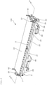
- Fig. 3 is a perspective view showing an outline of the cell culture apparatus according to the present embodiment.
- a culture apparatus 100 is provided with a base 2 having a flat mounting surface 20 for holding the container 1.
- a base 2 having a flat mounting surface 20 for holding the container 1.
- one end on the shorter sides thereof is pivotally supported by a supporting frame 4, and the base 2 can be rotatably moved around the axis.
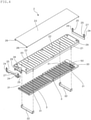
- the base 2 includes a holding member 21 that forms the mounting surface 20 and the partition plates 30 that are disposed below the holding member 21, and the partition plates 30 are provided with a plurality of rectangular partition pieces 3 that are vertically arranged in parallel at regular intervals.
- a plurality of slits 22 are provided in parallel along the longitudinal direction, and the partition pieces 3 arranged vertically on the partition plates 30 can be respectively protruded from the slits 22. Due to such a configuration, the partition pieces 3 that can be protruded from the mounting surface 20 for a prescribed height are embedded in the base 2.
- Fig. 4 shows an exploded perspective view of the base 2 that is provided in the culture apparatus 100 shown in Fig. 3 .
- two pairs of notched parts 31 are formed on the both side surfaces of the langer sides of the partition plate 30, two pairs of notched parts 31 are formed. These notched parts 31 are obtained by notching the opposing parts of the side surfaces with a prescribed width.
- the partition plate 30 can be positioned below the holding member 21. At this time, the shape, dimension, etc.
- each element is appropriately adjusted such that, in the state where the partition plates 30 are floated from the guide member 32 to allow them to be pressed against the holding member 21, the partition pieces 3 are protruded from the mounting surface 20 for a prescribed height and in the state where the partition plates 30 are supported by the guide member 32, the upper surfaces of the partition pieces 3 are flushed with the mounting surface 20 (see Fig. 6 and Fig. 9 ).
- two supporting members 40 having an L-shaped cross section are rotatably attached with the proximal end of the langer side being pivotably supported.
- the supporting member 40 when the langer side is in parallel with the vertical direction, the front end on the langer side thereof contacts the lower surface of the partition plate 30, and as a result, the partition plate 30 is lifted up, and supports the partition plate 30 such that it is pressed against the holding member 21 (see Fig. 6 ).
- the supporting member 40 is rotatably moved such that the langer side thereof is inclined relative to the vertical direction by the weight of the shorter side thereof (see Fig. 7 ).
- the partition plate 30 that is no langer supported by the supporting member 40 is lowered to a position at which it is supported by the guide member 32.
- the partition pieces 3 are accommodated into the base 2, whereby the upper end surfaces of the partition pieces 3 are flushed with the mounting surface 20.
- the pressing plate 23 that presses the upper surface of the container 1 held on the mounting surface 20 to pressurize the inside of the container is attached.
- the pressing plate 23 can be attached in such a manner that, in order to allow the pressing plate 23 to move up and down in accordance with the amount of the content in the container 1 (see Fig. 11 and Fig. 12 ), as shown, at each of the four corners of the base 2, an annular rising piece 25 forming an elongated hole-shaped guide hole 24 is vertically provided, and a pin 26 that is horizontally provided in a protruded manner at the four corners of the pressing plate 23 is inserted into the guide hole 24.
- a thinned part 27 that is formed by notching in a grooveshape is formed.
- the mounting surface 20 can be opened by lifting up the pressing plate 23 obliquely.
- holes 11 bored at the four corners of the container 1 are engaged with fixtures 28 provided at the four corners of the base 2, and the tube 12 connected to the container 1 is fixed to a tube-fixing member 29, whereby the container 1 can be attached to the culture apparatus 100.
- the culture medium M is supplied together with the cells C, thereby allowing a prescribed amount of a content liquid to be stored in the container.
- the pressing plate 23 is returned to its initial position to allow it to be pressed against the container 1, and hooks 41 and 42 are engaged with two sides of the shorter sides of the pressing plate 23, whereby the pressing plate 23 can be fixed at a lower position.
- the upper surface of the container 1 held on the mounting surface 20 is pressed by the pressing plate 23, whereby the inside of the container is pressurized.
- Each of the hooks 41 and 42 to be engaged with the pressing plate 23 is pivotably supported by the supporting frame 4 such that it can be rotatably moved. By moving the hooks 41 and 42 rotatably, engagement with and release from the pressing plate 23 can be conducted. The pressing plate 23 after releasing of the hooks 41 and 42 can be moved upward to a higher position at which the pin 26 contacts the upper edge of the guide hole 24.
- Figs. 6 to 9 are each an explanatory view for explaining the operation of the cell culture apparatus according to the present embodiment, and the cross sections shown in these figures correspond to cross sections taken along the line A-A in Fig. 3 .
- Fig. 6 shows the initial state of the culture apparatus 100. If the container 1 to which the culture medium M is supplied together with the cells C is attached in this state, by the partition pieces 3 that protrude for a prescribed height from the mounting surface 20, the bottom surface of the container 1 is partitioned into a plurality of the compartments 10 (see Fig. 1 ).
- the container 1 is not shown.
- the amount of the culture medium M to be supplied to the container 1 is adjusted to be an amount that allows the inside of the container to be pressurized when the upper surface of the container 1 is pressed by the pressing plate 23 fixed at a lower position.
- the pressing plate 23 is returned to the initial state from the state shown in Fig. 5 and is pressed against the container 1, and the hooks 41 and 42 are engaged with the two sides of the shorter side of the pressing plate 23.
- the inside of the container can be pressurized by pressing by means of the pressing plate 23 the upper surface of the container 1 held on the mounting surface 20.
- the curing culture step is conducted in the way mentioned above. After the curing culture step proceeds and the density of the cells C that have been proliferated is increased to a level that is equal to or higher than a prescribed level and exceeds a range that is suited to culture, the curing culture step is shifted to an expansion culture step.
- the push-up member 5 moves upward, and the base 2 pivotably supported by the supporting frame 4 is moved upward rotatably around the axis.
- the supporting member 40 that supports the partition plate 30 and has an L-shaped cross section, contact with the partition plate 30 is released, and is rotatably moved by the weight of the shorter side such that the langer side is inclined relative to the vertical direction.
- the partition plate 30 that is no langer supported by the supporting member 40 is lowered to a position at which it is supported by the guide member 32, and along with this, the partition pieces 3 are accommodated into the base 2, and the upper end surfaces of the partition pieces 3 are flushed with the mounting surface 20.
- the compartments 10 formed by division by the partition pieces 3 are removed, and the inside of the container becomes one compartment, whereby the culture area is expanded (see Fig. 2 ).
- the hooks 41 and 42 are engaged with the two sides of the shorter sides of the pressing plate 23.
- engagement of the hooks 41 and 42 can be released.
- the base 2 is rotatably moved upward by allowing the push-up member 5 that has moved upward to contact a contact member 50 provided on the shorter side opposite to the side on which the rotation axis of the base 2 is provided.
- a beam-like contact piece 51 is bridged over the contact member 50.
- the push-up member 5 After allowing the base 2 to move rotatably by a predetermined angle, the push-up member 5 is moved downward. As a result, as shown in Fig. 9 , the base 2 is rotatably moved downward and returns to the initial position. At this time, vibration is transmitted to the container 1 held on the mounting surface 20 of the base 2 by the impact generated by receiving of the base 2 by the supporting frame 4. Due to such a configuration, by repeating the rotating operation of the base 2 by moving the push-up member 5 up and down, an operation in which after allowing the container 1 to be moved to a position higher than the initial position, returning the container 1 to the initial position and applying vibration to the container 1 that has returned to the initial position are repeated, whereby the content liquid of the container 1 can be stirred.
- a driving mechanism for moving the push-up member 5 up and down can be configured as a cam mechanism includes a plate cam 5b having a first cam surface 5c with an arcuate contour and a second cam surface 5d with a linear contour, and a receiving plate 5a provided horizontally at the base end of the push-up member 5 as a follower.
- the configuration of the driving mechanism is not limited thereto.
- the curvature of the cam surfaces 5c and 5d, the position of a drive shaft 5e for rotating the plate cam 5b, and the rotational speed of the drive shaft 5e are appropriately set so that the push-up member 5 moves upward as the first cam surface 5c pushes up a receiving plate 5a (see Figs. 10(a) to 10(e) ), the plate cam 5b leaves from the receiving plate 5a when switching to the second cam surface 5d, and then the push-up member 5 falls down (see Figs. 10(f) to 10(h) ), whereby the up-and-down movement of the push-up member 5 is repeated as the plate cam 5b rotates in a fixed direction.
- the driving mechanism is configured as described above, when the base 2 rotates downward to return to its initial position, the base 2rotatably moves as if it falls down, so that an impact is generated when the supporting frame 4 receives the base 2.
- the culture medium M is additionally supplied to the container 1.
- the pressing plate 23 is pushed up by the container 1 of which the amount of the content is increased to have an increased thickness.
- the pin 26 projecting from the pressing plate 23 reaches the upper edge of the guide hole 24, the pressing plate 23 cannot move upward anymore and is fixed at the upper position (see Fig. 12 ).
- the culture apparatus 100 can be shifted from the curing culture step to the expansion culture step by the rotational operation of the base 2.
- the bottom surface of the container 1 that becomes flat by being flattened by the weight of the content liquid is used as a culture surface. If the bottom surface of the container 1 is not sufficiently flattened, wrinkles or slacks are generated on the culture surface, and cells are accumulated in that portion, resulting in excessive cell density. Further, since movement of cells is restricted, it may be concerned that proliferation efficiency of cells is lowered.
- such a place where cells are accumulated may cause cells to remain in the container when recovering cultured cells.
- Patent Document 4 a method is taken in which holes are bored at the four corners of the culture container and fixtures are provided vertically at the four corners of the container mounting table, and the holes of the culture container are engaged with the fixtures of the container mounting table and the culture container is pulled, the culture surface is flattened.
- Fig. 17 shows an example in which the hole 11 provided in the container 1 is engaged with the fixture 28 to pull the container 1. This method is still insufficient to avoid generation of wrinkles or slacks on the bottom surface of the container 1.
- the arrangement and number of the fixtures 28 are not particularly limited, and it suffices that two or more fixtures 28 be oppositely arranged on the periphery of the base 2.
- the fixture 28 be provided vertically at the four corners of the base 2, and that in the case of using a container 1 having a relatively large size, a larger number of fixtures 28 be provided vertically.
- the fixture 28 can be arranged such that one fixture is disposed in the middle of the end part of each of the shorter sides of the base 2, or alternatively, one fixture is disposed in the middle of the end part of one of the shorter sides and two or more fixtures are disposed at the opposing end parts of one of the short sides.
- the hole 11 bored in the container 1 can be provided in accordance with the arrangement and number of the fixture 28 provided in the base 2, and in order to allow the peripheral part of the hole 11 to be engaged with the recess 28a by inserting the fixture 28 into the hole 11, the hole 11 can be provided at a heat-sealed end part region, etc. That is, it suffices that two or more holes 11 be provided at the end part of the container 1 in correspondence with two or more fixtures 28 provided at the peripheral part of the base 2. At this time, it is needless to say that sealing property of the container 1 is required to be prevented from being lowered by provision of the holes 11 in the container 1.
- the shape of the fixture 28 is not particularly limited. For example, it may be substantially columnar, but other shapes such as a substantially rectangular parallelepiped shape may be used. Further, the upper part of the recess 28a may be formed in a dome shape, and the lower part of the recess 28a may be formed into a columnar shape or a prismatic shape.
- the recess 28a be formed circumferentially with respect to the horizontal plane in the fixture 28, but the manner of formation is not limited thereto, and it may be formed in a semi-circumferential shape, an arc shape or the like with respect to the horizontal plane in the outer direction of the base 2. Further, the horizontal cross section of the recess 28a is not limited to a circular shape, and it may be a polygonal shape, a star shape, or the like.
- the position where the recess 28a is formed in the fixture 28 is determined based on the thickness of the container 1 that becomes full by filling the culture solution in the culture container 1 to a full capacity thereof taking into consideration the thickness of the container 1 at the time of being full.
- Fig. 15 shows a state in which, in the fixture 28, the recess 28a is formed at a position, upward from the surface of the base 2, 1/2 of the thickness of the container 1 which is full (almost 1/2 of the liquid depth d), and the peripheral edge portion of the hole 11 of the container 1 is engaged with the recess 28a.
- the end part of the container 1 is held at the height of the recess 28a, and the container 1 can be fixed to the base 2 with the bottom surface of the container 1 being flattened.
- Fig. 16 shows a state in which, in the fixture 28, the recess 28a is formed at a position, upward from the surface of the base 2, 3/4 of the thickness of the container 1 which is full (almost 3/4 of the liquid depth d) and the peripheral edge portion of the hole 11 of the container 1 is engaged with the recess 28a.
- the bottom surface of the container 1 can be flattened.
- the recess 28a is at a position upward from the surface of the base 2 that is slightly higher than the thickness of the container 1 that is full.
- a position where the recess 28a is formed in the fixture 28 be set, upward from the surface of the base 2, such that it corresponds to 1/2 to 3/2, more preferably 1/2 to 1, further preferably 1/2 to 3/4, of the thickness of the container 1 which is full.
- the bottom surface of the container 1 after the culture step is shifted to the expansion culture step can be kept in a flattened state more reliably, and the culture surface can be in a state where no wrinkles or slacks are formed. As a result, the culture area of the container 1 can be maximized.
- the bottom surface of the container 1 is partially raised and separated into plural compartments 10 by holding the container 1 on the base 2 in which the partition pieces 3 that can be protruded from the mounting surface 20 for a prescribed height are embedded in a state that the partition pieces 3 are protruded.
- the cell culture method according to the present invention can be implemented without being limited thereto.
- a plurality of rod-like members may be arranged side by side on the mounting surface 20, and the container 1 is held thereon.
- the bottom surface of the container 1 is partially raised by pushing up by the rod-like member, and as a result, the bottom surface is separated into plural compartments 10. If such rod-like members are drawn, the bottom surface of the container 1 is flattened by the weight of the content liquid, whereby the culture area of the container is expanded.
- the pressing plate 23 is attached by providing vertically annular rising sections 25 forming an elongated hole-shaped guide hole 24 at the four sides of the base 2, and inserting the pin 26 that is horizontally projected at the four corners of the pressing plate 23.
- the manner of attachment of the pressing plate 23 is not limited thereto. It suffices that the pressing plate 23 be attached such that it can be moved vertically in accordance with the amount of the content of the container 1. For example, it can be attached as shown in Fig. 13 and Fig. 14 .
- Fig. 13 and Fig. 14 two pairs of rising sections 25a having elongated hole-shaped guide holes 24a are provided vertically at opposing positions on the longer sides of the base 2 so as to form a pair, and the pressing plate 23 is attached so that it can be moved up and down through a supporting rod 26a disposed between each of the rising sections 25a forming a pair.
- the hook F is engaged with the supporting rod 26a inserted into the guide hole 24a to suppress the upward movement of the pressing plate 23, whereby the upper surface of the container 1 in which a content is filled in a prescribed amount is pressed by the pressing plate 23 fixed at a lower position, thus enabling the inside of the container to be pressurized (see Fig. 13 ).
- the pressing plate 23 In the expansion culture step, by releasing the engagement of the hook F, the pressing plate 23 can be moved upward. When the supporting rod 26a reaches the upper edge of the guide hole 24a, the pressing plate 23 cannot be moved to a position higher than the upper edge, and fixed at an upper position. Due to such a configuration, the upper surface of the container 1 of which the content amount is increased to have an increased thickness by additional supply of a culture medium M is pressed by the pressing plate 23, thus enabling the inside of the container to be pressurized (see Fig. 14 ).
- the hook F is allowed to move rotatably by its own weight by the inclination of the base 2.
- the present invention can be preferably used in gene therapy, immunotherapy, regenerative therapy, production of antibody medicines, etc. where cells are cultured aseptically and easily in a closed system by using a cell culture apparatus.
Landscapes
- Health & Medical Sciences (AREA)
- Engineering & Computer Science (AREA)
- Life Sciences & Earth Sciences (AREA)
- Chemical & Material Sciences (AREA)
- Wood Science & Technology (AREA)
- Organic Chemistry (AREA)
- Bioinformatics & Cheminformatics (AREA)
- Zoology (AREA)
- Biomedical Technology (AREA)
- Biotechnology (AREA)
- Genetics & Genomics (AREA)
- Biochemistry (AREA)
- Microbiology (AREA)
- General Engineering & Computer Science (AREA)
- General Health & Medical Sciences (AREA)
- Sustainable Development (AREA)
- Cell Biology (AREA)
- Clinical Laboratory Science (AREA)
- Immunology (AREA)
- Hematology (AREA)
- Developmental Biology & Embryology (AREA)
- Tropical Medicine & Parasitology (AREA)
- Medicinal Chemistry (AREA)
- Virology (AREA)
- Transplantation (AREA)
- Rheumatology (AREA)
- Dermatology (AREA)
- Mechanical Engineering (AREA)
- Apparatus Associated With Microorganisms And Enzymes (AREA)
Claims (16)
- Verfahren zur Kultivierung von Zellen, bei dem ein Kulturmedium zusammen mit Zellen in einen aus einem flexiblen Material gebildeten Behälter (1) zugeführt wird, um dadurch eine Zellkultur durchzuführen, wobei,eine Bodenfläche des Behälters (1) teilweise angehoben wird, um in eine Vielzahl von Fächern (10) durch Anheben von Trennwandstücken unterteilt zu werden,die Zellen in jedem Fach (10) kultiviert werden, undzu gegebener Zeit die Fächer (10) entfernt werden, um eine Kulturfläche in dem Behälter (1) zu vergrössern.
- Verfahren zur Kultivierung von Zellen nach Anspruch 1, dadurch gekennzeichnet, dass der Behälter (1) auf einer Basis (2) gehalten wird, die eine ebene Montagefläche (20) aufweist und in der Trennwandstücke (3) eingebettet sind, die über eine vorgegebene Höhe aus der Montagefläche (20) herausragen können, und
die Bodenfläche des Behälters (1) durch über die Montagefläche (20) herausragende Trennwandstücke (3) teilweise angehoben wird, um dadurch die Bodenfläche in eine Vielzahl von Fächern (10) zu unterteilen. - Verfahren zur Kultivierung von Zellen nach Anspruch 2, wobei die Trennwandstücke (3) in der Basis (2) untergebracht sind und die oberen Endflächen der Trennwandstücke mit der Montagefläche (20) bündig sind, um dadurch die Fächer (10) zu entfernen.
- Verfahren zur Kultivierung von Zellen nach einem der Ansprüche 1 bis 3, wobei,wenn die Zellkultur durch Vergrösserung der Kulturfläche im Behälter (1) durch Entfernen der Fächer (10) fortgesetzt wird,nach dem Bewegen des Behälters (1) in eine Position, die höher als eine Ausgangsposition ist, der Behälter (1) in die Ausgangsposition zurückgebracht wird und eine Vibration auf den in die Ausgangsposition zurückgebrachten Behälter (1) ausgeübt wird, um dadurch eine Inhaltsflüssigkeit in dem Behälter (1) zu rühren.
- Verfahren zur Kultivierung von Zellen nach einem der Ansprüche 1 bis 4, wobei,eine Druckplatte (23), die so angebracht ist, dass sie nach oben und nach unten bewegt werden kann, in einer unteren Position fixiert wird, und der Behälter (1), in dem die Menge eines Inhalts auf ein vorgeschriebenes Niveau eingestellt ist, durch die Druckplatte (23) gepresst wird, wodurch eine Zellkultivierung durchgeführt wird, wobei das Innere des Behälters (1) unter Druck gesetzt wird,zu gegebener Zeit das Kulturmedium zusätzlich dem Behälter (1) zugeführt wird und die Druckplatte (23) in einer oberen Position fixiert wird, undder Behälter (1), dessen Inhalt vergrössert wird, durch die Druckplatte (23) gepresst wird, wodurch die Zellkultivierung mit dem unter Druck stehenden Inneren des Behälters (1) fortgesetzt wird.
- Zellkultivierungsvorrichtung zur Durchführung einer Zellkultivierung, bei der ein Kulturmedium zusammen mit Zellen in einen aus einem flexiblen Material gebildeten Behälter (1) zugeführt wird, umfassendeine Basis (2) mit einer flachen Montagefläche (20), die den Behälter (1) hält,Trennwandstücke (3), die in die Basis (2) eingebettet sind, so dass die Trennwandstücke (3) über eine vorgegebene Höhe aus der Montagefläche (20) herausragen können, undwenn die Trennwandstücke (3) in der Basis (2) untergebracht sind, die oberen Endflächen der Trennwandstücke (3) mit der Montagefläche (20) bündig sind.
- Zellkultivierungsvorrichtung nach Anspruch 6, wobei die Basis (2) mit einem Halteelement (21), das die Montagefläche (20) bildet, und einer Trennwandplatte (30) versehen ist, auf der eine Vielzahl der Trennwandstücke (3) parallel zueinander mit einem vorgeschriebenen Abstand angeordnet sind.
- Zellkultivierungsvorrichtung nach Anspruch 6 oder 7, wobei ein Ende auf kürzeren Seiten der Basis (2) schwenkbar von einem Stützrahmen (4) getragen wird, so dass die Basis (2) um eine Achse aufwärts und abwärts drehbar bewegt werden kann, und aufgrund des Drehbetriebs der Basis (2), nachdem der Behälter (1) in eine Position bewegt wurde, die höher als eine Ausgangsposition ist, der Behälter (1) in die Ausgangsposition zurückgebracht wird und eine Inhaltsflüssigkeit in dem Behälter (1) durch Einbringen einer Vibration auf den in die Ausgangsposition zurückgebrachten Behälter (1) gerührt wird.
- Zellkultivierungsvorrichtung nach einem der Ansprüche 6 bis 8, wobei eine Druckplatte (23) zur Druckbeaufschlagung des Inneren des Behälters (1) durch Drücken des auf der Montagefläche (20) gehaltenen Behälters (1) so angebracht ist, dass sie in Abhängigkeit von der Menge eines Inhalts im Behälter (1) auf und ab bewegt werden kann.
- Zellkultivierungsvorrichtung nach Anspruch 9, wobei an jeder der vier Ecken der Basis (2) ringförmige, ansteigende Stücke mit jeweils einem länglichen Führungsloch (24) vertikal vorgesehen sind und die Druckplatte (23) durch Einführen eines an jeder der vier Ecken der Druckplatte (23) vorgesehenen Stifts (26) in das Führungsloch (24) so an der Basis (2) befestigt ist, dass sie nach oben und unten bewegt werden kann, und wobei ein Haken (41, 42) vorgesehen ist, der mit der Druckplatte (23) in Eingriff steht und die Druckplatte (23) in einer vorgegebenen Position fixiert.
- Zellkultivierungsvorrichtung nach Anspruch 10, wobei die Basis (2) derart an einem Tragrahmen (4) verschwenkbar gelagert ist, dass sie drehbar bewegt werden kann, und durch die Drehbewegung der Basis (2) der Eingriff des Hakens (41, 42) gelöst wird.
- Zellkultivierungsvorrichtung nach einem der Ansprüche 6 bis 11, wobei zwei oder mehr Halterungen (28), die den Behälter (1) fixieren, vertikal so vorgesehen sind, dass sie sich am Umfang der Basis (2) gegenüberliegen, und in der Halterung (28) eine Ausnehmung (28a) ausgebildet ist.
- Zellkultivierungsvorrichtung nach Anspruch 12, wobei die Ausnehmung (28a) in der Halterung (28) an einer Position oberhalb der Oberfläche der Basis (2) ausgebildet ist, die der Hälfte bis 3/2 der Dicke des gefüllten Behälters (1) entspricht.
- Zellkultivierungsvorrichtung nach Anspruch 12 oder 13, wobei die Ausnehmung (28a) in der Halterung (28) in Umfangsrichtung relativ zur horizontalen Ebene ausgebildet ist.
- Zellkultivierungsvorrichtung nach einem der Ansprüche 12 bis 14, wobei die Halterung (28) an jeder der vier Ecken der Basis (2) vertikal angeordnet ist.
- Zellkultivierungsvorrichtung nach einem der Ansprüche 12 bis 15, wobei zwei oder mehr Löcher (11) an den Endteilen des Behälters (1) so vorgesehen sind, dass sie den Halterungen (28) entsprechend, und die Halterungen (28) in die Löcher (11) eingesetzt sind, um zu ermöglichen, dass die peripheren Teile der Löcher (11) mit der Ausnehmung (28a) in Eingriff kommen.
Applications Claiming Priority (4)
| Application Number | Priority Date | Filing Date | Title |
|---|---|---|---|
| JP2015017823A JP6609931B2 (ja) | 2015-01-30 | 2015-01-30 | 細胞培養方法、及び細胞培養装置 |
| JP2015017824A JP2016140296A (ja) | 2015-01-30 | 2015-01-30 | 細胞培養装置、及び細胞培養方法 |
| JP2015017827A JP2016140299A (ja) | 2015-01-30 | 2015-01-30 | 培養バッグ固定台、及び培養バッグ固定台の使用方法 |
| PCT/JP2016/000002 WO2016121292A1 (ja) | 2015-01-30 | 2016-01-04 | 細胞培養方法、及び細胞培養装置 |
Publications (3)
| Publication Number | Publication Date |
|---|---|
| EP3252140A1 EP3252140A1 (de) | 2017-12-06 |
| EP3252140A4 EP3252140A4 (de) | 2018-09-26 |
| EP3252140B1 true EP3252140B1 (de) | 2022-03-02 |
Family
ID=56542921
Family Applications (1)
| Application Number | Title | Priority Date | Filing Date |
|---|---|---|---|
| EP16742901.8A Active EP3252140B1 (de) | 2015-01-30 | 2016-01-04 | Zellkulturverfahren und zellkulturvorrichtung |
Country Status (6)
| Country | Link |
|---|---|
| US (2) | US10731122B2 (de) |
| EP (1) | EP3252140B1 (de) |
| KR (1) | KR101984074B1 (de) |
| CN (1) | CN107208030B (de) |
| TW (1) | TWI691594B (de) |
| WO (1) | WO2016121292A1 (de) |
Families Citing this family (8)
| Publication number | Priority date | Publication date | Assignee | Title |
|---|---|---|---|---|
| EP3532598B1 (de) | 2016-10-28 | 2020-09-09 | Global Life Sciences Solutions USA LLC | Bioreaktorschale |
| JP6341263B1 (ja) * | 2016-12-08 | 2018-06-13 | 東洋製罐グループホールディングス株式会社 | 細胞培養装置 |
| JP7035343B2 (ja) | 2017-06-15 | 2022-03-15 | 東洋製罐グループホールディングス株式会社 | 細胞培養方法及び装置 |
| JP7102734B2 (ja) * | 2018-01-09 | 2022-07-20 | 東洋製罐グループホールディングス株式会社 | 細胞培養方法及び装置 |
| JP7348586B2 (ja) * | 2019-01-18 | 2023-09-21 | 東洋製罐グループホールディングス株式会社 | 培養容器、培養方法、及び培養装置 |
| CN114657064A (zh) * | 2020-12-23 | 2022-06-24 | 基亚生物科技股份有限公司 | 自动化细胞培养装置 |
| JP2023074202A (ja) | 2021-11-17 | 2023-05-29 | 株式会社リコー | 収容体、レーザー加工装置、及びレーザー加工方法 |
| WO2024108358A1 (zh) * | 2022-11-21 | 2024-05-30 | 深圳先进技术研究院 | 一种组织样品推进器 |
Family Cites Families (27)
| Publication number | Priority date | Publication date | Assignee | Title |
|---|---|---|---|---|
| JPH0620524B2 (ja) * | 1987-07-11 | 1994-03-23 | 川澄化学工業株式会社 | 液体及び/又は固体入り容器の揺動装置 |
| JPH0353679Y2 (de) | 1987-03-31 | 1991-11-25 | ||
| DE3788026T2 (de) | 1986-08-27 | 1994-04-21 | Kawasumi Lab Inc | Verfahren und Vorrichtung zur Kultivierung von Zellen. |
| US5017490A (en) * | 1989-03-10 | 1991-05-21 | Baxter International Inc. | Method for in vitro reproduction and growth of cells in culture medium |
| JP2000125848A (ja) | 1998-10-19 | 2000-05-09 | Agriculture Forestry & Fisheries Technical Information Society | 細胞培養用具及び前記細胞培養用具を用いる簡易細胞培養方法 |
| JP2004089136A (ja) * | 2002-09-03 | 2004-03-25 | Olympus Corp | 培養容器 |
| US20040214313A1 (en) * | 2003-04-28 | 2004-10-28 | Weihua Zhang | Cell interaction culture system and uses thereof |
| JP4806761B2 (ja) * | 2005-05-24 | 2011-11-02 | 独立行政法人国立がん研究センター | 培養用トレイ |
| CN101421387B (zh) | 2006-04-13 | 2012-07-18 | 大学共同利用机关法人信息与系统研究机构 | 多孔培养装置及使用该装置的分析方法 |
| CN105670928A (zh) * | 2007-04-27 | 2016-06-15 | 东洋制罐集团控股株式会社 | 细胞培养装置、细胞培养体系及细胞培养方法 |
| CN101809142A (zh) | 2007-09-26 | 2010-08-18 | 通用电气医疗集团生物科学生物方法公司 | 三维可用后即弃生物反应器 |
| WO2009123173A1 (ja) | 2008-04-01 | 2009-10-08 | 東洋製罐株式会社 | 培養容器、培養方法、及び培養装置 |
| US20110238029A1 (en) | 2008-11-28 | 2011-09-29 | Terumo Kabushiki Kaisha | Blood bag system and cassette |
| US8460267B2 (en) | 2008-11-28 | 2013-06-11 | Terumo Kabushiki Kaisha | Blood bag system and cassette |
| KR101828916B1 (ko) | 2009-03-09 | 2018-03-29 | 도요세이칸 그룹 홀딩스 가부시키가이샤 | 세포 배양 방법, 세포 배양 장치, 용기 내의 계수 대상물의 계수 방법, 및 계수용 장치 |
| JP2011109933A (ja) * | 2009-11-24 | 2011-06-09 | Nikon Corp | 培養容器アダプタ |
| JP2011241159A (ja) | 2010-05-17 | 2011-12-01 | Toyo Shinyaku Co Ltd | 美白剤 |
| JP5740841B2 (ja) * | 2010-05-19 | 2015-07-01 | 東洋製罐グループホールディングス株式会社 | 細胞培養方法、細胞培養装置、及び細胞培養装置の制御方法 |
| WO2012032761A1 (ja) | 2010-09-06 | 2012-03-15 | 東洋製罐株式会社 | 多層フィルム、及び細胞培養容器 |
| JP5786444B2 (ja) * | 2011-05-17 | 2015-09-30 | 東洋製罐グループホールディングス株式会社 | 細胞培養方法、及び細胞培養システム |
| US20140302597A1 (en) | 2011-12-14 | 2014-10-09 | Hitachi, Ltd. | Cell culture container, and automated cell subculture device and cell subculture method using same |
| EP2639294A1 (de) * | 2012-03-15 | 2013-09-18 | CellProthera | Automat und automatisiertes Verfahren zur Herstellung von Zellkulturen |
| JP6142142B2 (ja) | 2012-04-10 | 2017-06-07 | 株式会社リンフォテック | メモリーt細胞を主成分とするリンパ球細胞群の製造方法 |
| KR20160103135A (ko) * | 2014-03-07 | 2016-08-31 | 도요세이칸 그룹 홀딩스 가부시키가이샤 | 세포 배양 방법 및 세포 배양 장치 |
| JP2015188391A (ja) * | 2014-03-28 | 2015-11-02 | 東洋製罐グループホールディングス株式会社 | 細胞培養方法、及び細胞培養システム |
| JP2015188390A (ja) * | 2014-03-28 | 2015-11-02 | 東洋製罐グループホールディングス株式会社 | 細胞培養方法、及び細胞培養システム |
| JP6424447B2 (ja) | 2014-03-28 | 2018-11-21 | 東洋製罐グループホールディングス株式会社 | 細胞培養方法、及び細胞培養システム |
-
2016
- 2016-01-04 CN CN201680006996.4A patent/CN107208030B/zh active Active
- 2016-01-04 EP EP16742901.8A patent/EP3252140B1/de active Active
- 2016-01-04 US US15/542,978 patent/US10731122B2/en active Active
- 2016-01-04 KR KR1020177019751A patent/KR101984074B1/ko active Active
- 2016-01-04 WO PCT/JP2016/000002 patent/WO2016121292A1/ja not_active Ceased
- 2016-01-08 TW TW105100536A patent/TWI691594B/zh active
-
2020
- 2020-06-18 US US16/904,690 patent/US11390842B2/en active Active
Also Published As
| Publication number | Publication date |
|---|---|
| TWI691594B (zh) | 2020-04-21 |
| US10731122B2 (en) | 2020-08-04 |
| US20200318057A1 (en) | 2020-10-08 |
| EP3252140A1 (de) | 2017-12-06 |
| CN107208030B (zh) | 2020-12-18 |
| KR101984074B1 (ko) | 2019-05-30 |
| TW201639952A (zh) | 2016-11-16 |
| EP3252140A4 (de) | 2018-09-26 |
| US11390842B2 (en) | 2022-07-19 |
| WO2016121292A1 (ja) | 2016-08-04 |
| CN107208030A (zh) | 2017-09-26 |
| US20170362559A1 (en) | 2017-12-21 |
| KR20170093245A (ko) | 2017-08-14 |
Similar Documents
| Publication | Publication Date | Title |
|---|---|---|
| US11390842B2 (en) | Cell culture method and cell culture apparatus | |
| KR101925778B1 (ko) | 세포 배양 방법 및 세포 배양 시스템 | |
| KR101489014B1 (ko) | 세포배양장치, 세포배양시스템 및 세포배양방법 | |
| JP6427872B2 (ja) | 細胞培養方法、及び細胞培養装置 | |
| JP7102734B2 (ja) | 細胞培養方法及び装置 | |
| JP5740841B2 (ja) | 細胞培養方法、細胞培養装置、及び細胞培養装置の制御方法 | |
| JP2015188391A (ja) | 細胞培養方法、及び細胞培養システム | |
| JP2004089136A (ja) | 培養容器 | |
| JP6609931B2 (ja) | 細胞培養方法、及び細胞培養装置 | |
| JP2010233563A (ja) | 細胞培養方法、及び細胞培養装置 | |
| JP2016140296A (ja) | 細胞培養装置、及び細胞培養方法 | |
| JP2016140299A (ja) | 培養バッグ固定台、及び培養バッグ固定台の使用方法 | |
| JP2015188390A (ja) | 細胞培養方法、及び細胞培養システム | |
| CN115717098B (zh) | 一种冻土微生物培养设备 | |
| JP2015116151A (ja) | 細胞培養装置、及び細胞培養方法 | |
| CN110438006A (zh) | 一种贴壁单细胞分双层培养装置 | |
| US7588932B2 (en) | Insert device for culturing cells | |
| WO2024014317A1 (ja) | 細胞培養装置、細胞培養システム、及び細胞培養方法 | |
| JP6341263B1 (ja) | 細胞培養装置 | |
| JP2018068191A (ja) | 細胞移動方法、培養液排出方法、及び細胞移動装置 | |
| JP2015116152A (ja) | 培養容器、及びリンパ球の培養方法 | |
| JP2015050963A (ja) | 樹状細胞の調製方法 |
Legal Events
| Date | Code | Title | Description |
|---|---|---|---|
| STAA | Information on the status of an ep patent application or granted ep patent |
Free format text: STATUS: THE INTERNATIONAL PUBLICATION HAS BEEN MADE |
|
| PUAI | Public reference made under article 153(3) epc to a published international application that has entered the european phase |
Free format text: ORIGINAL CODE: 0009012 |
|
| STAA | Information on the status of an ep patent application or granted ep patent |
Free format text: STATUS: REQUEST FOR EXAMINATION WAS MADE |
|
| 17P | Request for examination filed |
Effective date: 20170704 |
|
| AK | Designated contracting states |
Kind code of ref document: A1 Designated state(s): AL AT BE BG CH CY CZ DE DK EE ES FI FR GB GR HR HU IE IS IT LI LT LU LV MC MK MT NL NO PL PT RO RS SE SI SK SM TR |
|
| AX | Request for extension of the european patent |
Extension state: BA ME |
|
| DAV | Request for validation of the european patent (deleted) | ||
| DAX | Request for extension of the european patent (deleted) | ||
| RIC1 | Information provided on ipc code assigned before grant |
Ipc: C12N 5/0775 20100101ALI20180816BHEP Ipc: C12M 3/00 20060101ALI20180816BHEP Ipc: C12N 5/074 20100101ALI20180816BHEP Ipc: C12N 5/00 20060101ALI20180816BHEP Ipc: C12N 5/078 20100101ALI20180816BHEP Ipc: C12M 1/42 20060101ALI20180816BHEP Ipc: C12M 1/00 20060101ALI20180816BHEP Ipc: C12N 1/00 20060101AFI20180816BHEP Ipc: C12M 1/12 20060101ALI20180816BHEP Ipc: C12N 5/071 20100101ALI20180816BHEP |
|
| A4 | Supplementary search report drawn up and despatched |
Effective date: 20180824 |
|
| GRAP | Despatch of communication of intention to grant a patent |
Free format text: ORIGINAL CODE: EPIDOSNIGR1 |
|
| STAA | Information on the status of an ep patent application or granted ep patent |
Free format text: STATUS: GRANT OF PATENT IS INTENDED |
|
| INTG | Intention to grant announced |
Effective date: 20210624 |
|
| GRAJ | Information related to disapproval of communication of intention to grant by the applicant or resumption of examination proceedings by the epo deleted |
Free format text: ORIGINAL CODE: EPIDOSDIGR1 |
|
| STAA | Information on the status of an ep patent application or granted ep patent |
Free format text: STATUS: REQUEST FOR EXAMINATION WAS MADE |
|
| INTC | Intention to grant announced (deleted) | ||
| GRAP | Despatch of communication of intention to grant a patent |
Free format text: ORIGINAL CODE: EPIDOSNIGR1 |
|
| STAA | Information on the status of an ep patent application or granted ep patent |
Free format text: STATUS: GRANT OF PATENT IS INTENDED |
|
| INTG | Intention to grant announced |
Effective date: 20211207 |
|
| GRAS | Grant fee paid |
Free format text: ORIGINAL CODE: EPIDOSNIGR3 |
|
| GRAA | (expected) grant |
Free format text: ORIGINAL CODE: 0009210 |
|
| STAA | Information on the status of an ep patent application or granted ep patent |
Free format text: STATUS: THE PATENT HAS BEEN GRANTED |
|
| AK | Designated contracting states |
Kind code of ref document: B1 Designated state(s): AL AT BE BG CH CY CZ DE DK EE ES FI FR GB GR HR HU IE IS IT LI LT LU LV MC MK MT NL NO PL PT RO RS SE SI SK SM TR |
|
| REG | Reference to a national code |
Ref country code: GB Ref legal event code: FG4D |
|
| REG | Reference to a national code |
Ref country code: CH Ref legal event code: EP Ref country code: AT Ref legal event code: REF Ref document number: 1472251 Country of ref document: AT Kind code of ref document: T Effective date: 20220315 |
|
| REG | Reference to a national code |
Ref country code: DE Ref legal event code: R096 Ref document number: 602016069593 Country of ref document: DE |
|
| REG | Reference to a national code |
Ref country code: IE Ref legal event code: FG4D |
|
| REG | Reference to a national code |
Ref country code: LT Ref legal event code: MG9D |
|
| REG | Reference to a national code |
Ref country code: NL Ref legal event code: MP Effective date: 20220302 |
|
| PG25 | Lapsed in a contracting state [announced via postgrant information from national office to epo] |
Ref country code: SE Free format text: LAPSE BECAUSE OF FAILURE TO SUBMIT A TRANSLATION OF THE DESCRIPTION OR TO PAY THE FEE WITHIN THE PRESCRIBED TIME-LIMIT Effective date: 20220302 Ref country code: RS Free format text: LAPSE BECAUSE OF FAILURE TO SUBMIT A TRANSLATION OF THE DESCRIPTION OR TO PAY THE FEE WITHIN THE PRESCRIBED TIME-LIMIT Effective date: 20220302 Ref country code: NO Free format text: LAPSE BECAUSE OF FAILURE TO SUBMIT A TRANSLATION OF THE DESCRIPTION OR TO PAY THE FEE WITHIN THE PRESCRIBED TIME-LIMIT Effective date: 20220602 Ref country code: LT Free format text: LAPSE BECAUSE OF FAILURE TO SUBMIT A TRANSLATION OF THE DESCRIPTION OR TO PAY THE FEE WITHIN THE PRESCRIBED TIME-LIMIT Effective date: 20220302 Ref country code: HR Free format text: LAPSE BECAUSE OF FAILURE TO SUBMIT A TRANSLATION OF THE DESCRIPTION OR TO PAY THE FEE WITHIN THE PRESCRIBED TIME-LIMIT Effective date: 20220302 Ref country code: ES Free format text: LAPSE BECAUSE OF FAILURE TO SUBMIT A TRANSLATION OF THE DESCRIPTION OR TO PAY THE FEE WITHIN THE PRESCRIBED TIME-LIMIT Effective date: 20220302 Ref country code: BG Free format text: LAPSE BECAUSE OF FAILURE TO SUBMIT A TRANSLATION OF THE DESCRIPTION OR TO PAY THE FEE WITHIN THE PRESCRIBED TIME-LIMIT Effective date: 20220602 |
|
| REG | Reference to a national code |
Ref country code: AT Ref legal event code: MK05 Ref document number: 1472251 Country of ref document: AT Kind code of ref document: T Effective date: 20220302 |
|
| PG25 | Lapsed in a contracting state [announced via postgrant information from national office to epo] |
Ref country code: PL Free format text: LAPSE BECAUSE OF FAILURE TO SUBMIT A TRANSLATION OF THE DESCRIPTION OR TO PAY THE FEE WITHIN THE PRESCRIBED TIME-LIMIT Effective date: 20220302 Ref country code: LV Free format text: LAPSE BECAUSE OF FAILURE TO SUBMIT A TRANSLATION OF THE DESCRIPTION OR TO PAY THE FEE WITHIN THE PRESCRIBED TIME-LIMIT Effective date: 20220302 Ref country code: GR Free format text: LAPSE BECAUSE OF FAILURE TO SUBMIT A TRANSLATION OF THE DESCRIPTION OR TO PAY THE FEE WITHIN THE PRESCRIBED TIME-LIMIT Effective date: 20220603 Ref country code: FI Free format text: LAPSE BECAUSE OF FAILURE TO SUBMIT A TRANSLATION OF THE DESCRIPTION OR TO PAY THE FEE WITHIN THE PRESCRIBED TIME-LIMIT Effective date: 20220302 |
|
| PG25 | Lapsed in a contracting state [announced via postgrant information from national office to epo] |
Ref country code: NL Free format text: LAPSE BECAUSE OF FAILURE TO SUBMIT A TRANSLATION OF THE DESCRIPTION OR TO PAY THE FEE WITHIN THE PRESCRIBED TIME-LIMIT Effective date: 20220302 |
|
| PG25 | Lapsed in a contracting state [announced via postgrant information from national office to epo] |
Ref country code: SM Free format text: LAPSE BECAUSE OF FAILURE TO SUBMIT A TRANSLATION OF THE DESCRIPTION OR TO PAY THE FEE WITHIN THE PRESCRIBED TIME-LIMIT Effective date: 20220302 Ref country code: SK Free format text: LAPSE BECAUSE OF FAILURE TO SUBMIT A TRANSLATION OF THE DESCRIPTION OR TO PAY THE FEE WITHIN THE PRESCRIBED TIME-LIMIT Effective date: 20220302 Ref country code: RO Free format text: LAPSE BECAUSE OF FAILURE TO SUBMIT A TRANSLATION OF THE DESCRIPTION OR TO PAY THE FEE WITHIN THE PRESCRIBED TIME-LIMIT Effective date: 20220302 Ref country code: PT Free format text: LAPSE BECAUSE OF FAILURE TO SUBMIT A TRANSLATION OF THE DESCRIPTION OR TO PAY THE FEE WITHIN THE PRESCRIBED TIME-LIMIT Effective date: 20220704 Ref country code: EE Free format text: LAPSE BECAUSE OF FAILURE TO SUBMIT A TRANSLATION OF THE DESCRIPTION OR TO PAY THE FEE WITHIN THE PRESCRIBED TIME-LIMIT Effective date: 20220302 Ref country code: CZ Free format text: LAPSE BECAUSE OF FAILURE TO SUBMIT A TRANSLATION OF THE DESCRIPTION OR TO PAY THE FEE WITHIN THE PRESCRIBED TIME-LIMIT Effective date: 20220302 Ref country code: AT Free format text: LAPSE BECAUSE OF FAILURE TO SUBMIT A TRANSLATION OF THE DESCRIPTION OR TO PAY THE FEE WITHIN THE PRESCRIBED TIME-LIMIT Effective date: 20220302 |
|
| PG25 | Lapsed in a contracting state [announced via postgrant information from national office to epo] |
Ref country code: IS Free format text: LAPSE BECAUSE OF FAILURE TO SUBMIT A TRANSLATION OF THE DESCRIPTION OR TO PAY THE FEE WITHIN THE PRESCRIBED TIME-LIMIT Effective date: 20220702 Ref country code: AL Free format text: LAPSE BECAUSE OF FAILURE TO SUBMIT A TRANSLATION OF THE DESCRIPTION OR TO PAY THE FEE WITHIN THE PRESCRIBED TIME-LIMIT Effective date: 20220302 |
|
| REG | Reference to a national code |
Ref country code: DE Ref legal event code: R097 Ref document number: 602016069593 Country of ref document: DE |
|
| PLBE | No opposition filed within time limit |
Free format text: ORIGINAL CODE: 0009261 |
|
| STAA | Information on the status of an ep patent application or granted ep patent |
Free format text: STATUS: NO OPPOSITION FILED WITHIN TIME LIMIT |
|
| PG25 | Lapsed in a contracting state [announced via postgrant information from national office to epo] |
Ref country code: DK Free format text: LAPSE BECAUSE OF FAILURE TO SUBMIT A TRANSLATION OF THE DESCRIPTION OR TO PAY THE FEE WITHIN THE PRESCRIBED TIME-LIMIT Effective date: 20220302 |
|
| 26N | No opposition filed |
Effective date: 20221205 |
|
| PG25 | Lapsed in a contracting state [announced via postgrant information from national office to epo] |
Ref country code: SI Free format text: LAPSE BECAUSE OF FAILURE TO SUBMIT A TRANSLATION OF THE DESCRIPTION OR TO PAY THE FEE WITHIN THE PRESCRIBED TIME-LIMIT Effective date: 20220302 |
|
| PG25 | Lapsed in a contracting state [announced via postgrant information from national office to epo] |
Ref country code: IT Free format text: LAPSE BECAUSE OF FAILURE TO SUBMIT A TRANSLATION OF THE DESCRIPTION OR TO PAY THE FEE WITHIN THE PRESCRIBED TIME-LIMIT Effective date: 20220302 |
|
| REG | Reference to a national code |
Ref country code: CH Ref legal event code: PL |
|
| PG25 | Lapsed in a contracting state [announced via postgrant information from national office to epo] |
Ref country code: LU Free format text: LAPSE BECAUSE OF NON-PAYMENT OF DUE FEES Effective date: 20230104 |
|
| REG | Reference to a national code |
Ref country code: BE Ref legal event code: MM Effective date: 20230131 |
|
| PG25 | Lapsed in a contracting state [announced via postgrant information from national office to epo] |
Ref country code: LI Free format text: LAPSE BECAUSE OF NON-PAYMENT OF DUE FEES Effective date: 20230131 Ref country code: CH Free format text: LAPSE BECAUSE OF NON-PAYMENT OF DUE FEES Effective date: 20230131 |
|
| PG25 | Lapsed in a contracting state [announced via postgrant information from national office to epo] |
Ref country code: BE Free format text: LAPSE BECAUSE OF NON-PAYMENT OF DUE FEES Effective date: 20230131 |
|
| PG25 | Lapsed in a contracting state [announced via postgrant information from national office to epo] |
Ref country code: IE Free format text: LAPSE BECAUSE OF NON-PAYMENT OF DUE FEES Effective date: 20230104 |
|
| PG25 | Lapsed in a contracting state [announced via postgrant information from national office to epo] |
Ref country code: MC Free format text: LAPSE BECAUSE OF FAILURE TO SUBMIT A TRANSLATION OF THE DESCRIPTION OR TO PAY THE FEE WITHIN THE PRESCRIBED TIME-LIMIT Effective date: 20220302 |
|
| PG25 | Lapsed in a contracting state [announced via postgrant information from national office to epo] |
Ref country code: MC Free format text: LAPSE BECAUSE OF FAILURE TO SUBMIT A TRANSLATION OF THE DESCRIPTION OR TO PAY THE FEE WITHIN THE PRESCRIBED TIME-LIMIT Effective date: 20220302 |
|
| PGFP | Annual fee paid to national office [announced via postgrant information from national office to epo] |
Ref country code: DE Payment date: 20250121 Year of fee payment: 10 |
|
| PGFP | Annual fee paid to national office [announced via postgrant information from national office to epo] |
Ref country code: FR Payment date: 20250127 Year of fee payment: 10 |
|
| PGFP | Annual fee paid to national office [announced via postgrant information from national office to epo] |
Ref country code: GB Payment date: 20250128 Year of fee payment: 10 |
|
| PG25 | Lapsed in a contracting state [announced via postgrant information from national office to epo] |
Ref country code: CY Free format text: LAPSE BECAUSE OF FAILURE TO SUBMIT A TRANSLATION OF THE DESCRIPTION OR TO PAY THE FEE WITHIN THE PRESCRIBED TIME-LIMIT; INVALID AB INITIO Effective date: 20160104 |
|
| PG25 | Lapsed in a contracting state [announced via postgrant information from national office to epo] |
Ref country code: HU Free format text: LAPSE BECAUSE OF FAILURE TO SUBMIT A TRANSLATION OF THE DESCRIPTION OR TO PAY THE FEE WITHIN THE PRESCRIBED TIME-LIMIT; INVALID AB INITIO Effective date: 20160104 |
|
| PG25 | Lapsed in a contracting state [announced via postgrant information from national office to epo] |
Ref country code: TR Free format text: LAPSE BECAUSE OF FAILURE TO SUBMIT A TRANSLATION OF THE DESCRIPTION OR TO PAY THE FEE WITHIN THE PRESCRIBED TIME-LIMIT Effective date: 20220302 |