EP3252178B1 - Procédé de fusion de minerai de saprolite - Google Patents
Procédé de fusion de minerai de saprolite Download PDFInfo
- Publication number
- EP3252178B1 EP3252178B1 EP15883358.2A EP15883358A EP3252178B1 EP 3252178 B1 EP3252178 B1 EP 3252178B1 EP 15883358 A EP15883358 A EP 15883358A EP 3252178 B1 EP3252178 B1 EP 3252178B1
- Authority
- EP
- European Patent Office
- Prior art keywords
- pellet
- metal
- furnace
- reducing agent
- smelting
- Prior art date
- Legal status (The legal status is an assumption and is not a legal conclusion. Google has not performed a legal analysis and makes no representation as to the accuracy of the status listed.)
- Active
Links
Images


Classifications
-
- C—CHEMISTRY; METALLURGY
- C21—METALLURGY OF IRON
- C21B—MANUFACTURE OF IRON OR STEEL
- C21B13/00—Making spongy iron or liquid steel, by direct processes
- C21B13/006—Starting from ores containing non ferrous metallic oxides
-
- C—CHEMISTRY; METALLURGY
- C21—METALLURGY OF IRON
- C21B—MANUFACTURE OF IRON OR STEEL
- C21B13/00—Making spongy iron or liquid steel, by direct processes
- C21B13/0046—Making spongy iron or liquid steel, by direct processes making metallised agglomerates or iron oxide
-
- C—CHEMISTRY; METALLURGY
- C21—METALLURGY OF IRON
- C21B—MANUFACTURE OF IRON OR STEEL
- C21B13/00—Making spongy iron or liquid steel, by direct processes
- C21B13/008—Use of special additives or fluxing agents
-
- C—CHEMISTRY; METALLURGY
- C21—METALLURGY OF IRON
- C21B—MANUFACTURE OF IRON OR STEEL
- C21B13/00—Making spongy iron or liquid steel, by direct processes
- C21B13/10—Making spongy iron or liquid steel, by direct processes in hearth-type furnaces
-
- C—CHEMISTRY; METALLURGY
- C22—METALLURGY; FERROUS OR NON-FERROUS ALLOYS; TREATMENT OF ALLOYS OR NON-FERROUS METALS
- C22B—PRODUCTION AND REFINING OF METALS; PRETREATMENT OF RAW MATERIALS
- C22B1/00—Preliminary treatment of ores or scrap
- C22B1/14—Agglomerating; Briquetting; Binding; Granulating
- C22B1/16—Sintering; Agglomerating
-
- C—CHEMISTRY; METALLURGY
- C22—METALLURGY; FERROUS OR NON-FERROUS ALLOYS; TREATMENT OF ALLOYS OR NON-FERROUS METALS
- C22B—PRODUCTION AND REFINING OF METALS; PRETREATMENT OF RAW MATERIALS
- C22B1/00—Preliminary treatment of ores or scrap
- C22B1/14—Agglomerating; Briquetting; Binding; Granulating
- C22B1/24—Binding; Briquetting ; Granulating
- C22B1/242—Binding; Briquetting ; Granulating with binders
- C22B1/244—Binding; Briquetting ; Granulating with binders organic
- C22B1/245—Binding; Briquetting ; Granulating with binders organic with carbonaceous material for the production of coked agglomerates
-
- C—CHEMISTRY; METALLURGY
- C22—METALLURGY; FERROUS OR NON-FERROUS ALLOYS; TREATMENT OF ALLOYS OR NON-FERROUS METALS
- C22B—PRODUCTION AND REFINING OF METALS; PRETREATMENT OF RAW MATERIALS
- C22B23/00—Obtaining nickel or cobalt
- C22B23/02—Obtaining nickel or cobalt by dry processes
-
- C—CHEMISTRY; METALLURGY
- C22—METALLURGY; FERROUS OR NON-FERROUS ALLOYS; TREATMENT OF ALLOYS OR NON-FERROUS METALS
- C22B—PRODUCTION AND REFINING OF METALS; PRETREATMENT OF RAW MATERIALS
- C22B23/00—Obtaining nickel or cobalt
- C22B23/02—Obtaining nickel or cobalt by dry processes
- C22B23/023—Obtaining nickel or cobalt by dry processes with formation of ferro-nickel or ferro-cobalt
-
- C—CHEMISTRY; METALLURGY
- C22—METALLURGY; FERROUS OR NON-FERROUS ALLOYS; TREATMENT OF ALLOYS OR NON-FERROUS METALS
- C22B—PRODUCTION AND REFINING OF METALS; PRETREATMENT OF RAW MATERIALS
- C22B5/00—General methods of reducing to metals
- C22B5/02—Dry methods smelting of sulfides or formation of mattes
- C22B5/10—Dry methods smelting of sulfides or formation of mattes by solid carbonaceous reducing agents
Definitions
- the present invention relates to a method for smelting saprolite ore as one type of nickel oxide ore. More specifically, the present invention relates to a method for smelting saprolite oxide ore, including: forming a pellet from saprolite ore serving as raw material ore; and heat-reducing the pellet in a smelting furnace, thereby smelting the saprolite ore.
- smelting nickel oxide ore which may also be called limonite or saprolite
- methods for smelting nickel oxide ore which may also be called limonite or saprolite known are a dry smelting method for producing nickel matt using a flash smelting furnace, a dry smelting method for producing an iron-nickel alloy (ferronickel) using a rotary kiln or moving hearth furnace, a wet smelting method for producing mixed sulfide using an autoclave and the like.
- ferrronickel iron-nickel alloy
- Dry smelting of saprolite ore commonly includes roasting the ore in a rotary kiln, and then melting the roasted ore in an electric furnace to obtain a ferronickel metal, and then separating a slag. At this time, some iron is allowed to remain in the slag for maintaining the concentration of nickel in the ferronickel metal at a high level. However, it disadvantageously requires a large amount of electric energy because the whole amount of saprolite ore needs to be melted to generate a slag and a ferronickel.
- Patent Document 1 discloses a method including inputting oxidized nickel ore and a reducing agent (anthracite) into a rotary kiln, and reducing the ore in a semi-molten state to reduce parts of nickel and iron into metal, and then recovering a ferronickel by gravity separation or magnetic separation.
- a ferronickel metal can be obtained without performing electric melting, leading to reduced energy consumption.
- the method suffers from the following problems: reduction is performed in a semi-molten state, and thus the produced metal will be dispersed in the form of small particles; and the yield of nickel metal will be relatively low partly due to losses during gravity separation and magnetic separation.
- Patent Document 2 discloses a method for producing a ferronickel using a moving hearth furnace.
- the method described in the above document includes mixing raw materials containing nickel oxide and iron oxide with a carbonaceous reducing agent to form a pellet, and heat-reducing the mixture in a moving hearth furnace to obtain a reduced mixture, and then melting the reduced mixture in a separate furnace to obtain a ferronickel.
- both slag and metal or one of either may be melted in a moving hearth furnace.
- melting the reduced mixture in a separate furnace requires a large amount of energy as in the melting process in an electric furnace.
- the slag and the metal may be fused to the furnace floor when melted in the furnace, resulting in difficult discharge from the furnace.
- the Japanese Industrial Standard specifies the nickel grade in a ferronickel as shown in Table 1. According to this, the nickel grade in a ferronickel needs to be 16% or more for a commercial ferronickel.
- Table 1 Type Abbreviation Chemical components (%) Ni C Si Mn P S Cr Cu Co High carbon ferronickel No. 1 FNi H1 16.0 or more 3.0 or more 3.0 or less 0.3 or less 0.05 or less 0.03 or less 2.0 or less 0.10 or less Ni ⁇ 0.05 or less No.
- Patent document CN101481753 discloses a similar method of smelting nickel oxide as in the present application, but does not disclose that the total amount of carbon in the pellets is maximum 25% of the total amount of a chemical equivalent to reduce the oxides in the pellet, does not disclose pre-covering the furnace floor of the smelting furnace with a furnace floor carbonaceous reducing agent in an amount that enables a metal shell formed in the process of the reduction step to be melted and the melted metal shell to be dispersed in the slag formed in the process of the reduction step before charging the resulting pellet into the smelting furnace and does not disclose either using a reduction heating temperature of 1350°C or more and 1550°C or less, wherein the time from the start of the heat reduction treatment until the pellet is taken out from the smelting furnace in the reduction step is less than 40 minutes.
- Patent document US3854936 discloses a different method of a two-step reduction of nickel oxides, detailing the ratio of carbon added to the oxide to obtain a high grade ferronickel.
- Patent document JP2010229525 discloses a different method of making ferronickel and ferrovanadium starting from combustion ashes containing oxides from both elements.
- An object of the present invention is to provide a method for smelting saprolite ore, including producing a pellet from the saprolite ore, and heat-reducing the pellet in a smelting furnace to obtain an iron-nickel alloy (ferronickel), in which an iron-nickel alloy having, for example, a nickel grade of 16% or more in a ferronickel satisfying the specification described in the Japanese Industrial Standard for ferronickels can be obtained by promoting a smelting reaction in the smelting step (reduction step) .
- iron-nickel alloy ferrronickel
- the present inventors have conducted extensive studies to achieve the above object. After those extensive studies, the present inventors found that a reduction reaction can be effectively promoted to obtain an iron-nickel alloy with a high nickel grade by mixing saprolite ore serving as a raw material with a carbonaceous reducing agent in a specific ratio to produce a pellet, and charging the pellet into a smelting furnace with the furnace floor covered with the carbonaceous reducing agent (furnace-floor carbonaceous reducing agent), and performing reduction heat treatment. Then, the present invention was completed. That is, the present invention can provide the following.
- an iron-nickel alloy with a high nickel grade of 16% or more can be obtained by effectively promoting a reduction reaction.
- the method for smelting saprolite ore serving as a raw material ore will be described.
- a method for smelting including pelletizing saprolite ore used as raw material ore, and reducing the resulting pellet to generate a metal (an iron-nickel alloy (hereinafter, the iron-nickel alloy may be referred to as a "ferronickel")) and a slag, and then separating the metal from the slag to produce the ferronickel.
- the method for smelting saprolite ore according to the present embodiment includes preparing a pellet of saprolite ore, and charging the pellet into a smelting furnace (reducing furnace), and performing heat reduction to obtain an iron-nickel alloy with a nickel grade of 16% or more.
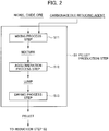
- the method for smelting saprolite ore according to the present embodiment includes a pellet production step S1 of producing a pellet from the saprolite ore, a reduction step S2 of heat-reducing the resulting pellet at a predetermined reduction temperature in a reducing furnace, and a separation step S3 of separating a metal from a slag generated in the reduction step S2 to recover the metal.
- a pellet is produced from saprolite ore serving as raw material ore.
- an example of the composition (weight%) of saprolite ore is shown in the following Table 2. However, the composition of saprolite ore shall not be limited to this.
- [Table 2] Composition of saprolite ore (in terms of metal,wt%) Fe Ni Si Ca Al Mg Co Cr Mn 18.0 1.8 18.0 0.10 0.60 11.0 0.04 1.0 0.29
- Fig. 2 is a process flowchart showing the flow of processing in the pellet production step S1.
- the pellet production step S1 includes a mixing process step S11 of mixing a raw material including the saprolite ore, an agglomeration process step S12 of forming (granulating) the resulting mixture into a lump, and a drying process step S13 of drying the resulting lump.
- a raw material powder containing saprolite ore is mixed to obtain a mixture.
- the carbonaceous reducing agent was added and mixed along with saprolite ore serving as raw material ore, and powders of a flux component, a binder, and the like as optional components are mixed to obtain a mixture, the powders having a particle size, for example, on the order of 0.2 mm to 0.8 mm.
- a specific amount of a carbonaceous reducing agent is mixed to obtain a mixture, which is then used to form the pellet.
- the carbonaceous reducing agent includes coal powder, coke powder and the like. It is noted that the carbonaceous reducing agent preferably has a particle size similar to that of the aforementioned saprolite ore as raw material ore.
- the mixed amount of the carbonaceous reducing agent is adjusted so that the amount of carbon is 25% or less when the total value of a chemical equivalent required for reducing the total amount of nickel oxide contained in the resulting pellet into nickel metal and a chemical equivalent required for reducing iron oxide contained in said pellet into iron metal (which may be referred to as the "total value of the chemical equivalents") is taken as 100%.
- a specific mixed amount of the carbonaceous reducing agent is mixed with the saprolite ore, i.e., the mixed amount of the carbonaceous reducing agent is adjusted so that the amount of carbon is 25% or less relative to the aforementioned total value of the chemical equivalents being 100%. Then, a pellet is produced from the resulting mixture.
- This can effectively reduce trivalent iron oxide into divalent iron oxide, and can also convert nickel oxide into metal, and further can reduce the divalent iron oxide into metal to form a metal shell in the reduction heat treatment in the next reduction step S2 as described in detail below.
- partial reduction treatment can be performed in which some of the iron oxide contained in the shell is allowed to remain as oxide.
- the lower limit of the mixed amount of a carbonaceous reducing agent is preferably adjusted so that the amount of carbon is in a proportion of 0.1% or more relative to the total value of the chemical equivalents being 100% in view of a reaction rate.
- a binder, a flux component, and the like can be added as optional additive components in addition to the carbonaceous reducing agent.
- the binder can include bentonite, polysaccharide, resin, water glass, dewatered cake, and the like.
- the flux component can include calcium oxide, calcium hydroxide, calcium carbonate, silicon dioxide and the like.
- the addition amount of an additive such as a binder and a flux component as described above is preferably 10% or less relative to the mixed amount of the saprolite ore included in the raw material composition.
- an additive such as a binder and a flux component as described above
- the addition amount of such an additive is 10% or less relative to the saprolite ore
- a slag formed by reductively treating a pellet can remain more effectively at a half-molten state. This can prevent an iron-metal forming reaction, further improving the nickel grade.
- the mixture of raw material powders obtained in the mixing process step S11 is formed (granulated) into a lump. Specifically, an amount of water required for agglomeration is added to the mixture obtained in the mixing process step S11, and a pellet-like lump is formed with a lump production device (such as a rolling granulator, a compression molding machine, and an extrusion machine) or by hand.
- a lump production device such as a rolling granulator, a compression molding machine, and an extrusion machine
- the shape of the pellet may be, for example, spherical.
- the size of the lump to be formed into a pellet-like shape but it may be, for example, on the order of 10 mm to 30 mm in terms of the size of a pellet (or the diameter in the case of a spherical pellet) to be charged into a smelting furnace in the reduction step after subjected to the drying process and the preheat treatment described below.
- the lump obtained from the agglomeration process step S12 is subjected to a drying process.
- the lump formed into a pellet-like lump in the agglomeration process has an excess content of water as high as, for example, about 50 wt%, resulting in a sticky condition.
- a drying process is performed so that the solid content of the lump is, for example, about 70 wt%, and the water content is about 30 wt% in order to facilitate the handling of the pellet-like lump.
- drying process of a lump in the drying process step S13 there is no particular limitation for the drying process of a lump in the drying process step S13, but more specifically, hot air, at 300°C to 400°C for example, may be blown against the lump for drying. It is noted that the temperature of a lump when performing the drying process is less than 100°C.
- a raw material powder containing saprolite ore as raw material ore is mixed as described above, and the resulting mixture is granulated (agglomerated) into a pellet-like shape, and dried to produce a pellet.
- a specific amount of a carbonaceous reducing agent is mixed depending on the composition of the saprolite ore as described above when mixing raw material powders, and the resulting mixture is used to produce a pellet.
- the size of the resulting pellet is on the order of 10 mm to 30 mm.
- Pellets are to be produced which are strong enough to maintain the shapes thereof, such that, for example, the proportion of collapsed pellets is about 1% or less even after they are dropped from a height of 1 m.
- Such pellets can withstand impacts of dropping and the like upon charging in the subsequent step of the reduction step S2, and can maintain their pellet-like shapes. Further, appropriate spaces will be formed between pellets. These can allow a smelting reaction in the smelting step to progress appropriately.
- a preheat treatment step may be included in this pellet production step S1, the preheat treatment step including preheating lumped pellets subjected to the drying process in the drying process step S13 described above to a predetermined temperature.
- Production of pellets via preheating a lump after the drying process as described above can reduce cracks (breaking, crumbling) in pellets induced by heat shock more effectively even when pellets are heat-reduced at a temperature as high as, for example, about 1400°C in the reduction step S2.
- the proportion of crumbled pellets relative to the total pellets charged into a smelting furnace can be reduced to a low level, and the pellet-like shape can be maintained more effectively.
- pellets after the drying process are preheated at a temperature of 350°C to 600°C.
- the preheat treatment is preferably performed at a temperature of 400°C to 550°C.
- Preheat treatment performed at a temperature of 350°C to 600°C, preferably at a temperature of 400°C to 550°C as described above can reduce crystal water contained in the saprolite ore in the pellets. Therefore, collapsing of pellets due to the release of their crystal water can be prevented even when the temperature is rapidly increased by being charged into a smelting furnace at about 1400°C.
- the preheat treatment performed as described above allows the thermal expansion of particles of saprolite ore, a carbonaceous reducing agent, a binder, a flux component, and the like that compose the pellets to proceed slowly in two steps. This, in turn, can prevent collapse of the pellets due to differential expansion of particles.
- the processing time for the preheat treatment can be appropriately adjusted depending on the size of a lump containing saprolite ore. It may be, however, on the order of 10 minutes to 60 minutes when a commonly sized lump is used, from which a pellet with a size on the order of 10 mm to 30 mm can be obtained.
- the pellet obtained from the pellet production step S1 is heat-reduced at a predetermined reduction temperature.
- This reduction heat treatment of the pellet in the reduction step S2 promotes a smelting reaction (reduction reaction) to generate metal and slag.
- the reducing heat treatment in the reduction step S2 is performed in a smelting furnace (reducing furnace) and the like.
- a pellet containing saprolite ore is charged into the smelting furnace heated to a predetermined temperature for performing heat reduction.
- the reduction heat treatment of a pellet is preferably performed at 1350°C or more and 1550°C or less.
- a heat reduction temperature of less than 1350°C may not be able to effectively promote a reduction reaction.
- a heat reduction temperature of more than 1550°C may excessively promote a reduction reaction, resulting in a decreased nickel grade.
- the temperature when a pellet is charged into a smelting furnace is preferably 600°C or less. Further, it is more preferably 550°C or less in view that the possibility of burning a pellet due to a carbonaceous reducing agent can be more efficiently reduced.
- the furnace floor of said smelting furnace is pre-covered with a carbonaceous reducing agent (hereinafter referred to as the "furnace floor carbonaceous reducing agent"), and pellets are loaded onto said furnace floor carbonaceous reducing agent pre-covering the floor to perform reduction heat treatment.
- a carbonaceous reducing agent hereinafter referred to as the "furnace floor carbonaceous reducing agent”
- the furnace floor 1a of a smelting furnace 1 is pre-covered with a furnace floor carbonaceous reducing agent 10, for example, coal powder and the like, onto which a produced pellet 20 is loaded to perform the reduction heat treatment.
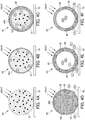
- Figs. 4A to 4F schematically show the course of the reduction reaction in a pellet when the reduction heat treatment is performed in the reduction step S2.
- the furnace floor of the smelting furnace is pre-covered with a furnace floor carbonaceous reducing agent 10, and a pellet 20 is loaded onto that furnace floor carbonaceous reducing agent 10, and then the reduction heat treatment is started.
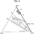
- phase diagram of the FeO-SiO 2 -CaO ternary system is shown in Fig. 5
- a line representing the change in the composition of a slag is shown over the phase diagram.
- the solid line shown in Fig. 5 represents a melting temperature of a slag, showing regions where a slag has a low melting point are present in a region where the proportion of FeO is large (the center to the lower right side of the triangle).
- Almost no Ca is contained in the saprolite ore of raw material ore, and thus, in the present embodiment, the composition of a slag charges along a line representing a composition having almost no Ca and the like in the phase diagram shown in Fig. 5 .
- the mixed amount of a carbonaceous reducing agent in a pellet is adjusted so that the amount of carbon is 25% or less relative to the aforementioned total value of the chemical equivalents being 100%. This can prevent an iron-metal forming reaction based on the aforementioned mechanism.
- Figs. 4D to 4E schematically show how these reactions take place in the inside of the pellet in a more specific way. That is, the reduction reaction progresses from the surface layer portion 20a of the pellet 20 by heating to produce the metal shell 30.
- the amount of the carbonaceous reducing agent 15 in the pellet is adjusted so that the amount of carbon is 25% or less relative to the aforementioned total value of the chemical equivalents being 100%. This reduces the total amount of metals (nickel and iron) produced in the reduction reaction, making the metal shell 30 very thin.
- some iron is progressively converted into metal (FeO -> Fe) at the same time as iron becomes FeO, and melting of the slag 50 progresses ( Fig. 4D ).
- metal particles 40 are produced when some of nickel and iron are converted into iron in the inside of the pellet.
- the rate of forming iron metal increases, the amount of FeO decreases, and the melting temperature of the slag 50 increases, resulting in re-solidification of the slag 50 ( Fig. 4E ) as described above.
- the slag 50 solidified as described above is in a state where the metal particles 40 are dispersed therein. Meanwhile, the metal shell 30 will be melted due to the carburization from the furnace-floor carbonaceous reducing agent 10 arranged to cover the furnace floor 1a. However, the amount of the metal shell 30 is small, and thus the metal shell 30 remains at the surface layer portion 20a in the lower part of the pellet 20 due to surface tension ( Fig. 4F ). Reduction continues to progress due to a CO gas generated from the carbonaceous reducing agent 10 arranged to cover the furnace floor 1a, but the rate of the reduction is slow, because the slag 50 is fixed, resulting in reduced formation of iron metal.
- the amount of the carbonaceous reducing agent 15 to be included in the pellet 20 is adjusted so that the amount of carbon is 25% or less relative to the total value of the chemical equivalents being 100%. This can effectively reduce formation of iron metal.
- the amount of Ca is low in the saprolite ore as raw material ore. Therefore, an excessive addition of, for example, limestone, may produce the composition of a slag represented by the dotted line of the "P line" shown in the phase diagram of Fig. 5 or the composition of a slag having a high level of Ca represented by the "Q line," resulting in conditions where the slag is allowed to melt.
- a liquid phase generated due to the molten slag may increase the reduction kinetics of forming iron metal. If this occurs, the iron-metal forming reaction is difficult to be prevented.
- an additive such as a flux is not added, or the addition amount of the additive is 10% or less relative to the mixed amount of the saprolite ore. This can effectively assure that the slag 50 remains in a half-molten state to reduce the iron-metal forming reaction more effectively.
- the process is preferably performed such that the time from charging the pellet 20 into the smelting furnace 1 to start the heat reduction treatment until taking out the pellet 20 from the smelting furnace is less than 40 minutes. Further, the pellet 20 is preferably cooled to a temperature of 500°C or below within 8 minutes after taken out from the furnace. As described above, the time from the start of the heat reduction treatment until the taking out from the furnace is less than 40 minutes, and cooling is performed such that the temperature becomes 500°C or below within 8 minutes. These can efficiently prevent the reduction reaction of the pellet 20, and stop the reduction of iron oxide present inside the metal shell 30 to prevent a decreased nickel grade.
- the metal shell 30 and the metal particles 40 can be formed by virtue of a specific amount of the carbonaceous reducing agent 15 mixed in the pellet 20.
- nickel oxide is converted into metal while divalent iron oxide obtained from reduction of trivalent iron oxide is only partly reduced into metal. Consequently, the production of iron metal is reduced.
- the heat reduction treatment is performed in a condition where the furnace floor 1a of the smelting furnace 1 is covered with the furnace-floor carbonaceous reducing agent 10.
- the amount of the carbonaceous reducing agent 15 to be mixed in the pellet 20 is adjusted to a specific ratio, i.e., adjusted so that the amount of carbon is 25% or less relative to the aforementioned total value of the chemical equivalents being 100%.
- the carbonaceous reducing agent 15 in that amount is mixed with other raw materials to procure the pellet 20, which is then subjected to the heat reduction treatment. This can allow a so-called partial reduction where some of iron oxide present in the resulting metal shell 30 remains unreduced in the reduction reaction, creating a state where the metal shell 30 which is thin and fragile remains. That is, formation of iron metal can be prevented effectively.
- the metal and the slag separately produced in the pellet 20 will not be mixed together, but form a mixture where the metal solid phase and the slag solid phase coexist as separate phases after subsequent cooling.
- the volume of this mixture is reduced to a volume on the order of 50% to 60% as compared with that of the charged pellet.
- the metal and the slag produced in the reduction step S2 are separated to recover the metal.
- the metal phase is separated and recovered from a mixture containing the metal phase (the metal solid phase) and the slag phase (the slag solid phase containing a carbonaceous reducing agent) in the thin metal shell 30 obtained from the reduction heat treatment of the pellet 20.
- the gravity separation method, the magnetic separation method and the like can used in addition to a method for removing large-sized particulate metal by sieving after cracking or grinding.
- the thin metal shell 30 is first crushed to crush a mixture of the metal and slag phases inside the metal shell, and sieving is performed followed by magnetic separation and the like.
- the resulting metal and slag phases have poor wettability, allowing them to be separated easily.
- the metal and slag phases are separated as described above to recover the metal phase. It is noted the metal recovered in this way may be melted to manufacture a ferronickel (with a nickel grade of 16% or more).
- Saprolite ore serving as raw material ore having a composition shown in Table 2 was mixed with a carbonaceous reducing agent to obtain a mixture.
- the mixed amount of the carbonaceous reducing agent included in the mixture was such that the amount of carbon was 6% relative to the total value of a chemical equivalent required for reducing nickel oxide contained in the resulting pellet into nickel metal and a chemical equivalent required for reducing iron oxide contained in said pellet into iron metal (the total value of the chemical equivalents) being 100%.
- the furnace floor of a smelting furnace was covered with a coal powder (carbon content: 85 wt%, particle size: 0.4 mm) which served as a carbonaceous reducing agent, and 100 produced pellets were then charged so as to be loaded onto the furnace floor carbonaceous reducing agent arranged to cover the furnace floor thereof.
- the pellets were charged into the smelting furnace at a temperature condition of 600°C or less.
- Raw materials were mixed in a similar way as in Example 1 to obtain a mixture, and then pellets were manufactured. At this time, the mixed amount of the carbonaceous reducing agent as a raw material was such that the amount of carbon was 20% relative to the aforementioned total value of the chemical equivalents being 100%.
- the furnace floor of a smelting furnace was covered with a coal powder (carbon content: 85 wt%, particle size: 0.4 mm) which served as a carbonaceous reducing agent, and 100 produced pellets were then charged so as to be loaded onto the furnace floor carbonaceous reducing agent arranged to cover the furnace floor thereof.
- the pellets were charged into the smelting furnace at a temperature condition of 600°C or less.
- Reduced pellets were obtained from the heat reduction treatment performed in this way.
- Metal grades in the reduced pellets were determined in a similar way as in Example 1.
- the nickel and iron grades in the resulting metal are shown in Table 4 below.
- the nickel grade is 16%, which satisfies the nickel grade of 16% in ferronickels required by JIS.
- the recovery rate of nickel is 95% or more as calculated from the mass balance based on the ore composition shown in Table 2.
- Saprolite ore with a composition shown in Table 2 as raw material ore, limestone as a flux, and a binder as well as a carbonaceous reducing agent were mixed to obtain a mixture.
- the raw materials were mixed to obtain a mixture, and then dry pellets were manufactured.
- the mixed amount of the limestone as a flux was 8% in terms of the weight of the limestone relative to the mixed weight of the saprolite ore at this time.
- the mixed amount of the binder was 1% relative to the mixed weight of the saprolite ore.
- the mixed amount of the carbonaceous reducing agent was 6% in terms of the carbon content relative to the aforementioned total value of the chemical equivalents being 100%.
- the furnace floor of a smelting furnace was covered with a coal power (carbon content: 85 wt%, particle size: 0.4 mm) which served as a carbonaceous reducing agent, and 100 produced pellets were then charged so as to be loaded onto the carbonaceous reducing agent arranged to cover the furnace floor thereof.
- the pellets were charged into the smelting furnace under a temperature condition of 600°C or less.
- Nickel and iron grades in the resulting metal are shown in Table 5 below. As shown in Table 5, the nickel grade is 20%, which is significantly higher than the nickel grade of 16% in ferronickels required by JIS. Further, the recovery rate of nickel is 95% or more as calculated from the mass balance based on the ore composition shown in Table 2. [Table 5] Grade [%] Ni Fe Metal 20 78
- Example 4 A mixture was obtained in a similar way as in Example 1, and then pellets were manufactured. The resulting pellets were subjected to the heat reduction treatment in similar conditions. In Example 4, the pellets were taken out from the furnace 30 minutes after the start of the heat reduction treatment, and then assured to be cooled to 500°C or below within 1 minute after taken out from the furnace.
- Nickel and iron grades in the resulting metal are shown in Table 6 below. As shown in Table 6, the nickel grade is 16%, which satisfies the nickel grade of 16% in ferronickel required by JIS. Further, the recovery rate of nickel is 95% or more as calculated from the mass balance based on the ore composition shown in Table 2. [Table 6] Grade [%] Ni Fe Metal 16 82
- the heat reduction treatment was performed in a similar was as in Example 1 except that only the pellets were charged into the smelting furnace without covering the furnace floor of the smelting furnace with a coal powder as the carbonaceous reducing agent.
- Raw materials were mixed in a similar way as in Example 1 to obtain a mixture, and then dry pellets were produced.
- the mixed amount of the carbonaceous reducing agent as a raw material was such that the amount of carbon was 30% relative to the aforementioned total value of the chemical equivalents being 100%.
- the furnace floor of a smelting furnace was covered with a coal powder (carbon content: 85 wt%, particle size: 0.4 mm) which served as a carbonaceous reducing agent, and 100 produced pellets were then charged so as to be loaded onto the furnace floor carbonaceous reducing agent arranged to cover the furnace floor thereof.
- the pellets were charged into the smelting furnace at a temperature condition of 600°C or less.
- Reduced pellets were obtained from the heat reduction treatment performed in this way.
- the resulting reduced pellets were analyzed as in Example 1.
- the nickel and iron grades in the resulting metal are shown in Table 7 below. As shown in Table 7, the nickel grade was 11%, showing that nickel in the metal was not sufficiently enriched, and a metal satisfying the ferronickel grade (a nickel grade of 16% or more) was not able to be obtained. [Table 7] Grade [%] Ni Fe Metal 11 87
- Raw materials were mixed to obtain a mixture in a similar way as in Example 1, and then dry pellets were manufactured. Then 100 pieces of the resulting pellets were charged so as to be loaded on the carbonaceous reducing agent arranged to cover the furnace floor. It is noted that charging the pellets into the smelting furnace was performed at a temperature condition of 600°C or below.
- Raw materials were mixed to obtain a mixture in a similar way as in Example 1, and then dry pellets were manufactured. Then 100 pieces of the resulting pellets were charged so as to be loaded on the carbonaceous reducing agent arranged to cover the furnace floor. It is noted that charging the pellets into the smelting furnace was performed at a temperature condition of 600°C or below.
- Example 3 A mixture was obtained in a similar way as in Example 3, and then pellets were manufactured. The resulting pellets were subjected to the heat reduction treatment in similar conditions.
- Reduced pellets were obtained from the heat reduction treatment performed in this way.
- the resulting reduced pellets were analyzed as in Example 1.
- the metal and iron grades in the resulting reduced pellets are shown in Table 9 below.
- the nickel grade was 14%, showing that nickel in the metal was not sufficiently enriched, and a metal satisfying the ferronickel grade (a nickel grade of 16% or more) was not able to be obtained.
- Grade [%] Ni Fe Metal 14 85
- Raw materials were mixed to obtain a mixture in a similar way as in Example 1, and then dry pellets were manufactured. Then 100 pieces of the resulting pellets were charged so as to be loaded on the carbonaceous reducing agent arranged to cover the furnace floor. It is noted that charging the pellets into the smelting furnace was performed at a temperature condition of 600°C or below.
Landscapes
- Chemical & Material Sciences (AREA)
- Engineering & Computer Science (AREA)
- Organic Chemistry (AREA)
- Materials Engineering (AREA)
- Metallurgy (AREA)
- Manufacturing & Machinery (AREA)
- Mechanical Engineering (AREA)
- Life Sciences & Earth Sciences (AREA)
- Environmental & Geological Engineering (AREA)
- General Life Sciences & Earth Sciences (AREA)
- Geochemistry & Mineralogy (AREA)
- Geology (AREA)
- Manufacture And Refinement Of Metals (AREA)
- Manufacture Of Iron (AREA)
Claims (4)
- Procédé de fusion d'un minerai de saprolite, dans lequel une boulette est formée à partir du minerai de saprolite, et la boulette est soumise à une réduction thermique pour obtenir un alliage de fer-nickel ayant un titre en nickel de 16 % ou plus, le procédé comprenant :une étape de production de boulette comprenant la production d'une boulette à partir du minerai de saprolite, etune étape de réduction comprenant la réduction thermique de la boulette résultante dans un four de fusion,l'étape de production de boulette comprenant le mélange du minerai de saprolite avec au moins un agent carboné de réduction, la quantité mélangée de l'agent carboné de réduction étant ajustée de telle sorte que la quantité de carbone soit de 0,1 % ou plus et 25 % ou moins quand la valeur totale d'un équivalent chimique nécessaire pour réduire un oxyde de nickel contenu dans la boulette résultante en nickel métallique et d'un équivalent chimique nécessaire pour réduire un oxyde de fer contenu dans ladite boulette en fer métallique est prise à 100 %, et l'agglomération du mélange résultant pour former une boulette, etl'étape de réduction comprenantle recouvrement préalable d'une sole de four du four de fusion avec un agent carboné de réduction pour sole de four en une quantité qui permet à une coque métallique formée dans le procédé de l'étape de réduction d'être fondueavant le chargement de la boulette résultante dans le four de fusion,le chargement de la boulette sur l'agent carboné de réduction pour sole de four, etla réduction thermique de la boulette chargée sur l'agent carboné de réduction pour sole de four à une température de chauffage de 1350 °C ou plus et 1550 °C ou moins, dans lequel la durée du début du traitement de réduction thermique jusqu'à ce que la boulette soit retirée du four de fusion dans l'étape de réduction est inférieure à 40 minutes.
- Procédé de fusion d'un minerai de saprolite selon la revendication 1, dans lequel la température quand la boulette est chargée dans le four de fusion est de 600 °C ou moins.
- Procédé de fusion d'un minerai de saprolite selon la revendication 1, dans lequel l'étape de production de boulette comprend l'ajout d'un additif autre que l'agent carboné de réduction de façon que la quantité de chargement de l'additif excepté l'agent carboné de réduction soit de 10 % ou moins par rapport au minerai de saprolite en poids.
- Procédé de fusion d'un minerai de saprolite selon la revendication 1, comprenant en outre la pulvérisation d'un produit réduit obtenu à partir de l'étape de réduction, et la séparation d'un métal incluant l'alliage de fer-nickel à partir d'une scorie, et ensuite la fusion du métal pour obtenir un ferronickel.
Applications Claiming Priority (2)
| Application Number | Priority Date | Filing Date | Title |
|---|---|---|---|
| JP2015033941A JP5958576B1 (ja) | 2015-02-24 | 2015-02-24 | サプロライト鉱の製錬方法 |
| PCT/JP2015/083784 WO2016136068A1 (fr) | 2015-02-24 | 2015-12-01 | Procédé de fusion de minerai de saprolite |
Publications (3)
| Publication Number | Publication Date |
|---|---|
| EP3252178A4 EP3252178A4 (fr) | 2017-12-06 |
| EP3252178A1 EP3252178A1 (fr) | 2017-12-06 |
| EP3252178B1 true EP3252178B1 (fr) | 2019-08-07 |
Family
ID=56550455
Family Applications (1)
| Application Number | Title | Priority Date | Filing Date |
|---|---|---|---|
| EP15883358.2A Active EP3252178B1 (fr) | 2015-02-24 | 2015-12-01 | Procédé de fusion de minerai de saprolite |
Country Status (8)
| Country | Link |
|---|---|
| US (1) | US10301704B2 (fr) |
| EP (1) | EP3252178B1 (fr) |
| JP (1) | JP5958576B1 (fr) |
| CN (1) | CN107208181B (fr) |
| AU (1) | AU2015384741B2 (fr) |
| CA (1) | CA2977450C (fr) |
| PH (1) | PH12017501515A1 (fr) |
| WO (1) | WO2016136068A1 (fr) |
Families Citing this family (9)
| Publication number | Priority date | Publication date | Assignee | Title |
|---|---|---|---|---|
| WO2018073891A1 (fr) * | 2016-10-18 | 2018-04-26 | 日揮株式会社 | Procédé de production de ferronickel |
| JP6907705B2 (ja) * | 2017-05-24 | 2021-07-21 | 住友金属鉱山株式会社 | 酸化鉱石の製錬方法 |
| JP6439828B2 (ja) * | 2017-05-24 | 2018-12-19 | 住友金属鉱山株式会社 | 酸化鉱石の製錬方法 |
| JP6926674B2 (ja) * | 2017-05-24 | 2021-08-25 | 住友金属鉱山株式会社 | 酸化鉱石の製錬方法 |
| JP7321776B2 (ja) * | 2019-05-28 | 2023-08-07 | 株式会社日向製錬所 | フェロニッケル鋳造片の黒色化抑制方法、及び、フェロニッケル鋳造片の製造方法 |
| JP7439540B2 (ja) * | 2020-01-30 | 2024-02-28 | 住友金属鉱山株式会社 | 酸化鉱石の製錬方法 |
| JP2023019428A (ja) * | 2021-07-29 | 2023-02-09 | 住友金属鉱山株式会社 | ニッケル酸化鉱石の製錬方法 |
| JP2023111361A (ja) * | 2022-01-31 | 2023-08-10 | 住友金属鉱山株式会社 | ニッケル酸化鉱石の製錬方法 |
| EP4560034A4 (fr) * | 2022-07-21 | 2025-12-24 | Sumitomo Metal Mining Co | Procédé de fusion de minerai d'oxyde contenant du nickel |
Family Cites Families (32)
| Publication number | Priority date | Publication date | Assignee | Title |
|---|---|---|---|---|
| GB929201A (en) * | 1959-08-24 | 1963-06-19 | Tohoku Denki Seitetsu Kabushik | Method of recovering nickel and iron from laterite ore by preferential reduction |
| GB1261127A (en) * | 1968-10-15 | 1972-01-19 | Conzinc Riotinto Ltd | Shaft furnace smelting of oxidic ores, concentrates or calcines |
| CA958221A (en) | 1970-07-10 | 1974-11-26 | Fritz O. Wienert | Production of metallurgical pellets in rotary kilns |
| US3849113A (en) * | 1973-06-12 | 1974-11-19 | Mcdowell Wellman Eng Co | Process for the production of crude ferronickel |
| US3854936A (en) * | 1973-09-26 | 1974-12-17 | Us Interior | Smelting of nickel oxide ores to produce ferronickel |
| CA1011955A (en) * | 1973-11-05 | 1977-06-14 | Inco Limited | Process for treatment of lateritic ores |
| US4195986A (en) * | 1978-10-06 | 1980-04-01 | Allis-Chalmers Corporation | Selective reduction of nickel laterite ores |
| US4490169A (en) * | 1980-07-21 | 1984-12-25 | Lectromelt Corporation | Method for reducing ore |
| US4445932A (en) * | 1982-07-12 | 1984-05-01 | Gosudarstvenny Proektny I Nauchno-Issledovatelsky Institut Gipronikel | Method of recovering ferronickel from oxidated nickel ores |
| JPS6223944A (ja) | 1985-07-22 | 1987-01-31 | Nippon Yakin Kogyo Co Ltd | 酸化ニッケル鉱石からフェロニッケルルッペを製造する方法 |
| US4701217A (en) * | 1986-11-06 | 1987-10-20 | University Of Birmingham | Smelting reduction |
| JPH0448365Y2 (fr) | 1987-07-31 | 1992-11-13 | ||
| US5178666A (en) * | 1991-12-03 | 1993-01-12 | Inco Limited | Low temperature thermal upgrading of lateritic ores |
| JPH05311265A (ja) | 1992-05-06 | 1993-11-22 | Nippon Yakin Kogyo Co Ltd | 高Ni含有フェロニッケルの製造方法 |
| JP2001181720A (ja) | 1999-12-28 | 2001-07-03 | Kobe Steel Ltd | 回転炉床炉による還元鉄製造方法 |
| JP4757982B2 (ja) | 2000-06-28 | 2011-08-24 | 株式会社神戸製鋼所 | 粒状金属鉄の歩留まり向上方法 |
| JP2002285213A (ja) | 2001-03-23 | 2002-10-03 | Kawasaki Steel Corp | 金属含有物からの還元金属の製造方法 |
| JP4120230B2 (ja) | 2002-02-18 | 2008-07-16 | Jfeスチール株式会社 | 移動型炉床炉の操業方法 |
| US20050211020A1 (en) | 2002-10-18 | 2005-09-29 | Hiroshi Sugitatsu | Ferronickel and process for producing raw material for ferronickel smelting |
| JP4348152B2 (ja) * | 2002-10-18 | 2009-10-21 | 株式会社神戸製鋼所 | フェロニッケルおよびフェロニッケル精錬原料の製造方法 |
| CN100497670C (zh) | 2006-12-22 | 2009-06-10 | 昆明贵金属研究所 | 一种转底炉快速还原含碳红土镍矿球团富集镍的方法 |
| CN101392330A (zh) | 2007-09-21 | 2009-03-25 | 毛耐文 | 红土镍矿在隧道窑——高炉中联合生产镍铁的方法 |
| EP2226403B1 (fr) | 2008-09-18 | 2012-06-27 | Sumitomo Metal Mining Co., Ltd. | Procédé de concentration du nickel dans un minerai de saprolite |
| CN101481753B (zh) * | 2008-12-05 | 2010-08-11 | 首钢总公司 | 一种从红土氧化镍矿冶炼镍铁合金的方法 |
| JP2010229525A (ja) * | 2009-03-27 | 2010-10-14 | Kobe Steel Ltd | フェロニッケルおよびフェロバナジウムの製造方法 |
| JP5503420B2 (ja) | 2010-06-07 | 2014-05-28 | 株式会社神戸製鋼所 | 粒状金属の製造方法 |
| CN102643976B (zh) | 2011-02-21 | 2013-10-30 | 宝山钢铁股份有限公司 | 用于红土镍矿生产镍铁颗粒的复合添加剂及其使用方法 |
| JP2014084526A (ja) | 2012-10-26 | 2014-05-12 | Kobe Steel Ltd | 還元鉄の製造方法 |
| JP6014009B2 (ja) | 2012-11-22 | 2016-10-25 | 株式会社神戸製鋼所 | 還元鉄の製造方法 |
| TW201505014A (zh) * | 2013-07-25 | 2015-02-01 | Univ Nat Taiwan | 背光調整影像的強化方法及系統 |
| JP5839090B1 (ja) * | 2014-07-25 | 2016-01-06 | 住友金属鉱山株式会社 | ニッケル酸化鉱の製錬方法、ペレットの装入方法 |
| JP5975093B2 (ja) * | 2014-12-24 | 2016-08-23 | 住友金属鉱山株式会社 | ニッケル酸化鉱の製錬方法 |
-
2015
- 2015-02-24 JP JP2015033941A patent/JP5958576B1/ja active Active
- 2015-12-01 US US15/552,031 patent/US10301704B2/en active Active
- 2015-12-01 EP EP15883358.2A patent/EP3252178B1/fr active Active
- 2015-12-01 WO PCT/JP2015/083784 patent/WO2016136068A1/fr not_active Ceased
- 2015-12-01 CA CA2977450A patent/CA2977450C/fr active Active
- 2015-12-01 AU AU2015384741A patent/AU2015384741B2/en active Active
- 2015-12-01 CN CN201580075742.3A patent/CN107208181B/zh active Active
-
2017
- 2017-08-22 PH PH12017501515A patent/PH12017501515A1/en unknown
Non-Patent Citations (1)
| Title |
|---|
| None * |
Also Published As
| Publication number | Publication date |
|---|---|
| JP2016156043A (ja) | 2016-09-01 |
| CA2977450A1 (fr) | 2016-09-01 |
| US10301704B2 (en) | 2019-05-28 |
| AU2015384741B2 (en) | 2018-10-04 |
| CN107208181B (zh) | 2018-09-25 |
| CA2977450C (fr) | 2017-12-19 |
| PH12017501515B1 (en) | 2018-02-05 |
| US20180030574A1 (en) | 2018-02-01 |
| JP5958576B1 (ja) | 2016-08-02 |
| CN107208181A (zh) | 2017-09-26 |
| WO2016136068A1 (fr) | 2016-09-01 |
| AU2015384741A1 (en) | 2017-09-07 |
| PH12017501515A1 (en) | 2018-02-05 |
| EP3252178A4 (fr) | 2017-12-06 |
| EP3252178A1 (fr) | 2017-12-06 |
Similar Documents
| Publication | Publication Date | Title |
|---|---|---|
| EP3252178B1 (fr) | Procédé de fusion de minerai de saprolite | |
| EP3222737B1 (fr) | Procédé de fusion de minerai d'oxyde de nickel | |
| EP3205732B1 (fr) | Procédé de fusion de minerai d'oxyde de nickel | |
| JP6477371B2 (ja) | ニッケル酸化鉱の製錬方法 | |
| JP5842967B1 (ja) | ペレットの製造方法、鉄−ニッケル合金の製造方法 | |
| JP6179478B2 (ja) | ペレットの製造方法、鉄−ニッケル合金の製造方法 | |
| JP6447429B2 (ja) | ニッケル酸化鉱の製錬方法 | |
| JP5839090B1 (ja) | ニッケル酸化鉱の製錬方法、ペレットの装入方法 | |
| JP6455374B2 (ja) | ニッケル酸化鉱の製錬方法 | |
| JP2024082533A (ja) | ニッケル酸化鉱石の製錬方法 |
Legal Events
| Date | Code | Title | Description |
|---|---|---|---|
| STAA | Information on the status of an ep patent application or granted ep patent |
Free format text: STATUS: THE INTERNATIONAL PUBLICATION HAS BEEN MADE |
|
| PUAI | Public reference made under article 153(3) epc to a published international application that has entered the european phase |
Free format text: ORIGINAL CODE: 0009012 |
|
| STAA | Information on the status of an ep patent application or granted ep patent |
Free format text: STATUS: REQUEST FOR EXAMINATION WAS MADE |
|
| 17P | Request for examination filed |
Effective date: 20170831 |
|
| A4 | Supplementary search report drawn up and despatched |
Effective date: 20171010 |
|
| AK | Designated contracting states |
Kind code of ref document: A1 Designated state(s): AL AT BE BG CH CY CZ DE DK EE ES FI FR GB GR HR HU IE IS IT LI LT LU LV MC MK MT NL NO PL PT RO RS SE SI SK SM TR |
|
| AX | Request for extension of the european patent |
Extension state: BA ME |
|
| DAV | Request for validation of the european patent (deleted) | ||
| DAX | Request for extension of the european patent (deleted) | ||
| STAA | Information on the status of an ep patent application or granted ep patent |
Free format text: STATUS: EXAMINATION IS IN PROGRESS |
|
| 17Q | First examination report despatched |
Effective date: 20180731 |
|
| GRAP | Despatch of communication of intention to grant a patent |
Free format text: ORIGINAL CODE: EPIDOSNIGR1 |
|
| STAA | Information on the status of an ep patent application or granted ep patent |
Free format text: STATUS: GRANT OF PATENT IS INTENDED |
|
| INTG | Intention to grant announced |
Effective date: 20190213 |
|
| RIN1 | Information on inventor provided before grant (corrected) |
Inventor name: INOUE, TAKU Inventor name: TAKAHASHI, JUNICHI Inventor name: OKADA, SHUUJI |
|
| GRAS | Grant fee paid |
Free format text: ORIGINAL CODE: EPIDOSNIGR3 |
|
| GRAA | (expected) grant |
Free format text: ORIGINAL CODE: 0009210 |
|
| STAA | Information on the status of an ep patent application or granted ep patent |
Free format text: STATUS: THE PATENT HAS BEEN GRANTED |
|
| AK | Designated contracting states |
Kind code of ref document: B1 Designated state(s): AL AT BE BG CH CY CZ DE DK EE ES FI FR GB GR HR HU IE IS IT LI LT LU LV MC MK MT NL NO PL PT RO RS SE SI SK SM TR |
|
| REG | Reference to a national code |
Ref country code: GB Ref legal event code: FG4D |
|
| REG | Reference to a national code |
Ref country code: CH Ref legal event code: EP Ref country code: AT Ref legal event code: REF Ref document number: 1163967 Country of ref document: AT Kind code of ref document: T Effective date: 20190815 |
|
| REG | Reference to a national code |
Ref country code: DE Ref legal event code: R096 Ref document number: 602015035619 Country of ref document: DE |
|
| REG | Reference to a national code |
Ref country code: IE Ref legal event code: FG4D |
|
| REG | Reference to a national code |
Ref country code: NL Ref legal event code: MP Effective date: 20190807 |
|
| REG | Reference to a national code |
Ref country code: LT Ref legal event code: MG4D |
|
| PG25 | Lapsed in a contracting state [announced via postgrant information from national office to epo] |
Ref country code: PT Free format text: LAPSE BECAUSE OF FAILURE TO SUBMIT A TRANSLATION OF THE DESCRIPTION OR TO PAY THE FEE WITHIN THE PRESCRIBED TIME-LIMIT Effective date: 20191209 Ref country code: FI Free format text: LAPSE BECAUSE OF FAILURE TO SUBMIT A TRANSLATION OF THE DESCRIPTION OR TO PAY THE FEE WITHIN THE PRESCRIBED TIME-LIMIT Effective date: 20190807 Ref country code: SE Free format text: LAPSE BECAUSE OF FAILURE TO SUBMIT A TRANSLATION OF THE DESCRIPTION OR TO PAY THE FEE WITHIN THE PRESCRIBED TIME-LIMIT Effective date: 20190807 Ref country code: HR Free format text: LAPSE BECAUSE OF FAILURE TO SUBMIT A TRANSLATION OF THE DESCRIPTION OR TO PAY THE FEE WITHIN THE PRESCRIBED TIME-LIMIT Effective date: 20190807 Ref country code: LT Free format text: LAPSE BECAUSE OF FAILURE TO SUBMIT A TRANSLATION OF THE DESCRIPTION OR TO PAY THE FEE WITHIN THE PRESCRIBED TIME-LIMIT Effective date: 20190807 Ref country code: NO Free format text: LAPSE BECAUSE OF FAILURE TO SUBMIT A TRANSLATION OF THE DESCRIPTION OR TO PAY THE FEE WITHIN THE PRESCRIBED TIME-LIMIT Effective date: 20191107 Ref country code: NL Free format text: LAPSE BECAUSE OF FAILURE TO SUBMIT A TRANSLATION OF THE DESCRIPTION OR TO PAY THE FEE WITHIN THE PRESCRIBED TIME-LIMIT Effective date: 20190807 Ref country code: BG Free format text: LAPSE BECAUSE OF FAILURE TO SUBMIT A TRANSLATION OF THE DESCRIPTION OR TO PAY THE FEE WITHIN THE PRESCRIBED TIME-LIMIT Effective date: 20191107 |
|
| REG | Reference to a national code |
Ref country code: AT Ref legal event code: MK05 Ref document number: 1163967 Country of ref document: AT Kind code of ref document: T Effective date: 20190807 |
|
| PG25 | Lapsed in a contracting state [announced via postgrant information from national office to epo] |
Ref country code: ES Free format text: LAPSE BECAUSE OF FAILURE TO SUBMIT A TRANSLATION OF THE DESCRIPTION OR TO PAY THE FEE WITHIN THE PRESCRIBED TIME-LIMIT Effective date: 20190807 Ref country code: AL Free format text: LAPSE BECAUSE OF FAILURE TO SUBMIT A TRANSLATION OF THE DESCRIPTION OR TO PAY THE FEE WITHIN THE PRESCRIBED TIME-LIMIT Effective date: 20190807 Ref country code: LV Free format text: LAPSE BECAUSE OF FAILURE TO SUBMIT A TRANSLATION OF THE DESCRIPTION OR TO PAY THE FEE WITHIN THE PRESCRIBED TIME-LIMIT Effective date: 20190807 Ref country code: RS Free format text: LAPSE BECAUSE OF FAILURE TO SUBMIT A TRANSLATION OF THE DESCRIPTION OR TO PAY THE FEE WITHIN THE PRESCRIBED TIME-LIMIT Effective date: 20190807 Ref country code: IS Free format text: LAPSE BECAUSE OF FAILURE TO SUBMIT A TRANSLATION OF THE DESCRIPTION OR TO PAY THE FEE WITHIN THE PRESCRIBED TIME-LIMIT Effective date: 20191207 Ref country code: GR Free format text: LAPSE BECAUSE OF FAILURE TO SUBMIT A TRANSLATION OF THE DESCRIPTION OR TO PAY THE FEE WITHIN THE PRESCRIBED TIME-LIMIT Effective date: 20191108 |
|
| PG25 | Lapsed in a contracting state [announced via postgrant information from national office to epo] |
Ref country code: TR Free format text: LAPSE BECAUSE OF FAILURE TO SUBMIT A TRANSLATION OF THE DESCRIPTION OR TO PAY THE FEE WITHIN THE PRESCRIBED TIME-LIMIT Effective date: 20190807 |
|
| PG25 | Lapsed in a contracting state [announced via postgrant information from national office to epo] |
Ref country code: RO Free format text: LAPSE BECAUSE OF FAILURE TO SUBMIT A TRANSLATION OF THE DESCRIPTION OR TO PAY THE FEE WITHIN THE PRESCRIBED TIME-LIMIT Effective date: 20190807 Ref country code: IT Free format text: LAPSE BECAUSE OF FAILURE TO SUBMIT A TRANSLATION OF THE DESCRIPTION OR TO PAY THE FEE WITHIN THE PRESCRIBED TIME-LIMIT Effective date: 20190807 Ref country code: PL Free format text: LAPSE BECAUSE OF FAILURE TO SUBMIT A TRANSLATION OF THE DESCRIPTION OR TO PAY THE FEE WITHIN THE PRESCRIBED TIME-LIMIT Effective date: 20190807 Ref country code: AT Free format text: LAPSE BECAUSE OF FAILURE TO SUBMIT A TRANSLATION OF THE DESCRIPTION OR TO PAY THE FEE WITHIN THE PRESCRIBED TIME-LIMIT Effective date: 20190807 Ref country code: EE Free format text: LAPSE BECAUSE OF FAILURE TO SUBMIT A TRANSLATION OF THE DESCRIPTION OR TO PAY THE FEE WITHIN THE PRESCRIBED TIME-LIMIT Effective date: 20190807 Ref country code: DK Free format text: LAPSE BECAUSE OF FAILURE TO SUBMIT A TRANSLATION OF THE DESCRIPTION OR TO PAY THE FEE WITHIN THE PRESCRIBED TIME-LIMIT Effective date: 20190807 |
|
| PG25 | Lapsed in a contracting state [announced via postgrant information from national office to epo] |
Ref country code: CZ Free format text: LAPSE BECAUSE OF FAILURE TO SUBMIT A TRANSLATION OF THE DESCRIPTION OR TO PAY THE FEE WITHIN THE PRESCRIBED TIME-LIMIT Effective date: 20190807 Ref country code: IS Free format text: LAPSE BECAUSE OF FAILURE TO SUBMIT A TRANSLATION OF THE DESCRIPTION OR TO PAY THE FEE WITHIN THE PRESCRIBED TIME-LIMIT Effective date: 20200224 Ref country code: SM Free format text: LAPSE BECAUSE OF FAILURE TO SUBMIT A TRANSLATION OF THE DESCRIPTION OR TO PAY THE FEE WITHIN THE PRESCRIBED TIME-LIMIT Effective date: 20190807 Ref country code: SK Free format text: LAPSE BECAUSE OF FAILURE TO SUBMIT A TRANSLATION OF THE DESCRIPTION OR TO PAY THE FEE WITHIN THE PRESCRIBED TIME-LIMIT Effective date: 20190807 |
|
| REG | Reference to a national code |
Ref country code: DE Ref legal event code: R097 Ref document number: 602015035619 Country of ref document: DE |
|
| REG | Reference to a national code |
Ref country code: DE Ref legal event code: R119 Ref document number: 602015035619 Country of ref document: DE |
|
| PLBE | No opposition filed within time limit |
Free format text: ORIGINAL CODE: 0009261 |
|
| STAA | Information on the status of an ep patent application or granted ep patent |
Free format text: STATUS: NO OPPOSITION FILED WITHIN TIME LIMIT |
|
| PG2D | Information on lapse in contracting state deleted |
Ref country code: IS |
|
| REG | Reference to a national code |
Ref country code: CH Ref legal event code: PL |
|
| 26N | No opposition filed |
Effective date: 20200603 |
|
| REG | Reference to a national code |
Ref country code: BE Ref legal event code: MM Effective date: 20191231 |
|
| PG25 | Lapsed in a contracting state [announced via postgrant information from national office to epo] |
Ref country code: MC Free format text: LAPSE BECAUSE OF FAILURE TO SUBMIT A TRANSLATION OF THE DESCRIPTION OR TO PAY THE FEE WITHIN THE PRESCRIBED TIME-LIMIT Effective date: 20190807 Ref country code: SI Free format text: LAPSE BECAUSE OF FAILURE TO SUBMIT A TRANSLATION OF THE DESCRIPTION OR TO PAY THE FEE WITHIN THE PRESCRIBED TIME-LIMIT Effective date: 20190807 |
|
| PG25 | Lapsed in a contracting state [announced via postgrant information from national office to epo] |
Ref country code: LU Free format text: LAPSE BECAUSE OF NON-PAYMENT OF DUE FEES Effective date: 20191201 Ref country code: IE Free format text: LAPSE BECAUSE OF NON-PAYMENT OF DUE FEES Effective date: 20191201 Ref country code: DE Free format text: LAPSE BECAUSE OF NON-PAYMENT OF DUE FEES Effective date: 20200701 |
|
| PG25 | Lapsed in a contracting state [announced via postgrant information from national office to epo] |
Ref country code: LI Free format text: LAPSE BECAUSE OF NON-PAYMENT OF DUE FEES Effective date: 20191231 Ref country code: BE Free format text: LAPSE BECAUSE OF NON-PAYMENT OF DUE FEES Effective date: 20191231 Ref country code: CH Free format text: LAPSE BECAUSE OF NON-PAYMENT OF DUE FEES Effective date: 20191231 |
|
| PG25 | Lapsed in a contracting state [announced via postgrant information from national office to epo] |
Ref country code: CY Free format text: LAPSE BECAUSE OF FAILURE TO SUBMIT A TRANSLATION OF THE DESCRIPTION OR TO PAY THE FEE WITHIN THE PRESCRIBED TIME-LIMIT Effective date: 20190807 |
|
| PG25 | Lapsed in a contracting state [announced via postgrant information from national office to epo] |
Ref country code: HU Free format text: LAPSE BECAUSE OF FAILURE TO SUBMIT A TRANSLATION OF THE DESCRIPTION OR TO PAY THE FEE WITHIN THE PRESCRIBED TIME-LIMIT; INVALID AB INITIO Effective date: 20151201 Ref country code: MT Free format text: LAPSE BECAUSE OF FAILURE TO SUBMIT A TRANSLATION OF THE DESCRIPTION OR TO PAY THE FEE WITHIN THE PRESCRIBED TIME-LIMIT Effective date: 20190807 |
|
| PG25 | Lapsed in a contracting state [announced via postgrant information from national office to epo] |
Ref country code: MK Free format text: LAPSE BECAUSE OF FAILURE TO SUBMIT A TRANSLATION OF THE DESCRIPTION OR TO PAY THE FEE WITHIN THE PRESCRIBED TIME-LIMIT Effective date: 20190807 |
|
| P01 | Opt-out of the competence of the unified patent court (upc) registered |
Effective date: 20230512 |
|
| PGFP | Annual fee paid to national office [announced via postgrant information from national office to epo] |
Ref country code: FR Payment date: 20250930 Year of fee payment: 11 |
|
| PGFP | Annual fee paid to national office [announced via postgrant information from national office to epo] |
Ref country code: GB Payment date: 20251001 Year of fee payment: 11 |