EP3252256B1 - Ensemble d'appui de fenêtre - Google Patents
Ensemble d'appui de fenêtre Download PDFInfo
- Publication number
- EP3252256B1 EP3252256B1 EP17173408.0A EP17173408A EP3252256B1 EP 3252256 B1 EP3252256 B1 EP 3252256B1 EP 17173408 A EP17173408 A EP 17173408A EP 3252256 B1 EP3252256 B1 EP 3252256B1
- Authority
- EP
- European Patent Office
- Prior art keywords
- bracket
- window
- sacrificial anode
- metal
- bracket assembly
- Prior art date
- Legal status (The legal status is an assumption and is not a legal conclusion. Google has not performed a legal analysis and makes no representation as to the accuracy of the status listed.)
- Active
Links
Images

Classifications
-
- E—FIXED CONSTRUCTIONS
- E05—LOCKS; KEYS; WINDOW OR DOOR FITTINGS; SAFES
- E05D—HINGES OR SUSPENSION DEVICES FOR DOORS, WINDOWS OR WINGS
- E05D9/00—Flaps or sleeves specially designed for making from particular material, e.g. hoop-iron, sheet metal, plastics
-
- C—CHEMISTRY; METALLURGY
- C23—COATING METALLIC MATERIAL; COATING MATERIAL WITH METALLIC MATERIAL; CHEMICAL SURFACE TREATMENT; DIFFUSION TREATMENT OF METALLIC MATERIAL; COATING BY VACUUM EVAPORATION, BY SPUTTERING, BY ION IMPLANTATION OR BY CHEMICAL VAPOUR DEPOSITION, IN GENERAL; INHIBITING CORROSION OF METALLIC MATERIAL OR INCRUSTATION IN GENERAL
- C23F—NON-MECHANICAL REMOVAL OF METALLIC MATERIAL FROM SURFACE; INHIBITING CORROSION OF METALLIC MATERIAL OR INCRUSTATION IN GENERAL; MULTI-STEP PROCESSES FOR SURFACE TREATMENT OF METALLIC MATERIAL INVOLVING AT LEAST ONE PROCESS PROVIDED FOR IN CLASS C23 AND AT LEAST ONE PROCESS COVERED BY SUBCLASS C21D OR C22F OR CLASS C25
- C23F13/00—Inhibiting corrosion of metals by anodic or cathodic protection
- C23F13/02—Inhibiting corrosion of metals by anodic or cathodic protection cathodic; Selection of conditions, parameters or procedures for cathodic protection, e.g. of electrical conditions
- C23F13/06—Constructional parts, or assemblies of cathodic-protection apparatus
- C23F13/08—Electrodes specially adapted for inhibiting corrosion by cathodic protection; Manufacture thereof; Conducting electric current thereto
- C23F13/10—Electrodes characterised by the structure
-
- C—CHEMISTRY; METALLURGY
- C23—COATING METALLIC MATERIAL; COATING MATERIAL WITH METALLIC MATERIAL; CHEMICAL SURFACE TREATMENT; DIFFUSION TREATMENT OF METALLIC MATERIAL; COATING BY VACUUM EVAPORATION, BY SPUTTERING, BY ION IMPLANTATION OR BY CHEMICAL VAPOUR DEPOSITION, IN GENERAL; INHIBITING CORROSION OF METALLIC MATERIAL OR INCRUSTATION IN GENERAL
- C23F—NON-MECHANICAL REMOVAL OF METALLIC MATERIAL FROM SURFACE; INHIBITING CORROSION OF METALLIC MATERIAL OR INCRUSTATION IN GENERAL; MULTI-STEP PROCESSES FOR SURFACE TREATMENT OF METALLIC MATERIAL INVOLVING AT LEAST ONE PROCESS PROVIDED FOR IN CLASS C23 AND AT LEAST ONE PROCESS COVERED BY SUBCLASS C21D OR C22F OR CLASS C25
- C23F13/00—Inhibiting corrosion of metals by anodic or cathodic protection
- C23F13/02—Inhibiting corrosion of metals by anodic or cathodic protection cathodic; Selection of conditions, parameters or procedures for cathodic protection, e.g. of electrical conditions
- C23F13/06—Constructional parts, or assemblies of cathodic-protection apparatus
- C23F13/08—Electrodes specially adapted for inhibiting corrosion by cathodic protection; Manufacture thereof; Conducting electric current thereto
- C23F13/18—Means for supporting electrodes
-
- C—CHEMISTRY; METALLURGY
- C23—COATING METALLIC MATERIAL; COATING MATERIAL WITH METALLIC MATERIAL; CHEMICAL SURFACE TREATMENT; DIFFUSION TREATMENT OF METALLIC MATERIAL; COATING BY VACUUM EVAPORATION, BY SPUTTERING, BY ION IMPLANTATION OR BY CHEMICAL VAPOUR DEPOSITION, IN GENERAL; INHIBITING CORROSION OF METALLIC MATERIAL OR INCRUSTATION IN GENERAL
- C23F—NON-MECHANICAL REMOVAL OF METALLIC MATERIAL FROM SURFACE; INHIBITING CORROSION OF METALLIC MATERIAL OR INCRUSTATION IN GENERAL; MULTI-STEP PROCESSES FOR SURFACE TREATMENT OF METALLIC MATERIAL INVOLVING AT LEAST ONE PROCESS PROVIDED FOR IN CLASS C23 AND AT LEAST ONE PROCESS COVERED BY SUBCLASS C21D OR C22F OR CLASS C25
- C23F13/00—Inhibiting corrosion of metals by anodic or cathodic protection
- C23F13/02—Inhibiting corrosion of metals by anodic or cathodic protection cathodic; Selection of conditions, parameters or procedures for cathodic protection, e.g. of electrical conditions
- C23F13/06—Constructional parts, or assemblies of cathodic-protection apparatus
- C23F13/08—Electrodes specially adapted for inhibiting corrosion by cathodic protection; Manufacture thereof; Conducting electric current thereto
- C23F13/20—Conducting electric current to electrodes
-
- E—FIXED CONSTRUCTIONS
- E04—BUILDING
- E04D—ROOF COVERINGS; SKY-LIGHTS; GUTTERS; ROOF-WORKING TOOLS
- E04D13/00—Special arrangements or devices in connection with roof coverings; Protection against birds; Roof drainage ; Sky-lights
- E04D13/03—Sky-lights; Domes; Ventilating sky-lights
- E04D13/0305—Supports or connecting means for sky-lights of flat or domed shape
- E04D13/031—Supports or connecting means for sky-lights of flat or domed shape characterised by a frame for connection to an inclined roof
-
- E—FIXED CONSTRUCTIONS
- E05—LOCKS; KEYS; WINDOW OR DOOR FITTINGS; SAFES
- E05D—HINGES OR SUSPENSION DEVICES FOR DOORS, WINDOWS OR WINGS
- E05D7/00—Hinges or pivots of special construction
- E05D7/08—Hinges or pivots of special construction for use in suspensions comprising two spigots placed at opposite edges of the wing, especially at the top and the bottom, e.g. trunnions
- E05D7/081—Hinges or pivots of special construction for use in suspensions comprising two spigots placed at opposite edges of the wing, especially at the top and the bottom, e.g. trunnions the pivot axis of the wing being situated near one edge of the wing, especially at the top and bottom, e.g. trunnions
-
- E—FIXED CONSTRUCTIONS
- E05—LOCKS; KEYS; WINDOW OR DOOR FITTINGS; SAFES
- E05Y—INDEXING SCHEME ASSOCIATED WITH SUBCLASSES E05D AND E05F, RELATING TO CONSTRUCTION ELEMENTS, ELECTRIC CONTROL, POWER SUPPLY, POWER SIGNAL OR TRANSMISSION, USER INTERFACES, MOUNTING OR COUPLING, DETAILS, ACCESSORIES, AUXILIARY OPERATIONS NOT OTHERWISE PROVIDED FOR, APPLICATION THEREOF
- E05Y2800/00—Details, accessories and auxiliary operations not otherwise provided for
- E05Y2800/40—Physical or chemical protection
- E05Y2800/402—Physical or chemical protection against corrosion
-
- E—FIXED CONSTRUCTIONS
- E05—LOCKS; KEYS; WINDOW OR DOOR FITTINGS; SAFES
- E05Y—INDEXING SCHEME ASSOCIATED WITH SUBCLASSES E05D AND E05F, RELATING TO CONSTRUCTION ELEMENTS, ELECTRIC CONTROL, POWER SUPPLY, POWER SIGNAL OR TRANSMISSION, USER INTERFACES, MOUNTING OR COUPLING, DETAILS, ACCESSORIES, AUXILIARY OPERATIONS NOT OTHERWISE PROVIDED FOR, APPLICATION THEREOF
- E05Y2900/00—Application of doors, windows, wings or fittings thereof
- E05Y2900/10—Application of doors, windows, wings or fittings thereof for buildings or parts thereof
- E05Y2900/13—Type of wing
- E05Y2900/148—Windows
- E05Y2900/152—Roof windows
- E05Y2900/154—Skylights
Definitions
- the present invention relates to a window bracket assembly for use in connection with a window, comprising a metal bracket and at least one sacrificial anode, use of a window mounting assembly and a window provided with said bracket assembly.
- Corrosion is a chemical process where for example oxygen reacts with a metal such as iron and form iron oxide, a.k.a. rust, particularly in the presence of an electrolyte, such as aqueous saline solutions.
- anode In the process electrons are removed from the metal, which then is referred to as the anode, and transferred to a different area, which doesn't corrode and which is referred to as the cathode.
- brackets When it comes to windows and doors, the brackets are traditionally made of steel, but when they are to be used in strongly corrosive environments such as for indoor swimming pools categorized as C4 in the ISO 1461 corrosion category, steel will corrode too quickly in relation to expected lifetime of the window. This is because of the high humidity content and the high content of chlorine/chlorine amines or hydrochloric acid compounds in the air. Small perforations in the vapor barrier may result in chlorine containing vapour building up and condensing on the brackets. Since the brackets are often placed on large windows and may be hidden in the construction, they are hard to replace and other kinds of corrosive treatments need to be applied.
- Examples of corrosion protection with sacrificial anodes in buildings can be found in JPS61237788, upon which the peample of claim 1 is based, and JP2014214314 .
- alternative protection are required, but the known methods all have their drawbacks.
- coatings of different kinds such as aqua and epoxy coating, powder coating, have proven not to be sufficiently scratch resistant and the protective layer may therefore be broken during installation or corrosion will creep under the protective layer.
- galvanization or chromate conversion coating is another example; however, the layer required to protect the bracket, and the screws for that matter, would be too thick to make it feasible to manufacture, when it has to resist corrosion for an extended time in a strongly corrosive environment.
- this is achieved with a window bracket assembly according to claim 1.
- the metal bracket may be used to mounting a roof window, a façade window or any other kind of window.
- a bracket is to be understood as any kind of bracket or furniture used on a window or a door for that matter, such as mounting brackets, fasteners, hooks, stays, hinges, closure elements, bearings etc.
- the window may be fixed or it may be able to open.
- an electrolyte is required.
- the electrolyte may be present because a water vapor barrier is perforated and precipitation seeps into the construction, or the ceiling or wall has not been insulated correctly.
- the electrolyte may also come from inside the building in the form of water vapor generated in a heated room such as a swimming bath.
- a bracket which directly, or indirectly through a cold bridge, is in contact with the cooler outside air
- the vapor will condense.
- the condensed vapor is as such free from salts but will try to react with conductive substanses in the air such as chlorine compounds thereby forming a conductive fluid.
- a strongly corrosive environment will form, but also an environment suitable for use of a sacrificial anode, as a conductive fluid is present. Therefore no external source of power is required and the electrons will move by themselves.
- In the vicinity of may be understood as a distance between 0.001 mm and 0.5 mm between the sacrificial anode and the bracket it is intended to protect. The reason for a small distance being possible is that an oxide film will form between the two faces in the presence of an electrolyte, and thereby further corrosive compounds is prevented from depositing between the bracket and the sacrificial anode.
- connection point direct contact may be present but no direct contact is necessary.
- a distance between the bracket and the sacrificial anode should though not exceed 0.5 mm as electrolytes should still be transferable for example if aqueous saline solutions enter the space between the bracket and the sacrificial anode.
- connection points may be selected amongst one or more points, one or more faces and optionally one or more edges.
- the at least one sacrificial anode placed in contact with or in the vicinity of the bracket and preferably being adapted to the shape and size of the bracket, and/or having a face to face contact may be referred to as a primary sacrificial anode.
- the bracket in the form of a window mounting bracket may comprise a base element adapted to extend in parallel to a first side of a window, a leg element which comprises a first and a second leg.
- the first leg may be adapted to extend in parallel to a second side of a window perpendicular to the first side of the window, and a second leg which may be adapted to extend in parallel to the base element, and an angle element which may be adapted to be sandwiched between the base element and the leg element.
- the number, shape and/or overall design of sacrificial anodes may be adapted to the number, shape and/or overall design of the brackets.
- the thickness of the sacrificial anode may be between 150 ⁇ m and 2000 ⁇ m, preferably 300 ⁇ m and 1000 ⁇ m and more preferably between 400 ⁇ m and 600 ⁇ m, depending on how much the life time of the bracket should be extended.
- An anode having a thickness of 500 ⁇ m and covering the two largest surfaces of the bracket has been found to be advantageous.
- a protective coating of a thickness between 150 ⁇ m and 1000 ⁇ m would not be feasible using the above mentioned galvanic or chromate conversion coatings on brackets having the dimensions commonly used for brackets for windows.
- the thickness of the sacrificial anode may be the same thickness or smaller than the thickness of the bracket or the plate material used for the bracket.
- the better connection i.e. area wherein faces of the bracket directly or indirectly touch each other or overlap
- the better corrosive protection of the bracket may be provided.
- An advantage of this kind of protection is that it also protects attachment elements such as screws, rivets or bushings used for attaching the bracket to the window. During mounting of the attachment elements tension cracks may arise in the bracket. In this case the sacrificial anode will also protect this weakened area from corrosion.
- the sacrificial anode is shaped from a plate. This makes it easier to mount as it may be mounted in at the same time as the bracket as the same attachment means as being commonly used, may be used for attaching the sacrificial anode as well. Additionally it is suitable for being mounted at a later stage after installation of the window.
- the thickness of the sacrificial anode may then be understood as the plate thickness of the sacrificial anode.
- the plate may be perforated.
- the sacrificial anode covers the main surface and optionally the adjacent edges. By covering a large surface of the bracket, protection is also provided to the nearby surrounding areas such as screws or smaller projections not as such covered by the sacrificial anode.
- the bracket may comprise several bracket elements.
- a main surface is defined as one unobstructed surface area, with a general plane surface.
- the main surface is the largest surface of a bracket.
- the main surface which is in contact with the sacrificial anode is a surface that faces a side of the bracket that is adapted to face away from a construction or window to which the bracket is adapted to be mounted.
- the sacrificial anode comprises at least one of zinc, magnesium and aluminum.
- Zinc would be the preferred material.
- Magnesium, being less noble than zinc, may also be used. It will corrode at a faster pace than zinc, but the deposits will slow down the corrosion over all.
- the sacrificial anode In order for the sacrificial anode to workit has to be of a metal, which is less noble than the metal used for the bracket. Thereby the electrons can be transferred when an electrolyte like aqueous saline solutions is present.
- the metals relative nobility can be found in electrochemical series or galvanic series.
- the galvanic series for stagnant seawater may be used as reference.
- the sacrificial anode may also be made of aluminum alloy, if the bracket is made of a different more noble metal or alloy such as steel.
- the metal bracket for windows typically have a plate thickness of 5 mm or less, preferably between 2 and 4 mm, more preferably between 2.5 mm and 3.5 mm.
- the metal bracket may comprise several elements bent into different shapes and fastened to each other in a suitable way.
- the bracket will often be made mainly of steel or iron or other iron based alloys, preferably carbon steel or carbon iron.
- the sacrificial anode cannot in the latter case be made of iron as well, but must instead be of zinc or a different metal positioned lower in the electrochemical series or galvanic series than the metal for the bracket may be used instead.
- the sacrificial anode is integrated with at least a part of the bracket.
- the two materials may be rolled together prior to shaping or bending of the bracket or in other ways attached to each other. No matter if the bracket and the sacrificial anode is integrated or not, the two elements form part of the window bracket assembly.
- the sacrificial anode may be positioned lower in the electrochemical series or galvanic series than the metal bracket. This facilitates movement of the ions.
- the metal bracket may of course still be provided with a protective coating, such as a zinc coating and/or a chromate conversion coating. This coating is usually in the range of 30 - 65 ⁇ m. This also extends the lifetime of the bracket, by delaying corrosion and hence extending the time before the deterioration of the sacrificial anode sets in.
- the bracket may also be painted as a form of protection.
- the metal bracket may have a silica content of 0.2-0.35 % when made of steel.
- the metal bracket may for coating purposes have a surface roughness of at least R a 12 1/2 ⁇ m.
- the bracket and/or the sacrificial anode may be provided with at least one attachment member for interconnection. This makes it easier to connect the two metal elements to each other.
- the attachment member may be in the form of a snap closure or resilient members on the sacrificial anode, making it possible to grip around a part of the bracket. This is particular practical when retrofitting the sacrificial anode on a bracket on an already installed window, for example in connection with performing maintenance.
- a surface geometry of the sacrificial anode follows at least partly a surface geometry of the metal bracket in a mounted state. That means that if the bracket has projections or indentations, the sacrificial anode may have corresponding indentations or projections. This provides for a comparatively large area of contact between the bracket and the sacrificial anode, and thereby better corrosion protection of the bracket.
- the metal bracket comprises a main surface and adjacent edges, and the sacrificial anode covers the main surface and optionally the adjacent edges.
- the metal bracket may comprise several bracket elements, each comprising a main surface.
- the main surface is usually the largest plane surface of the bracket element.
- the main surface faces away from the construction to which the bracket is configured to be fastened to.
- the sacrificial anode may be shaped like a tray, partly surrounding a part of the bracket, for example a bracket element such as the base element or the leg element of a window bracket as described above.
- the sacrificial anode may be positioned on a cold side of the metal bracket. That is the side configured to be the colder side when the bracket is in place on the mounted window.
- a cold side of the metal bracket which likely is the surface facing away from the construction or window, vapor will more likely condense here, resulting in a better connection between the sacrificial anode and bracket and thereby easier transfer of electrons and consequently better corrosion protection.
- the window bracket assembly is used in connection with a window, preferably a roof window or a facade window.
- a window is provided with the window bracket assembly.
- the window is placed in connection with a secondary sacrificial anode extending in one or more directions from a frame of the window and is placed in connection with the window bracket assembly in one or more connection points.
- a secondary sacrificial anode may be established as a secondary part of a vapor barrier assembly.
- the vapor barrier assembly is usually placed at an interior side of the insulation of a building construction.
- the vapor barrier assembly comprises either a flexible member, e.g. a rubber or a plastic foil, or a rigid member, such as a board that may be treated with a vapor retarder.
- An adhering member may be used for fastening the vapor barrier to the window or to other construction parts in the building.
- the secondary sacrificial anode may be made of zinc aluminum or magnesium, or alloys comprising one or more of said materials.
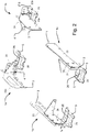
- FIG. 1 A window with an embodiment of the bracket assembly according to the invention comprising a metal bracket and a sacrificial anode is shown in Fig. 1 and the bracket assemblies are shown alone in Fig. 2
- a bracket assembly is provided at each of the corners of the window and is denoted 1a, 1b, 1c and 1d respectively.
- Each of the window bracket assemblies 1a-1d comprises a bracket and a sacrificial anode 23, 24, 25.
- the metal bracket comprises several bracket elements, i.e. a base element 3 provided with sacrificial anode 23, a leg element 4 provided with sacrificial anode 24 and an angle element 5 provided with sacrificial anode 25.
- the base element 3 is placed in parallel to one leg of the leg element 4.
- the sacrificial anodes 23, 24 have the same circumferential shapes as the base element 3 and the leg element 4, respectively, and each cover a main surface of the metal bracket.
- the sacrificial anode 24 covering the leg element 4 is also following its surface geometry as it is also bent in an angle.
- the sacrificial anode 23 covering the base element 3 on bracket assembly 1c and 1d is not completely following the surface geometry of the base element 3. As a part of the surface of the base element 3 is displaced in the plane, surface contact is only partly obtained.
- the sacrificial anode 23 is shaped such that it follows the surface geometry of a surface of the bracket.
- the base elements 3 in 1a and 1b are divided in two, and likewise is the sacrificial anodes 23a, 23b.
- the sacrificial anode 25 has also been divided in two as the surface is interrupted by a projection.
- a thickness t of the sacrificial anode has also been shown, but has been made larger for illustrative purposes.
- the thickness of the plate for the sacrificial anode used in this embodiment is 0.5 mm, corresponding to 1/6 of the thickness of the base element 3 of the bracket. Different thicknesses may be used as well, depending amongst other things on which environment they are to be used in and on the materials used for the bracket and the anode.
- the sacrificial anodes 23, 24, 25 are provided with through going holes in the same places as the bracket elements 3, 4, 5. This makes it possible to attach the sacrificial anodes 23, 24, 25 to the bracket elements 3, 4, 5 in the same working operation as the attachment of the bracket elements or bracket to the construction or window as the same attachment means, such as screws 8, may fasten both the bracket 3, 4, 5 and the sacrificial anode 23, 24, 25 to the construction, window 6 or a neighbouring bracket.
- the thickness t b is the thickness of the plate material used for the bracket. In this embodiment it is 3 mm, but it may be thicker or thinner.
- the sacrificial anode 23 is provided with attachment members 7 that grip around the base element 3. These attachment members 7 may be dispensed with and the sacrificial anode may be attached to the bracket in the same step as when the bracket is attached to the window frame part.
- the sacrificial anode may be tray shaped and cover the edges of the bracket elements as well.
- the window 6 and the window bracket assembly 1 shown in Figs 1 and 2 are suitable for being used in a ridge constellation, where two windows meet top-to-top, the tops of the windows resting on a ridge beam extending in parallel with the ridge and with the bottoms resting on opposite wall or façade elements, or in the case of installation on substantially flat roofs, on opposite upstands.
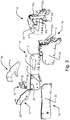
- Fig. 3 shows a different embodiment of a bracket assembly 1a-1f, configured to be used on an openable window.
- the brackets assemblies 1a, 1b, 1c, 1d are configured to be positioned on a window frame in substantially the same way as in Fig 1
- the bracket assemblies 1e, 1f, 1g comprising the brackets 9, 30 are configured to be positioned on a sash of a window and are all provided with sacrificial anodes 29, 20. It will, however, be understood that it is not necessary to provide all brackets, associated with a window, with sacrificial anodes in order to achieve an advantageous effect.
- sacrificial anode 23c is configured to be positioned on a different embodiment of the bracket 3 in Fig. 3 .
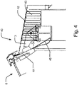
- Fig. 4 shows a cross section of a roof structure 40, provided with a window 6, a flashing element 42 and insulation 43.
- the window comprises a frame 44 and a bracket 3 resting on a beam of a load bearing structure. Between the bracket 3 and the frame 44 a secondary sacrificial anode 45 is positioned.
- the secondary sacrificial anode 45 is in the form of a plate, but it may be in the form of a film or foil as well.
Landscapes
- Chemical & Material Sciences (AREA)
- Engineering & Computer Science (AREA)
- Mechanical Engineering (AREA)
- Materials Engineering (AREA)
- Metallurgy (AREA)
- Organic Chemistry (AREA)
- Architecture (AREA)
- Civil Engineering (AREA)
- Structural Engineering (AREA)
- Prevention Of Electric Corrosion (AREA)
Claims (12)
- Ensemble d'appui de fenêtre (1) destiné à être utilisé en relation avec une fenêtre (6) et une construction, comprenant un appui métallique (3, 4, 5) et au moins une anode sacrificielle (20, 23, 24, 25, 29), l'appui métallique (3, 4, 5) étant placé en contact avec ou à proximité de l'au moins une anode sacrificielle (20 ; 23 ; 24 ; 25 ; 29) et l'appui métallique (3, 4, 5) et l'anode sacrificielle (20 ; 23 ; 24 ; 25 ; 29) ayant au moins un point de connexion mutuelle, pour prolonger la durée de vie de l'appui métallique (3, 4, 5), caractérisé en ce que l'appui métallique (3, 4, 5), qui comprend de préférence plusieurs éléments d'appui (3, 4, 5), comprend une surface principale et des bords adjacents, la surface principale étant une zone de surface non obstruée, avec une surface générale plane, la surface principale qui est en contact avec l'anode sacrificielle (20, 23, 24, 25, 29) étant une surface qui fait face à un côté de l'appui qui est conçu pour être tourné à l'opposé de la construction ou de la fenêtre (6) sur laquelle l'appui est conçu pour être monté, et l'anode sacrificielle (20 ; 23 ; 24 ; 25 ; 29) étant formée à partir d'une plaque et sa géométrie de surface suivant au moins partiellement la géométrie de surface de l'appui métallique (3, 4, 5) à l'état monté, et l'anode sacrificielle (23, 24, 25) étant pourvue de trous traversants aux mêmes endroits que les éléments d'appui (3, 4, 5), ce qui permet de fixer l'anode sacrificielle (23, 24, 25) aux éléments d'appui (3, 4, 5) dans la même opération de travail que la fixation des éléments d'appui (3, 4, 5) ou de l'appui (3, 4, 5) à la construction ou à la fenêtre de sorte que le même moyen de fixation, tel que des vis (8), puisse fixer à la fois l'appui (3, 4, 5) et l'anode sacrificielle (23, 24, 25) à la construction, à la fenêtre (6) ou à un appui voisin,
l'anode sacrificielle (20 ; 23 ; 24 ; 25 ; 29) couvrant la surface principale et éventuellement les bords adjacents. - Ensemble d'appui de fenêtre selon la revendication 1, l'anode sacrificielle (20 ; 23 ; 24 ; 25 ; 29) ayant une épaisseur comprise entre 150 µm et 2 000 µm, de préférence entre 300 µm et 1 000 µm et de préférence encore entre 400 µm et 600 µm.
- Ensemble d'appui de fenêtre (1) selon la revendication 1, l'appui métallique (3, 4, 5) ayant une épaisseur de plaque de 5 mm ou moins, de préférence comprise entre 2 et 4 mm, de préférence encore comprise entre 2,5 mm et 3,5 mm.
- Ensemble d'appui de fenêtre (1) selon l'une quelconque des revendications précédentes, l'anode sacrificielle (20 ; 23 ; 24 ; 25 ; 29) comprenant du zinc, du magnésium et/ou de l'aluminium.
- Ensemble d'appui de fenêtre (1) selon l'une quelconque des revendications précédentes, l'appui métallique (3, 4, 5) étant principalement constitué d'acier ou de fer ou d'autres alliages à base de fer, de préférence d'acier au carbone ou de fer au carbone.
- Ensemble d'appui de fenêtre (1) selon l'une quelconque des revendications précédentes, l'anode sacrificielle (20 ; 23 ; 24 ; 25 ; 29) étant positionnée plus bas dans la série galvanique que l'appui métallique (3, 4, 5).
- Ensemble d'appui de fenêtre (1) selon l'une quelconque des revendications précédentes, l'appui métallique (3, 4, 5) étant pourvu d'un revêtement protecteur, tel qu'un revêtement de zinc et/ou un revêtement de conversion au chromate.
- Ensemble d'appui de fenêtre (1) selon l'une quelconque des revendications précédentes, l'appui métallique (3, 4, 5) et/ou l'anode sacrificielle (20 ; 23 ; 24 ; 25 ; 29) étant pourvu d'au moins un élément de fixation (7) pour l'interconnexion.
- Ensemble d'appui de fenêtre (1) selon l'une quelconque des revendications précédentes, l'anode sacrificielle (20 ; 23 ; 24 ; 25 ; 29) étant positionnée sur le côté conçu pour être un côté froid de l'appui métallique (3, 4, 5).
- Utilisation d'un ensemble d'appui de fenêtre (1) selon l'une quelconque des revendications précédentes en relation avec une fenêtre (6), de préférence une fenêtre de toit.
- Fenêtre pourvue d'un ensemble de support de fenêtre (1) selon l'une quelconque des revendications 1 à 9.
- Fenêtre selon la revendication 11 placée en relation avec une anode sacrificielle secondaire (20 ; 23 ; 24 ; 25 ; 29) s'étendant dans au moins une direction à partir d'un cadre de la fenêtre et étant placée en relation avec l'ensemble d'appui de fenêtre (1) en au moins un point de liaison.
Applications Claiming Priority (1)
| Application Number | Priority Date | Filing Date | Title |
|---|---|---|---|
| DKPA201670392 | 2016-05-31 |
Publications (2)
| Publication Number | Publication Date |
|---|---|
| EP3252256A1 EP3252256A1 (fr) | 2017-12-06 |
| EP3252256B1 true EP3252256B1 (fr) | 2020-12-30 |
Family
ID=59101258
Family Applications (1)
| Application Number | Title | Priority Date | Filing Date |
|---|---|---|---|
| EP17173408.0A Active EP3252256B1 (fr) | 2016-05-31 | 2017-05-30 | Ensemble d'appui de fenêtre |
Country Status (2)
| Country | Link |
|---|---|
| EP (1) | EP3252256B1 (fr) |
| CN (1) | CN207210545U (fr) |
Families Citing this family (5)
| Publication number | Priority date | Publication date | Assignee | Title |
|---|---|---|---|---|
| US11255090B2 (en) * | 2019-01-10 | 2022-02-22 | Vkr Holding A/S | Connector bracket for interconnecting roof windows, a roof window arrangement, and a method for mounting at least two windows in an inclined roof structure |
| DK180351B1 (en) | 2019-01-10 | 2021-01-22 | Vkr Holding As | An end closure for a cladding for a roof window and a roof window arrangement |
| US11002016B2 (en) | 2019-01-10 | 2021-05-11 | Vkr Holding A/S | Connector element for a flashing assembly for use in a roof window arrangement, and a method for weather proofing a roof window arrangement |
| DK180344B1 (en) | 2019-01-10 | 2021-01-15 | Vkr Holding As | A middle flashing assembly and a method for weather-proofing a roof window arrangement |
| JP7558876B2 (ja) * | 2021-04-05 | 2024-10-01 | 株式会社クボタ | 被締結部材及びその塗装用治具並びにその塗装方法 |
Family Cites Families (4)
| Publication number | Priority date | Publication date | Assignee | Title |
|---|---|---|---|---|
| JPS61237788A (ja) * | 1985-04-13 | 1986-10-23 | アルフレッシュ株式会社 | 改装窓枠 |
| JP3849106B2 (ja) * | 1997-03-06 | 2006-11-22 | 株式会社タニタハウジングウェア | 屋根用の瓦敷板 |
| US8562310B1 (en) * | 2004-09-16 | 2013-10-22 | Fluid Metering, Inc. | Chlorination system with corrosion minimizing components |
| CN104533202A (zh) * | 2014-12-22 | 2015-04-22 | 常熟宝成五金制品有限公司 | 耐磨损的合页 |
-
2017
- 2017-05-30 EP EP17173408.0A patent/EP3252256B1/fr active Active
- 2017-05-31 CN CN201720622757.3U patent/CN207210545U/zh not_active Expired - Fee Related
Non-Patent Citations (1)
| Title |
|---|
| None * |
Also Published As
| Publication number | Publication date |
|---|---|
| CN207210545U (zh) | 2018-04-10 |
| EP3252256A1 (fr) | 2017-12-06 |
Similar Documents
| Publication | Publication Date | Title |
|---|---|---|
| EP3252256B1 (fr) | Ensemble d'appui de fenêtre | |
| US20060156648A1 (en) | Apparatus for mounting a solar panel or other article to a roof or other structure | |
| JP3623929B2 (ja) | 外壁仕上げ材用金属製下地材に用いる金属製スペーサと外壁仕上げ材の固定構造 | |
| US20090098345A1 (en) | Polymer-coated construction component and method | |
| US20130326975A1 (en) | Fire protected steel structure and removable panels for fire protection of a steel structures | |
| CN105544875A (zh) | 一种钉盖帽及应用钉盖帽的节点结构 | |
| JP2747249B2 (ja) | 改装窓 | |
| Asif et al. | Embodied energy analysis of aluminium-clad windows | |
| JPH11256372A (ja) | 屋内環境における高強度ボルトとステンレス鋼の異種金属接触腐食防止方法 | |
| JP2005120804A (ja) | 錆や腐食を防止するドア用被せ工法と熱や音が伝達しない結露防止真空扉。 | |
| JP6638601B2 (ja) | 太陽光発電パネル設置構造及び工法 | |
| EP3564460A1 (fr) | Fenêtre de toit avec renforcement dans l'élément châssis supérieur | |
| Nürnberger et al. | Condition of Galfan‐coated open spiral ropes after 15 years in the atmosphere of a brine bath | |
| CN224161615U (zh) | 一种耐老化铝合金门框 | |
| RU45743U1 (ru) | Несущая стеновая панель | |
| US20240240454A1 (en) | Wall assembly for building structures and methods for manufacturing thereof | |
| Maurenbrecher | Corrosion of Metal Ties in Masonry Cladding | |
| CN211817396U (zh) | 一种使用寿命长的钢结构 | |
| JPH10176256A (ja) | スチールハウス部材用めっき鋼板 | |
| JP3165263U (ja) | 鋼材の防食構造 | |
| JP7307324B2 (ja) | 複合構造体 | |
| JPS6014793Y2 (ja) | 耐食性ハンガ−ロ−プ | |
| US20040245767A1 (en) | Sill plates | |
| JPH10176376A (ja) | 耐食性に優れたスチールハウス建造物の施工方法 | |
| JP2000027321A (ja) | 防水シート固定具 |
Legal Events
| Date | Code | Title | Description |
|---|---|---|---|
| PUAI | Public reference made under article 153(3) epc to a published international application that has entered the european phase |
Free format text: ORIGINAL CODE: 0009012 |
|
| STAA | Information on the status of an ep patent application or granted ep patent |
Free format text: STATUS: THE APPLICATION HAS BEEN PUBLISHED |
|
| AK | Designated contracting states |
Kind code of ref document: A1 Designated state(s): AL AT BE BG CH CY CZ DE DK EE ES FI FR GB GR HR HU IE IS IT LI LT LU LV MC MK MT NL NO PL PT RO RS SE SI SK SM TR |
|
| AX | Request for extension of the european patent |
Extension state: BA ME |
|
| STAA | Information on the status of an ep patent application or granted ep patent |
Free format text: STATUS: REQUEST FOR EXAMINATION WAS MADE |
|
| 17P | Request for examination filed |
Effective date: 20180606 |
|
| RBV | Designated contracting states (corrected) |
Designated state(s): AL AT BE BG CH CY CZ DE DK EE ES FI FR GB GR HR HU IE IS IT LI LT LU LV MC MK MT NL NO PL PT RO RS SE SI SK SM TR |
|
| STAA | Information on the status of an ep patent application or granted ep patent |
Free format text: STATUS: EXAMINATION IS IN PROGRESS |
|
| 17Q | First examination report despatched |
Effective date: 20200513 |
|
| GRAP | Despatch of communication of intention to grant a patent |
Free format text: ORIGINAL CODE: EPIDOSNIGR1 |
|
| STAA | Information on the status of an ep patent application or granted ep patent |
Free format text: STATUS: GRANT OF PATENT IS INTENDED |
|
| RIC1 | Information provided on ipc code assigned before grant |
Ipc: C23F 13/20 20060101ALI20200922BHEP Ipc: C23F 13/18 20060101ALI20200922BHEP Ipc: E05D 7/081 20060101ALN20200922BHEP Ipc: C23F 13/14 20060101ALI20200922BHEP Ipc: E05D 9/00 20060101AFI20200922BHEP Ipc: C23F 13/08 20060101ALI20200922BHEP Ipc: E04D 13/03 20060101ALI20200922BHEP Ipc: C23F 13/10 20060101ALI20200922BHEP |
|
| INTG | Intention to grant announced |
Effective date: 20201020 |
|
| GRAS | Grant fee paid |
Free format text: ORIGINAL CODE: EPIDOSNIGR3 |
|
| GRAA | (expected) grant |
Free format text: ORIGINAL CODE: 0009210 |
|
| STAA | Information on the status of an ep patent application or granted ep patent |
Free format text: STATUS: THE PATENT HAS BEEN GRANTED |
|
| AK | Designated contracting states |
Kind code of ref document: B1 Designated state(s): AL AT BE BG CH CY CZ DE DK EE ES FI FR GB GR HR HU IE IS IT LI LT LU LV MC MK MT NL NO PL PT RO RS SE SI SK SM TR |
|
| REG | Reference to a national code |
Ref country code: GB Ref legal event code: FG4D |
|
| REG | Reference to a national code |
Ref country code: AT Ref legal event code: REF Ref document number: 1350074 Country of ref document: AT Kind code of ref document: T Effective date: 20210115 |
|
| REG | Reference to a national code |
Ref country code: DE Ref legal event code: R096 Ref document number: 602017030317 Country of ref document: DE |
|
| REG | Reference to a national code |
Ref country code: IE Ref legal event code: FG4D |
|
| PG25 | Lapsed in a contracting state [announced via postgrant information from national office to epo] |
Ref country code: RS Free format text: LAPSE BECAUSE OF FAILURE TO SUBMIT A TRANSLATION OF THE DESCRIPTION OR TO PAY THE FEE WITHIN THE PRESCRIBED TIME-LIMIT Effective date: 20201230 Ref country code: NO Free format text: LAPSE BECAUSE OF FAILURE TO SUBMIT A TRANSLATION OF THE DESCRIPTION OR TO PAY THE FEE WITHIN THE PRESCRIBED TIME-LIMIT Effective date: 20210330 Ref country code: FI Free format text: LAPSE BECAUSE OF FAILURE TO SUBMIT A TRANSLATION OF THE DESCRIPTION OR TO PAY THE FEE WITHIN THE PRESCRIBED TIME-LIMIT Effective date: 20201230 Ref country code: GR Free format text: LAPSE BECAUSE OF FAILURE TO SUBMIT A TRANSLATION OF THE DESCRIPTION OR TO PAY THE FEE WITHIN THE PRESCRIBED TIME-LIMIT Effective date: 20210331 |
|
| REG | Reference to a national code |
Ref country code: AT Ref legal event code: MK05 Ref document number: 1350074 Country of ref document: AT Kind code of ref document: T Effective date: 20201230 |
|
| PG25 | Lapsed in a contracting state [announced via postgrant information from national office to epo] |
Ref country code: SE Free format text: LAPSE BECAUSE OF FAILURE TO SUBMIT A TRANSLATION OF THE DESCRIPTION OR TO PAY THE FEE WITHIN THE PRESCRIBED TIME-LIMIT Effective date: 20201230 Ref country code: LV Free format text: LAPSE BECAUSE OF FAILURE TO SUBMIT A TRANSLATION OF THE DESCRIPTION OR TO PAY THE FEE WITHIN THE PRESCRIBED TIME-LIMIT Effective date: 20201230 Ref country code: BG Free format text: LAPSE BECAUSE OF FAILURE TO SUBMIT A TRANSLATION OF THE DESCRIPTION OR TO PAY THE FEE WITHIN THE PRESCRIBED TIME-LIMIT Effective date: 20210330 |
|
| REG | Reference to a national code |
Ref country code: NL Ref legal event code: MP Effective date: 20201230 |
|
| PG25 | Lapsed in a contracting state [announced via postgrant information from national office to epo] |
Ref country code: HR Free format text: LAPSE BECAUSE OF FAILURE TO SUBMIT A TRANSLATION OF THE DESCRIPTION OR TO PAY THE FEE WITHIN THE PRESCRIBED TIME-LIMIT Effective date: 20201230 |
|
| REG | Reference to a national code |
Ref country code: LT Ref legal event code: MG9D |
|
| PG25 | Lapsed in a contracting state [announced via postgrant information from national office to epo] |
Ref country code: LT Free format text: LAPSE BECAUSE OF FAILURE TO SUBMIT A TRANSLATION OF THE DESCRIPTION OR TO PAY THE FEE WITHIN THE PRESCRIBED TIME-LIMIT Effective date: 20201230 Ref country code: EE Free format text: LAPSE BECAUSE OF FAILURE TO SUBMIT A TRANSLATION OF THE DESCRIPTION OR TO PAY THE FEE WITHIN THE PRESCRIBED TIME-LIMIT Effective date: 20201230 Ref country code: CZ Free format text: LAPSE BECAUSE OF FAILURE TO SUBMIT A TRANSLATION OF THE DESCRIPTION OR TO PAY THE FEE WITHIN THE PRESCRIBED TIME-LIMIT Effective date: 20201230 Ref country code: PT Free format text: LAPSE BECAUSE OF FAILURE TO SUBMIT A TRANSLATION OF THE DESCRIPTION OR TO PAY THE FEE WITHIN THE PRESCRIBED TIME-LIMIT Effective date: 20210430 Ref country code: RO Free format text: LAPSE BECAUSE OF FAILURE TO SUBMIT A TRANSLATION OF THE DESCRIPTION OR TO PAY THE FEE WITHIN THE PRESCRIBED TIME-LIMIT Effective date: 20201230 Ref country code: SK Free format text: LAPSE BECAUSE OF FAILURE TO SUBMIT A TRANSLATION OF THE DESCRIPTION OR TO PAY THE FEE WITHIN THE PRESCRIBED TIME-LIMIT Effective date: 20201230 |
|
| PG25 | Lapsed in a contracting state [announced via postgrant information from national office to epo] |
Ref country code: AT Free format text: LAPSE BECAUSE OF FAILURE TO SUBMIT A TRANSLATION OF THE DESCRIPTION OR TO PAY THE FEE WITHIN THE PRESCRIBED TIME-LIMIT Effective date: 20201230 Ref country code: PL Free format text: LAPSE BECAUSE OF FAILURE TO SUBMIT A TRANSLATION OF THE DESCRIPTION OR TO PAY THE FEE WITHIN THE PRESCRIBED TIME-LIMIT Effective date: 20201230 |
|
| PG25 | Lapsed in a contracting state [announced via postgrant information from national office to epo] |
Ref country code: IS Free format text: LAPSE BECAUSE OF FAILURE TO SUBMIT A TRANSLATION OF THE DESCRIPTION OR TO PAY THE FEE WITHIN THE PRESCRIBED TIME-LIMIT Effective date: 20210430 |
|
| REG | Reference to a national code |
Ref country code: DE Ref legal event code: R097 Ref document number: 602017030317 Country of ref document: DE |
|
| PG25 | Lapsed in a contracting state [announced via postgrant information from national office to epo] |
Ref country code: IT Free format text: LAPSE BECAUSE OF FAILURE TO SUBMIT A TRANSLATION OF THE DESCRIPTION OR TO PAY THE FEE WITHIN THE PRESCRIBED TIME-LIMIT Effective date: 20201230 Ref country code: AL Free format text: LAPSE BECAUSE OF FAILURE TO SUBMIT A TRANSLATION OF THE DESCRIPTION OR TO PAY THE FEE WITHIN THE PRESCRIBED TIME-LIMIT Effective date: 20201230 |
|
| PLBE | No opposition filed within time limit |
Free format text: ORIGINAL CODE: 0009261 |
|
| STAA | Information on the status of an ep patent application or granted ep patent |
Free format text: STATUS: NO OPPOSITION FILED WITHIN TIME LIMIT |
|
| PG25 | Lapsed in a contracting state [announced via postgrant information from national office to epo] |
Ref country code: DK Free format text: LAPSE BECAUSE OF FAILURE TO SUBMIT A TRANSLATION OF THE DESCRIPTION OR TO PAY THE FEE WITHIN THE PRESCRIBED TIME-LIMIT Effective date: 20201230 |
|
| 26N | No opposition filed |
Effective date: 20211001 |
|
| REG | Reference to a national code |
Ref country code: CH Ref legal event code: PL |
|
| PG25 | Lapsed in a contracting state [announced via postgrant information from national office to epo] |
Ref country code: LU Free format text: LAPSE BECAUSE OF NON-PAYMENT OF DUE FEES Effective date: 20210530 Ref country code: MC Free format text: LAPSE BECAUSE OF FAILURE TO SUBMIT A TRANSLATION OF THE DESCRIPTION OR TO PAY THE FEE WITHIN THE PRESCRIBED TIME-LIMIT Effective date: 20201230 Ref country code: LI Free format text: LAPSE BECAUSE OF NON-PAYMENT OF DUE FEES Effective date: 20210531 Ref country code: CH Free format text: LAPSE BECAUSE OF NON-PAYMENT OF DUE FEES Effective date: 20210531 Ref country code: ES Free format text: LAPSE BECAUSE OF FAILURE TO SUBMIT A TRANSLATION OF THE DESCRIPTION OR TO PAY THE FEE WITHIN THE PRESCRIBED TIME-LIMIT Effective date: 20201230 |
|
| REG | Reference to a national code |
Ref country code: BE Ref legal event code: MM Effective date: 20210531 |
|
| PG25 | Lapsed in a contracting state [announced via postgrant information from national office to epo] |
Ref country code: SI Free format text: LAPSE BECAUSE OF FAILURE TO SUBMIT A TRANSLATION OF THE DESCRIPTION OR TO PAY THE FEE WITHIN THE PRESCRIBED TIME-LIMIT Effective date: 20201230 |
|
| PG25 | Lapsed in a contracting state [announced via postgrant information from national office to epo] |
Ref country code: IE Free format text: LAPSE BECAUSE OF NON-PAYMENT OF DUE FEES Effective date: 20210530 |
|
| PG25 | Lapsed in a contracting state [announced via postgrant information from national office to epo] |
Ref country code: IS Free format text: LAPSE BECAUSE OF FAILURE TO SUBMIT A TRANSLATION OF THE DESCRIPTION OR TO PAY THE FEE WITHIN THE PRESCRIBED TIME-LIMIT Effective date: 20210430 |
|
| PG25 | Lapsed in a contracting state [announced via postgrant information from national office to epo] |
Ref country code: BE Free format text: LAPSE BECAUSE OF NON-PAYMENT OF DUE FEES Effective date: 20210531 |
|
| PGFP | Annual fee paid to national office [announced via postgrant information from national office to epo] |
Ref country code: FR Payment date: 20220422 Year of fee payment: 6 Ref country code: DE Payment date: 20220406 Year of fee payment: 6 |
|
| PG25 | Lapsed in a contracting state [announced via postgrant information from national office to epo] |
Ref country code: HU Free format text: LAPSE BECAUSE OF FAILURE TO SUBMIT A TRANSLATION OF THE DESCRIPTION OR TO PAY THE FEE WITHIN THE PRESCRIBED TIME-LIMIT; INVALID AB INITIO Effective date: 20170530 |
|
| PG25 | Lapsed in a contracting state [announced via postgrant information from national office to epo] |
Ref country code: NL Free format text: LAPSE BECAUSE OF NON-PAYMENT OF DUE FEES Effective date: 20201230 Ref country code: CY Free format text: LAPSE BECAUSE OF FAILURE TO SUBMIT A TRANSLATION OF THE DESCRIPTION OR TO PAY THE FEE WITHIN THE PRESCRIBED TIME-LIMIT Effective date: 20201230 |
|
| PG25 | Lapsed in a contracting state [announced via postgrant information from national office to epo] |
Ref country code: SM Free format text: LAPSE BECAUSE OF FAILURE TO SUBMIT A TRANSLATION OF THE DESCRIPTION OR TO PAY THE FEE WITHIN THE PRESCRIBED TIME-LIMIT Effective date: 20201230 |
|
| REG | Reference to a national code |
Ref country code: DE Ref legal event code: R119 Ref document number: 602017030317 Country of ref document: DE |
|
| PG25 | Lapsed in a contracting state [announced via postgrant information from national office to epo] |
Ref country code: MK Free format text: LAPSE BECAUSE OF FAILURE TO SUBMIT A TRANSLATION OF THE DESCRIPTION OR TO PAY THE FEE WITHIN THE PRESCRIBED TIME-LIMIT Effective date: 20201230 Ref country code: DE Free format text: LAPSE BECAUSE OF NON-PAYMENT OF DUE FEES Effective date: 20231201 |
|
| PG25 | Lapsed in a contracting state [announced via postgrant information from national office to epo] |
Ref country code: FR Free format text: LAPSE BECAUSE OF NON-PAYMENT OF DUE FEES Effective date: 20230531 |
|
| PG25 | Lapsed in a contracting state [announced via postgrant information from national office to epo] |
Ref country code: TR Free format text: LAPSE BECAUSE OF FAILURE TO SUBMIT A TRANSLATION OF THE DESCRIPTION OR TO PAY THE FEE WITHIN THE PRESCRIBED TIME-LIMIT Effective date: 20201230 |
|
| PG25 | Lapsed in a contracting state [announced via postgrant information from national office to epo] |
Ref country code: MT Free format text: LAPSE BECAUSE OF FAILURE TO SUBMIT A TRANSLATION OF THE DESCRIPTION OR TO PAY THE FEE WITHIN THE PRESCRIBED TIME-LIMIT Effective date: 20201230 |
|
| PGFP | Annual fee paid to national office [announced via postgrant information from national office to epo] |
Ref country code: GB Payment date: 20260312 Year of fee payment: 10 |