EP3252296B1 - Kraftstoffversorgungssystem und -verfahren für schiffsmotor - Google Patents
Kraftstoffversorgungssystem und -verfahren für schiffsmotor Download PDFInfo
- Publication number
- EP3252296B1 EP3252296B1 EP15880207.4A EP15880207A EP3252296B1 EP 3252296 B1 EP3252296 B1 EP 3252296B1 EP 15880207 A EP15880207 A EP 15880207A EP 3252296 B1 EP3252296 B1 EP 3252296B1
- Authority
- EP
- European Patent Office
- Prior art keywords
- lng
- pressure
- pressure pump
- engine
- storage tank
- Prior art date
- Legal status (The legal status is an assumption and is not a legal conclusion. Google has not performed a legal analysis and makes no representation as to the accuracy of the status listed.)
- Active
Links
Images
Classifications
-
- B—PERFORMING OPERATIONS; TRANSPORTING
- B63—SHIPS OR OTHER WATERBORNE VESSELS; RELATED EQUIPMENT
- B63H—MARINE PROPULSION OR STEERING
- B63H21/00—Use of propulsion power plant or units on vessels
- B63H21/38—Apparatus or methods specially adapted for use on marine vessels, for handling power plant or unit liquids, e.g. lubricants, coolants, fuels or the like
-
- B—PERFORMING OPERATIONS; TRANSPORTING
- B63—SHIPS OR OTHER WATERBORNE VESSELS; RELATED EQUIPMENT
- B63B—SHIPS OR OTHER WATERBORNE VESSELS; EQUIPMENT FOR SHIPPING
- B63B25/00—Load-accommodating arrangements, e.g. stowing, trimming; Vessels characterised thereby
- B63B25/02—Load-accommodating arrangements, e.g. stowing, trimming; Vessels characterised thereby for bulk goods
- B63B25/08—Load-accommodating arrangements, e.g. stowing, trimming; Vessels characterised thereby for bulk goods fluid
- B63B25/12—Load-accommodating arrangements, e.g. stowing, trimming; Vessels characterised thereby for bulk goods fluid closed
- B63B25/14—Load-accommodating arrangements, e.g. stowing, trimming; Vessels characterised thereby for bulk goods fluid closed pressurised
-
- B—PERFORMING OPERATIONS; TRANSPORTING
- B63—SHIPS OR OTHER WATERBORNE VESSELS; RELATED EQUIPMENT
- B63H—MARINE PROPULSION OR STEERING
- B63H21/00—Use of propulsion power plant or units on vessels
- B63H21/12—Use of propulsion power plant or units on vessels the vessels being motor-driven
- B63H21/14—Use of propulsion power plant or units on vessels the vessels being motor-driven relating to internal-combustion engines
-
- F—MECHANICAL ENGINEERING; LIGHTING; HEATING; WEAPONS; BLASTING
- F02—COMBUSTION ENGINES; HOT-GAS OR COMBUSTION-PRODUCT ENGINE PLANTS
- F02B—INTERNAL-COMBUSTION PISTON ENGINES; COMBUSTION ENGINES IN GENERAL
- F02B73/00—Combinations of two or more engines, not otherwise provided for
-
- F—MECHANICAL ENGINEERING; LIGHTING; HEATING; WEAPONS; BLASTING
- F02—COMBUSTION ENGINES; HOT-GAS OR COMBUSTION-PRODUCT ENGINE PLANTS
- F02M—SUPPLYING COMBUSTION ENGINES IN GENERAL WITH COMBUSTIBLE MIXTURES OR CONSTITUENTS THEREOF
- F02M21/00—Apparatus for supplying engines with non-liquid fuels, e.g. gaseous fuels stored in liquid form
- F02M21/02—Apparatus for supplying engines with non-liquid fuels, e.g. gaseous fuels stored in liquid form for gaseous fuels
-
- F—MECHANICAL ENGINEERING; LIGHTING; HEATING; WEAPONS; BLASTING
- F02—COMBUSTION ENGINES; HOT-GAS OR COMBUSTION-PRODUCT ENGINE PLANTS
- F02M—SUPPLYING COMBUSTION ENGINES IN GENERAL WITH COMBUSTIBLE MIXTURES OR CONSTITUENTS THEREOF
- F02M21/00—Apparatus for supplying engines with non-liquid fuels, e.g. gaseous fuels stored in liquid form
- F02M21/02—Apparatus for supplying engines with non-liquid fuels, e.g. gaseous fuels stored in liquid form for gaseous fuels
- F02M21/0218—Details on the gaseous fuel supply system, e.g. tanks, valves, pipes, pumps, rails, injectors or mixers
- F02M21/023—Valves; Pressure or flow regulators in the fuel supply or return system
- F02M21/0239—Pressure or flow regulators therefor
-
- F—MECHANICAL ENGINEERING; LIGHTING; HEATING; WEAPONS; BLASTING
- F02—COMBUSTION ENGINES; HOT-GAS OR COMBUSTION-PRODUCT ENGINE PLANTS
- F02M—SUPPLYING COMBUSTION ENGINES IN GENERAL WITH COMBUSTIBLE MIXTURES OR CONSTITUENTS THEREOF
- F02M21/00—Apparatus for supplying engines with non-liquid fuels, e.g. gaseous fuels stored in liquid form
- F02M21/02—Apparatus for supplying engines with non-liquid fuels, e.g. gaseous fuels stored in liquid form for gaseous fuels
- F02M21/0218—Details on the gaseous fuel supply system, e.g. tanks, valves, pipes, pumps, rails, injectors or mixers
- F02M21/0287—Details on the gaseous fuel supply system, e.g. tanks, valves, pipes, pumps, rails, injectors or mixers characterised by the transition from liquid to gaseous phase ; Injection in liquid phase; Cooling and low temperature storage
-
- F—MECHANICAL ENGINEERING; LIGHTING; HEATING; WEAPONS; BLASTING
- F02—COMBUSTION ENGINES; HOT-GAS OR COMBUSTION-PRODUCT ENGINE PLANTS
- F02M—SUPPLYING COMBUSTION ENGINES IN GENERAL WITH COMBUSTIBLE MIXTURES OR CONSTITUENTS THEREOF
- F02M37/00—Apparatus or systems for feeding liquid fuel from storage containers to carburettors or fuel-injection apparatus; Arrangements for purifying liquid fuel specially adapted for, or arranged on, internal-combustion engines
- F02M37/04—Feeding by means of driven pumps
-
- F—MECHANICAL ENGINEERING; LIGHTING; HEATING; WEAPONS; BLASTING
- F17—STORING OR DISTRIBUTING GASES OR LIQUIDS
- F17C—VESSELS FOR CONTAINING OR STORING COMPRESSED, LIQUEFIED OR SOLIDIFIED GASES; FIXED-CAPACITY GAS-HOLDERS; FILLING VESSELS WITH, OR DISCHARGING FROM VESSELS, COMPRESSED, LIQUEFIED, OR SOLIDIFIED GASES
- F17C13/00—Details of vessels or of the filling or discharging of vessels
- F17C13/02—Special adaptations of indicating, measuring, or monitoring equipment
- F17C13/025—Special adaptations of indicating, measuring, or monitoring equipment having the pressure as the parameter
-
- F—MECHANICAL ENGINEERING; LIGHTING; HEATING; WEAPONS; BLASTING
- F17—STORING OR DISTRIBUTING GASES OR LIQUIDS
- F17C—VESSELS FOR CONTAINING OR STORING COMPRESSED, LIQUEFIED OR SOLIDIFIED GASES; FIXED-CAPACITY GAS-HOLDERS; FILLING VESSELS WITH, OR DISCHARGING FROM VESSELS, COMPRESSED, LIQUEFIED, OR SOLIDIFIED GASES
- F17C13/00—Details of vessels or of the filling or discharging of vessels
- F17C13/02—Special adaptations of indicating, measuring, or monitoring equipment
- F17C13/026—Special adaptations of indicating, measuring, or monitoring equipment having the temperature as the parameter
-
- F—MECHANICAL ENGINEERING; LIGHTING; HEATING; WEAPONS; BLASTING
- F17—STORING OR DISTRIBUTING GASES OR LIQUIDS
- F17C—VESSELS FOR CONTAINING OR STORING COMPRESSED, LIQUEFIED OR SOLIDIFIED GASES; FIXED-CAPACITY GAS-HOLDERS; FILLING VESSELS WITH, OR DISCHARGING FROM VESSELS, COMPRESSED, LIQUEFIED, OR SOLIDIFIED GASES
- F17C3/00—Vessels not under pressure
- F17C3/02—Vessels not under pressure with provision for thermal insulation
- F17C3/022—Land-based bulk storage containers
-
- F—MECHANICAL ENGINEERING; LIGHTING; HEATING; WEAPONS; BLASTING
- F17—STORING OR DISTRIBUTING GASES OR LIQUIDS
- F17C—VESSELS FOR CONTAINING OR STORING COMPRESSED, LIQUEFIED OR SOLIDIFIED GASES; FIXED-CAPACITY GAS-HOLDERS; FILLING VESSELS WITH, OR DISCHARGING FROM VESSELS, COMPRESSED, LIQUEFIED, OR SOLIDIFIED GASES
- F17C3/00—Vessels not under pressure
- F17C3/02—Vessels not under pressure with provision for thermal insulation
- F17C3/025—Bulk storage in barges or on ships
-
- F—MECHANICAL ENGINEERING; LIGHTING; HEATING; WEAPONS; BLASTING
- F17—STORING OR DISTRIBUTING GASES OR LIQUIDS
- F17C—VESSELS FOR CONTAINING OR STORING COMPRESSED, LIQUEFIED OR SOLIDIFIED GASES; FIXED-CAPACITY GAS-HOLDERS; FILLING VESSELS WITH, OR DISCHARGING FROM VESSELS, COMPRESSED, LIQUEFIED, OR SOLIDIFIED GASES
- F17C9/00—Methods or apparatus for discharging liquefied or solidified gases from vessels not under pressure
-
- F—MECHANICAL ENGINEERING; LIGHTING; HEATING; WEAPONS; BLASTING
- F17—STORING OR DISTRIBUTING GASES OR LIQUIDS
- F17C—VESSELS FOR CONTAINING OR STORING COMPRESSED, LIQUEFIED OR SOLIDIFIED GASES; FIXED-CAPACITY GAS-HOLDERS; FILLING VESSELS WITH, OR DISCHARGING FROM VESSELS, COMPRESSED, LIQUEFIED, OR SOLIDIFIED GASES
- F17C9/00—Methods or apparatus for discharging liquefied or solidified gases from vessels not under pressure
- F17C9/02—Methods or apparatus for discharging liquefied or solidified gases from vessels not under pressure with change of state, e.g. vaporisation
-
- F—MECHANICAL ENGINEERING; LIGHTING; HEATING; WEAPONS; BLASTING
- F02—COMBUSTION ENGINES; HOT-GAS OR COMBUSTION-PRODUCT ENGINE PLANTS
- F02M—SUPPLYING COMBUSTION ENGINES IN GENERAL WITH COMBUSTIBLE MIXTURES OR CONSTITUENTS THEREOF
- F02M21/00—Apparatus for supplying engines with non-liquid fuels, e.g. gaseous fuels stored in liquid form
- F02M21/02—Apparatus for supplying engines with non-liquid fuels, e.g. gaseous fuels stored in liquid form for gaseous fuels
- F02M21/0203—Apparatus for supplying engines with non-liquid fuels, e.g. gaseous fuels stored in liquid form for gaseous fuels characterised by the type of gaseous fuel
- F02M21/0215—Mixtures of gaseous fuels; Natural gas; Biogas; Mine gas; Landfill gas
-
- F—MECHANICAL ENGINEERING; LIGHTING; HEATING; WEAPONS; BLASTING
- F02—COMBUSTION ENGINES; HOT-GAS OR COMBUSTION-PRODUCT ENGINE PLANTS
- F02M—SUPPLYING COMBUSTION ENGINES IN GENERAL WITH COMBUSTIBLE MIXTURES OR CONSTITUENTS THEREOF
- F02M21/00—Apparatus for supplying engines with non-liquid fuels, e.g. gaseous fuels stored in liquid form
- F02M21/02—Apparatus for supplying engines with non-liquid fuels, e.g. gaseous fuels stored in liquid form for gaseous fuels
- F02M21/0218—Details on the gaseous fuel supply system, e.g. tanks, valves, pipes, pumps, rails, injectors or mixers
- F02M21/0221—Fuel storage reservoirs, e.g. cryogenic tanks
-
- F—MECHANICAL ENGINEERING; LIGHTING; HEATING; WEAPONS; BLASTING
- F02—COMBUSTION ENGINES; HOT-GAS OR COMBUSTION-PRODUCT ENGINE PLANTS
- F02M—SUPPLYING COMBUSTION ENGINES IN GENERAL WITH COMBUSTIBLE MIXTURES OR CONSTITUENTS THEREOF
- F02M21/00—Apparatus for supplying engines with non-liquid fuels, e.g. gaseous fuels stored in liquid form
- F02M21/02—Apparatus for supplying engines with non-liquid fuels, e.g. gaseous fuels stored in liquid form for gaseous fuels
- F02M21/0218—Details on the gaseous fuel supply system, e.g. tanks, valves, pipes, pumps, rails, injectors or mixers
- F02M21/0245—High pressure fuel supply systems; Rails; Pumps; Arrangement of valves
-
- F—MECHANICAL ENGINEERING; LIGHTING; HEATING; WEAPONS; BLASTING
- F02—COMBUSTION ENGINES; HOT-GAS OR COMBUSTION-PRODUCT ENGINE PLANTS
- F02M—SUPPLYING COMBUSTION ENGINES IN GENERAL WITH COMBUSTIBLE MIXTURES OR CONSTITUENTS THEREOF
- F02M21/00—Apparatus for supplying engines with non-liquid fuels, e.g. gaseous fuels stored in liquid form
- F02M21/02—Apparatus for supplying engines with non-liquid fuels, e.g. gaseous fuels stored in liquid form for gaseous fuels
- F02M21/06—Apparatus for de-liquefying, e.g. by heating
-
- F—MECHANICAL ENGINEERING; LIGHTING; HEATING; WEAPONS; BLASTING
- F17—STORING OR DISTRIBUTING GASES OR LIQUIDS
- F17C—VESSELS FOR CONTAINING OR STORING COMPRESSED, LIQUEFIED OR SOLIDIFIED GASES; FIXED-CAPACITY GAS-HOLDERS; FILLING VESSELS WITH, OR DISCHARGING FROM VESSELS, COMPRESSED, LIQUEFIED, OR SOLIDIFIED GASES
- F17C2250/00—Accessories; Control means; Indicating, measuring or monitoring of parameters
- F17C2250/04—Indicating or measuring of parameters as input values
- F17C2250/0404—Parameters indicated or measured
- F17C2250/0439—Temperature
-
- F—MECHANICAL ENGINEERING; LIGHTING; HEATING; WEAPONS; BLASTING
- F17—STORING OR DISTRIBUTING GASES OR LIQUIDS
- F17C—VESSELS FOR CONTAINING OR STORING COMPRESSED, LIQUEFIED OR SOLIDIFIED GASES; FIXED-CAPACITY GAS-HOLDERS; FILLING VESSELS WITH, OR DISCHARGING FROM VESSELS, COMPRESSED, LIQUEFIED, OR SOLIDIFIED GASES
- F17C2250/00—Accessories; Control means; Indicating, measuring or monitoring of parameters
- F17C2250/06—Controlling or regulating of parameters as output values
- F17C2250/0605—Parameters
- F17C2250/061—Level of content in the vessel
-
- F—MECHANICAL ENGINEERING; LIGHTING; HEATING; WEAPONS; BLASTING
- F17—STORING OR DISTRIBUTING GASES OR LIQUIDS
- F17C—VESSELS FOR CONTAINING OR STORING COMPRESSED, LIQUEFIED OR SOLIDIFIED GASES; FIXED-CAPACITY GAS-HOLDERS; FILLING VESSELS WITH, OR DISCHARGING FROM VESSELS, COMPRESSED, LIQUEFIED, OR SOLIDIFIED GASES
- F17C2250/00—Accessories; Control means; Indicating, measuring or monitoring of parameters
- F17C2250/06—Controlling or regulating of parameters as output values
- F17C2250/0605—Parameters
- F17C2250/0636—Flow or movement of content
-
- F—MECHANICAL ENGINEERING; LIGHTING; HEATING; WEAPONS; BLASTING
- F17—STORING OR DISTRIBUTING GASES OR LIQUIDS
- F17C—VESSELS FOR CONTAINING OR STORING COMPRESSED, LIQUEFIED OR SOLIDIFIED GASES; FIXED-CAPACITY GAS-HOLDERS; FILLING VESSELS WITH, OR DISCHARGING FROM VESSELS, COMPRESSED, LIQUEFIED, OR SOLIDIFIED GASES
- F17C2260/00—Purposes of gas storage and gas handling
- F17C2260/02—Improving properties related to fluid or fluid transfer
- F17C2260/021—Avoiding over pressurising
-
- F—MECHANICAL ENGINEERING; LIGHTING; HEATING; WEAPONS; BLASTING
- F17—STORING OR DISTRIBUTING GASES OR LIQUIDS
- F17C—VESSELS FOR CONTAINING OR STORING COMPRESSED, LIQUEFIED OR SOLIDIFIED GASES; FIXED-CAPACITY GAS-HOLDERS; FILLING VESSELS WITH, OR DISCHARGING FROM VESSELS, COMPRESSED, LIQUEFIED, OR SOLIDIFIED GASES
- F17C2265/00—Effects achieved by gas storage or gas handling
- F17C2265/06—Fluid distribution
- F17C2265/066—Fluid distribution for feeding engines for propulsion
-
- F—MECHANICAL ENGINEERING; LIGHTING; HEATING; WEAPONS; BLASTING
- F25—REFRIGERATION OR COOLING; COMBINED HEATING AND REFRIGERATION SYSTEMS; HEAT PUMP SYSTEMS; MANUFACTURE OR STORAGE OF ICE; LIQUEFACTION SOLIDIFICATION OF GASES
- F25B—REFRIGERATION MACHINES, PLANTS OR SYSTEMS; COMBINED HEATING AND REFRIGERATION SYSTEMS; HEAT PUMP SYSTEMS
- F25B2600/00—Control issues
- F25B2600/05—Refrigerant levels
-
- F—MECHANICAL ENGINEERING; LIGHTING; HEATING; WEAPONS; BLASTING
- F25—REFRIGERATION OR COOLING; COMBINED HEATING AND REFRIGERATION SYSTEMS; HEAT PUMP SYSTEMS; MANUFACTURE OR STORAGE OF ICE; LIQUEFACTION SOLIDIFICATION OF GASES
- F25B—REFRIGERATION MACHINES, PLANTS OR SYSTEMS; COMBINED HEATING AND REFRIGERATION SYSTEMS; HEAT PUMP SYSTEMS
- F25B2600/00—Control issues
- F25B2600/13—Pump speed control
-
- F—MECHANICAL ENGINEERING; LIGHTING; HEATING; WEAPONS; BLASTING
- F25—REFRIGERATION OR COOLING; COMBINED HEATING AND REFRIGERATION SYSTEMS; HEAT PUMP SYSTEMS; MANUFACTURE OR STORAGE OF ICE; LIQUEFACTION SOLIDIFICATION OF GASES
- F25B—REFRIGERATION MACHINES, PLANTS OR SYSTEMS; COMBINED HEATING AND REFRIGERATION SYSTEMS; HEAT PUMP SYSTEMS
- F25B2600/00—Control issues
- F25B2600/25—Control of valves
-
- Y—GENERAL TAGGING OF NEW TECHNOLOGICAL DEVELOPMENTS; GENERAL TAGGING OF CROSS-SECTIONAL TECHNOLOGIES SPANNING OVER SEVERAL SECTIONS OF THE IPC; TECHNICAL SUBJECTS COVERED BY FORMER USPC CROSS-REFERENCE ART COLLECTIONS [XRACs] AND DIGESTS
- Y02—TECHNOLOGIES OR APPLICATIONS FOR MITIGATION OR ADAPTATION AGAINST CLIMATE CHANGE
- Y02T—CLIMATE CHANGE MITIGATION TECHNOLOGIES RELATED TO TRANSPORTATION
- Y02T10/00—Road transport of goods or passengers
- Y02T10/10—Internal combustion engine [ICE] based vehicles
- Y02T10/30—Use of alternative fuels, e.g. biofuels
-
- Y—GENERAL TAGGING OF NEW TECHNOLOGICAL DEVELOPMENTS; GENERAL TAGGING OF CROSS-SECTIONAL TECHNOLOGIES SPANNING OVER SEVERAL SECTIONS OF THE IPC; TECHNICAL SUBJECTS COVERED BY FORMER USPC CROSS-REFERENCE ART COLLECTIONS [XRACs] AND DIGESTS
- Y02—TECHNOLOGIES OR APPLICATIONS FOR MITIGATION OR ADAPTATION AGAINST CLIMATE CHANGE
- Y02T—CLIMATE CHANGE MITIGATION TECHNOLOGIES RELATED TO TRANSPORTATION
- Y02T70/00—Maritime or waterways transport
- Y02T70/50—Measures to reduce greenhouse gas emissions related to the propulsion system
- Y02T70/5218—Less carbon-intensive fuels, e.g. natural gas, biofuels
Definitions
- the present invention relates to a fuel supply system and method for a ship engine, and, more particularly, to a fuel supply system and method for a ship engine in which LNG is delivered from an LNG storage tank of a ship to a high-pressure pump by a submerged pump and then pressurized to a high pressure by high-pressure pump, followed by re-gasifying the LNG pressurized by the high-pressure pump and supplying the re-gasified LNG to the ship engine, wherein LNG upstream of the high-pressure pump is returned to the LNG storage tank to secure a minimum flow rate of the submerged pump, and a flow rate of LNG to be returned is regulated to control a temperature of LNG in front of the high-pressure pump, thereby preventing boil-off gas from flowing into the high-pressure pump.
- LNG liquefied natural gas
- LPG liquefied petroleum gas
- LNG liquefied natural gas
- LNG is a colorless transparent liquid which can be obtained by cooling natural gas containing methane as a main component to about -162°C and has a volume of about 1/600 that of natural gas.
- LNG carriers are used to transport (carry) LNG by sea.
- DFDE dual fuel diesel electric engine
- KR 2012 0092323 discloses a fuel supply system comprising a high-pressure pump receiving LNG from a LNG storage tank.
- US 2014/261327 discloses a fuel supply system for supplying a liquid fuel.
- a fuel supply system for a ship engine is according to claim 1.
- the fuel supply system further includes: a fuel supply channel for supplying LNG from the LNG storage tank to the engine; and a vaporizer disposed in the fuel supply channel, re-gasifying pressurized LNG from the high-pressure pump, and supplying re-gasified LNG to the engine.
- the engine is a high-pressure gas injection engine fueled by a high-pressure gas compressed to a high pressure of 150 bar to 400 bar.
- the LNG storage tank is a pressure-resistant tank and has a design pressure set to retain BOG or flash gas generated in the pressure-resistant tank during operation of the ship.
- a fuel supply method for a ship engine is according to claim 5.
- the engine is a high-pressure gas injection engine fueled by a high-pressure gas compressed to a high pressure of 150 bar to 400 bar.
- the present invention provides a fuel supply system for a ship engine in which LNG is delivered from an LNG storage tank of a ship to a high-pressure pump by a submerged pump and then pressurized to a high pressure by high-pressure pump, followed by re-gasifying the LNG pressurized by the high-pressure pump and supplying the re-gasified LNG to the ship engine, wherein LNG upstream of the high-pressure pump is returned to the LNG storage tank to secure a minimum flow rate of the submerged pump, and a flow rate of LNG to be returned is regulated to control a temperature of LNG in front of the high-pressure pump. Since LNG in front of the high-pressure pump can remain supercooled through control of the flow rate of LNG returned to the LNG storage tank, it is possible to prevent boil-off gas from flowing into the high-pressure pump, thereby preventing system failure and enabling smooth fuel supply.
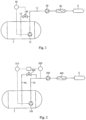
- Fig. 1 is a diagram of an exemplary system for supplying LNG to a ship engine.
- LNG stored in a storage tank T is pumped to a high-pressure pump 20 provided in a supply channel L1 by a delivery pump 10.
- the LNG pressurized by the high-pressure pump 20 is re-gasified by a vaporizer 30 and supplied to a ship engine E as fuel.
- the system is provided with a return channel L2 for returning LNG to the storage tank T.
- the amount of LNG returned to the tank through the return channel L2 may be regulated by controlling a valve 40 disposed in the return channel L2 through a flow controller 50 based on the amount of current consumed by the delivery pump 10.
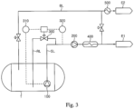
- Fig. 2 is a schematic diagram of a fuel supply system for a ship engine according to one embodiment of the present invention, which is an improvement of the aforementioned fuel supply system.
- a fuel supply system includes a submerged pump 100 disposed in an LNG storage tank T of a ship and supplying LNG to an engine E of the ship, a high-pressure pump 200 receiving LNG from the submerged pump 100 and pressurizing the LNG to a high pressure, and a return channel RL for returning LNG upstream of the high-pressure pump 200 to the LNG storage tank T to secure a minimum flow rate of the submerged pump 100, wherein a temperature of LNG in front of the high-pressure pump 200 is controlled by regulating a flow rate of LNG returned through the return channel RL.
- the temperature of LNG in front of the high-pressure pump 200 is controlled by regulating the flow rate of LNG returned to the LNG storage tank T.
- the return channel RL branches off upstream of the high-pressure pump 200 as close as possible to the high-pressure pump 200, whereby a flow rate of LNG before the high-pressure pump 200 can be as high as possible, and temperature rise due to heat input from the outside can be reduced, thereby preventing generation of boil-off gas.
- the return channel RL is provided with a flow control valve 300 to control the flow rate of LNG returned to the storage tank.
- the flow control valve 300 controls the flow rate of the LNG returned to the LNG storage tank T under control of a flow controller 310 and a temperature controller 320.
- the flow controller 310 controls the flow rate of LNG returned to the LNG storage tank T to secure a minimum flow rate of the submerged pump 100.
- the flow controller 310 may determine the flow rate of LNG required for securing the minimum flow rate of the submerged pump based on the amount of current consumed by the submerged pump 100.
- the temperature controller 320 detects the temperature of LNG in front of the high-pressure pump 200 and determines the flow rate of LNG returned to the LNG storage tank T required to lower the temperature LNG in front of the high-pressure pump 200 below a liquefaction temperature of LNG, that is, to allow LNG in front of the high-pressure pump 200 to remain supercooled.
- the flow control valve 300 determines the higher of two output values obtained based on control signals from the flow controller 310 and the temperature controller 320 as a flow rate of LNG to be returned to the LNG storage tank T, thereby allowing LNG to be returned to the LNG storage tank T at the determined flow rate. That is, even when the flow rate of the submerged pump 100 signaled by the flow controller 310 is higher than the minimum flow rate, if the temperature of LNG in front of the high-pressure pump 200 is higher than a setting point, a flow rate of LNG returned to the storage tank T is increased based on the signal of the temperature controller 320, thereby allowing LNG in front of the high-pressure pump 200 to remain supercooled.
- the flow rate of LNG to be returned is increased, thereby allowing the temperature of LNG in front of the high-pressure pump 200 to be kept low.
- the fuel supply system may further include a control unit (not shown) receiving control signals from the flow controller 310 and the temperature controller 320 and controlling the flow control valve 300 based on the control signals.
- a control unit (not shown) receiving control signals from the flow controller 310 and the temperature controller 320 and controlling the flow control valve 300 based on the control signals.
- a vaporizer 400 receiving and re-gasifying LNG pressurized by the high-pressure pump 200 and supplying the re-gasified LNG to the engine E is disposed in a fuel supply channel SL for supplying LNG from the LNG storage tank T to the engine E.
- the engine E is a high-pressure gas injection engine that is fueled by a high-pressure gas compressed to a high pressure of 150 bar to 400 bar, and may be an engine for propulsion or power generation of the ship, for example, an ME-GI engine.
- An ME-GI engine is a 2-stroke high-pressure natural gas injection engine that was developed to reduce emissions of nitrogen oxide (NO x ) and sulfur oxide (SO x ) and can use gases and oils as fuel, and is fueled by a gas compressed to 150 bar to 400 bar.
- NO x nitrogen oxide
- SO x sulfur oxide
- Such an ME-GI engine can reduce pollutant emissions by 23% for carbon dioxide, 80% for nitrogen compounds, and 95% for sulfur compounds, as compared with a diesel engine of equivalent power output.
- the LNG storage tank T is a pressure-resistant tank.
- a pressure-resistant tank may have a design pressure set to hold BOG or flash gas generated therein during operation of the ship.
- the design pressure of the pressure-resistant tank is set to a gauge pressure of 2 bar or higher, preferably 3 bar to 30 bar.
- the pressure-resistant tank may be an independent storage tank, preferably an IMO C-type tank.
- the fuel supply system may further include a second engine E2 that is fueled by BOG generated in the LNG storage tank T.
- Fig. 3 is a diagram of a modification of the above embodiment, which further includes the second engine.
- the second engine E2 is a low-pressure gas engine that is driven at a lower pressure than the ship engine as described above, that is, the first engine E1.
- BOG can be supplied at a pressure required to operate the second engine using only the internal pressure of the LNG storage tank T without using a separate compressor.
- the second engine E2 may be, for example, a DF engine supplied with fuel gas at 3 bar to 20 bar.
- the fuel supply system may further include a BOG supply line BL for supplying BOG from the LNG storage tank T to the second engine and a heater 500 heating BOG.
- LNG is delivered from an LNG storage tank of a ship to a high-pressure pump by a submerged pump and then pressurized to a high pressure by high-pressure pump, followed by re-gasifying the LNG pressurized by the high-pressure pump and supplying the re-gasified LNG to the ship engine E, wherein LNG upstream of the high-pressure pump 200 is returned to the LNG storage tank T to secure a minimum flow rate of the submerged pump 100, and a flow rate of LNG to be returned is regulated to control a temperature of LNG in front of the high-pressure pump 200, that is, to allow the LNG in front of the high-pressure pump 200 to remain supercooled below a liquefaction temperature of LNG.
- the ship engine E supplied with fuel through the high-pressure pump may be a high-pressure gas injection engine that is fueled by a high-pressure gas compressed to a high pressure of 150 bar to 400 bar, for example, an ME-GI engine.
Landscapes
- Engineering & Computer Science (AREA)
- Chemical & Material Sciences (AREA)
- Mechanical Engineering (AREA)
- Combustion & Propulsion (AREA)
- General Engineering & Computer Science (AREA)
- Chemical Kinetics & Catalysis (AREA)
- General Chemical & Material Sciences (AREA)
- Oil, Petroleum & Natural Gas (AREA)
- Ocean & Marine Engineering (AREA)
- Physics & Mathematics (AREA)
- Thermal Sciences (AREA)
- Filling Or Discharging Of Gas Storage Vessels (AREA)
Claims (6)
- Kraftstoffversorgungssystem für einen Schiffsmotor, wobei das Kraftstoffversorgungssystem Folgendes umfasst;eine Tauchpumpe (100), die dazu ausgelegt ist, zum Versorgen des Schiffsmotors (E; E1) mit LNG in einem LNG-Speichertank (T) eines Schiffs angeordnet zu sein;eine Hochdruckpumpe (200), die dazu ausgelegt ist, LNG von der Tauchpumpe (100) zu empfangen und das LNG unter einen hohen Druck zu setzen; undeinen Rückkanal (RL), der zum Rückleiten von LNG stromaufwärts von der Hochdruckpumpe zum LNG-Speichertank stromaufwärts von der Hochdruckpumpe abzweigt, um eine minimale Durchflussrate der Tauchpumpe (100) sicherzustellen,ein Flusssteuerventil (300), das im Rückkanal (RL) angeordnet ist,eine Flusssteuerung (310), die dazu ausgelegt ist, eine Durchflussrate von zum LNG-Speichertank zurückgeleiteten LNG zu steuern, um eine minimale Durchflussrate der Tauchpumpe (100) sicherzustellen; undeine Temperatursteuerung (320), die dazu ausgelegt ist, vor der Hochdruckpumpe (200) eine Temperatur von LNG zu detektieren und die Durchflussrate von zum LNG-Speichertank zurückgeleitetem LNG zu steuern, um die Temperatur von LNG vor der Hochdruckpumpe unter einer Verflüssigungstemperatur von LNG zu halten;wobei das Flusssteuerventil (300) dazu ausgelegt ist, die Durchflussrate von zum LNG-Speichertank (T) zurückgeleiteten LNG unter Steuerung der Flusssteuerung (310) und der Temperatursteuerung (320) zu steuern, um eine Durchflussrate von durch den Rückkanal (RL) zurückgeleitetem LNG zu regeln, um eine Temperatur von LNG vor der Hochdruckpumpe (200) zu steuern, um zu verhindern, dass Abdampfgas in die Hochdruckpumpe fließt.
- Kraftstoffversorgungssystem nach Anspruch 1, das ferner Folgendes umfasst:einen Kraftstoffversorgungskanal (SL) zum Versorgen des Motors (E; E1) mit LNG aus dem LNG-Speichertank (T); undeinen Verdampfer (400), der im Kraftstoffversorgungskanal angeordnet ist, zum Rückvergasen von unter Druck stehendem LNG aus der Hochdruckpumpe (200) und Versorgen des Motors mit rückvergastem LNG.
- Kraftstoffversorgungssystem nach Anspruch 1 oder 2, wobei der Motor (E; E1) ein Hochdruckgaseinspritzmotor ist, dem ein Hochdruckgas zugeführt wird, das auf einen Hochdruck von 150 bar bis 400 bar verdichtet ist.
- Kraftstoffversorgungssystem nach einem der Ansprüche 1 bis 3, wobei der LNG-Speichertank (T) ein druckbeständiger Tank ist und einen Auslegungsdruck aufweist, der eingestellt ist, um BOG oder Entspannungsgas zu halten, das während des Betriebs des Schiffs im druckbeständigen Tank erzeugt wird.
- Verfahren zum Versorgen eines Schiffsmotors (E; E1) mit Kraftstoff, wobei das Verfahren Folgendes umfasst:Fördern von LNG aus einem LNG-Speichertank (T) eines Schiffs durch eine Tauchpumpe (100) zu einer Hochdruckpumpe (200);Setzen des LNG auf einen hohen Druck durch eine Hochdruckpumpe;Rückvergasen des von der Hochdruckpumpe unter Druck gesetzten LNG; undVersorgen des Schiffsmotors mit dem rückvergastem LNG,wobei LNG mit einer Durchflussrate, die von einer Flusssteuerung gesteuert wird, um eine minimale Durchflussrate der Tauchpumpe (100) sicherzustellen, stromaufwärts von der Hochdruckpumpe (200) zum LNG-Speichertank (T) zurückgeleitet wird,wobei eine Temperatur von LNG vor der Hochdruckpumpe (200) von einer Temperatursteuerung (320) detektiert wird,wobei die Durchflussrate von LNG, das zum LNG-Speichertank zurückzuleiten ist, unter Steuerung der Flusssteuerung (310) und der Temperatursteuerung (320) von einem Flusssteuerventil geregelt wird, das in einem Rückkanal (RL) angeordnet ist, um die Temperatur von LNG vor der Hochdruckpumpe auf unter eine Verflüssigungstemperatur von LNG zu steuern, um die Erzeugung von Abdampfgas am vorderen Ende der Hochdruckpumpe zu verhindern,und wobei der Rückfluss stromaufwärts von der Hochdruckpumpe abgezweigt ist.
- Kraftstoffversorgungsverfahren nach Anspruch 5, wobei der Motor (E; E1) ein Hochdruckgaseinspritzmotor ist, dem ein Hochdruckgas zugeführt wird, das auf einen Hochdruck von 150 bar bis 400 bar verdichtet ist.
Applications Claiming Priority (1)
| Application Number | Priority Date | Filing Date | Title |
|---|---|---|---|
| PCT/KR2015/001029 WO2016122026A1 (ko) | 2015-01-30 | 2015-01-30 | 선박용 엔진의 연료공급 시스템 및 방법 |
Publications (4)
| Publication Number | Publication Date |
|---|---|
| EP3252296A1 EP3252296A1 (de) | 2017-12-06 |
| EP3252296A4 EP3252296A4 (de) | 2018-07-11 |
| EP3252296B1 true EP3252296B1 (de) | 2023-06-07 |
| EP3252296C0 EP3252296C0 (de) | 2023-06-07 |
Family
ID=56543627
Family Applications (1)
| Application Number | Title | Priority Date | Filing Date |
|---|---|---|---|
| EP15880207.4A Active EP3252296B1 (de) | 2015-01-30 | 2015-01-30 | Kraftstoffversorgungssystem und -verfahren für schiffsmotor |
Country Status (8)
| Country | Link |
|---|---|
| US (1) | US10654552B2 (de) |
| EP (1) | EP3252296B1 (de) |
| JP (1) | JP6513815B2 (de) |
| CN (1) | CN107407229B (de) |
| PH (1) | PH12017501357A1 (de) |
| RU (1) | RU2676509C1 (de) |
| SG (1) | SG11201706177PA (de) |
| WO (1) | WO2016122026A1 (de) |
Families Citing this family (11)
| Publication number | Priority date | Publication date | Assignee | Title |
|---|---|---|---|---|
| EP3252296B1 (de) * | 2015-01-30 | 2023-06-07 | Daewoo Shipbuilding & Marine Engineering Co., Ltd. | Kraftstoffversorgungssystem und -verfahren für schiffsmotor |
| US10603549B2 (en) * | 2017-05-06 | 2020-03-31 | Robert Steven Witkoff | Multipurpose low emission submersible engine and aquatic craft using same |
| CN107339610A (zh) * | 2017-08-25 | 2017-11-10 | 成都华气厚普机电设备股份有限公司 | 一种海船lng燃料高压供气系统及其控制方法 |
| CN107339611A (zh) * | 2017-08-25 | 2017-11-10 | 成都华气厚普机电设备股份有限公司 | 一种海船lng燃料低压供气系统及其控制方法 |
| FR3075754B1 (fr) * | 2017-12-22 | 2020-01-03 | Gaztransport Et Technigaz | Navire propulse au gaz liquefie |
| EP3913273A1 (de) * | 2020-05-19 | 2021-11-24 | Burckhardt Compression AG | Brenngasversorgungssystem und verfahren zum versorgen eines hochdruck-gaseinspritzmotors mit brenngas |
| CN112013267B (zh) * | 2020-08-11 | 2022-03-29 | 陕西融科低温设备有限公司 | 一种lng调峰用泵接力方式输出系统及方法 |
| CN112268220A (zh) * | 2020-09-16 | 2021-01-26 | 中海油能源发展股份有限公司 | 一种lng燃料动力船加注方法 |
| CN114183689A (zh) * | 2021-12-29 | 2022-03-15 | 广东华南特种气体研究所有限公司 | 一种气体自动充装系统及控制方法 |
| US11686434B1 (en) * | 2022-02-22 | 2023-06-27 | China Energy Investment Corporation Limited | Submerged multi-mode cryopump for refueling hydrogen, system having the same, and method of using the same |
| CN114954885B (zh) * | 2022-06-20 | 2023-05-26 | 青岛双瑞海洋环境工程股份有限公司 | 氨燃料供应系统和船舶 |
Family Cites Families (33)
| Publication number | Priority date | Publication date | Assignee | Title |
|---|---|---|---|---|
| TW444109B (en) * | 1997-06-20 | 2001-07-01 | Exxon Production Research Co | LNG fuel storage and delivery systems for natural gas powered vehicles |
| FI118680B (fi) * | 2003-12-18 | 2008-02-15 | Waertsilae Finland Oy | Kaasunsyöttöjärjestely vesikulkuneuvossa ja menetelmä kaasun paineen ohjaamiseksi vesikulkuneuvon kaasunsyöttöjärjestelyssä |
| FR2879720B1 (fr) * | 2004-12-17 | 2007-04-06 | Snecma Moteurs Sa | Systeme de compression-evaporation pour gaz liquefie |
| US20080276627A1 (en) | 2007-05-08 | 2008-11-13 | Daewoo Shipbuilding & Marine Engineering Co., Ltd. | Fuel gas supply system and method of a ship |
| BRPI0813637B1 (pt) | 2007-07-09 | 2019-07-09 | Lng Technology Pty Ltd | Processo e sistema para a produção de gás natural liquefeito |
| KR101076266B1 (ko) * | 2007-07-19 | 2011-10-26 | 대우조선해양 주식회사 | Lng 운반선의 연료용 가스 공급 장치 |
| DE102007042158A1 (de) | 2007-09-05 | 2009-03-12 | Man Diesel Se | Gasversorgungsanlage für einen mit gasförmigen Treibstoff betriebenen Verbrennungsmotor |
| US8613201B2 (en) * | 2009-09-08 | 2013-12-24 | Questar Gas Company | Methods and systems for reducing pressure of natural gas and methods and systems of delivering natural gas |
| KR101258932B1 (ko) | 2011-02-11 | 2013-04-29 | 삼성중공업 주식회사 | Lng 재기화 설비 |
| KR101106089B1 (ko) * | 2011-03-11 | 2012-01-18 | 대우조선해양 주식회사 | 고압 천연가스 분사 엔진을 위한 연료 공급 방법 |
| WO2012124886A1 (ko) * | 2011-03-11 | 2012-09-20 | 대우조선해양 주식회사 | 재액화 장치 및 고압 천연가스 분사 엔진을 갖는 해상 구조물의 연료 공급 시스템 |
| JP2014514486A (ja) * | 2011-03-22 | 2014-06-19 | デウ シップビルディング アンド マリーン エンジニアリング カンパニー リミテッド | 高圧天然ガス噴射エンジンのための燃料供給システム及び方法 |
| US20140053600A1 (en) * | 2011-03-22 | 2014-02-27 | Daewoo Shipbuilding & Marine Engineering Co., Ltd. | System for supplying fuel to high-pressure natural gas injection engine having excess evaporation gas consumption means |
| KR101106088B1 (ko) * | 2011-03-22 | 2012-01-18 | 대우조선해양 주식회사 | 고압 천연가스 분사 엔진용 연료 공급 시스템의 재액화 장치에 사용되는 비폭발성 혼합냉매 |
| KR101300703B1 (ko) | 2011-05-04 | 2013-08-26 | 대우조선해양 주식회사 | 천연가스 공급 시스템의 펌프 냉각장치 |
| KR101350803B1 (ko) | 2011-11-14 | 2014-01-15 | 대우조선해양 주식회사 | Lng운송선의 압축기 부하 제어용 모듈 및 이것을 이용한 제어방법 |
| KR101434431B1 (ko) | 2012-01-18 | 2014-09-30 | 삼성중공업 주식회사 | 천연가스 연료공급 시스템 및 천연가스 연료공급 시스템이 탑재된 선박 |
| JP6449649B2 (ja) * | 2012-05-14 | 2019-01-09 | ヒュンダイ ヘビー インダストリーズ カンパニー リミテッド | 液化ガス処理システム及びその方法 |
| JP6026648B2 (ja) * | 2012-05-16 | 2016-11-16 | テーゲーエー、マリン、ガス、エンジニヤリング、ゲーエムベーハー | ガス供給装置 |
| RU128249U1 (ru) | 2012-06-22 | 2013-05-20 | Антон Александрович Сагдаков | Система питания двигателя внутреннего сгорания сжиженным газовым топливом |
| KR101386543B1 (ko) | 2012-10-24 | 2014-04-18 | 대우조선해양 주식회사 | 선박의 증발가스 처리 시스템 |
| US20140174105A1 (en) * | 2012-12-24 | 2014-06-26 | General Electric Campany | Systems and methods for re-condensation of boil-off gas |
| US9482195B2 (en) | 2013-03-14 | 2016-11-01 | GM Global Technology Operations LLC | Fuel supply system for internal combustion engine and methods of using the same |
| KR101277844B1 (ko) * | 2013-03-28 | 2013-06-21 | 현대중공업 주식회사 | Lng 연료 공급 시스템과 이를 구동하는 방법 |
| US9279541B2 (en) * | 2013-04-22 | 2016-03-08 | Air Products And Chemicals, Inc. | Method and system for temperature-controlled gas dispensing |
| CA2909817C (en) * | 2013-04-22 | 2020-10-27 | Chart Inc. | Liquid natural gas cooling on the fly |
| KR20140127460A (ko) * | 2013-04-24 | 2014-11-04 | 현대중공업 주식회사 | Lng 연료 공급 시스템 |
| KR102019269B1 (ko) * | 2013-05-23 | 2019-09-06 | 대우조선해양 주식회사 | 선박용 엔진의 연료공급 시스템 및 방법 |
| US9683518B2 (en) * | 2013-09-17 | 2017-06-20 | Daewoo Shipbuilding & Marine Engineering Co., Ltd. | Fuel gas supply apparatus |
| US9151248B2 (en) * | 2013-09-17 | 2015-10-06 | Daewoo Shipbuilding & Marine Engineering Co., Ltd. | Apparatus and method for transferring inflammable material on marine structure |
| JP2017502208A (ja) * | 2013-11-07 | 2017-01-19 | デウ シップビルディング アンド マリン エンジニアリング カンパニー リミテッド | 船舶用エンジンに燃料を供給する装置及び方法 |
| KR101537279B1 (ko) | 2014-01-06 | 2015-07-16 | 대우조선해양 주식회사 | 선박용 엔진의 연료공급 시스템 및 방법 |
| EP3252296B1 (de) * | 2015-01-30 | 2023-06-07 | Daewoo Shipbuilding & Marine Engineering Co., Ltd. | Kraftstoffversorgungssystem und -verfahren für schiffsmotor |
-
2015
- 2015-01-30 EP EP15880207.4A patent/EP3252296B1/de active Active
- 2015-01-30 US US15/547,446 patent/US10654552B2/en active Active
- 2015-01-30 RU RU2017130498A patent/RU2676509C1/ru active
- 2015-01-30 JP JP2017540086A patent/JP6513815B2/ja active Active
- 2015-01-30 WO PCT/KR2015/001029 patent/WO2016122026A1/ko not_active Ceased
- 2015-01-30 SG SG11201706177PA patent/SG11201706177PA/en unknown
- 2015-01-30 CN CN201580078008.2A patent/CN107407229B/zh active Active
-
2017
- 2017-07-28 PH PH12017501357A patent/PH12017501357A1/en unknown
Also Published As
| Publication number | Publication date |
|---|---|
| WO2016122026A1 (ko) | 2016-08-04 |
| US20180022431A1 (en) | 2018-01-25 |
| SG11201706177PA (en) | 2017-08-30 |
| JP2018511724A (ja) | 2018-04-26 |
| CN107407229B (zh) | 2020-03-13 |
| RU2676509C1 (ru) | 2018-12-29 |
| JP6513815B2 (ja) | 2019-05-15 |
| EP3252296A1 (de) | 2017-12-06 |
| US10654552B2 (en) | 2020-05-19 |
| CN107407229A (zh) | 2017-11-28 |
| EP3252296A4 (de) | 2018-07-11 |
| EP3252296C0 (de) | 2023-06-07 |
| PH12017501357A1 (en) | 2017-12-11 |
Similar Documents
| Publication | Publication Date | Title |
|---|---|---|
| EP3252296B1 (de) | Kraftstoffversorgungssystem und -verfahren für schiffsmotor | |
| EP3252297A1 (de) | Kraftstoffversorgungssystem und -verfahren für schiffsmotor | |
| CN103314208B (zh) | 燃料供给系统和操作燃料供给系统的方法 | |
| US9863370B2 (en) | Method of starting gas delivery from a liquefied gas fuel system to a gas operated engine and a liquefied gas fuel system for a gas operated engine | |
| EP2932147B1 (de) | Verfahren zum füllen eines kraftstofftanks mit verflüssigtem gas und flüssiggasbrennstoffsystem | |
| KR101258926B1 (ko) | 선박 | |
| KR102141086B1 (ko) | 소형 선박용 공간집약적 lng 연료공급시스템 | |
| KR102228063B1 (ko) | 휘발성 유기화합물 처리 시스템 및 선박 | |
| EP3273047B1 (de) | Brenngasversorgungssystem | |
| EP3176071A1 (de) | System und verfahren zur kraftstoffzufuhr | |
| KR102189792B1 (ko) | 액화연료 추진선박의 재액화시스템 | |
| US10767573B2 (en) | Liquefied gas fuel feeding system and a method of operating a power plant of internal combustion engines powered with liquefied gas | |
| KR20160008806A (ko) | 선박의 연료공급 시스템 | |
| KR101537279B1 (ko) | 선박용 엔진의 연료공급 시스템 및 방법 | |
| KR20130035058A (ko) | 연료가스 공급 시스템 및 방법 | |
| KR20150101619A (ko) | 선박의 연료가스 공급시스템 | |
| KR20150086643A (ko) | 선박용 엔진의 연료 공급 시스템 및 방법 | |
| KR101672189B1 (ko) | 연료가스 공급시스템 | |
| KR20150076484A (ko) | 선박의 연료가스 공급시스템 | |
| KR20150062259A (ko) | 선박용 연료 공급 시스템 및 그 제어 방법 | |
| KR20150063259A (ko) | 연료 공급 시스템 및 이를 포함하는 선박 및 연료 공급 방법 | |
| KR20160115241A (ko) | 연료가스 공급시스템 | |
| KR20190036087A (ko) | 연료 공급시스템 | |
| KR20180064777A (ko) | 가스 처리 시스템 및 선박 |
Legal Events
| Date | Code | Title | Description |
|---|---|---|---|
| STAA | Information on the status of an ep patent application or granted ep patent |
Free format text: STATUS: THE INTERNATIONAL PUBLICATION HAS BEEN MADE |
|
| PUAI | Public reference made under article 153(3) epc to a published international application that has entered the european phase |
Free format text: ORIGINAL CODE: 0009012 |
|
| STAA | Information on the status of an ep patent application or granted ep patent |
Free format text: STATUS: REQUEST FOR EXAMINATION WAS MADE |
|
| 17P | Request for examination filed |
Effective date: 20170830 |
|
| AK | Designated contracting states |
Kind code of ref document: A1 Designated state(s): AL AT BE BG CH CY CZ DE DK EE ES FI FR GB GR HR HU IE IS IT LI LT LU LV MC MK MT NL NO PL PT RO RS SE SI SK SM TR |
|
| AX | Request for extension of the european patent |
Extension state: BA ME |
|
| DAX | Request for extension of the european patent (deleted) | ||
| A4 | Supplementary search report drawn up and despatched |
Effective date: 20180612 |
|
| RIC1 | Information provided on ipc code assigned before grant |
Ipc: F02M 37/04 20060101ALI20180606BHEP Ipc: B63H 21/14 20060101ALI20180606BHEP Ipc: F02M 21/02 20060101AFI20180606BHEP |
|
| STAA | Information on the status of an ep patent application or granted ep patent |
Free format text: STATUS: EXAMINATION IS IN PROGRESS |
|
| 17Q | First examination report despatched |
Effective date: 20210628 |
|
| RIC1 | Information provided on ipc code assigned before grant |
Ipc: B63H 21/14 20060101ALI20220912BHEP Ipc: F02B 73/00 20060101ALI20220912BHEP Ipc: F02M 37/04 20060101ALI20220912BHEP Ipc: F02M 21/06 20060101ALI20220912BHEP Ipc: F02M 21/02 20060101AFI20220912BHEP |
|
| GRAP | Despatch of communication of intention to grant a patent |
Free format text: ORIGINAL CODE: EPIDOSNIGR1 |
|
| STAA | Information on the status of an ep patent application or granted ep patent |
Free format text: STATUS: GRANT OF PATENT IS INTENDED |
|
| INTG | Intention to grant announced |
Effective date: 20221206 |
|
| GRAS | Grant fee paid |
Free format text: ORIGINAL CODE: EPIDOSNIGR3 |
|
| GRAA | (expected) grant |
Free format text: ORIGINAL CODE: 0009210 |
|
| STAA | Information on the status of an ep patent application or granted ep patent |
Free format text: STATUS: THE PATENT HAS BEEN GRANTED |
|
| AK | Designated contracting states |
Kind code of ref document: B1 Designated state(s): AL AT BE BG CH CY CZ DE DK EE ES FI FR GB GR HR HU IE IS IT LI LT LU LV MC MK MT NL NO PL PT RO RS SE SI SK SM TR |
|
| REG | Reference to a national code |
Ref country code: GB Ref legal event code: FG4D |
|
| REG | Reference to a national code |
Ref country code: CH Ref legal event code: EP Ref country code: AT Ref legal event code: REF Ref document number: 1575758 Country of ref document: AT Kind code of ref document: T Effective date: 20230615 |
|
| REG | Reference to a national code |
Ref country code: DE Ref legal event code: R096 Ref document number: 602015084067 Country of ref document: DE |
|
| U01 | Request for unitary effect filed |
Effective date: 20230607 |
|
| U07 | Unitary effect registered |
Designated state(s): AT BE BG DE DK EE FI FR IT LT LU LV MT NL PT SE SI Effective date: 20230612 |
|
| REG | Reference to a national code |
Ref country code: NO Ref legal event code: T2 Effective date: 20230607 |
|
| REG | Reference to a national code |
Ref country code: LT Ref legal event code: MG9D |
|
| PG25 | Lapsed in a contracting state [announced via postgrant information from national office to epo] |
Ref country code: ES Free format text: LAPSE BECAUSE OF FAILURE TO SUBMIT A TRANSLATION OF THE DESCRIPTION OR TO PAY THE FEE WITHIN THE PRESCRIBED TIME-LIMIT Effective date: 20230607 |
|
| PG25 | Lapsed in a contracting state [announced via postgrant information from national office to epo] |
Ref country code: RS Free format text: LAPSE BECAUSE OF FAILURE TO SUBMIT A TRANSLATION OF THE DESCRIPTION OR TO PAY THE FEE WITHIN THE PRESCRIBED TIME-LIMIT Effective date: 20230607 Ref country code: HR Free format text: LAPSE BECAUSE OF FAILURE TO SUBMIT A TRANSLATION OF THE DESCRIPTION OR TO PAY THE FEE WITHIN THE PRESCRIBED TIME-LIMIT Effective date: 20230607 Ref country code: GR Free format text: LAPSE BECAUSE OF FAILURE TO SUBMIT A TRANSLATION OF THE DESCRIPTION OR TO PAY THE FEE WITHIN THE PRESCRIBED TIME-LIMIT Effective date: 20230908 |
|
| RAP4 | Party data changed (patent owner data changed or rights of a patent transferred) |
Owner name: HANWHA OCEAN CO., LTD. |
|
| U1H | Name or address of the proprietor changed after the registration of the unitary effect |
Owner name: HANWHA OCEAN CO., LTD.; KR |
|
| PG25 | Lapsed in a contracting state [announced via postgrant information from national office to epo] |
Ref country code: SK Free format text: LAPSE BECAUSE OF FAILURE TO SUBMIT A TRANSLATION OF THE DESCRIPTION OR TO PAY THE FEE WITHIN THE PRESCRIBED TIME-LIMIT Effective date: 20230607 |
|
| PG25 | Lapsed in a contracting state [announced via postgrant information from national office to epo] |
Ref country code: IS Free format text: LAPSE BECAUSE OF FAILURE TO SUBMIT A TRANSLATION OF THE DESCRIPTION OR TO PAY THE FEE WITHIN THE PRESCRIBED TIME-LIMIT Effective date: 20231007 |
|
| PG25 | Lapsed in a contracting state [announced via postgrant information from national office to epo] |
Ref country code: SM Free format text: LAPSE BECAUSE OF FAILURE TO SUBMIT A TRANSLATION OF THE DESCRIPTION OR TO PAY THE FEE WITHIN THE PRESCRIBED TIME-LIMIT Effective date: 20230607 Ref country code: SK Free format text: LAPSE BECAUSE OF FAILURE TO SUBMIT A TRANSLATION OF THE DESCRIPTION OR TO PAY THE FEE WITHIN THE PRESCRIBED TIME-LIMIT Effective date: 20230607 Ref country code: RO Free format text: LAPSE BECAUSE OF FAILURE TO SUBMIT A TRANSLATION OF THE DESCRIPTION OR TO PAY THE FEE WITHIN THE PRESCRIBED TIME-LIMIT Effective date: 20230607 Ref country code: IS Free format text: LAPSE BECAUSE OF FAILURE TO SUBMIT A TRANSLATION OF THE DESCRIPTION OR TO PAY THE FEE WITHIN THE PRESCRIBED TIME-LIMIT Effective date: 20231007 Ref country code: CZ Free format text: LAPSE BECAUSE OF FAILURE TO SUBMIT A TRANSLATION OF THE DESCRIPTION OR TO PAY THE FEE WITHIN THE PRESCRIBED TIME-LIMIT Effective date: 20230607 |
|
| U20 | Renewal fee for the european patent with unitary effect paid |
Year of fee payment: 10 Effective date: 20231229 |
|
| PG25 | Lapsed in a contracting state [announced via postgrant information from national office to epo] |
Ref country code: PL Free format text: LAPSE BECAUSE OF FAILURE TO SUBMIT A TRANSLATION OF THE DESCRIPTION OR TO PAY THE FEE WITHIN THE PRESCRIBED TIME-LIMIT Effective date: 20230607 |
|
| REG | Reference to a national code |
Ref country code: DE Ref legal event code: R097 Ref document number: 602015084067 Country of ref document: DE |
|
| PLBE | No opposition filed within time limit |
Free format text: ORIGINAL CODE: 0009261 |
|
| STAA | Information on the status of an ep patent application or granted ep patent |
Free format text: STATUS: NO OPPOSITION FILED WITHIN TIME LIMIT |
|
| 26N | No opposition filed |
Effective date: 20240308 |
|
| PG25 | Lapsed in a contracting state [announced via postgrant information from national office to epo] |
Ref country code: MC Free format text: LAPSE BECAUSE OF FAILURE TO SUBMIT A TRANSLATION OF THE DESCRIPTION OR TO PAY THE FEE WITHIN THE PRESCRIBED TIME-LIMIT Effective date: 20230607 |
|
| PG25 | Lapsed in a contracting state [announced via postgrant information from national office to epo] |
Ref country code: MC Free format text: LAPSE BECAUSE OF FAILURE TO SUBMIT A TRANSLATION OF THE DESCRIPTION OR TO PAY THE FEE WITHIN THE PRESCRIBED TIME-LIMIT Effective date: 20230607 |
|
| REG | Reference to a national code |
Ref country code: CH Ref legal event code: PL |
|
| GBPC | Gb: european patent ceased through non-payment of renewal fee |
Effective date: 20240130 |
|
| PG25 | Lapsed in a contracting state [announced via postgrant information from national office to epo] |
Ref country code: GB Free format text: LAPSE BECAUSE OF NON-PAYMENT OF DUE FEES Effective date: 20240130 |
|
| PG25 | Lapsed in a contracting state [announced via postgrant information from national office to epo] |
Ref country code: CH Free format text: LAPSE BECAUSE OF NON-PAYMENT OF DUE FEES Effective date: 20240131 |
|
| PG25 | Lapsed in a contracting state [announced via postgrant information from national office to epo] |
Ref country code: GB Free format text: LAPSE BECAUSE OF NON-PAYMENT OF DUE FEES Effective date: 20240130 Ref country code: CH Free format text: LAPSE BECAUSE OF NON-PAYMENT OF DUE FEES Effective date: 20240131 |
|
| PG25 | Lapsed in a contracting state [announced via postgrant information from national office to epo] |
Ref country code: IE Free format text: LAPSE BECAUSE OF NON-PAYMENT OF DUE FEES Effective date: 20240130 |
|
| PG25 | Lapsed in a contracting state [announced via postgrant information from national office to epo] |
Ref country code: IE Free format text: LAPSE BECAUSE OF NON-PAYMENT OF DUE FEES Effective date: 20240130 |
|
| U21 | Renewal fee for the european patent with unitary effect paid with additional fee |
Year of fee payment: 11 Effective date: 20250314 |
|
| PG25 | Lapsed in a contracting state [announced via postgrant information from national office to epo] |
Ref country code: CY Free format text: LAPSE BECAUSE OF FAILURE TO SUBMIT A TRANSLATION OF THE DESCRIPTION OR TO PAY THE FEE WITHIN THE PRESCRIBED TIME-LIMIT; INVALID AB INITIO Effective date: 20150130 |
|
| PG25 | Lapsed in a contracting state [announced via postgrant information from national office to epo] |
Ref country code: HU Free format text: LAPSE BECAUSE OF FAILURE TO SUBMIT A TRANSLATION OF THE DESCRIPTION OR TO PAY THE FEE WITHIN THE PRESCRIBED TIME-LIMIT; INVALID AB INITIO Effective date: 20150130 |
|
| PG25 | Lapsed in a contracting state [announced via postgrant information from national office to epo] |
Ref country code: TR Free format text: LAPSE BECAUSE OF FAILURE TO SUBMIT A TRANSLATION OF THE DESCRIPTION OR TO PAY THE FEE WITHIN THE PRESCRIBED TIME-LIMIT Effective date: 20230607 |
|
| PGFP | Annual fee paid to national office [announced via postgrant information from national office to epo] |
Ref country code: NO Payment date: 20251223 Year of fee payment: 12 |
|
| U20 | Renewal fee for the european patent with unitary effect paid |
Year of fee payment: 12 Effective date: 20260122 |