EP3252331A2 - Reibungsplatte - Google Patents
Reibungsplatte Download PDFInfo
- Publication number
- EP3252331A2 EP3252331A2 EP17172403.2A EP17172403A EP3252331A2 EP 3252331 A2 EP3252331 A2 EP 3252331A2 EP 17172403 A EP17172403 A EP 17172403A EP 3252331 A2 EP3252331 A2 EP 3252331A2
- Authority
- EP
- European Patent Office
- Prior art keywords
- vertexes
- friction
- friction material
- oil
- inner circumference
- Prior art date
- Legal status (The legal status is an assumption and is not a legal conclusion. Google has not performed a legal analysis and makes no representation as to the accuracy of the status listed.)
- Granted
Links
Images
Classifications
-
- F—MECHANICAL ENGINEERING; LIGHTING; HEATING; WEAPONS; BLASTING
- F16—ENGINEERING ELEMENTS AND UNITS; GENERAL MEASURES FOR PRODUCING AND MAINTAINING EFFECTIVE FUNCTIONING OF MACHINES OR INSTALLATIONS; THERMAL INSULATION IN GENERAL
- F16D—COUPLINGS FOR TRANSMITTING ROTATION; CLUTCHES; BRAKES
- F16D13/00—Friction clutches
- F16D13/58—Details
- F16D13/60—Clutching elements
- F16D13/64—Clutch-plates; Clutch-lamellae
- F16D13/648—Clutch-plates; Clutch-lamellae for clutches with multiple lamellae
-
- F—MECHANICAL ENGINEERING; LIGHTING; HEATING; WEAPONS; BLASTING
- F16—ENGINEERING ELEMENTS AND UNITS; GENERAL MEASURES FOR PRODUCING AND MAINTAINING EFFECTIVE FUNCTIONING OF MACHINES OR INSTALLATIONS; THERMAL INSULATION IN GENERAL
- F16D—COUPLINGS FOR TRANSMITTING ROTATION; CLUTCHES; BRAKES
- F16D13/00—Friction clutches
- F16D13/58—Details
-
- F—MECHANICAL ENGINEERING; LIGHTING; HEATING; WEAPONS; BLASTING
- F16—ENGINEERING ELEMENTS AND UNITS; GENERAL MEASURES FOR PRODUCING AND MAINTAINING EFFECTIVE FUNCTIONING OF MACHINES OR INSTALLATIONS; THERMAL INSULATION IN GENERAL
- F16D—COUPLINGS FOR TRANSMITTING ROTATION; CLUTCHES; BRAKES
- F16D13/00—Friction clutches
- F16D13/58—Details
- F16D13/60—Clutching elements
- F16D13/64—Clutch-plates; Clutch-lamellae
-
- F—MECHANICAL ENGINEERING; LIGHTING; HEATING; WEAPONS; BLASTING
- F16—ENGINEERING ELEMENTS AND UNITS; GENERAL MEASURES FOR PRODUCING AND MAINTAINING EFFECTIVE FUNCTIONING OF MACHINES OR INSTALLATIONS; THERMAL INSULATION IN GENERAL
- F16D—COUPLINGS FOR TRANSMITTING ROTATION; CLUTCHES; BRAKES
- F16D13/00—Friction clutches
- F16D13/58—Details
- F16D13/72—Features relating to cooling
-
- F—MECHANICAL ENGINEERING; LIGHTING; HEATING; WEAPONS; BLASTING
- F16—ENGINEERING ELEMENTS AND UNITS; GENERAL MEASURES FOR PRODUCING AND MAINTAINING EFFECTIVE FUNCTIONING OF MACHINES OR INSTALLATIONS; THERMAL INSULATION IN GENERAL
- F16D—COUPLINGS FOR TRANSMITTING ROTATION; CLUTCHES; BRAKES
- F16D13/00—Friction clutches
- F16D13/58—Details
- F16D13/74—Features relating to lubrication
-
- F—MECHANICAL ENGINEERING; LIGHTING; HEATING; WEAPONS; BLASTING
- F16—ENGINEERING ELEMENTS AND UNITS; GENERAL MEASURES FOR PRODUCING AND MAINTAINING EFFECTIVE FUNCTIONING OF MACHINES OR INSTALLATIONS; THERMAL INSULATION IN GENERAL
- F16D—COUPLINGS FOR TRANSMITTING ROTATION; CLUTCHES; BRAKES
- F16D25/00—Fluid-actuated clutches
- F16D25/12—Details not specific to one of the before-mentioned types
- F16D25/123—Details not specific to one of the before-mentioned types in view of cooling and lubrication
-
- F—MECHANICAL ENGINEERING; LIGHTING; HEATING; WEAPONS; BLASTING
- F16—ENGINEERING ELEMENTS AND UNITS; GENERAL MEASURES FOR PRODUCING AND MAINTAINING EFFECTIVE FUNCTIONING OF MACHINES OR INSTALLATIONS; THERMAL INSULATION IN GENERAL
- F16D—COUPLINGS FOR TRANSMITTING ROTATION; CLUTCHES; BRAKES
- F16D69/00—Friction linings; Attachment thereof; Selection of coacting friction substances or surfaces
-
- F—MECHANICAL ENGINEERING; LIGHTING; HEATING; WEAPONS; BLASTING
- F16—ENGINEERING ELEMENTS AND UNITS; GENERAL MEASURES FOR PRODUCING AND MAINTAINING EFFECTIVE FUNCTIONING OF MACHINES OR INSTALLATIONS; THERMAL INSULATION IN GENERAL
- F16D—COUPLINGS FOR TRANSMITTING ROTATION; CLUTCHES; BRAKES
- F16D69/00—Friction linings; Attachment thereof; Selection of coacting friction substances or surfaces
- F16D2069/004—Profiled friction surfaces, e.g. grooves, dimples
-
- F—MECHANICAL ENGINEERING; LIGHTING; HEATING; WEAPONS; BLASTING
- F16—ENGINEERING ELEMENTS AND UNITS; GENERAL MEASURES FOR PRODUCING AND MAINTAINING EFFECTIVE FUNCTIONING OF MACHINES OR INSTALLATIONS; THERMAL INSULATION IN GENERAL
- F16D—COUPLINGS FOR TRANSMITTING ROTATION; CLUTCHES; BRAKES
- F16D2300/00—Special features for couplings or clutches
- F16D2300/02—Overheat protection, i.e. means for protection against overheating
- F16D2300/021—Cooling features not provided for in group F16D13/72 or F16D25/123, e.g. heat transfer details
- F16D2300/0214—Oil or fluid cooling
Definitions
- the present disclosure relates to a friction plate used for a wet type clutch which carries out friction engaging of friction plates (wet type friction plates) with mating plates which are soaked in lubricating oil so as to transmit a torque.
- Wet type clutches usually include two or more mating plates which rotate in conjunction with one shaft and friction plates disposed alternately between the mating plates so as to rotate in conjunction with another shaft. As a piston operates, those plates come into friction engagement with each other, and a torque may be transmitted between those two shafts.
- Mating plates and friction plates are soaked in lubricating oil so as to be cooled down by lubricating oil. Friction material is bonded on the faces of the friction plates opposing the mating plates (both sides). Oil grooves are usually provided between the adjacent friction material segments, or in the friction materials in the radial direction so that lubricating oil may be discharged by a centrifugal force to the perimeter sides of the friction plates.
- Patent Document 1 A friction plate which is useful to increase the content of air of a lube oil so as to reduce the drag torque is disclosed in Patent Document 1 in which it is proposed to specify the inlet angle of the sector of the oil groove spreading inwardly, and the ratio of the radial dimension of the sector to the whole dimension of the oil groove with a view to increasing the air content in the lube.
- Patent Document 2 a friction plate is disclosed in which the friction material is provided with an oil groove which is open at the perimeter side and closed within the friction material and an oil groove formed by the adjacent friction material segments so that it is radially open but narrows towards the perimeter side with the similar object.
- the drag torque can be reduced to some extent; but, the demand for the less drag torque friction plates is steadily increasing as the request for a miniaturization of a wet type clutch is on the rise in which the distance between the friction plate and the mating plate in the disengagement has become much smaller these days.
- one object of the present disclosure is to offer friction plates with a lesser degree drag torque in view of the problems of the conventional technology mentioned above.
- a friction plate has a plurality of friction material segments that are fixed in the circumferential direction of an annular plate, and has radial oil grooves formed between adjacent friction material segments.
- Each of the friction material segments is provided with a vertex on a radially extending edge, wherein the vertexes of adjacent edges of the friction material segments are facing with each other, each oil groove forms sectors spreading outwardly and inwardly from the facing vertexes, and the vertexes are composed of an inner circumference side vertex located in the inner circumference side from the radially intermediate point of the oil groove and a perimeter side vertex located in the perimeter side from the radially intermediate point.
- advantages provided can include the provision of oil grooves having the shapes of sectors spreading toward the inner circumference and the perimeter starting from the inner circumference side vertexes and the perimeter side vertexes respectively are formed.
- the sectorial contour of the radially outer side can be larger than that of the radially inner side.
- the sectorial contour of the radially inner side can be larger than that of the radially outer side.
- a lube oil can be caused to run aground onto the friction material segments by a centrifugal force in the oil grooves having the perimeter side vertexes, and also, the oil grooves having the inner circumference side vertexes can efficiently discharge the lube by the centrifugal force. Therefore, the drag torque can be reduced markedly compared with the conventional technology.
- the oil grooves characterized by the inner circumference side vertexes and the perimeter side vertexes alternatingly in the circumferential direction at least partly, since the oil grooves having the inner circumference side vertexes and the perimeter side vertexes can be disposed in the largest number in the circumferential direction by so doing.
- the opening angle of the sectorial shape is in the range of 10 degrees - 30 degrees, a discharging effect of the lube oil and the running aground capability of the lube oil can be improved.
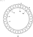
- the friction plate 10 of the illustrated embodiment is comprised of an annular plate 12, and two or more friction material segments 14 are fixed in the circumferential direction on the plate 12.
- the friction material segments 14 are also fixed on the back side of the plate 12 in the same arrangement.
- the oil groove 16 is formed by the adjacent friction material segments 14 passing from the inner circumference side to the perimeter side of the plate 12.
- the plate 12 and the friction material 14 can be made in a conventional manner using a well-known technology.
- a piece of an annular friction material may be bonded on the plate 12 and oil grooves 16 can be formed by means of pressing operation.
- Each oil groove 16 forms a pair of sectors which spread in both directions, namely, toward the side of inner circumference and the perimeter.
- the oil groove 16a formed by the adjacent friction material segments 14 has sectors, namely, the larger, inner one and the smaller outer one.
- the oil groove 16b formed by the adjacent friction material segments 14 has sectors, namely, the larger, outer one and the smaller, inner one.
- the oil groove 16a and the oil groove 16b do not necessarily need to be arranged in the direction of a circumference alternatingly as illustrated.
- oil grooves of other contours may be provided in addition to the oil groove 16a and the oil groove 16b, and the oil groove 16a or oil groove 16b may be repeated in the direction of a circumference by appropriately modifying the shapes of the friction material segments.
- the lubricating oil dragged by the mating plate moves to the perimeter side by a centrifugal force, being dragged in the circumferential direction of the friction plate 10.
- the lubricating oil passing through the oil groove 16a overflows and runs aground on the friction material segment 14 causing a separating force.
- the lubricant which passes through the oil groove 16b may be efficiently discharged toward the perimeter side owing to the configuration of the oil groove 16b spreading outwardly. For this reason, while the lube oil runs aground onto the friction material segments 14 making the content of air increase, the lube oil can be efficiently discharged to the perimeter side of the friction plate 10, thus, remarkably reducing the drag torque.
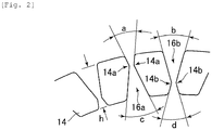
- the sectors of the oil groove 16a formed by the adjacent edges of the friction material segments 14 are characterized by the perimeter side vertexes 14a.
- the sectors of the oil groove 16b formed by the adjacent edges of the friction materials 14 are characterized by the inner circumference side vertexes 14b.
- the vertex located in the perimeter side is the perimeter side vertex 14a
- the vertex located in the inner circumference side is the inner circumference side vertex 14b. It may be necessary that the facing perimeter side vertexes 14a and inner circumference side vertexes 14b should not be in contact with each other.
- a pair of the friction material segments 14 having the facing perimeter side vertexes 14a and the inner circumference side vertexes 14b can be pertinently disposed in the range of 0.5 degree - 3 . 5 degrees about the center of the plate 12. It is because the advantages of the present disclosure cannot fully be demonstrated if the adjacent friction material segments 14 having the perimeter side vertex 14a or the inner circumference side vertex 14b separate too much. In short, the appropriate center angle will depend upon the diameter of the plate 12.
- the location of the perimeter side vertex 14a can be 60%-80% in order that the lube oil can run aground onto the friction material 14 with ease.
- the inner circumference side vertex 14b is located within the limits of 20%-40% of the dimension h, it can make a lube oil discharge smoothly.
- the perimeter side vertex 14a and the inner circumference side vertex 14b need to be formed so that they may face with each other on the adjacent friction material segments 14, but the vertexes do not need to be sharp but may be somewhat roundish.
- the sectorial opening angles a, b, c and d as regards the perimeter side vertex 14a or the inner circumference side vertex 14b can be within the limits of 10 degrees - 30 degrees.
- provision of the perimeter side vertex 14a and the inner circumference side vertex 14b on a pair of the radially extending edges of a friction material segment sandwiched by the adjacent oil grooves 16a and 16b may be desirable, since by so doing, the oil groove 16a and the oil groove 16b can be arranged alternatingly over the whole annular surface of the plate 12.
- oil grooves 16a and 16b need to be formed partly on the friction plate 10, and in the remaining part, oil grooves of other contours (not shown) may be provided.
- the discharging efficiency of a lube oil can be increased, and also the content of air of a lube oil can be caused to increase significantly so that friction plates with less drag torque can be provided.
Landscapes
- Engineering & Computer Science (AREA)
- General Engineering & Computer Science (AREA)
- Mechanical Engineering (AREA)
- Mechanical Operated Clutches (AREA)
- Braking Arrangements (AREA)
Applications Claiming Priority (1)
| Application Number | Priority Date | Filing Date | Title |
|---|---|---|---|
| JP2016110179A JP6752058B2 (ja) | 2016-06-01 | 2016-06-01 | 摩擦板 |
Publications (3)
| Publication Number | Publication Date |
|---|---|
| EP3252331A2 true EP3252331A2 (de) | 2017-12-06 |
| EP3252331A3 EP3252331A3 (de) | 2018-01-31 |
| EP3252331B1 EP3252331B1 (de) | 2020-07-29 |
Family
ID=58778893
Family Applications (1)
| Application Number | Title | Priority Date | Filing Date |
|---|---|---|---|
| EP17172403.2A Active EP3252331B1 (de) | 2016-06-01 | 2017-05-23 | Reibungsplatte |
Country Status (5)
| Country | Link |
|---|---|
| US (1) | US10731712B2 (de) |
| EP (1) | EP3252331B1 (de) |
| JP (1) | JP6752058B2 (de) |
| KR (1) | KR102389805B1 (de) |
| CN (1) | CN107448496B (de) |
Cited By (1)
| Publication number | Priority date | Publication date | Assignee | Title |
|---|---|---|---|---|
| CN112324814A (zh) * | 2020-10-22 | 2021-02-05 | 博格华纳汽车零部件(宁波)有限公司 | 一种具有新型摩擦材料槽型的湿式摩擦片 |
Families Citing this family (5)
| Publication number | Priority date | Publication date | Assignee | Title |
|---|---|---|---|---|
| JP6254654B1 (ja) * | 2016-09-08 | 2017-12-27 | アイシン化工株式会社 | 湿式摩擦材 |
| DE102018003829A1 (de) * | 2018-05-11 | 2019-11-14 | Borgwarner Inc. | Reiblamelle und reibschlüssig arbeitende Einrichtung mit einer solchen Reiblamelle |
| DE102019205571A1 (de) * | 2019-04-17 | 2020-10-22 | Zf Friedrichshafen Ag | Kühlölleitelement sowie Antriebsstrang und Hybridmodul mit diesem |
| DE102019205570A1 (de) * | 2019-04-17 | 2020-10-22 | Zf Friedrichshafen Ag | Kühlölleitelement sowie Antriebsstrang mit diesem |
| CN110259843A (zh) * | 2019-06-20 | 2019-09-20 | 泰州三羊重型机械有限公司 | 一种用于湿式离合器的摩擦片 |
Citations (2)
| Publication number | Priority date | Publication date | Assignee | Title |
|---|---|---|---|---|
| JP2005265186A (ja) | 2004-02-18 | 2005-09-29 | Dainatsukusu:Kk | 湿式摩擦係合要素の摩擦板の溝構造の最適化方法 |
| JP2014169785A (ja) | 2013-02-05 | 2014-09-18 | Nsk Warner Kk | 摩擦板及び摩擦板を備えた湿式多板クラッチ |
Family Cites Families (23)
| Publication number | Priority date | Publication date | Assignee | Title |
|---|---|---|---|---|
| US2690248A (en) * | 1950-10-04 | 1954-09-28 | Gen Motors Corp | Clutch plate with grooves for lubricant or coolant |
| US3493087A (en) * | 1968-07-09 | 1970-02-03 | Eaton Yale & Towne | Hoist load brake |
| JPH01140029U (de) * | 1988-03-18 | 1989-09-25 | ||
| JPH0229331U (de) * | 1988-08-15 | 1990-02-26 | ||
| JP4163283B2 (ja) * | 1998-04-23 | 2008-10-08 | Nskワーナー株式会社 | 摩擦板の製造方法及び装置 |
| JP2003090370A (ja) * | 2001-09-20 | 2003-03-28 | Honda Motor Co Ltd | 湿式多板クラッチ、湿式多板ブレーキ等の湿式フリクションプレート |
| US7234580B2 (en) | 2004-02-18 | 2007-06-26 | Dynax Corporation | Method for optimizing groove structure of friction plate of wet type friction engagement apparatus |
| JP4083695B2 (ja) * | 2004-03-29 | 2008-04-30 | アイシン化工株式会社 | 湿式摩擦材 |
| JP4503416B2 (ja) * | 2004-10-28 | 2010-07-14 | Nskワーナー株式会社 | 湿式摩擦板の製造方法 |
| JP2006132581A (ja) * | 2004-11-02 | 2006-05-25 | Aisin Chem Co Ltd | セグメントタイプ摩擦材 |
| JP2008175354A (ja) * | 2007-01-22 | 2008-07-31 | Aisin Chem Co Ltd | 湿式摩擦材 |
| JP2009047229A (ja) * | 2007-08-20 | 2009-03-05 | Aisin Chem Co Ltd | 湿式摩擦材 |
| JP2009068689A (ja) * | 2007-08-20 | 2009-04-02 | Aisin Chem Co Ltd | 湿式摩擦材 |
| EP2028382B1 (de) * | 2007-08-20 | 2014-04-23 | Aisin Kako Kabushiki Kaisha | Nasses Reibungsmaterial |
| WO2011033861A1 (ja) * | 2009-09-15 | 2011-03-24 | アイシン化工株式会社 | セグメントタイプ摩擦材 |
| CN102822549B (zh) * | 2010-03-25 | 2015-10-14 | 爱信化工株式会社 | 湿式摩擦件 |
| DE102010021900B4 (de) * | 2010-05-28 | 2019-08-14 | Volkswagen Ag | Reibvorrichtung, insbesondere Reiblamelle für eine nasslaufende Reibkupplung |
| JP5776310B2 (ja) * | 2011-04-27 | 2015-09-09 | 株式会社エフ・シー・シー | 湿式摩擦プレート |
| JP2013210040A (ja) * | 2012-03-30 | 2013-10-10 | Aisin Chemical Co Ltd | セグメントタイプ摩擦材 |
| JP5913249B2 (ja) * | 2013-05-21 | 2016-04-27 | アイシン化工株式会社 | 湿式摩擦材 |
| DE102013011677A1 (de) * | 2013-07-11 | 2015-01-15 | Borgwarner Inc. | Reibteil für eine reibschlüssig arbeitende Einrichtung |
| JP6135431B2 (ja) * | 2013-09-30 | 2017-05-31 | アイシン・エィ・ダブリュ株式会社 | 摩擦係合要素 |
| JP6085579B2 (ja) * | 2014-03-27 | 2017-02-22 | アイシン化工株式会社 | 湿式摩擦材 |
-
2016
- 2016-06-01 JP JP2016110179A patent/JP6752058B2/ja active Active
-
2017
- 2017-05-22 CN CN201710365009.6A patent/CN107448496B/zh active Active
- 2017-05-23 EP EP17172403.2A patent/EP3252331B1/de active Active
- 2017-05-24 US US15/603,507 patent/US10731712B2/en active Active
- 2017-05-29 KR KR1020170066115A patent/KR102389805B1/ko active Active
Patent Citations (2)
| Publication number | Priority date | Publication date | Assignee | Title |
|---|---|---|---|---|
| JP2005265186A (ja) | 2004-02-18 | 2005-09-29 | Dainatsukusu:Kk | 湿式摩擦係合要素の摩擦板の溝構造の最適化方法 |
| JP2014169785A (ja) | 2013-02-05 | 2014-09-18 | Nsk Warner Kk | 摩擦板及び摩擦板を備えた湿式多板クラッチ |
Cited By (1)
| Publication number | Priority date | Publication date | Assignee | Title |
|---|---|---|---|---|
| CN112324814A (zh) * | 2020-10-22 | 2021-02-05 | 博格华纳汽车零部件(宁波)有限公司 | 一种具有新型摩擦材料槽型的湿式摩擦片 |
Also Published As
| Publication number | Publication date |
|---|---|
| KR102389805B1 (ko) | 2022-04-21 |
| JP6752058B2 (ja) | 2020-09-09 |
| KR20170136439A (ko) | 2017-12-11 |
| US20170350456A1 (en) | 2017-12-07 |
| CN107448496B (zh) | 2020-06-26 |
| EP3252331A3 (de) | 2018-01-31 |
| US10731712B2 (en) | 2020-08-04 |
| CN107448496A (zh) | 2017-12-08 |
| EP3252331B1 (de) | 2020-07-29 |
| JP2017214999A (ja) | 2017-12-07 |
Similar Documents
| Publication | Publication Date | Title |
|---|---|---|
| EP3252331B1 (de) | Reibungsplatte | |
| US5460255A (en) | Universal segmented friction clutch facing | |
| CN105051391B (zh) | 摩擦片和具备摩擦片的湿式多片离合器 | |
| US4139085A (en) | Dry disc-type clutch | |
| EP0550961B1 (de) | Belagmaterial für Nasslaufkupplungsscheibe | |
| US5101953A (en) | High capacity viscous pumping groove pattern for a wet clutch | |
| JP6709742B2 (ja) | 摩擦板 | |
| US9291211B2 (en) | Wet friction material | |
| US10316901B2 (en) | Clutch plate separation for drag loss reduction | |
| US20180238398A1 (en) | Methods and apparatus for clutch and brake drag reduction using springs | |
| JP2013124747A (ja) | ウェーブ形摩擦板 | |
| JP2003056614A (ja) | 湿式摩擦部材 | |
| US10724581B2 (en) | Friction plate and hydraulic transmission apparatus | |
| JP5670668B2 (ja) | 湿式摩擦板 | |
| CN208535020U (zh) | 抛物线型的油槽摩擦片 | |
| US9121484B2 (en) | Torque converter with impeller clutch | |
| US20210071726A1 (en) | Friction plate and friction engagement device provided with the same | |
| JP6391591B2 (ja) | 担持体リングと横断部材とを備える駆動ベルト | |
| JP5913182B2 (ja) | 湿式摩擦材 | |
| KR101870349B1 (ko) | 드래그토크 저감용 웨이브형 습식클러치 마찰패드 및 이를 구비한 습식 다판 클러치 | |
| KR20160061791A (ko) | 차량용 다판 클러치 장치 | |
| CN108291584A (zh) | 摩擦离合器 | |
| JP2019124280A (ja) | ウェーブ形摩擦板 |
Legal Events
| Date | Code | Title | Description |
|---|---|---|---|
| PUAI | Public reference made under article 153(3) epc to a published international application that has entered the european phase |
Free format text: ORIGINAL CODE: 0009012 |
|
| STAA | Information on the status of an ep patent application or granted ep patent |
Free format text: STATUS: THE APPLICATION HAS BEEN PUBLISHED |
|
| AK | Designated contracting states |
Kind code of ref document: A2 Designated state(s): AL AT BE BG CH CY CZ DE DK EE ES FI FR GB GR HR HU IE IS IT LI LT LU LV MC MK MT NL NO PL PT RO RS SE SI SK SM TR |
|
| AX | Request for extension of the european patent |
Extension state: BA ME |
|
| PUAL | Search report despatched |
Free format text: ORIGINAL CODE: 0009013 |
|
| AK | Designated contracting states |
Kind code of ref document: A3 Designated state(s): AL AT BE BG CH CY CZ DE DK EE ES FI FR GB GR HR HU IE IS IT LI LT LU LV MC MK MT NL NO PL PT RO RS SE SI SK SM TR |
|
| AX | Request for extension of the european patent |
Extension state: BA ME |
|
| RIC1 | Information provided on ipc code assigned before grant |
Ipc: F16D 13/58 20060101ALI20171222BHEP Ipc: F16D 13/72 20060101ALI20171222BHEP Ipc: F16D 25/12 20060101ALI20171222BHEP Ipc: F16D 13/52 20060101AFI20171222BHEP Ipc: F16D 13/64 20060101ALI20171222BHEP Ipc: F16D 13/74 20060101ALI20171222BHEP |
|
| STAA | Information on the status of an ep patent application or granted ep patent |
Free format text: STATUS: REQUEST FOR EXAMINATION WAS MADE |
|
| 17P | Request for examination filed |
Effective date: 20180620 |
|
| RBV | Designated contracting states (corrected) |
Designated state(s): AL AT BE BG CH CY CZ DE DK EE ES FI FR GB GR HR HU IE IS IT LI LT LU LV MC MK MT NL NO PL PT RO RS SE SI SK SM TR |
|
| STAA | Information on the status of an ep patent application or granted ep patent |
Free format text: STATUS: EXAMINATION IS IN PROGRESS |
|
| 17Q | First examination report despatched |
Effective date: 20200225 |
|
| GRAP | Despatch of communication of intention to grant a patent |
Free format text: ORIGINAL CODE: EPIDOSNIGR1 |
|
| STAA | Information on the status of an ep patent application or granted ep patent |
Free format text: STATUS: GRANT OF PATENT IS INTENDED |
|
| INTG | Intention to grant announced |
Effective date: 20200430 |
|
| GRAS | Grant fee paid |
Free format text: ORIGINAL CODE: EPIDOSNIGR3 |
|
| GRAA | (expected) grant |
Free format text: ORIGINAL CODE: 0009210 |
|
| STAA | Information on the status of an ep patent application or granted ep patent |
Free format text: STATUS: THE PATENT HAS BEEN GRANTED |
|
| AK | Designated contracting states |
Kind code of ref document: B1 Designated state(s): AL AT BE BG CH CY CZ DE DK EE ES FI FR GB GR HR HU IE IS IT LI LT LU LV MC MK MT NL NO PL PT RO RS SE SI SK SM TR |
|
| REG | Reference to a national code |
Ref country code: CH Ref legal event code: EP |
|
| REG | Reference to a national code |
Ref country code: AT Ref legal event code: REF Ref document number: 1296154 Country of ref document: AT Kind code of ref document: T Effective date: 20200815 |
|
| REG | Reference to a national code |
Ref country code: IE Ref legal event code: FG4D |
|
| REG | Reference to a national code |
Ref country code: DE Ref legal event code: R096 Ref document number: 602017020419 Country of ref document: DE |
|
| REG | Reference to a national code |
Ref country code: LT Ref legal event code: MG4D |
|
| REG | Reference to a national code |
Ref country code: NL Ref legal event code: MP Effective date: 20200729 |
|
| REG | Reference to a national code |
Ref country code: AT Ref legal event code: MK05 Ref document number: 1296154 Country of ref document: AT Kind code of ref document: T Effective date: 20200729 |
|
| PG25 | Lapsed in a contracting state [announced via postgrant information from national office to epo] |
Ref country code: AT Free format text: LAPSE BECAUSE OF FAILURE TO SUBMIT A TRANSLATION OF THE DESCRIPTION OR TO PAY THE FEE WITHIN THE PRESCRIBED TIME-LIMIT Effective date: 20200729 Ref country code: SE Free format text: LAPSE BECAUSE OF FAILURE TO SUBMIT A TRANSLATION OF THE DESCRIPTION OR TO PAY THE FEE WITHIN THE PRESCRIBED TIME-LIMIT Effective date: 20200729 Ref country code: LT Free format text: LAPSE BECAUSE OF FAILURE TO SUBMIT A TRANSLATION OF THE DESCRIPTION OR TO PAY THE FEE WITHIN THE PRESCRIBED TIME-LIMIT Effective date: 20200729 Ref country code: BG Free format text: LAPSE BECAUSE OF FAILURE TO SUBMIT A TRANSLATION OF THE DESCRIPTION OR TO PAY THE FEE WITHIN THE PRESCRIBED TIME-LIMIT Effective date: 20201029 Ref country code: GR Free format text: LAPSE BECAUSE OF FAILURE TO SUBMIT A TRANSLATION OF THE DESCRIPTION OR TO PAY THE FEE WITHIN THE PRESCRIBED TIME-LIMIT Effective date: 20201030 Ref country code: ES Free format text: LAPSE BECAUSE OF FAILURE TO SUBMIT A TRANSLATION OF THE DESCRIPTION OR TO PAY THE FEE WITHIN THE PRESCRIBED TIME-LIMIT Effective date: 20200729 Ref country code: HR Free format text: LAPSE BECAUSE OF FAILURE TO SUBMIT A TRANSLATION OF THE DESCRIPTION OR TO PAY THE FEE WITHIN THE PRESCRIBED TIME-LIMIT Effective date: 20200729 Ref country code: PT Free format text: LAPSE BECAUSE OF FAILURE TO SUBMIT A TRANSLATION OF THE DESCRIPTION OR TO PAY THE FEE WITHIN THE PRESCRIBED TIME-LIMIT Effective date: 20201130 Ref country code: FI Free format text: LAPSE BECAUSE OF FAILURE TO SUBMIT A TRANSLATION OF THE DESCRIPTION OR TO PAY THE FEE WITHIN THE PRESCRIBED TIME-LIMIT Effective date: 20200729 Ref country code: NO Free format text: LAPSE BECAUSE OF FAILURE TO SUBMIT A TRANSLATION OF THE DESCRIPTION OR TO PAY THE FEE WITHIN THE PRESCRIBED TIME-LIMIT Effective date: 20201029 |
|
| PG25 | Lapsed in a contracting state [announced via postgrant information from national office to epo] |
Ref country code: LV Free format text: LAPSE BECAUSE OF FAILURE TO SUBMIT A TRANSLATION OF THE DESCRIPTION OR TO PAY THE FEE WITHIN THE PRESCRIBED TIME-LIMIT Effective date: 20200729 Ref country code: RS Free format text: LAPSE BECAUSE OF FAILURE TO SUBMIT A TRANSLATION OF THE DESCRIPTION OR TO PAY THE FEE WITHIN THE PRESCRIBED TIME-LIMIT Effective date: 20200729 Ref country code: PL Free format text: LAPSE BECAUSE OF FAILURE TO SUBMIT A TRANSLATION OF THE DESCRIPTION OR TO PAY THE FEE WITHIN THE PRESCRIBED TIME-LIMIT Effective date: 20200729 Ref country code: IS Free format text: LAPSE BECAUSE OF FAILURE TO SUBMIT A TRANSLATION OF THE DESCRIPTION OR TO PAY THE FEE WITHIN THE PRESCRIBED TIME-LIMIT Effective date: 20201129 |
|
| PG25 | Lapsed in a contracting state [announced via postgrant information from national office to epo] |
Ref country code: NL Free format text: LAPSE BECAUSE OF FAILURE TO SUBMIT A TRANSLATION OF THE DESCRIPTION OR TO PAY THE FEE WITHIN THE PRESCRIBED TIME-LIMIT Effective date: 20200729 |
|
| PG25 | Lapsed in a contracting state [announced via postgrant information from national office to epo] |
Ref country code: EE Free format text: LAPSE BECAUSE OF FAILURE TO SUBMIT A TRANSLATION OF THE DESCRIPTION OR TO PAY THE FEE WITHIN THE PRESCRIBED TIME-LIMIT Effective date: 20200729 Ref country code: SM Free format text: LAPSE BECAUSE OF FAILURE TO SUBMIT A TRANSLATION OF THE DESCRIPTION OR TO PAY THE FEE WITHIN THE PRESCRIBED TIME-LIMIT Effective date: 20200729 Ref country code: RO Free format text: LAPSE BECAUSE OF FAILURE TO SUBMIT A TRANSLATION OF THE DESCRIPTION OR TO PAY THE FEE WITHIN THE PRESCRIBED TIME-LIMIT Effective date: 20200729 Ref country code: DK Free format text: LAPSE BECAUSE OF FAILURE TO SUBMIT A TRANSLATION OF THE DESCRIPTION OR TO PAY THE FEE WITHIN THE PRESCRIBED TIME-LIMIT Effective date: 20200729 Ref country code: CZ Free format text: LAPSE BECAUSE OF FAILURE TO SUBMIT A TRANSLATION OF THE DESCRIPTION OR TO PAY THE FEE WITHIN THE PRESCRIBED TIME-LIMIT Effective date: 20200729 |
|
| REG | Reference to a national code |
Ref country code: DE Ref legal event code: R097 Ref document number: 602017020419 Country of ref document: DE |
|
| PG25 | Lapsed in a contracting state [announced via postgrant information from national office to epo] |
Ref country code: AL Free format text: LAPSE BECAUSE OF FAILURE TO SUBMIT A TRANSLATION OF THE DESCRIPTION OR TO PAY THE FEE WITHIN THE PRESCRIBED TIME-LIMIT Effective date: 20200729 |
|
| PLBE | No opposition filed within time limit |
Free format text: ORIGINAL CODE: 0009261 |
|
| STAA | Information on the status of an ep patent application or granted ep patent |
Free format text: STATUS: NO OPPOSITION FILED WITHIN TIME LIMIT |
|
| PG25 | Lapsed in a contracting state [announced via postgrant information from national office to epo] |
Ref country code: SK Free format text: LAPSE BECAUSE OF FAILURE TO SUBMIT A TRANSLATION OF THE DESCRIPTION OR TO PAY THE FEE WITHIN THE PRESCRIBED TIME-LIMIT Effective date: 20200729 |
|
| 26N | No opposition filed |
Effective date: 20210430 |
|
| PG25 | Lapsed in a contracting state [announced via postgrant information from national office to epo] |
Ref country code: SI Free format text: LAPSE BECAUSE OF FAILURE TO SUBMIT A TRANSLATION OF THE DESCRIPTION OR TO PAY THE FEE WITHIN THE PRESCRIBED TIME-LIMIT Effective date: 20200729 |
|
| REG | Reference to a national code |
Ref country code: CH Ref legal event code: PL |
|
| GBPC | Gb: european patent ceased through non-payment of renewal fee |
Effective date: 20210523 |
|
| PG25 | Lapsed in a contracting state [announced via postgrant information from national office to epo] |
Ref country code: CH Free format text: LAPSE BECAUSE OF NON-PAYMENT OF DUE FEES Effective date: 20210531 Ref country code: LI Free format text: LAPSE BECAUSE OF NON-PAYMENT OF DUE FEES Effective date: 20210531 Ref country code: MC Free format text: LAPSE BECAUSE OF FAILURE TO SUBMIT A TRANSLATION OF THE DESCRIPTION OR TO PAY THE FEE WITHIN THE PRESCRIBED TIME-LIMIT Effective date: 20200729 Ref country code: LU Free format text: LAPSE BECAUSE OF NON-PAYMENT OF DUE FEES Effective date: 20210523 |
|
| REG | Reference to a national code |
Ref country code: BE Ref legal event code: MM Effective date: 20210531 |
|
| PG25 | Lapsed in a contracting state [announced via postgrant information from national office to epo] |
Ref country code: IE Free format text: LAPSE BECAUSE OF NON-PAYMENT OF DUE FEES Effective date: 20210523 Ref country code: GB Free format text: LAPSE BECAUSE OF NON-PAYMENT OF DUE FEES Effective date: 20210523 |
|
| PG25 | Lapsed in a contracting state [announced via postgrant information from national office to epo] |
Ref country code: BE Free format text: LAPSE BECAUSE OF NON-PAYMENT OF DUE FEES Effective date: 20210531 |
|
| PG25 | Lapsed in a contracting state [announced via postgrant information from national office to epo] |
Ref country code: HU Free format text: LAPSE BECAUSE OF FAILURE TO SUBMIT A TRANSLATION OF THE DESCRIPTION OR TO PAY THE FEE WITHIN THE PRESCRIBED TIME-LIMIT; INVALID AB INITIO Effective date: 20170523 |
|
| PG25 | Lapsed in a contracting state [announced via postgrant information from national office to epo] |
Ref country code: CY Free format text: LAPSE BECAUSE OF FAILURE TO SUBMIT A TRANSLATION OF THE DESCRIPTION OR TO PAY THE FEE WITHIN THE PRESCRIBED TIME-LIMIT Effective date: 20200729 |
|
| P01 | Opt-out of the competence of the unified patent court (upc) registered |
Effective date: 20230526 |
|
| PG25 | Lapsed in a contracting state [announced via postgrant information from national office to epo] |
Ref country code: MK Free format text: LAPSE BECAUSE OF FAILURE TO SUBMIT A TRANSLATION OF THE DESCRIPTION OR TO PAY THE FEE WITHIN THE PRESCRIBED TIME-LIMIT Effective date: 20200729 |
|
| PG25 | Lapsed in a contracting state [announced via postgrant information from national office to epo] |
Ref country code: MT Free format text: LAPSE BECAUSE OF FAILURE TO SUBMIT A TRANSLATION OF THE DESCRIPTION OR TO PAY THE FEE WITHIN THE PRESCRIBED TIME-LIMIT Effective date: 20200729 |
|
| PGFP | Annual fee paid to national office [announced via postgrant information from national office to epo] |
Ref country code: DE Payment date: 20250422 Year of fee payment: 9 |
|
| PGFP | Annual fee paid to national office [announced via postgrant information from national office to epo] |
Ref country code: IT Payment date: 20250424 Year of fee payment: 9 |
|
| PGFP | Annual fee paid to national office [announced via postgrant information from national office to epo] |
Ref country code: FR Payment date: 20250528 Year of fee payment: 9 |
|
| PG25 | Lapsed in a contracting state [announced via postgrant information from national office to epo] |
Ref country code: TR Free format text: LAPSE BECAUSE OF FAILURE TO SUBMIT A TRANSLATION OF THE DESCRIPTION OR TO PAY THE FEE WITHIN THE PRESCRIBED TIME-LIMIT Effective date: 20200729 |