EP3252385A1 - Climatiseur - Google Patents
Climatiseur Download PDFInfo
- Publication number
- EP3252385A1 EP3252385A1 EP15879968.4A EP15879968A EP3252385A1 EP 3252385 A1 EP3252385 A1 EP 3252385A1 EP 15879968 A EP15879968 A EP 15879968A EP 3252385 A1 EP3252385 A1 EP 3252385A1
- Authority
- EP
- European Patent Office
- Prior art keywords
- air
- duct
- motor
- ducts
- conditioning apparatus
- Prior art date
- Legal status (The legal status is an assumption and is not a legal conclusion. Google has not performed a legal analysis and makes no representation as to the accuracy of the status listed.)
- Granted
Links
Images
Classifications
-
- F—MECHANICAL ENGINEERING; LIGHTING; HEATING; WEAPONS; BLASTING
- F24—HEATING; RANGES; VENTILATING
- F24F—AIR-CONDITIONING; AIR-HUMIDIFICATION; VENTILATION; USE OF AIR CURRENTS FOR SCREENING
- F24F1/00—Room units for air-conditioning, e.g. separate or self-contained units or units receiving primary air from a central station
- F24F1/0007—Indoor units, e.g. fan coil units
- F24F1/0018—Indoor units, e.g. fan coil units characterised by fans
- F24F1/0033—Indoor units, e.g. fan coil units characterised by fans having two or more fans
-
- F—MECHANICAL ENGINEERING; LIGHTING; HEATING; WEAPONS; BLASTING
- F24—HEATING; RANGES; VENTILATING
- F24F—AIR-CONDITIONING; AIR-HUMIDIFICATION; VENTILATION; USE OF AIR CURRENTS FOR SCREENING
- F24F1/00—Room units for air-conditioning, e.g. separate or self-contained units or units receiving primary air from a central station
- F24F1/0007—Indoor units, e.g. fan coil units
- F24F1/0018—Indoor units, e.g. fan coil units characterised by fans
- F24F1/0022—Centrifugal or radial fans
-
- F—MECHANICAL ENGINEERING; LIGHTING; HEATING; WEAPONS; BLASTING
- F24—HEATING; RANGES; VENTILATING
- F24F—AIR-CONDITIONING; AIR-HUMIDIFICATION; VENTILATION; USE OF AIR CURRENTS FOR SCREENING
- F24F13/00—Details common to, or for air-conditioning, air-humidification, ventilation or use of air currents for screening
- F24F13/32—Supports for air-conditioning, air-humidification or ventilation units
Definitions
- the present invention relates to an air-conditioning apparatus.
- a known air-conditioning apparatus is downsized by forming two air passages oriented in the same direction (for example, Patent Literatures 1 and 2).
- the present invention has been made to solve the above-mentioned problem, and has an object to provide an air-conditioning apparatus capable of reducing a pressure loss in the air passages and configured downsized.
- an air-conditioning apparatus including a casing, a heat exchanger arranged in the casing and configured to exchange heat with air sucked into the casing, a plurality of ducts arranged in the casing in parallel to one another and configured to blow the air subjected to heat exchange in the heat exchanger to an indoor space, a plurality of motors each including a rotary shaft and a main body portion configured to fix one end of the rotary shaft, each of the rotary shafts being arranged to be oriented alternately opposite to one another in a direction perpendicular to a longitudinal direction of the plurality of ducts, the main body portions being arrayed between the plurality of ducts in parallel to the longitudinal direction of the plurality of ducts, a plurality of centrifugal fans each arranged in a corresponding one of the plurality of ducts, and each driven by the plurality of motors, and a partition member including a plurality of motor support portions extending between the plurality of ducts
- the air passages which communicate with the plurality of ducts, do not interfere with each other and do not block the airflow, reducing the pressure loss in the air passages.
- the main body portion of the motor is arranged between the plurality of ducts, downsizing the air-conditioning apparatus.
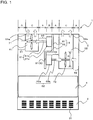
- Fig. 1 is a schematic sectional view for illustrating an example of the air-conditioning apparatus 1 according to Embodiment 1.
- a dimensional relationship and shapes of components are different from the actual dimensional relationship and shapes of the components.
- the same or similar members or portions are denoted by the same reference signs, or reference signs are omitted.
- the air-conditioning apparatus 1 is of a vertical installation type, and is configured to suck indoor air from a lower part of the air-conditioning apparatus 1 and to blow the air subjected to heat exchange from an upper side of the air-conditioning apparatus 1.
- the air-conditioning apparatus 1 of Fig. 1 includes a casing 2, a suction grille 3, a heat exchanger 4, a first duct 51, a second duct 52, a first motor 61, a second motor 62, a first centrifugal fan 71, a second centrifugal fan 72, and a partition member 8.
- the casing 2 is a hollow box body, which may be, for example, formed of a zinc-plated steel sheet.
- the suction grille 3 is arranged on at least one surface of the casing 2 to suck the indoor air into the casing 2.
- the suction grille 3 has, for example, a plurality of rectangular inlet ports 31.
- the suction grille 3 may be formed integrally with the casing 2, or may be removable from the casing 2. Further, an air filter (not shown) configured to remove dust may be mounted to the suction grille 3.
- the heat exchanger 4 is arranged in the casing 2.
- the heat exchanger 4 is configured to exchange heat with air sucked from the suction grille 3, to thereby adjust humidity or temperature.
- heat is exchanged between water or refrigerant flowing in the heat exchanger 4 and the air.
- the first duct 51 and the second duct 52 are pipes arranged in the casing 2 and are configured to blow the air subjected to heat exchange in the heat exchanger 4 to the indoor space.
- the first duct 51 and the second duct 52 may have a cross section having, for example, a rectangular shape, a circular shape, or an oval shape.
- the first duct 51 and the second duct 52 each have one end fixed to an inner surface of the casing 2.
- outlet ports are formed so that an inside and outside of the casing 2 are communicated with each other.
- first duct 51 and the second duct 52 are arranged at a certain distance from inner side surfaces of the casing 2 that are parallel to the first duct 51 and the second duct 52.
- first duct 51 and the second duct 52 are fixed to an upper portion of the casing 2, and are arranged in parallel to each other in a height direction.
- first air outlets 51 a are formed in a fixed portion of the first duct 51
- second air outlets 52a are formed in a fixed portion of the second duct 52.
- the first duct 51 and the second duct 52 may be, for example, pipes formed of a zinc-plated steel sheet.
- the first motor 61 is arranged so that a rotary shaft 61 b is oriented in a direction perpendicular to a longitudinal direction of the first duct 51, and that a tip portion of the rotary shaft 61 b is positioned in the first duct 51. An end portion of the rotary shaft 61 b is fixed to a main body portion 61 a of the first motor 61.
- the second motor 62 is arranged so that a rotary shaft 62b is oriented in a direction perpendicular to a longitudinal direction of the second duct 52, and that a tip portion of the rotary shaft 62b is positioned in the second duct 52. An end portion of the rotary shaft 62b is fixed to a main body portion 62a of the second motor 62.
- an orientation of the rotary shaft 62b of the second motor 62 is set to be alternately opposite to an orientation of the rotary shaft 61 b of the first motor 61.
- the main body portion 61 a of the first motor 61 and the main body portion 62a of the second motor 62 are arrayed between the first duct 51 and the second duct 52 in parallel to the longitudinal direction of the first duct 51 and the second duct 52.
- the main body portion 61 a of the first motor 61 is arranged above the main body portion 62a of the second motor 62.
- the main body portion 62a of the second motor 62 may be arranged above the main body portion 61 a of the first motor 61.
- the first motor 61 and the second motor 62 may be the motors of the same type, for example, an induction motor or a DC brushless motor.
- the first centrifugal fan 71 and the second centrifugal fan 72 are air-sending devices configured to push out air sucked from a rotary shaft direction to a centrifugal direction.
- the first centrifugal fan 71 is arranged in the first duct 51 and driven by the first motor 61.
- a rotary shaft of the first centrifugal fan 71 is fixed to the tip portion of the rotary shaft 61 b of the first motor 61.
- the second centrifugal fan 72 is arranged in the second duct 52 and driven by the second motor 62.
- a rotary shaft of the second centrifugal fan 72 is fixed to the tip portion of the rotary shaft 62b of the second motor 62.
- the first centrifugal fan 71 is arranged above the second centrifugal fan 72.
- the first centrifugal fan 71 and the second centrifugal fan 72 are arranged at a distance not to overlap with each other in the rotary shaft direction. Further, mounting directions of the first centrifugal fan 71 and the second centrifugal fan 72 are opposite to each other.
- the rotary shaft of the first centrifugal fan 71 and the rotary shaft of the second centrifugal fan 72 are arranged in parallel to each other.
- first centrifugal fan 71 on the air suction sides are fixed to an inner side surface of the first duct 51.
- a suction port (not shown) is further formed at a position opposed to an air suction port of the first centrifugal fan 71.
- One side surface or both side surfaces of the second centrifugal fan 72 on the air suction sides are fixed to an inner side surface of the second duct 52.
- a suction port (not shown) is further formed at a position opposed to an air suction port of the second centrifugal fan 72.
- the first centrifugal fan 71 and the second centrifugal fan 72 may each be a sirocco fan or a turbofan. Further, the first centrifugal fan 71 and the second centrifugal fan 72 may have an equal fan diameter.
- the partition member 8 is arranged between the first duct 51 and the second duct 52.
- the partition member 8 includes flat-plate-shaped motor support portions 81 extending between the first duct 51 and the second duct 52 in parallel to those ducts and one of the motor support portions 81 is configured to fixing the main body portion 61 a of the first motor 61 on a side opposite to the rotary shaft 61 b.
- the main body portion 62a of the second motor 62 is also fixed to the other one of motor support portions 81, which extends between the first duct 51 and the second duct 52 in parallel to those ducts, on a side opposite to the rotary shaft 62b of the second motor 62.
- the partition member 8 further includes a flat-plate-shaped connecting portion 82 configured to connect the plurality of motor support portions 81, which are next to each other.
- the partition member 8 may be a single plate-shaped member alternately having a step.
- the partition member 8 may be formed of the motor support portions 81 and the connecting portion 82 that are prepared as separate plate-shaped members and connected through, for example, brazing. At least one side of the partition member 8 is fixed to an inside of the casing 2 through, for example, brazing.
- the partition member 8 may be formed of, for example, a zinc-plated steel sheet.
- the first duct 51 is arranged at a certain distance from the inner side surface of the casing 2, which is parallel to the first duct 51, so that a part of a space between the first duct 51 and the inner side surface of the casing 2 serves as a first casing-side air passage 91 for sucking the air into the first duct 51.
- the second duct 52 is arranged at a certain distance from the inner side surface of the casing 2, which is parallel to the second duct 52, so that a part of a space between the second duct 52 and the inner side surface of the casing 2 serves as a second casing-side air passage 92 for sucking the air into the second duct 52.
- the air-conditioning apparatus 1 according to Embodiment 1 includes the partition member 8 so that a space having the first duct 51 and a space having the second duct 52 are partitioned to form independent air passages that do not interfere with each other.
- a space between the first duct 51 and the main body portion 61 a of the first motor 61 serves as a first motor-side air passage 93 for sucking the air into the first duct 51.
- a space between the second duct 52 and the main body portion 62a of the second motor 62 serves as a second motor-side air passage 94 for sucking the air into the second duct 52.
- FIG. 1 the airflow in the first duct 51 and the second duct 52 is indicated by the outlined arrows.
- the indoor air is sucked into the casing 2 through the suction grille 3.
- the sucked air is subjected to heat exchange in the heat exchanger 4, and divided into a direction of the first duct 51 and a direction of the second duct 52 by the partition member 8.
- the air divided into the direction of the first duct 51 flows into the first casing-side air passage 91 and the first motor-side air passage 93 to be sucked into the first duct 51 through the suction ports (not shown) of the first duct 51 by the first centrifugal fan 71.
- the air sucked into the first duct 51 is pushed out in the centrifugal direction by the first centrifugal fan 71, and is blown to the indoor space through the first air outlets 51 a. Further, the air divided into the direction of the second duct 52 flows into the second casing-side air passage 92 and the second motor-side air passage 94 to be sucked into the second duct 52 through the suction ports (not shown) of the second duct 52 by the second centrifugal fan 72. The air sucked into the second duct 52 is pushed out in the centrifugal direction by the second centrifugal fan 72, and is blown out to the indoor space through the second air outlets 52a.
- the main body portion 61 a of the first motor 61 and the main body portion 62a of the second motor 62 are arrayed between the first duct 51 and the second duct 52 in parallel to the longitudinal direction of the first duct 51 and the second duct 52.
- the rotary shaft 61 b of the first motor 61 and the rotary shaft 62b of the second motor 62 are arranged to extend in a direction perpendicular to the first duct 51 and the second duct 52 and to be oriented alternately opposite to one another.
- the partition member 8 extends between the first duct 51 and the second duct 52 in parallel to those ducts.
- the partition member 8 includes the plurality of motor support portions 81 configured to fix the main body portion 61 a of the first motor 61 and the main body portion 62a of the second motor 62 on the sides opposite to the rotary shafts 61 b and 62b, respectively, and the connecting portion 82 configured to connect the plurality of motor support portions 81, which are next to each other.
- two motor support portions 81 and one connecting portion 82 are provided.
- the space having the first duct 51 and the space having the second duct 52 are partitioned by the partition member 8 configured to fix the main body portion 61 a of the first motor 61 and the main body portion 62a of the second motor 62.
- Those spaces serve as the independent air passages, which do not interfere with each other, with the result that the pressure loss in the air passages can be reduced. Consequently, according to Embodiment 1, efficiency of the first centrifugal fan 71 and the second centrifugal fan 72 can be enhanced, eliminating or reducing power consumption of the first motor 61 and the second motor 62. As a result, energy consumption of the first motor 61 and the second motor 62 can be reduced, enabling a long-time use of the first motor 61 and the second motor 62.
- the air-conditioning apparatus 1 can be downsized. Description below is made of the downsizing with reference to Fig. 1 and Fig. 2 .
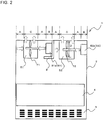
- the outlined arrows of Fig. 2 indicate the airflow.
- Fig. 2 is a schematic sectional view for illustrating an example of a related-art air-conditioning apparatus 1.
- the first motor 61 and the second motor 62 are arranged at the same level in the height direction and are arranged in parallel to each other in a horizontal direction with an orientation in the same direction. That is, unlike the air-conditioning apparatus 1 of Embodiment 1, the first motor 61 and the second motor 62 of Fig. 2 are not arranged between the first duct 51 and the second duct 52 in parallel to the longitudinal direction of the first duct 51 and the second duct 52. Further, the first centrifugal fan 71 and the second centrifugal fan 72 are arranged at the same level in the height direction and are arranged in parallel to each other in the horizontal direction. Moreover, the first motor 61 is fixed to an L-shaped partition member 8 arranged between the first duct 51 and the second duct 52, and the second motor 62 is fixed to the inner side surface of the casing 2.
- the first casing-side air passage 91, the second casing-side air passage 92, the first motor-side air passage 93, and the second motor-side air passage 94 have an equal minimum width A.
- the first motor 61 and the second motor 62 are of the same type, and the main body portion 61 a of the first motor 61 and the main body portion 62a of the second motor 62 have an equal motor width B in the rotary shaft direction.
- the first duct 51 and the second duct 52 have an equal cross-sectional width C.
- the first centrifugal fan 71 and the second centrifugal fan 72 have an equal fan diameter D.
- the first casing-side air passage 91, the second casing-side air passage 92, the first motor-side air passage 93, and the second motor-side air passage 94 are required to be formed so that the minimum width A is equal to or larger than one-half of the fan diameter D, that is, a relationship of A ⁇ D/2 is satisfied.
- a width of the casing 2 corresponds to 4A + 2B + 2C.
- a width of the casing 2 corresponds to 4A + B + 2C.
- the casing 2 can be downsized by the motor width B.
- the air-conditioning apparatus 1 can be downsized while the air passages, through which the first centrifugal fan 71 and the second centrifugal fan 72 suck the air, are secured.
- manufacturing cost can be reduced.
- the reduction in manufacturing cost can also be achieved by setting an equal fan diameter to the first centrifugal fan 71 and the second centrifugal fan 72.
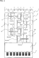
- Fig. 3 is a schematic sectional view for illustrating an example of the air-conditioning apparatus 1 according to Embodiment 2.
- a main body portion 63a of a third motor 63 and a main body portion 64a of a fourth motor 64 are arranged between the first duct 51 and the second duct 52 in parallel to the longitudinal direction of the first duct 51 and the second duct 52.
- a rotary shaft 63b of the third motor 63 and a rotary shaft 64b of the fourth motor 64 are arranged to be oriented alternately opposite to one another in the direction perpendicular to the first duct 51 and the second duct 52.
- a third centrifugal fan 73 driven by the third motor 63 is arranged in the first duct 51.
- a rotary shaft of the third centrifugal fan 73 is fixed to a tip portion of the rotary shaft 63b of the third motor 63.
- One side surface or both side surfaces of the third centrifugal fan 73 on the air suction sides are fixed to the inner side surface of the first duct 51.
- a suction port (not shown) is further formed at a position opposed to an air suction port of the third centrifugal fan 73.
- a suction port (not shown) is further formed at a position opposed to the air suction port of the first centrifugal fan 71.
- a fourth centrifugal fan 74 driven by the fourth motor 64 is arranged in the second duct 52.
- a rotary shaft of the fourth centrifugal fan 74 is fixed to a tip portion of the rotary shaft 64b of the fourth motor 64.
- One side surface or both side surfaces of the fourth centrifugal fan 74 on the air suction sides are fixed to the inner side surface of the second duct 52.
- a suction port (not shown) is further formed at a position opposed to an air suction port of the fourth centrifugal fan 74.
- the main body portion 63a of the third motor 63 is fixed to one of the motor support portions 81, which extends between the first duct 51 and the second duct 52 in parallel to those ducts, on a side opposite to the rotary shaft 63b of the third motor 63.
- the main body portion 64a of the fourth motor 64 is fixed to another one of the motor support portions 81, which extends between the first duct 51 and the second duct 52 in parallel to those ducts, on a side opposite to the rotary shaft 64b of the fourth motor 64.
- the remaining structure of the air-conditioning apparatus 1 is the same as that of Embodiment 1, and the description of the same structure is omitted.
- the air-conditioning apparatus 1 In the air-conditioning apparatus 1 according to Embodiment 2, a plurality of centrifugal fans and motors are arranged. Thus, the performance of the air-conditioning apparatus 1 can be maintained even when the performance of each centrifugal fan and each motor is degraded. Consequently, in the air-conditioning apparatus 1 according to Embodiment 2, the fan diameter D of the centrifugal fan, the motor width B, and the minimum width A of the air passage can be reduced, with the result that the casing 2 can be downsized.
- the present invention is not limited to the above-mentioned Embodiments, and various modifications may be made to the above-mentioned Embodiments.
- the air-conditioning apparatus 1 according to Embodiments described above is an air-conditioning apparatus of a vertical installation type, but the present invention is not limited to this configuration.
- the air-conditioning apparatus 1 of a ceiling embedded type or other type may be adopted.
- the air-conditioning apparatus 1 may be, for example, an air-conditioning apparatus of a fan coil type, an air purifier, a dehumidifier, a humidifier, a cooler, a heater, or a device having a plurality of such functions.
- one motor is configured to drive one centrifugal fan.
- two or more centrifugal fans arranged in the same duct may be driven by a single motor.
- two ducts are arranged in parallel to each other in the height direction.
- three or more ducts may be arranged in parallel to one another in any directions.
- the air outlets are formed on the upper side of the air-conditioning apparatus.
- the position of the air outlets may be changed to any positions corresponding to the type of the air-conditioning apparatus.
Landscapes
- Engineering & Computer Science (AREA)
- Chemical & Material Sciences (AREA)
- Combustion & Propulsion (AREA)
- Mechanical Engineering (AREA)
- General Engineering & Computer Science (AREA)
- Air-Conditioning Room Units, And Self-Contained Units In General (AREA)
- Structures Of Non-Positive Displacement Pumps (AREA)
Applications Claiming Priority (1)
| Application Number | Priority Date | Filing Date | Title |
|---|---|---|---|
| PCT/JP2015/052592 WO2016121071A1 (fr) | 2015-01-29 | 2015-01-29 | Climatiseur |
Publications (3)
| Publication Number | Publication Date |
|---|---|
| EP3252385A1 true EP3252385A1 (fr) | 2017-12-06 |
| EP3252385A4 EP3252385A4 (fr) | 2018-08-29 |
| EP3252385B1 EP3252385B1 (fr) | 2019-11-13 |
Family
ID=56542722
Family Applications (1)
| Application Number | Title | Priority Date | Filing Date |
|---|---|---|---|
| EP15879968.4A Active EP3252385B1 (fr) | 2015-01-29 | 2015-01-29 | Climatiseur |
Country Status (4)
| Country | Link |
|---|---|
| EP (1) | EP3252385B1 (fr) |
| JP (1) | JP6370406B2 (fr) |
| CN (1) | CN206890671U (fr) |
| WO (1) | WO2016121071A1 (fr) |
Families Citing this family (6)
| Publication number | Priority date | Publication date | Assignee | Title |
|---|---|---|---|---|
| US12134058B2 (en) | 2021-05-24 | 2024-11-05 | Lg Electronics Inc. | Filter cleaner and air-processing apparatus including filter cleaner |
| US12480667B2 (en) | 2021-05-24 | 2025-11-25 | Lg Electronics Inc. | Air-conditioning system |
| US12385666B2 (en) | 2021-05-24 | 2025-08-12 | Lg Electronics Inc. | Air-processing apparatus |
| US12326277B2 (en) * | 2021-05-24 | 2025-06-10 | Lg Electronics Inc. | Air-conditioning system |
| US12474068B2 (en) | 2021-05-24 | 2025-11-18 | Lg Electronics Inc. | Air-conditioning system |
| WO2023145010A1 (fr) * | 2022-01-28 | 2023-08-03 | 三菱電機株式会社 | Climatiseur |
Family Cites Families (9)
| Publication number | Priority date | Publication date | Assignee | Title |
|---|---|---|---|---|
| JPS58103626U (ja) * | 1982-01-08 | 1983-07-14 | ダイキン工業株式会社 | 空気調和機 |
| JPS59110824U (ja) * | 1983-01-19 | 1984-07-26 | 三菱重工業株式会社 | 空気調和機 |
| JPS6354505U (fr) * | 1986-09-30 | 1988-04-12 | ||
| JPH044614U (fr) * | 1990-04-27 | 1992-01-16 | ||
| KR20100101019A (ko) * | 2005-05-31 | 2010-09-15 | 엘지전자 주식회사 | 분리형 공기조화기용 실외기 |
| EP2157377B1 (fr) * | 2008-08-21 | 2017-05-03 | Sanyo Electric Co., Ltd. | Appareil de climatisation à l'intérieur avec au moins un ventilateur à courant transversal |
| JP5565664B2 (ja) * | 2009-12-11 | 2014-08-06 | 株式会社富士通ゼネラル | ダクト型空気調和機 |
| JP5832135B2 (ja) * | 2011-05-06 | 2015-12-16 | 三菱重工業株式会社 | 天井埋め込み型空気調和機 |
| ITPD20110342A1 (it) * | 2011-10-31 | 2013-05-01 | Emerson Network Power Srl | Struttura portaventilatori perfezionata per macchine di climatizzazione con passaggio aria sotto pavimento |
-
2015
- 2015-01-29 CN CN201590001161.0U patent/CN206890671U/zh not_active Expired - Lifetime
- 2015-01-29 EP EP15879968.4A patent/EP3252385B1/fr active Active
- 2015-01-29 JP JP2016571612A patent/JP6370406B2/ja not_active Expired - Fee Related
- 2015-01-29 WO PCT/JP2015/052592 patent/WO2016121071A1/fr not_active Ceased
Also Published As
| Publication number | Publication date |
|---|---|
| EP3252385A4 (fr) | 2018-08-29 |
| EP3252385B1 (fr) | 2019-11-13 |
| JP6370406B2 (ja) | 2018-08-08 |
| CN206890671U (zh) | 2018-01-16 |
| WO2016121071A1 (fr) | 2016-08-04 |
| JPWO2016121071A1 (ja) | 2017-07-27 |
Similar Documents
| Publication | Publication Date | Title |
|---|---|---|
| EP3252385B1 (fr) | Climatiseur | |
| JP6248486B2 (ja) | 空気調和機のダクト型室内機 | |
| US20150219348A1 (en) | Air conditioning apparatus | |
| US8408865B2 (en) | Blower | |
| EP3364117B1 (fr) | Unité d'intérieur de climatiseur | |
| EP2827071A1 (fr) | Purge bidirectionnelle, climatiseur intégré au plafond | |
| CN105190187A (zh) | 空调机的室内机和空调机 | |
| CN203964164U (zh) | 空调器 | |
| EP3048375B1 (fr) | Climatiseur | |
| EP3130860B1 (fr) | Climatiseur | |
| JP5743685B2 (ja) | 冷凍空調システム | |
| AU2013100648A4 (en) | Ceiling-embedded duct type indoor unit | |
| CN106321473A (zh) | 用于空调器的贯流风机 | |
| CN1379213A (zh) | 空调机 | |
| US20160298870A1 (en) | Air conditioner and duct configuration thereof | |
| JP2014092333A (ja) | 熱交換換気装置 | |
| JP5472234B2 (ja) | 熱交換型換気装置 | |
| JP2008045780A (ja) | 空気調和装置の室内ユニット | |
| JP7399156B2 (ja) | 空気調和機 | |
| WO2012133392A1 (fr) | Unité source de chaleur | |
| CN114811731A (zh) | 室内机及空调器 | |
| JP5541168B2 (ja) | 熱交換型交換装置 | |
| JP2010216750A (ja) | 空気調和機 | |
| JP2017187242A (ja) | 送風装置 | |
| JP3972788B2 (ja) | 空気調和装置の室内機 |
Legal Events
| Date | Code | Title | Description |
|---|---|---|---|
| STAA | Information on the status of an ep patent application or granted ep patent |
Free format text: STATUS: THE INTERNATIONAL PUBLICATION HAS BEEN MADE |
|
| PUAI | Public reference made under article 153(3) epc to a published international application that has entered the european phase |
Free format text: ORIGINAL CODE: 0009012 |
|
| STAA | Information on the status of an ep patent application or granted ep patent |
Free format text: STATUS: REQUEST FOR EXAMINATION WAS MADE |
|
| 17P | Request for examination filed |
Effective date: 20170615 |
|
| AK | Designated contracting states |
Kind code of ref document: A1 Designated state(s): AL AT BE BG CH CY CZ DE DK EE ES FI FR GB GR HR HU IE IS IT LI LT LU LV MC MK MT NL NO PL PT RO RS SE SI SK SM TR |
|
| AX | Request for extension of the european patent |
Extension state: BA ME |
|
| DAX | Request for extension of the european patent (deleted) | ||
| A4 | Supplementary search report drawn up and despatched |
Effective date: 20180730 |
|
| RIC1 | Information provided on ipc code assigned before grant |
Ipc: F24F 13/32 20060101ALI20180724BHEP Ipc: F24F 1/00 20110101AFI20180724BHEP |
|
| REG | Reference to a national code |
Ref country code: DE Ref legal event code: R079 Ref document number: 602015041833 Country of ref document: DE Free format text: PREVIOUS MAIN CLASS: F24F0001000000 Ipc: F24F0001002200 |
|
| GRAP | Despatch of communication of intention to grant a patent |
Free format text: ORIGINAL CODE: EPIDOSNIGR1 |
|
| STAA | Information on the status of an ep patent application or granted ep patent |
Free format text: STATUS: GRANT OF PATENT IS INTENDED |
|
| RIC1 | Information provided on ipc code assigned before grant |
Ipc: F24F 1/0033 20190101ALI20190509BHEP Ipc: F24F 1/0022 20190101AFI20190509BHEP Ipc: F24F 13/32 20060101ALI20190509BHEP |
|
| INTG | Intention to grant announced |
Effective date: 20190529 |
|
| GRAS | Grant fee paid |
Free format text: ORIGINAL CODE: EPIDOSNIGR3 |
|
| GRAA | (expected) grant |
Free format text: ORIGINAL CODE: 0009210 |
|
| STAA | Information on the status of an ep patent application or granted ep patent |
Free format text: STATUS: THE PATENT HAS BEEN GRANTED |
|
| AK | Designated contracting states |
Kind code of ref document: B1 Designated state(s): AL AT BE BG CH CY CZ DE DK EE ES FI FR GB GR HR HU IE IS IT LI LT LU LV MC MK MT NL NO PL PT RO RS SE SI SK SM TR |
|
| REG | Reference to a national code |
Ref country code: CH Ref legal event code: EP Ref country code: AT Ref legal event code: REF Ref document number: 1202060 Country of ref document: AT Kind code of ref document: T Effective date: 20191115 |
|
| REG | Reference to a national code |
Ref country code: DE Ref legal event code: R096 Ref document number: 602015041833 Country of ref document: DE |
|
| REG | Reference to a national code |
Ref country code: IE Ref legal event code: FG4D |
|
| REG | Reference to a national code |
Ref country code: NL Ref legal event code: MP Effective date: 20191113 |
|
| REG | Reference to a national code |
Ref country code: LT Ref legal event code: MG4D |
|
| PG25 | Lapsed in a contracting state [announced via postgrant information from national office to epo] |
Ref country code: BG Free format text: LAPSE BECAUSE OF FAILURE TO SUBMIT A TRANSLATION OF THE DESCRIPTION OR TO PAY THE FEE WITHIN THE PRESCRIBED TIME-LIMIT Effective date: 20200213 Ref country code: FI Free format text: LAPSE BECAUSE OF FAILURE TO SUBMIT A TRANSLATION OF THE DESCRIPTION OR TO PAY THE FEE WITHIN THE PRESCRIBED TIME-LIMIT Effective date: 20191113 Ref country code: LT Free format text: LAPSE BECAUSE OF FAILURE TO SUBMIT A TRANSLATION OF THE DESCRIPTION OR TO PAY THE FEE WITHIN THE PRESCRIBED TIME-LIMIT Effective date: 20191113 Ref country code: LV Free format text: LAPSE BECAUSE OF FAILURE TO SUBMIT A TRANSLATION OF THE DESCRIPTION OR TO PAY THE FEE WITHIN THE PRESCRIBED TIME-LIMIT Effective date: 20191113 Ref country code: SE Free format text: LAPSE BECAUSE OF FAILURE TO SUBMIT A TRANSLATION OF THE DESCRIPTION OR TO PAY THE FEE WITHIN THE PRESCRIBED TIME-LIMIT Effective date: 20191113 Ref country code: NL Free format text: LAPSE BECAUSE OF FAILURE TO SUBMIT A TRANSLATION OF THE DESCRIPTION OR TO PAY THE FEE WITHIN THE PRESCRIBED TIME-LIMIT Effective date: 20191113 Ref country code: NO Free format text: LAPSE BECAUSE OF FAILURE TO SUBMIT A TRANSLATION OF THE DESCRIPTION OR TO PAY THE FEE WITHIN THE PRESCRIBED TIME-LIMIT Effective date: 20200213 Ref country code: PT Free format text: LAPSE BECAUSE OF FAILURE TO SUBMIT A TRANSLATION OF THE DESCRIPTION OR TO PAY THE FEE WITHIN THE PRESCRIBED TIME-LIMIT Effective date: 20200313 Ref country code: GR Free format text: LAPSE BECAUSE OF FAILURE TO SUBMIT A TRANSLATION OF THE DESCRIPTION OR TO PAY THE FEE WITHIN THE PRESCRIBED TIME-LIMIT Effective date: 20200214 Ref country code: PL Free format text: LAPSE BECAUSE OF FAILURE TO SUBMIT A TRANSLATION OF THE DESCRIPTION OR TO PAY THE FEE WITHIN THE PRESCRIBED TIME-LIMIT Effective date: 20191113 |
|
| PG25 | Lapsed in a contracting state [announced via postgrant information from national office to epo] |
Ref country code: IS Free format text: LAPSE BECAUSE OF FAILURE TO SUBMIT A TRANSLATION OF THE DESCRIPTION OR TO PAY THE FEE WITHIN THE PRESCRIBED TIME-LIMIT Effective date: 20200313 Ref country code: HR Free format text: LAPSE BECAUSE OF FAILURE TO SUBMIT A TRANSLATION OF THE DESCRIPTION OR TO PAY THE FEE WITHIN THE PRESCRIBED TIME-LIMIT Effective date: 20191113 Ref country code: RS Free format text: LAPSE BECAUSE OF FAILURE TO SUBMIT A TRANSLATION OF THE DESCRIPTION OR TO PAY THE FEE WITHIN THE PRESCRIBED TIME-LIMIT Effective date: 20191113 |
|
| PG25 | Lapsed in a contracting state [announced via postgrant information from national office to epo] |
Ref country code: AL Free format text: LAPSE BECAUSE OF FAILURE TO SUBMIT A TRANSLATION OF THE DESCRIPTION OR TO PAY THE FEE WITHIN THE PRESCRIBED TIME-LIMIT Effective date: 20191113 |
|
| PG25 | Lapsed in a contracting state [announced via postgrant information from national office to epo] |
Ref country code: EE Free format text: LAPSE BECAUSE OF FAILURE TO SUBMIT A TRANSLATION OF THE DESCRIPTION OR TO PAY THE FEE WITHIN THE PRESCRIBED TIME-LIMIT Effective date: 20191113 Ref country code: ES Free format text: LAPSE BECAUSE OF FAILURE TO SUBMIT A TRANSLATION OF THE DESCRIPTION OR TO PAY THE FEE WITHIN THE PRESCRIBED TIME-LIMIT Effective date: 20191113 Ref country code: CZ Free format text: LAPSE BECAUSE OF FAILURE TO SUBMIT A TRANSLATION OF THE DESCRIPTION OR TO PAY THE FEE WITHIN THE PRESCRIBED TIME-LIMIT Effective date: 20191113 Ref country code: RO Free format text: LAPSE BECAUSE OF FAILURE TO SUBMIT A TRANSLATION OF THE DESCRIPTION OR TO PAY THE FEE WITHIN THE PRESCRIBED TIME-LIMIT Effective date: 20191113 Ref country code: DK Free format text: LAPSE BECAUSE OF FAILURE TO SUBMIT A TRANSLATION OF THE DESCRIPTION OR TO PAY THE FEE WITHIN THE PRESCRIBED TIME-LIMIT Effective date: 20191113 |
|
| REG | Reference to a national code |
Ref country code: DE Ref legal event code: R097 Ref document number: 602015041833 Country of ref document: DE |
|
| REG | Reference to a national code |
Ref country code: AT Ref legal event code: MK05 Ref document number: 1202060 Country of ref document: AT Kind code of ref document: T Effective date: 20191113 |
|
| PG25 | Lapsed in a contracting state [announced via postgrant information from national office to epo] |
Ref country code: MC Free format text: LAPSE BECAUSE OF FAILURE TO SUBMIT A TRANSLATION OF THE DESCRIPTION OR TO PAY THE FEE WITHIN THE PRESCRIBED TIME-LIMIT Effective date: 20191113 Ref country code: SK Free format text: LAPSE BECAUSE OF FAILURE TO SUBMIT A TRANSLATION OF THE DESCRIPTION OR TO PAY THE FEE WITHIN THE PRESCRIBED TIME-LIMIT Effective date: 20191113 Ref country code: SM Free format text: LAPSE BECAUSE OF FAILURE TO SUBMIT A TRANSLATION OF THE DESCRIPTION OR TO PAY THE FEE WITHIN THE PRESCRIBED TIME-LIMIT Effective date: 20191113 |
|
| REG | Reference to a national code |
Ref country code: CH Ref legal event code: PL |
|
| PLBE | No opposition filed within time limit |
Free format text: ORIGINAL CODE: 0009261 |
|
| STAA | Information on the status of an ep patent application or granted ep patent |
Free format text: STATUS: NO OPPOSITION FILED WITHIN TIME LIMIT |
|
| REG | Reference to a national code |
Ref country code: BE Ref legal event code: MM Effective date: 20200131 |
|
| 26N | No opposition filed |
Effective date: 20200814 |
|
| PG25 | Lapsed in a contracting state [announced via postgrant information from national office to epo] |
Ref country code: LU Free format text: LAPSE BECAUSE OF NON-PAYMENT OF DUE FEES Effective date: 20200129 Ref country code: FR Free format text: LAPSE BECAUSE OF NON-PAYMENT OF DUE FEES Effective date: 20200131 |
|
| PG25 | Lapsed in a contracting state [announced via postgrant information from national office to epo] |
Ref country code: SI Free format text: LAPSE BECAUSE OF FAILURE TO SUBMIT A TRANSLATION OF THE DESCRIPTION OR TO PAY THE FEE WITHIN THE PRESCRIBED TIME-LIMIT Effective date: 20191113 Ref country code: AT Free format text: LAPSE BECAUSE OF FAILURE TO SUBMIT A TRANSLATION OF THE DESCRIPTION OR TO PAY THE FEE WITHIN THE PRESCRIBED TIME-LIMIT Effective date: 20191113 Ref country code: BE Free format text: LAPSE BECAUSE OF NON-PAYMENT OF DUE FEES Effective date: 20200131 Ref country code: LI Free format text: LAPSE BECAUSE OF NON-PAYMENT OF DUE FEES Effective date: 20200131 Ref country code: CH Free format text: LAPSE BECAUSE OF NON-PAYMENT OF DUE FEES Effective date: 20200131 |
|
| PG25 | Lapsed in a contracting state [announced via postgrant information from national office to epo] |
Ref country code: IE Free format text: LAPSE BECAUSE OF NON-PAYMENT OF DUE FEES Effective date: 20200129 Ref country code: IT Free format text: LAPSE BECAUSE OF FAILURE TO SUBMIT A TRANSLATION OF THE DESCRIPTION OR TO PAY THE FEE WITHIN THE PRESCRIBED TIME-LIMIT Effective date: 20191113 |
|
| PG25 | Lapsed in a contracting state [announced via postgrant information from national office to epo] |
Ref country code: TR Free format text: LAPSE BECAUSE OF FAILURE TO SUBMIT A TRANSLATION OF THE DESCRIPTION OR TO PAY THE FEE WITHIN THE PRESCRIBED TIME-LIMIT Effective date: 20191113 Ref country code: MT Free format text: LAPSE BECAUSE OF FAILURE TO SUBMIT A TRANSLATION OF THE DESCRIPTION OR TO PAY THE FEE WITHIN THE PRESCRIBED TIME-LIMIT Effective date: 20191113 Ref country code: CY Free format text: LAPSE BECAUSE OF FAILURE TO SUBMIT A TRANSLATION OF THE DESCRIPTION OR TO PAY THE FEE WITHIN THE PRESCRIBED TIME-LIMIT Effective date: 20191113 |
|
| PG25 | Lapsed in a contracting state [announced via postgrant information from national office to epo] |
Ref country code: MK Free format text: LAPSE BECAUSE OF FAILURE TO SUBMIT A TRANSLATION OF THE DESCRIPTION OR TO PAY THE FEE WITHIN THE PRESCRIBED TIME-LIMIT Effective date: 20191113 |
|
| REG | Reference to a national code |
Ref country code: DE Ref legal event code: R084 Ref document number: 602015041833 Country of ref document: DE |
|
| REG | Reference to a national code |
Ref country code: GB Ref legal event code: 746 Effective date: 20221229 |
|
| P01 | Opt-out of the competence of the unified patent court (upc) registered |
Effective date: 20230512 |
|
| PGFP | Annual fee paid to national office [announced via postgrant information from national office to epo] |
Ref country code: GB Payment date: 20231207 Year of fee payment: 10 |
|
| PGFP | Annual fee paid to national office [announced via postgrant information from national office to epo] |
Ref country code: DE Payment date: 20231205 Year of fee payment: 10 |
|
| REG | Reference to a national code |
Ref country code: DE Ref legal event code: R119 Ref document number: 602015041833 Country of ref document: DE |
|
| GBPC | Gb: european patent ceased through non-payment of renewal fee |
Effective date: 20250129 |
|
| PG25 | Lapsed in a contracting state [announced via postgrant information from national office to epo] |
Ref country code: DE Free format text: LAPSE BECAUSE OF NON-PAYMENT OF DUE FEES Effective date: 20250801 |
|
| PG25 | Lapsed in a contracting state [announced via postgrant information from national office to epo] |
Ref country code: GB Free format text: LAPSE BECAUSE OF NON-PAYMENT OF DUE FEES Effective date: 20250129 |