EP3252400A1 - Dispositif à cycle de réfrigération - Google Patents
Dispositif à cycle de réfrigération Download PDFInfo
- Publication number
- EP3252400A1 EP3252400A1 EP15880000.3A EP15880000A EP3252400A1 EP 3252400 A1 EP3252400 A1 EP 3252400A1 EP 15880000 A EP15880000 A EP 15880000A EP 3252400 A1 EP3252400 A1 EP 3252400A1
- Authority
- EP
- European Patent Office
- Prior art keywords
- heat exchanger
- heat transfer
- refrigeration cycle
- temperature
- windward
- Prior art date
- Legal status (The legal status is an assumption and is not a legal conclusion. Google has not performed a legal analysis and makes no representation as to the accuracy of the status listed.)
- Withdrawn
Links
Images




Classifications
-
- F—MECHANICAL ENGINEERING; LIGHTING; HEATING; WEAPONS; BLASTING
- F25—REFRIGERATION OR COOLING; COMBINED HEATING AND REFRIGERATION SYSTEMS; HEAT PUMP SYSTEMS; MANUFACTURE OR STORAGE OF ICE; LIQUEFACTION SOLIDIFICATION OF GASES
- F25B—REFRIGERATION MACHINES, PLANTS OR SYSTEMS; COMBINED HEATING AND REFRIGERATION SYSTEMS; HEAT PUMP SYSTEMS
- F25B13/00—Compression machines, plants or systems, with reversible cycle
-
- F—MECHANICAL ENGINEERING; LIGHTING; HEATING; WEAPONS; BLASTING
- F28—HEAT EXCHANGE IN GENERAL
- F28D—HEAT-EXCHANGE APPARATUS, NOT PROVIDED FOR IN ANOTHER SUBCLASS, IN WHICH THE HEAT-EXCHANGE MEDIA DO NOT COME INTO DIRECT CONTACT
- F28D1/00—Heat-exchange apparatus having stationary conduit assemblies for one heat-exchange medium only, the media being in contact with different sides of the conduit wall, in which the other heat-exchange medium is a large body of fluid, e.g. domestic or motor car radiators
- F28D1/02—Heat-exchange apparatus having stationary conduit assemblies for one heat-exchange medium only, the media being in contact with different sides of the conduit wall, in which the other heat-exchange medium is a large body of fluid, e.g. domestic or motor car radiators with heat-exchange conduits immersed in the body of fluid
- F28D1/04—Heat-exchange apparatus having stationary conduit assemblies for one heat-exchange medium only, the media being in contact with different sides of the conduit wall, in which the other heat-exchange medium is a large body of fluid, e.g. domestic or motor car radiators with heat-exchange conduits immersed in the body of fluid with tubular conduits
- F28D1/053—Heat-exchange apparatus having stationary conduit assemblies for one heat-exchange medium only, the media being in contact with different sides of the conduit wall, in which the other heat-exchange medium is a large body of fluid, e.g. domestic or motor car radiators with heat-exchange conduits immersed in the body of fluid with tubular conduits the conduits being straight
-
- F—MECHANICAL ENGINEERING; LIGHTING; HEATING; WEAPONS; BLASTING
- F28—HEAT EXCHANGE IN GENERAL
- F28F—DETAILS OF HEAT-EXCHANGE AND HEAT-TRANSFER APPARATUS, OF GENERAL APPLICATION
- F28F27/00—Control arrangements or safety devices specially adapted for heat-exchange or heat-transfer apparatus
-
- F—MECHANICAL ENGINEERING; LIGHTING; HEATING; WEAPONS; BLASTING
- F28—HEAT EXCHANGE IN GENERAL
- F28F—DETAILS OF HEAT-EXCHANGE AND HEAT-TRANSFER APPARATUS, OF GENERAL APPLICATION
- F28F9/00—Casings; Header boxes; Auxiliary supports for elements; Auxiliary members within casings
- F28F9/02—Header boxes; End plates
-
- F—MECHANICAL ENGINEERING; LIGHTING; HEATING; WEAPONS; BLASTING
- F25—REFRIGERATION OR COOLING; COMBINED HEATING AND REFRIGERATION SYSTEMS; HEAT PUMP SYSTEMS; MANUFACTURE OR STORAGE OF ICE; LIQUEFACTION SOLIDIFICATION OF GASES
- F25B—REFRIGERATION MACHINES, PLANTS OR SYSTEMS; COMBINED HEATING AND REFRIGERATION SYSTEMS; HEAT PUMP SYSTEMS
- F25B2313/00—Compression machines, plants or systems with reversible cycle not otherwise provided for
- F25B2313/025—Compression machines, plants or systems with reversible cycle not otherwise provided for using multiple outdoor units
- F25B2313/0253—Compression machines, plants or systems with reversible cycle not otherwise provided for using multiple outdoor units in parallel arrangements
-
- F—MECHANICAL ENGINEERING; LIGHTING; HEATING; WEAPONS; BLASTING
- F25—REFRIGERATION OR COOLING; COMBINED HEATING AND REFRIGERATION SYSTEMS; HEAT PUMP SYSTEMS; MANUFACTURE OR STORAGE OF ICE; LIQUEFACTION SOLIDIFICATION OF GASES
- F25B—REFRIGERATION MACHINES, PLANTS OR SYSTEMS; COMBINED HEATING AND REFRIGERATION SYSTEMS; HEAT PUMP SYSTEMS
- F25B2313/00—Compression machines, plants or systems with reversible cycle not otherwise provided for
- F25B2313/027—Compression machines, plants or systems with reversible cycle not otherwise provided for characterised by the reversing means
- F25B2313/02741—Compression machines, plants or systems with reversible cycle not otherwise provided for characterised by the reversing means using one four-way valve
-
- F—MECHANICAL ENGINEERING; LIGHTING; HEATING; WEAPONS; BLASTING
- F25—REFRIGERATION OR COOLING; COMBINED HEATING AND REFRIGERATION SYSTEMS; HEAT PUMP SYSTEMS; MANUFACTURE OR STORAGE OF ICE; LIQUEFACTION SOLIDIFICATION OF GASES
- F25B—REFRIGERATION MACHINES, PLANTS OR SYSTEMS; COMBINED HEATING AND REFRIGERATION SYSTEMS; HEAT PUMP SYSTEMS
- F25B2313/00—Compression machines, plants or systems with reversible cycle not otherwise provided for
- F25B2313/031—Sensor arrangements
- F25B2313/0315—Temperature sensors near the outdoor heat exchanger
-
- F—MECHANICAL ENGINEERING; LIGHTING; HEATING; WEAPONS; BLASTING
- F25—REFRIGERATION OR COOLING; COMBINED HEATING AND REFRIGERATION SYSTEMS; HEAT PUMP SYSTEMS; MANUFACTURE OR STORAGE OF ICE; LIQUEFACTION SOLIDIFICATION OF GASES
- F25B—REFRIGERATION MACHINES, PLANTS OR SYSTEMS; COMBINED HEATING AND REFRIGERATION SYSTEMS; HEAT PUMP SYSTEMS
- F25B2700/00—Sensing or detecting of parameters; Sensors therefor
- F25B2700/11—Sensor to detect if defrost is necessary
Definitions
- This invention relates to a refrigeration cycle device.
- a heat exchanger having a circular heat transfer pipe is available as a heat exchanger forming a refrigeration cycle device. To improve the performance of the heat exchanger, however, it is necessary to reduce the diameter of the heat transfer pipe, and in recent years, a heat exchanger in which a flat perforated pipe is used as the heat transfer pipe has become available.
- a flow passage sectional area of the small diameter circular pipe or the flat perforated pipe is smaller than the flow passage sectional area of a normal circular pipe. Therefore, when a heat exchanger is formed from an equal number of passes to a heat exchanger in which a normal circular pipe is used as the heat transfer pipe, pressure loss in the heat transfer pipe increases, leading to a reduction in the operating efficiency of the refrigeration cycle.
- the pressure loss can be reduced by increasing the number of passes in the heat exchanger or reducing the length of a single pass of the heat transfer pipe. In the latter case, however, with a multi-row heat exchanger, refrigerant flowing through the heat exchanger cannot be caused to flow in an opposite direction to the air, and as a result, the efficiency of the heat exchanger decreases . Furthermore, a difference occurs between heat exchange amounts in a windward side row and a leeward side row, and therefore frost forms more easily on the windward side row, particularly when the outside air is at a low temperature. When frost adheres to an outdoor heat exchanger, the frost must be melted by implementing a defrosting operation periodically.
- Japanese Patent Application Publication No. 2008-224135 discloses a technique in which an amount of frost adhered to an outdoor heat exchanger is determined from a temperature difference between an outdoor unit refrigerant temperature detected by refrigerant temperature detecting means of an outdoor unit and an outside air temperature detected by outside air temperature detecting means, and when the amount of adhered frost is determined to be small, a defrosting prohibition time is set to be long.
- frost forms unevenly on a heat exchanger in which a distributed thermal load exists due to poor distribution of the refrigerant, and in locations where a large amount of frost is formed, not all of the frost melts.
- frost remains, a performance reduction may occur during a heating operation implemented after the defrosting operation.
- This invention has been designed in consideration of the circumstances described above, and an object thereof is to provide a refrigeration cycle device with which an amount of remaining frost can be reduced in a multi-row heat exchanger having a distributed thermal load.
- a refrigeration cycle device includes a circuit having a compressor, an outdoor heat exchanger, an expansion unit, and an indoor heat exchanger, the outdoor heat exchanger including a fan, a first heat exchanger, and a second heat exchanger disposed downwind of the first heat exchanger relative to an air flow generated by the fan, the first heat exchanger including a first heat transfer pipe and a plurality of first fins intersecting the first heat transfer pipe, the second heat exchanger including a second heat transfer pipe, the first heat transfer pipe being connected to a first header, the second heat transfer pipe being connected to a second header, and the first header and the second header being connected to a branch portion of a manifold via a branch pipe, wherein a first temperature sensor is disposed between the plurality of first fins and the branch portion of the manifold.
- an amount of remaining frost can be reduced in a multi-row heat exchanger having a distributed thermal load.
- FIG. 1 is a view showing a configuration of a refrigeration cycle device according to a first embodiment.
- a refrigeration cycle device 1 includes a circuit 3 through which refrigerant circulates.
- the circuit 3 includes at least a compressor 5, an outdoor heat exchanger 100, an expansion unit 7, and an indoor heat exchanger 9.
- the refrigeration cycle device 1 is capable of performing both a heating operation and a cooling operation (a defrosting operation), and the circuit 3 is provided with a four-way valve 11 for switching between these operations. Further, in Figs. 1 , 3 , 6 , and 7 , a flow of the refrigerant during the cooling operation (the defrosting operation) is indicated by solid line arrows, and a flow of the refrigerant during the heating operation is indicated by dotted line arrows.
- an outlet of the compressor 5 is connected to an inlet of the outdoor heat exchanger 100 via the four-way valve 11.
- An outlet of the outdoor heat exchanger 100 is connected to an inlet of the expansion unit 7.
- the expansion unit 7 is constituted by an expansion valve, for example.
- An outlet of the expansion unit 7 is connected to an inlet of the indoor heat exchanger 9.
- An outlet of the indoor heat exchanger 9 is connected to an inlet of the compressor 5 via the four-way valve 11.
- a control unit 140 is connected to the four-way valve 11 in order to switch a flow passage of the four-way valve 11, or in other words switch between the heating operation and the cooling operation (the defrosting operation), as will be described below. Further, the control unit 140 is connected to the compressor 5 in order to control the operation of the compressor 5 appropriately during the heating operation, the cooling operation, and the defrosting operation.
- an arrow W in the drawing denotes a flow of a fluid that exchanges heat with the refrigerant.
- the arrow W denotes a flow of air that exchanges heat with the refrigerant.
- a fan 9a is provided on a windward side of the indoor heat exchanger 9. A flow of air traveling toward the indoor heat exchanger 9 is actively generated by the fan 9a.
- the indoor heat exchanger 9 and the fan 9a are housed in a case of an indoor unit 15, and the indoor unit 15 is disposed in an indoor space.
- Fig. 2 is a perspective view of the outdoor heat exchanger
- Fig. 3 is a plan view illustrating a configuration of the outdoor heat exchanger. Note that in order to prioritize clarity in the drawings, fins to be described below are not shown in Fig. 2 , and heat transfer pipes to be described below are not shown in Fig. 3 .
- the outdoor heat exchanger 100 includes a fan 100a, a windward row 101 constituting a first heat exchanger, and a leeward row 102 constituting a second heat exchanger.
- the leeward row 102 is disposed downwind of the windward row 101 relative to an air flow generated by the fan 100a.
- the fan 100a is disposed on the windward side of the windward row 101 and the leeward row 102, and the windward row 101 is disposed on the windward side of the leeward row 102.
- a flow of air traveling toward the windward row 101 and the leeward row 102 is actively generated by the fan 100a.
- the outdoor heat exchanger 100 (the windward row 101, the leeward row 102, and the fan 100a), the compressor 5, the expansion unit 7, the four-way valve 11, and the control unit 140 are housed in a case of an outdoor unit 17.
- the windward row 101 includes windward heat transfer pipes 111 constituting a plurality of first heat transfer pipes, and windward fins 113 constituting a plurality of first fins intersecting the plurality of windward heat transfer pipes 111.
- the leeward row 102 includes leeward heat transfer pipes 112 constituting a plurality of second heat transfer pipes, and leeward fins 114 constituting a plurality of second fins intersecting the plurality of leeward heat transfer pipes 112.
- the plurality of windward heat transfer pipes 111 and the plurality of leeward heat transfer pipes 112 are respectively formed from either flat pipes or circular pipes having a diameter not exceeding 4 mm.
- the windward row 101 and the leeward row 102 are arranged in the direction of the flow W of the air that exchanges heat with the refrigerant, or in other words in an arrangement direction Z.
- the windward row 101 is closer to an air intake surface 17a of the case of the outdoor unit 17 than the leeward row 102.
- the leeward row 102 is closer to an air discharge surface 17b provided on the case of the outdoor unit 17 than the windward row 101.
- the plurality of windward heat transfer pipes 111 are arranged in a vertical direction Y that is orthogonal to both a lengthwise direction, or in other words a heat transfer pipe flow direction X, and the arrangement direction Z.
- the plurality of leeward heat transfer pipes 112 are arranged in the vertical direction Y that is orthogonal to both the lengthwise direction, or in other words the heat transfer pipe flow direction X, and the arrangement direction Z. Note that the heat transfer pipe flow direction X is orthogonal to both the arrangement direction Z and the vertical direction Y.
- the plurality of windward fins 113 intersect the plurality of windward heat transfer pipes 111 when seen from above. More specifically, the plurality of windward fins 113 respectively extend in the arrangement direction Z that is orthogonal to the heat transfer pipe flow direction X. Similarly, the plurality of leeward fins 114 intersect the plurality of leeward heat transfer pipes 112 when seen from above. More specifically, the plurality of leeward fins 114 respectively extend in the arrangement direction Z that is orthogonal to the heat transfer pipe flow direction X.
- Respective inlet ends of the plurality of windward heat transfer pipes 111 are connected to a shared windward inlet header 103, and respective outlet ends of the plurality of windward heat transfer pipes 111 are connected to a shared windward outlet header 105. Further, respective inlet ends of the plurality of leeward heat transfer pipes 112 are connected to a shared leeward inlet header 104, and respective outlet ends of the plurality of leeward heat transfer pipes 112 are connected to a shared leeward outlet header 106.
- the windward inlet header 103 and the leeward inlet header 104 are connected to a branch portion 123a of an inlet manifold 123 via a plurality of inlet branch pipes 121 (two in the first embodiment). Further, the windward outlet header 105 and the leeward outlet header 106 are connected to a branch portion 127a of an outlet manifold 127 via a plurality of outlet branch pipes 125 (two in the first embodiment).
- the refrigeration cycle device 1 further includes a first temperature sensor 131.
- the first temperature sensor 131 is disposed between the outlet manifold 127 and a windward fin 113a that is closest to the branch portion 127a of the outlet manifold 127.
- the first temperature sensor 131 is provided in the outlet branch pipe 125 on the windward side between the windward outlet header 105 and the branch portion 127a of the outlet manifold 127.
- the first temperature sensor 131 is provided in a position serving as a downstream portion of the windward outlet header 105 and an upstream portion of the branch portion 127a of the outlet manifold 127 in relation to the flow direction of the refrigerant during the cooling operation.
- the control unit 140 determines whether or not to terminate the defrosting operation on the basis of a temperature detected by the first temperature sensor 131.
- the heating operation will be described.
- the refrigerant flows in the direction of the dotted line arrows in the drawings.
- High-pressure, high-temperature gas refrigerant discharged from the compressor 5 passes through the four-way valve 11 so as to flow into the indoor heat exchanger 9.
- the refrigerant exchanges heat with indoor air so as to be cooled, and then flows into the expansion unit 7 in order to be depressurized.
- the depressurized, low-temperature refrigerant then flows into the outdoor heat exchanger 100.
- the refrigerant After flowing into the outdoor heat exchanger 100, the refrigerant flows into the windward outlet header 105 and the leeward outlet header 106 through the outlet manifold 127 and the branch portion 127a shown in Fig. 3 .
- the refrigerant that flows into the windward outlet header 105 flows through the plurality of windward heat transfer pipes 111, while the refrigerant that flows into the leeward outlet header 106 flows through the plurality of leeward heat transfer pipes 112. While flowing through the windward heat transfer pipes 111 and the leeward heat transfer pipes 112, the refrigerant is heated by air blown out by the fan 100a, and as a result, the refrigerant evaporates.
- the evaporated refrigerant converges in the windward inlet header 103 and the leeward inlet header 104, and then passes through the branch portion 123a so as to converge again in the inlet manifold 123.
- the refrigerant After flowing out of the outdoor heat exchanger 100, the refrigerant returns to the compressor 5 through the four-way valve 11.
- the outdoor heat exchanger 100 includes a plurality of rows arranged in a direction (the arrangement direction Z) that is substantially parallel to the flow of the fluid (air) that exchanges heat with the refrigerant, and the refrigerant is set to flow through all of the heat transfer pipes in an identical direction over the plurality of rows, this direction (the transfer pipe flow direction X) being substantially orthogonal to the flow of the fluid (air) that exchanges heat with the refrigerant.
- the outdoor heat exchanger 100 is a multi-row, direct flow type exchanger.
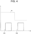
- Fig. 4 shows a relationship between the temperature of the refrigerant flowing through the outdoor heat exchanger and the temperature of the air during the refrigeration cycle operation described above.
- the abscissa in Fig. 4 shows the arrangement direction Z of Figs. 2 and 3 , and the ordinate shows a temperature t.
- the refrigerant flowing through the windward row 101 and the refrigerant flowing through the leeward row 102 have substantially identical temperatures.
- the reason for this is that the refrigerant flowing through the heat exchanger flows in a saturated condition.
- the air exchanges heat with the refrigerant while passing through the windward row 101, leading to a reduction in the temperature thereof.
- the temperature of the fins of the heat exchanger or the surfaces of the heat transfer pipes falls to or below a dew point temperature of the air, dew forms on the surfaces of the fins or the surfaces of the heat transfer pipes, leading to a reduction in the humidity of the air. Accordingly, the temperature and humidity of the air that flows into the leeward row 102 are lower than the temperature and humidity of the air that flows into windward row 101.
- the amount of heat exchange that occurs in the heat exchanger is determined by a difference between the temperature of the refrigerant and the temperature or humidity of the air. Therefore, a larger amount of heat exchange occurs in the windward row 101 than in the leeward row 102.
- the defrosting operation is implemented as follows.
- the four-way valve 11 shown in Fig. 3 is switched such that the high-temperature, high-pressure refrigerant flows to the outdoor heat exchanger 100.
- the refrigerant flows in an opposite direction to the heating operation.
- Fig. 5 shows the temperature of the refrigerant in the outdoor heat exchanger 100 during the defrosting operation.
- the abscissa in Fig. 5 shows time S, and the ordinate shows a refrigerant temperature T.
- a solid line in Fig. 5 denotes a temperature TA1 detected by the first temperature sensor 131 during the defrosting operation
- a dotted line in Fig. 5 denotes an outlet temperature TB of the leeward heat transfer pipes 112 on the leeward row 102.
- the temperature of the windward row 101 to which a large amount of frost is adhered does not increase as easily as the temperature of the leeward row 102. Therefore, if the defrosting operation is terminated at a point where the temperature of the leeward row 102 has increased sufficiently, for example a point (a time SB) where the outlet temperature TB of the leeward row 102 exceeds the defrosting termination temperature Tf, the temperature of the windward row 101 may not yet have increased sufficiently, and as a result, the frost adhered to the windward row 101 may not be removed appropriately.
- the defrosting operation is terminated at a point (a time SA) where the temperature TA1 detected by the first temperature sensor 131, which is disposed between the outlet manifold 127 and the windward fin 113a that is closest to the branch portion 127a of the outlet manifold 127, exceeds the defrosting termination temperature Tf.
- the defrosting operation is continued until the temperature TA1 detected by the first temperature sensor 131 exceeds the defrosting termination temperature Tf.
- the control unit 140 terminates the defrosting temperature on the basis of the temperature detected by the first temperature sensor 131. As a result, the frost adhered to both the windward row 101 and the leeward row 102 can be melted sufficiently.
- the defrosting termination temperature Tf is preferably set appropriately for each individual outdoor heat exchanger in accordance with configuration conditions and use environment conditions thereof.
- the defrosting termination temperature Tf may be set within a temperature range of more than 0 degrees and less than 20 degrees, but is preferably set within a temperature range of more than 5 degrees and less than 20 degrees.
- an amount of remaining frost can be reduced in a multi-row heat exchanger having a distributed thermal load.
- Fig. 6 is a similar view to Fig. 3 , but relates to the second embodiment. Note that except for the parts to be described below, the second embodiment is assumed to be identical to the first embodiment.
- a second temperature sensor 231 is provided.
- the second temperature sensor 231 is disposed between the outlet manifold 127 and a leeward fin 114a that is closest to the branch portion 127a of the outlet manifold 127.
- the second temperature sensor 231 is provided in the outlet branch pipe 125 on the leeward side between the leeward outlet header 106 and the branch portion 127a of the outlet manifold 127.
- the second temperature sensor 231 is also connected to the control unit 140.
- the control unit 140 terminates the defrosting operation when a temperature TA2 (note that the temperature TA2 is identical to the aforementioned temperature TB) detected by the second temperature sensor 231 and the temperature TA1 detected by the first temperature sensor 131 both exceed the set defrosting termination temperature Tf.
- the defrosting operation is terminated when temperature TA2 > defrosting termination temperature Tf and temperature TA1 > defrosting termination temperature Tf are both satisfied.
- an amount of remaining frost can be reduced in a multi-row heat exchanger having a distributed thermal load. Moreover, since the refrigerant temperature on the leeward side can also be detected, the frost adhered to the heat exchanger can be melted more reliably.
- Fig. 7 is a similar view to Fig. 3 , but relates to the third embodiment. Note that except for the parts to be described below, the third embodiment is assumed to be identical to the first embodiment.
- a third temperature sensor 331 is provided.
- the third temperature sensor 331 is disposed in the outlet manifold 127.
- an amount of remaining frost can be reduced in a multi-row heat exchanger having a distributed thermal load.
- the temperature in a portion where the outlet branch pipes 125 converge can be detected during the cooling operation, and as a result, appropriate over-cooling control can be implemented on the refrigeration cycle.
- an air conditioner is used as the refrigeration cycle device, but this invention is not limited thereto, and may be applied widely to any refrigeration cycle device that includes a refrigeration circuit having a compressor, an expansion unit, an indoor heat exchanger, and an outdoor heat exchanger. Accordingly, this invention may be implemented using a hot water supply device, for example, as the refrigeration cycle device.
- the outdoor heat exchanger is a two-row heat exchanger, but this invention is not limited thereto, and may also be applied to a heat exchanger having three or more rows.
- the invention is implemented such that the windward row described above serves as the row furthest toward the windward side in the heat exchanger having three or more rows.
- the configuration of the above embodiments may be taken as merely an example.
- the first temperature sensor may be attached to the windward outlet header.
- the first temperature sensor may be attached to one of the windward heat transfer pipes between the windward outlet header and the windward fin that is closest to the branch portion of the outlet manifold.
- the first temperature sensor is preferably attached to a windward heat transfer pipe positioned on the lower side, and most preferably attached to the windward heat transfer pipe in the lowest position.
Landscapes
- Engineering & Computer Science (AREA)
- Physics & Mathematics (AREA)
- Mechanical Engineering (AREA)
- Thermal Sciences (AREA)
- General Engineering & Computer Science (AREA)
- Heat-Exchange Devices With Radiators And Conduit Assemblies (AREA)
- Other Air-Conditioning Systems (AREA)
Applications Claiming Priority (1)
| Application Number | Priority Date | Filing Date | Title |
|---|---|---|---|
| PCT/JP2015/052689 WO2016121103A1 (fr) | 2015-01-30 | 2015-01-30 | Dispositif à cycle de réfrigération |
Publications (2)
| Publication Number | Publication Date |
|---|---|
| EP3252400A1 true EP3252400A1 (fr) | 2017-12-06 |
| EP3252400A4 EP3252400A4 (fr) | 2018-10-10 |
Family
ID=56542753
Family Applications (1)
| Application Number | Title | Priority Date | Filing Date |
|---|---|---|---|
| EP15880000.3A Withdrawn EP3252400A4 (fr) | 2015-01-30 | 2015-01-30 | Dispositif à cycle de réfrigération |
Country Status (3)
| Country | Link |
|---|---|
| EP (1) | EP3252400A4 (fr) |
| JP (1) | JPWO2016121103A1 (fr) |
| WO (1) | WO2016121103A1 (fr) |
Families Citing this family (1)
| Publication number | Priority date | Publication date | Assignee | Title |
|---|---|---|---|---|
| CN106322847A (zh) * | 2016-10-17 | 2017-01-11 | 珠海格力电器股份有限公司 | 多排换热器和包括该多排换热器的空调器 |
Family Cites Families (19)
| Publication number | Priority date | Publication date | Assignee | Title |
|---|---|---|---|---|
| JPH0434371Y2 (fr) * | 1985-07-12 | 1992-08-17 | ||
| JPS6250467U (fr) * | 1985-09-17 | 1987-03-28 | ||
| JPS6317369A (ja) * | 1986-07-08 | 1988-01-25 | 松下精工株式会社 | 空気調和機 |
| JPS6349673A (ja) * | 1986-08-19 | 1988-03-02 | 松下精工株式会社 | 空気調和機 |
| JPS6369963U (fr) * | 1986-10-22 | 1988-05-11 | ||
| JPS6467577A (en) * | 1987-09-08 | 1989-03-14 | Toshiba Corp | Multiple type heat pump type air conditioner |
| DE3938842A1 (de) * | 1989-06-06 | 1991-05-29 | Thermal Waerme Kaelte Klima | Verfluessiger fuer ein kaeltemittel einer fahrzeugklimaanlage |
| JPH03199857A (ja) * | 1989-12-27 | 1991-08-30 | Toshiba Corp | 空気調和機 |
| JP3004676B2 (ja) * | 1990-04-20 | 2000-01-31 | 株式会社日立製作所 | 冷凍サイクル装置 |
| JPH04110576A (ja) * | 1990-08-31 | 1992-04-13 | Toshiba Corp | ヒートポンプ式空気調和装置 |
| JPH0861799A (ja) * | 1994-08-26 | 1996-03-08 | Sharp Corp | 空気調和機 |
| JP3086181B2 (ja) * | 1996-10-16 | 2000-09-11 | ホシザキ電機株式会社 | 冷却貯蔵庫 |
| JP2003185307A (ja) * | 2001-12-20 | 2003-07-03 | Fujitsu General Ltd | 空気調和機の制御装置 |
| JP2005226866A (ja) * | 2004-02-10 | 2005-08-25 | Denso Corp | 冷凍サイクル装置 |
| JP2006284134A (ja) * | 2005-04-04 | 2006-10-19 | Matsushita Electric Ind Co Ltd | 熱交換器 |
| JP2006322691A (ja) * | 2005-05-20 | 2006-11-30 | Denso Corp | エジェクタサイクル |
| JP4874223B2 (ja) * | 2007-12-25 | 2012-02-15 | 三菱電機株式会社 | 空気調和機 |
| KR101572845B1 (ko) * | 2009-08-19 | 2015-11-30 | 엘지전자 주식회사 | 공기조화기 |
| JP2014066420A (ja) * | 2012-09-26 | 2014-04-17 | Hitachi Appliances Inc | 冷凍装置 |
-
2015
- 2015-01-30 EP EP15880000.3A patent/EP3252400A4/fr not_active Withdrawn
- 2015-01-30 JP JP2016571640A patent/JPWO2016121103A1/ja active Pending
- 2015-01-30 WO PCT/JP2015/052689 patent/WO2016121103A1/fr not_active Ceased
Also Published As
| Publication number | Publication date |
|---|---|
| WO2016121103A1 (fr) | 2016-08-04 |
| EP3252400A4 (fr) | 2018-10-10 |
| JPWO2016121103A1 (ja) | 2017-04-27 |
Similar Documents
| Publication | Publication Date | Title |
|---|---|---|
| CN109328287B (zh) | 制冷循环装置 | |
| EP3064881B1 (fr) | Échangeur thermique et climatiseur | |
| EP2674717B1 (fr) | Échangeur de chaleur pour climatiseur | |
| US10156400B2 (en) | Heat exchanger and refrigeration cycle device | |
| CN109154460B (zh) | 层叠型集管、热交换器和空调装置 | |
| JP5404489B2 (ja) | 空気調和機 | |
| US20110127015A1 (en) | Microchannel heat exchanger module design to reduce water entrapment | |
| EP2304340B1 (fr) | Procédure de démarrage pour systèmes frigorifiques munis d'un condenseur à micro-canaux et d'un cycle de réchauffage | |
| EP3156752B1 (fr) | Échangeur thermique | |
| EP3540318A1 (fr) | Unité intérieure pour climatiseur, et climatiseur | |
| US9618235B2 (en) | Air conditioner including an indoor auxiliary heat exchanger | |
| JP2005214533A (ja) | 除湿機 | |
| JP4889011B2 (ja) | 冷暖房空調システム | |
| JP2009030852A (ja) | 空気調和機 | |
| JP6045204B2 (ja) | 熱交換システム | |
| EP3252400A1 (fr) | Dispositif à cycle de réfrigération | |
| JP5636676B2 (ja) | 空気調和機 | |
| CN108224602A (zh) | 用于空调室外换热器的分歧管和空调器 | |
| JP5677237B2 (ja) | 空気調和機 | |
| JP2013253726A5 (fr) | ||
| KR20100131658A (ko) | 분배기 및 이를 포함하는 공기 조화기 | |
| CN117355721A (zh) | 热交换器、具备热交换器的空调装置的室外机、以及具备空调装置的室外机的空调装置 | |
| JPH10253188A (ja) | 空気調和装置 | |
| CN115751485B (zh) | 室外换热器结构、包含其的空调系统及控制方法 | |
| WO2011111602A1 (fr) | Climatiseur |
Legal Events
| Date | Code | Title | Description |
|---|---|---|---|
| PUAI | Public reference made under article 153(3) epc to a published international application that has entered the european phase |
Free format text: ORIGINAL CODE: 0009012 |
|
| 17P | Request for examination filed |
Effective date: 20170515 |
|
| AK | Designated contracting states |
Kind code of ref document: A1 Designated state(s): AL AT BE BG CH CY CZ DE DK EE ES FI FR GB GR HR HU IE IS IT LI LT LU LV MC MK MT NL NO PL PT RO RS SE SI SK SM TR |
|
| AX | Request for extension of the european patent |
Extension state: BA ME |
|
| DAX | Request for extension of the european patent (deleted) | ||
| A4 | Supplementary search report drawn up and despatched |
Effective date: 20180906 |
|
| RIC1 | Information provided on ipc code assigned before grant |
Ipc: F25B 47/02 20060101AFI20180901BHEP Ipc: F25B 41/00 20060101ALI20180901BHEP Ipc: F25B 13/00 20060101ALI20180901BHEP Ipc: F28F 9/02 20060101ALI20180901BHEP Ipc: F28F 27/00 20060101ALI20180901BHEP Ipc: F28D 1/053 20060101ALI20180901BHEP |
|
| STAA | Information on the status of an ep patent application or granted ep patent |
Free format text: STATUS: THE APPLICATION IS DEEMED TO BE WITHDRAWN |
|
| 18D | Application deemed to be withdrawn |
Effective date: 20190406 |