EP3252461B1 - Système de mesure magnétique ultrasensible basé sur un biocapteur planaire à effet hall (phr) et procédé pour mesurer de faibles concentrations de bioparticules spécifiques et quantifier des interactions de bio-particules - Google Patents
Système de mesure magnétique ultrasensible basé sur un biocapteur planaire à effet hall (phr) et procédé pour mesurer de faibles concentrations de bioparticules spécifiques et quantifier des interactions de bio-particules Download PDFInfo
- Publication number
- EP3252461B1 EP3252461B1 EP16305639.3A EP16305639A EP3252461B1 EP 3252461 B1 EP3252461 B1 EP 3252461B1 EP 16305639 A EP16305639 A EP 16305639A EP 3252461 B1 EP3252461 B1 EP 3252461B1
- Authority
- EP
- European Patent Office
- Prior art keywords
- magnetic
- magnetic field
- particles
- track
- bio
- Prior art date
- Legal status (The legal status is an assumption and is not a legal conclusion. Google has not performed a legal analysis and makes no representation as to the accuracy of the status listed.)
- Active
Links
Images






Classifications
-
- G—PHYSICS
- G01—MEASURING; TESTING
- G01N—INVESTIGATING OR ANALYSING MATERIALS BY DETERMINING THEIR CHEMICAL OR PHYSICAL PROPERTIES
- G01N27/00—Investigating or analysing materials by the use of electric, electrochemical, or magnetic means
- G01N27/72—Investigating or analysing materials by the use of electric, electrochemical, or magnetic means by investigating magnetic variables
- G01N27/74—Investigating or analysing materials by the use of electric, electrochemical, or magnetic means by investigating magnetic variables of fluids
- G01N27/745—Investigating or analysing materials by the use of electric, electrochemical, or magnetic means by investigating magnetic variables of fluids for detecting magnetic beads used in biochemical assays
-
- G—PHYSICS
- G01—MEASURING; TESTING
- G01N—INVESTIGATING OR ANALYSING MATERIALS BY DETERMINING THEIR CHEMICAL OR PHYSICAL PROPERTIES
- G01N33/00—Investigating or analysing materials by specific methods not covered by groups G01N1/00 - G01N31/00
- G01N33/48—Biological material, e.g. blood, urine; Haemocytometers
- G01N33/50—Chemical analysis of biological material, e.g. blood, urine; Testing involving biospecific ligand binding methods; Immunological testing
- G01N33/53—Immunoassay; Biospecific binding assay; Materials therefor
- G01N33/543—Immunoassay; Biospecific binding assay; Materials therefor with an insoluble carrier for immobilising immunochemicals
- G01N33/54313—Immunoassay; Biospecific binding assay; Materials therefor with an insoluble carrier for immobilising immunochemicals the carrier being characterised by its particulate form
- G01N33/54326—Magnetic particles
-
- G—PHYSICS
- G01—MEASURING; TESTING
- G01N—INVESTIGATING OR ANALYSING MATERIALS BY DETERMINING THEIR CHEMICAL OR PHYSICAL PROPERTIES
- G01N33/00—Investigating or analysing materials by specific methods not covered by groups G01N1/00 - G01N31/00
- G01N33/48—Biological material, e.g. blood, urine; Haemocytometers
- G01N33/50—Chemical analysis of biological material, e.g. blood, urine; Testing involving biospecific ligand binding methods; Immunological testing
- G01N33/53—Immunoassay; Biospecific binding assay; Materials therefor
- G01N33/543—Immunoassay; Biospecific binding assay; Materials therefor with an insoluble carrier for immobilising immunochemicals
- G01N33/54366—Apparatus specially adapted for solid-phase testing
Definitions
- the present invention concerns a magnetic measurement system based on an ultrasensitive Planar Hall magnetoresistive biosensor(s) for measuring low concentrations down to femtomoles of specific bio-particles contained in a solution and/or quantifying the said bio-particles interactions.
- the invention also relates to a method using the magnetic measurement system according to the invention for measuring low concentrations down to femtomoles of bio-particles contained in a solution and quantifying the interactions of the specific bio-particles, in particular for concentrations ranging from nano-moles to pico-moles wherein the Van der Waals repulsive forces have to be taken account.
- Aptamers are short strands of nucleotides (single strand DNA and RNA) that can bind with high affinity and specificity to targets ranging from cells to proteins and from proteins to small molecules.
- aptamers have been selected for various targets from a large random sequence pool and have been created by an in vitro process that includes repeated rounds of binding, partition and amplification and that is known as systematic evolution of ligands by exponential enrichment (SELEX).
- aptamers exhibit several unique features, including ease chemical modification, reversible folding, and excellent stability, which is beneficial to the development of affinity binding assays. Aptamers play a significant role in disease research and clinical diagnosis, due to the long term stability of the DNA probe.
- thrombin is a serine protease known as a key enzyme responsible for the conversion of fibrinogen to fibrin in the blood coagulation and wound healing processes.
- thrombin is present in its inactive form prothrombin in blood.
- thrombin is activated immediately to cleave fibrinogen and form clots preventing bleeding.
- Thrombin concentration plays a crucial role in physiological and pathological conditions, and is an essential marker for the diagnosis of various diseases, i.e. Alzheimer, cardiovascular disease, and cancers. Therefore, the development of devices and methods for the monitoring and detection of low bio-molecular concentrations, in particular low thrombin concentrations, with high sensitivity and selectivity is of enormous importance in medical applications.
- DNA-aptamer based techniques for thrombin detection have been used and are reviewed in the article from Bin Deng et al., entitled “Aptamer binding assays for proteins: the thrombin example - A review", published in Analytica Chimica Acta 837 (2014) 1-15 .
- fluorescence, surface plasma resonance, quartz crystal microbalance and electrochemistry can be cited.
- MR sensors are low-power consumptions sensors, they are highly sensitive, easily scalable, inexpensive and portable.
- MR sensors such as semiconductor Hall sensor, anisotropic magnetoresistive (AMR), giant magnetoresistive (GMR), tunneling magnetoresistive (TMR) and giant magneto-impedance (GMI) sensors for bio-sensing application, especially detection of lower thrombin molecular concentrations have been described in several papers.
- PHR Planar Hall Magnetoresistive
- the article from Sinha et al. describes the development of a sensitive aptamer-based PHR sensor for human ⁇ -thrombin detection.
- the sensing mechanism is based on the sandwich-type aptamer assay.
- the sensor surface is modified with thiol-labeled primary aptamer, and then thrombin is applied to the aptamer immobilized surface.
- biotin-labeled secondary aptamer is used to bind with thrombin.
- streptavidin-coated magnetic nanoparticles are used to measure the MR signal.
- the MR signal is measured by the changes in the thrombin concentration which results in the changes in the amount of biotin-labeled secondary aptamer for the binding of streptavidin-coated magnetic nanoparticles in the assay.
- a minimum concentration detection of 86 pM has been achieved with this aptamer-based PHR sensor.
- a first technical problem is to provide a magnetic measurement system based on an ultrasensitive Planar Hall magnetoresistive biosensor and a corresponding method for measuring low concentrations of specific bio-particles that improves the minimum concentration detection level or the minimum concentration detection threshold of the said specific bio-particles contained in a given solution in view of the existing magnetic measurement system and measurement methods based on ultrasensitive Planar Hall magnetoresistive biosensor(s).
- a second technical problem connected to the first technical problem, is to provide a method for quantifying interactions of specific bio-particles contained in a given solution, in particular in the solutions having concentrations ranging from nano-moles to pico-moles and wherein the Van der Waals repulsive forces have to be taken account.
- the invention aims at solving the first technical problem and the second technical problem.
- the invention relates to a magnetic measurement system for measuring a concentration of specific bio-particles through a sensitive detection of magnetic labeled particle(s), the magnetic measurement system comprising:
- the magnetic measurement system might incorporate one or several of the following features, taken in any technically admissible combination:
- the invention also relates to a magnetic measurement method for measuring low concentrations of bio-particles contained in a given solution and/or quantifying the interactions of the said specific bio-particles contained in a given solution, in particular in solutions having concentrations ranging from nano-moles to pico-moles, the magnetic measuring method comprising the steps of:
- the magnetic measurement method might incorporate one or several of the following features, taken in any technically admissible combination:
- a magnetic measurement system 2 also called a micromagnetometry system, is configured for measuring low concentration of specific bio-particles through an ultrasensitive detection of magnetic particle labels.
- bio-particles shall be broadly interpreted as a particles intervening in a biological process and having a small size ranging from the cell down to a single bio-molecule.
- the set of bio-particles includes the cells, the bacteria, the viruses, the bio-inspired architectures or assemblies, the bio-molecules from cell size to nano-size biological assemblies, the bio-labeled nanoparticles, the aptamer molecules, the genes/antigens, the antibodies, the vectorized nanoparticles, and the target bio-molecules.
- the set of bio-particles includes core/shell hybrid particles from cell size to nano-size, wherein the core or the shell or both are bio-labelled, wherein the core can be magnetic or bi-stable particle or silica gel or silica aerogel, the core, and wherein the shell can be a bio-inspired architecture and bio-hybrid particles.
- the magnetic measurement system 2 is configured to detect the presence of at least one single magnetic label.
- the magnetic particle labels are comprised in a set including metallic materials, metallic oxides, rare earth elements, organometallic complexes, coordination complexes (magnetic molecules, magnet chains).
- the magnetic measurement system 2 comprises an aptamer-based magnetic hybrid AMR/PHR sensor 12, an electrical current source 14, a voltage measurement device 16, a magnetic element 18 and a signal treatment device 20.
- the magnetic AMR/PHR sensor 12 is named sensor 12 in the remainder of the description.
- the sensor 12 is a sensor adapted to detect AMR and PHR, PHR being an acronym for Planar Hall Resistance.
- the Planar Hall Resistance is based on the planar Hall effect of ferromagnetic materials. It measures the change in anisotropic magnetoresistance caused by an external magnetic field in the Hall geometry. The sensor responds to magnetic field components in the sensor plane as opposed to the ordinary Hall sensor, which measures field components perpendicular to the sensor plane. Hence, the used name "planar Hall". Generally speaking, for ferromagnetic materials, the resistance is larger when the current flows along the direction of magnetization than when it flows perpendicularly to the magnetization vector. This creates an asymmetric electric field perpendicular to the current, which depends on the magnetization state of the sensor.
- AMR is an acronym for Anisotropic Magneto-Resistance.
- Magneto-resistance is the property of a material to change the value of the electrical resistance of the material when an external magnetic field is applied to the material. More specifically, anisotropic magnetoresistance is a property of a material in which a dependence of electrical resistance on the angle between the direction of electric current and direction of magnetization is observed. The effect arises from the simultaneous action of magnetization and spin-orbit interaction and its detailed mechanism depends on the material. It can be for example due to a larger probability of s-d scattering of electrons in the direction of magnetization (which is controlled by the applied magnetic field). The net effect (in most materials) is that the electrical resistance has maximum value when the direction of current is parallel to the applied magnetic field.
- the sensor 12 comprises an active surface 22 that includes a magnetic track 24 with a closed loop shape deposited on a substrate 26.
- the active surface 22 has been previously prepared by covering the said surface 22 by sandwich-type aptamer structures 27 that include individually a specific captured bio-molecule.
- the active surface has been firstly modified with thiol-labeled primary aptamer, and then specific bioparticles contained in a solution at a concentration to be determined are applied to the aptamer immobilized surface. After that, biotin-labeled secondary aptamers are used to bind with the specific bio-molecules.
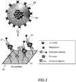
- the active surface 22 is ready to bind streptavidin-coated magnetic particles forming magnetic labels 28 to the sandwich-type aptamer structures 27 as shown in Figure 2 wherein the specific bioparticle is thrombin as an example.
- a magnetic label or particle 28 drawn to scale comprises a dozen or more iron-oxide cores 29 embedded in a dextran polymer functionalize with Streptadivin.
- the magnetic labels 28 may be bound to the sandwich-type aptmer structures 27 before the measurement is carried out.
- the magnetic labels 28 shall be applied to the sandwich-type aptamer structures 27 covering the active surface when the magnetic MR signal measurement has started since determining the saturation time from the binding kinetics of the magnetic particles is needed.
- the magnetic labels or magnetic particles 28 to be detected are motionless and placed close to the active surface 22 of the sensor 12 when they are bound to the sandwich-type aptamer structures 27.
- the magnetic particles 28 are bound to the specific bio-particles to be detected by means of secondary specific aptamers, the specific bio-particles being themselves bound to the active surface 22 and especially the magnetic track 24 by means of primary aptamers.
- the number of magnetic particles 28 on the magnetic track 28 equals the number of bio-particles to be detected, so the detection of the number of magnetic particles 28 on the magnetic track 24 allows determining the number of the specific bio-particles bound to the active surface 22.
- the sensor 12 has a first current terminal 30 and a second current terminal 32 forming a pair of terminals which face each other contacting with the closed loop magnetic track 24.
- the sensor 12 also has a first voltage terminal 34 and a second voltage terminal 36 forming a pair of terminals which face each other contacting with the closed loop magnetic track 24.
- the sensor 12 also has a first axis 40 or easy axis passing through the first and second current terminals 30, 32 being parallel to the exchange bias field direction of the material and perpendicular to a second axis 42 or hard axis passing through the first and second voltage terminals 34, 36.
- the senor 12 is based on a multi-ring architecture and is manufactured using a lithography technique in a clean-room of class 1000 with a lift-off process.
- the magnetic track 24 is a tri-layered material, including a ferromagnetic film, a metal and an anti-ferromagnetic film, for example Ta(5)/NiFe(10)/Cu(0.1)/IrMn(10)/Ta(5) (nm).
- the soft magnetic layer NiFe is the sensing material that is weakly coupled to an anti-ferromagnetic layer (IrMn) by a long range exchange bias field through an atomic Cu sub layer.
- the tri-layer structure Ta(5)/NiFe(10)/Cu(0.1)/IrMn(10)/Ta(5) nm is deposited by a 6 gun-magnetron sputtering system with a based vacuum of about 10 -8 Torr.
- the magnetic sensor is passivated by a Si 2 O 3 or Si 3 N 4 /Si 2 O 3 bi-layer with a thickness of 200 nanometers.
- the outer diameter of the sensor 12 is equal here to 300 ⁇ m and the width w of the magnetic track 24 is equal to 10 ⁇ m.
- the magnetic track 24 of the sensor 12 has a first arm 102 made of a first set of a predetermined ring number m of circular meander paths 104 delimited within a first quarter surface 106 of the sensor 12, the outermost meander path 108 being connected to the first current terminal 30 and the innermost meander path 110 being connected to the first voltage terminal 34.
- the ring number m is an integer comprised between 1 and 17.
- the magnetic track 24 of the sensor 12 further comprises a second arm 112 made of a second set of the same predetermined number m of circular meander paths 114 delimited within a second quarter surface 116 of the sensor 12, the outermost meander path 118 being connected to the second current terminal 32 and the innermost meander path 120 being connected to the first voltage terminal 34.
- the magnetic track 24 of the sensor 12 also comprises a third arm 122 made of a third set of the same ring number m of circular meander paths 124 delimited within a third quarter surface 126 of the sensor 12, the outermost meander path 128 being connected to the second current terminal 32 and the innermost meander path 130 being connected to the second voltage terminal 36.
- the magnetic track 24 of the sensor 12 further comprises a fourth arm made 132 of a fourth set of the same ring number m of circular meander paths 134 delimited within a fourth quarter surface 136 of the magnetic sensor 12, the outermost meander path 138 being connected to the first current terminal 30 and the innermost meander path 140 being connected to the second voltage terminal 36.
- This multi-ring architecture enhances the sensitivity of the sensor 12 in a compact region.
- the sign of the calculated value for path 1 and 2 is the same, which means that AMR effect for both currents is additive.
- the maximum voltage variation in the profiles and accordingly the field sensitivity of the arm resistance increases the ring number.
- the voltage profile for the full magnetic ring is a linear response across zero field, where the AMR/PHR voltage of the ring are additive for all junction components
- the sensitivity of first magnetic sensor is enhanced by using a tri-layer structure which has a small exchange coupling field and high active current.
- This multi-ring architecture enhances the field sensitivity and the active area of the sensor 12.
- the senor 12 is a highly sensitive magneto-resistive (MR) sensor based on Planar Hall Effect (PHE) that is capable to detect the presence of magnetic particles 28 closely bound to the active surface 22 through the sandwich-type aptamer structures 27, to quantify therefore the number of immobilized magnetic particles 28, and to determine the concentration of bio-particles of the solution.
- MR magneto-resistive
- PHE Planar Hall Effect
- the ring number m of circular meander paths is comprised between 9 and 17.
- each arm has eleven meander paths or quarters of circular rings, this number maximizing the sensitivity of the sensor 12.
- the first electrical current or voltage source 14, connected between the first and second current terminals, is configured to inject a DC bias current for the sensor 12.
- the electrical DC bias current source is for example a Keithley 2400 current source and the amplitude of the DC bias current is set to 1 mA.
- the voltage measurement device 16 connected between the first voltage terminal 34 and the second voltage terminal 36, is configured to measure the differential voltage V MR between the pair of voltage terminals 34, 36.
- the voltage measurement device 16 comprises a low noise amplifier 44 with a gain of 20 dB for amplifying the detected differential voltage.
- the magnetic element 18 is configured to apply a constant magnetic field H DC on the magnetic track 24.
- the magnetic element 18 is comprised in the set consisting of the single coils, the pair of Helmholtz coils, a plurality of coils, and the permanent magnets.
- the magnetic element 18 is a pair of Helmholtz coils supplied by a DC coil electrical source 45.
- the actual amplitude H of the applied DC constant magnetic field by is chosen to be closely located in a vicinity of an optimum amplitude of the permanent DC magnetic field comprised in a set of two optimum values H1, H2 of the permanent DC magnetic field, each optimum value H1, H2 maximizing locally the absolute value of a first quantity H ⁇ ⁇ V MR ⁇ H , where H is the amplitude of the applied magnetic field and ⁇ V MR ⁇ H is the derivate of the differential voltage with respect to the magnetic field at the applied field H.
- the presence of the magnetic particles 28 on the magnetic track 24 results in a voltage change which depends on the number of magnetic particles 28 bound closely to the magnetic track 24. Especially, the magnetic particles 28 become magnetized when the external DC magnetic field is applied by the magnetic element 18. Their presence in close proximity of the sensor surface 22 alters the local magnetic field and consequently changes the output voltage of the magnetic sensor 12.
- H stray k n ⁇ V particle 4 ⁇ z 3 H
- ⁇ is a constant equal to 1 ⁇ k n ⁇ v particle 4 ⁇ z 3
- H is the constant DC magnetic field applied
- V MR is the measured differential magnetoresistive voltage
- ⁇ V MR ⁇ H is the derivate of the magnetoresistive voltage with respect to the magnetic field at the actual applied field H, this derivate corresponding to the field-sensitivity i.e. the sensor sensitivity S(H).
- the amplitude of the actual amplitude H of the applied DC constant magnetic field by is chosen to be closely located in a vicinity of an optimum amplitude of the permanent DC magnetic field comprised in a set of two optimum values H1, H2 of the permanent DC magnetic field, each optimum value H1, H2 maximizing locally the absolute value of a first quantity H ⁇ ⁇ V MR ⁇ H .
- the sensor 12 has the highest sensitivity in detection of the magnetic particles 28 at these two maximal fields H 1 and H 2 .
- the magnitudes of these two fields are dependent on the exchange bias H ex and coercivity fields H k of the sensor stack.
- the voltage changes ⁇ V are equal.
- the amplitude of the constant magnetic field applied to the magnetic coil 18 is preferably selected around these values H 1 and H 2 in respective vicinities 218, 210.
- the diameter of the vicinity 218, 210 surrounding the optimum amplitudes H1 and H2, of the permanent DC magnetic field is lower than a first predetermined threshold so that a first ratio of the absolute value of the first quantity H ⁇ ⁇ V MR ⁇ H at the actual amplitude of the applied DC constant magnetic field over the maximum absolute value of the quantity H ⁇ ⁇ V MR ⁇ H at the corresponding optimum amplitude H1 or H2 is lower than minus 3 dB.
- the diameter of the vicinities 218 and 210 is chosen to be respectively equal to 10 and 20 Oe, the amplitude of the applied constant magnetic field being comprised between 5 Oe and 15 Oe, or between 30 Oe and 50 Oe.
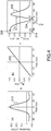
- the first curve 202 can be constructed by multiplying a second curve 212, as shown in the view 4-(a), of the evolution S(H) of the sensitivity S of the sensor 12 versus the applied constant field H by a third curve 222, as shown in the view 4-(b), of the evolution the stray field of particles H stray versus the applied constant field H.
- the second curve 212 is deduced from experimental measurement of the sensor carried out by using the exemplary test sensor as described in the "Test and performance results" section.
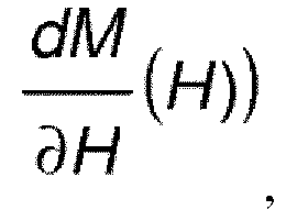
- the local optimum amplitude H2 of the permanent DC magnetic field closest to the actual amplitude of the applied DC constant magnetic field is selected among the two optimum amplitudes H1, H2 of the set as the local optimum amplitude that maximizes a second quantity H ⁇ ⁇ V MR ⁇ H / BN H defined as the ratio of the first quantity H ⁇ ⁇ V MR ⁇ H to the Barkhausen noise level BN(H) at the applied field, the Barkhausen noise being proportional to dM ⁇ H H ) , where M is the magnetization of the magnetic sensor.
- the diameter of the vicinity surrounding the optimum amplitude H1 or H2 of the permanent DC magnetic field is lower than a second predetermined threshold so that a second ratio of the absolute value of a second quantity H ⁇ ⁇ V MR ⁇ H / BN H at the actual amplitude of the applied DC constant magnetic field over the maximum absolute value of the second quantity H ⁇ ⁇ V MR ⁇ H / BN H at the corresponding optimum amplitude H1 or H2 is lower than minus 3 dB, the second quantity H ⁇ ⁇ V MR ⁇ H / BN H being defined as the ratio of the first quantity H ⁇ ⁇ V MR ⁇ H to the Barkhausen noise level BN(H) at the applied field, the Barkhausen noise being proportional to dM ⁇ H H ) , where M is the magnetization of the magnetic sensor.
- the noises of a biosensor are required to be minimized to increase the signal-to-noise (Su/N) ratio of the detection of magnetic particles 28 by the sensor 12, wherein the useful detection signal Su is the voltage change ⁇ V and N is the noise.
- 1/f noise can be minimized by using an alternative AC exciting field and by choosing an exciting frequency higher than the frequency knee.
- Thermal noise of the sensor 12 having a diagonal configuration is smaller than other off-diagonal configuration sensors such as GMR, MTJ.
- the transverse resistivity is sensitive only to the anisotropic resistivity, and not to the isotropic resistivity term.
- noises of a PHE sensor is about four orders of magnitude smaller than the noise of a similar longitudinal anisotropic magnetoresistance (AMR) sensor only.
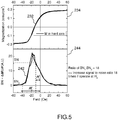
- Barkhausen noise at field H is proportional to dM ⁇ H , i.e. the derivative of the magnetization M with respect to the magnetic field H applied for magnetization on the magnetic track 24.
- a first curve 232 of the evolution M(H) of the magnetization M of the tested magnetic sensor 12 versus the applied constant field H is shown in the top view 234, while a second curve 242 of the evolution of the derivation dM/dH(H) versus the applied constant field H is shown in the bottom view 244.
- the derivative dM/dH(H 1 ) at H 1 is about 18 times higher than the derivative dM/dH(H 2 ) at H 2 as shown on the second curve 242.
- the Barkhausen noise at H 2 is smaller than at H 1 , which results in a higher SU/N ratio when detecting the magnetic particles 28.
- Barkhausen noise of the sensor 12 the inventors applied an AC magnetic field 5 Oe rms at frequency of 113.7 Hz, and recorded voltage variations are at two bias DC magnetic fields H 1 and H 2 .
- the root-means-square of the voltage noise ( ⁇ V Barkhausen ) are measured to be about 309.8 nV and 60.07 nV respectively.
- the ratio Su/N at H 2 is found 5.15 times higher than the ratio Su/N at H 1 .
- the limit or the threshold of detection (LOD) of the particle attainable by the measurement system 2 is lowered.
- the signal processing device 20 is adapted to deduce at least one physical quantity based on the differential voltage measured by the voltage measurement device 16.
- the signal processing device 20 is further configured to deduce at least one physical quantity based on the extracted amplitude.
- the physical quantity is relative to the at least one single magnetic particle 28.
- the physical quantity is relative to the number of magnetic particles 28 bound closely to the magnetic track 24 through sandwich-type aptamer structures 27, hence the concentration of the specific bio-particles of the solution.
- the single ring or multi-ring architecture advantageously provides with high sensing performance due to the Wheastone bridge electrical configuration.
- the signal processing device 20 comprises a processor 48 but does not include a lock-in unit.
- the processor 48 is configured to process the amplitude of the magnetic measured signal V MR and to determine at least one physical quantity based on the differential voltage V MR and representative of the bio-molecules concentration.
- the processor 48 is configured for detecting and quantifying from a set of different differential voltages V MR (t), measured by the voltage measurement device 16 and sampled at different time t, a magnetic flux change representative of the kinetics of the binding of the magnetic particle 28 close to the active surface 22 of the sensor 12 through the binding to the sandwich-type aptamer structures 27.
- the measurement system may further include an environmental temperature sensor 50 and a temperature controller 52.
- the environmental temperature sensor 50 is configured to measure a temperature representative of the actual environmental temperature T of the magnetic particles 28 and the sensor 12, preferably located close to the active surface 22 of the sensor 12.
- the environmental temperature sensor 16 is a platinum resistance of 100 Ohms.
- the temperature controller 52 is adapted to control and/or to regulate the environmental temperature of the magnetic particles 28. More specifically, the temperature controller is configured to heat by a heater 54 in a controlled way the environment of the active surface 22 and the magnetic particles 28.
- the heater 54 is for instance a Peltier heat sink element attached to the first magnetic sensor 4 and connected to a temperature controller 56 that can control the environmental temperature T variation by varying the temperature T from 77 K to 690 K.
- the sensitivity of the measurement system 2 is improved, thus allowing the detection of a very small number of magnetic particles 28 on the magnetic track 24.
- respective magnetic measurement systems 302, 312 are derived from the magnetic measurement by sharing common elements, in particular the aptamer-based magnetic hybrid AMR/PHR sensor 12 and the magnetic element 18, configured to apply the applied DC constant magnetic field at an actual amplitude closely located in a vicinity of one of the optimum amplitudes among the two optimum values H1 and H2
- the two variants 302, 312 of the second embodiment of the magnetic measurement system differs from the magnetic measurement system 2 according to the first embodiment in that they comprise further an AC magnetic field source 314, 316 for applying an actual AC alternative magnetic field on the magnetic track 24 at a predetermined amplitude and at a predetermined frequency, the applied actual AC alternative magnetic field being collinear and added to the actual constant DC magnetic field applied by the magnetic element.
- the predetermined frequency of the applied AC alternative magnetic field is ranging from 10 Hz to 3 kHz.
- an alternative magnetic field H AC superimposed to the constant magnetic field H DC allows the sensor 12 to operate at its maximum sensitivity when detecting magnetic particle bound close to the magnetic track 24, and to lock in with an alternative measured voltage signal at a suitable frequency for further minimizing the measurement noise.
- the AC magnetic field source 314 of the magnetic measurement system 302 is an external AC magnetic source that comprises here a second AC coil current source 316 supplying a AC current oscillating at the frequency of 100 Hz, and at least one coil, here two Helmholtz coils 318, connected to the second AC coil current source 316.
- the magnetic measurement system 302 differs from the magnetic measurement system 2 of the Figure 1 in that the signal processing device 20 is replaced by a signal processing device 320 that comprises further to the processor 48 a lock-in unit 326.
- the lock-in unit 326 is configured to lock the amplified measured differential voltage signal onto the magnetic alternating excitation field signal by using a phase lock loop and to detect the peak measured differential voltage measured at the output of the pair of voltage terminals 34, 36.
- the lock-in unit 46 is configured to extract the amplitude at twice the exciting frequency in the differential voltage measured by the voltage measurement device 16.
- the processor 48 is configured to process the amplitude extracted by the lock-in unit 46 and to determine at least one physical quantity based on the extracted amplitude, representative of the quantity of the magnetic particles 28 bound close to the active surface 22 of the sensor 12 at the time of measurement and representative of the bio-particles concentration when the saturation time of the binding of the magnetic particles has been reached.
- the processor 48 is configured for detecting and quantifying from a set of the peak amplitudes Vp (t) of the measured differential voltages extracted by the lock-in unit 326 and sampled at different time t, a magnetic flux change representative of the kinetics of the binding of the magnetic particles 28 close to the active surface 22 of the sensor 12 through the binding to the sandwich-type aptamer structures 27.
- the AC magnetic field source 316 of the magnetic measurement system 312 comprises an electrical AC bias current source 334 and the magnetic track 24.
- the electrical AC bias current source 334 replaces here the electrical DC bias current source 14 of the magnetic measurement systems 2, 302 of the Figures 1 and 6 , and is configured to inject an alternative AC bias current in the magnetic track 24 at a constant predetermined frequency ranging from 5 Hz to 10 kHz, here set ot 100 Hz.
- the magnetic track 24 of the first magnetic 12 supplied with an alternating bias current AC by the AC bias current source 334 generates a magnetic excitation field H AC that modulates the actual constant DC magnetic field H DC applied by the magnetic element 18 at an actual amplitude closely located in a vicinity of one of the two optimum amplitudes H1 and H2.
- the intensity of the alternating bias current is chosen high enough so that the range of the amplitude of the total magnetic excitation field H actually applied includes a single optimum value among H1 et H2, and is chosen low enough so that the total magnetic excitation field H actually applied is kept closest to the optimum value H1 or H2.
- the electrical AC bias current source 334 is for example a Keithley 6221 AC Current source or Agilent 33522A voltage source and the amplitude of the AC bias current being set equal to 1 mA rms , the term “rms" standing for "root means square".
- the processor 48 is configured in the same way as described for the magnetic measurement system 302 of the first variant.
- the measurement magnetic system comprises in variants one or several of the following features:
- the magnetic measurement system comprises two AMR/PHR magnetic sensors having a same magnetic structure and a same shape amongst the cross shape, the single ring closed loop shape, or the multi-ring with four arms shape.
- a magnetic measuring method 402 for measuring low concentrations of bio-particles contained in a given solution and/or quantifying the interactions of specific bio-particles contained in a solute at an unknown concentration, in particular for concentrations ranging from nano-moles to pico-moles comprises several steps.
- a magnetic measurement system configured for measuring concentration of bio-particles through a sensitive detection of magnetic particle labels, is provided, as for example the magnetic measurement systems 2, 302, 312 respectively described in the Figures 1 , 6 and 7 .
- the magnetic measurement system comprises:
- an electrical bias current is injected permanently in the magnetic track 24 by using the electrical bias current source 14 connected between the first and second current terminals 30, 32.
- an actual DC constant magnetic field is applied permanently on the magnetic track 24 at predetermined amplitude by using a magnetic element 18.
- a differential voltage V MR between the pair of voltage terminals 34, 36 is measured by a voltage measurement device 16 connected between the first and second voltage terminals 34, 36.
- a fifth step 412 at least one physical quantity is determined by the signal processing device 20 on the basis of the measured differential voltage, the physical quantity being representative of the bio-particles concentration.
- the magnetic measurement method 402 is characterized in that the actual amplitude of the applied DC constant magnetic field is closely located in a vicinity of an optimum amplitude of the permanent DC magnetic field comprised in a set of two optimum values H1, H2 of the permanent DC magnetic field, each optimum value H1, H2 maximizing locally the absolute value of a first quantity H ⁇ ⁇ V MR ⁇ H , where H is the amplitude of the applied magnetic field and ⁇ V MR ⁇ H is the derivate of the differential voltage with respect to the magnetic field at the applied field H.
- the magnetic measurement method is also characterized in that the said method comprises a sixth step 414 of applying on the prepared active surface 22 a drop of a magnetic solution containing streptavidin-coated magnetic nanoparticles at a saturated concentration in regard of the concentration of the specific bio-molecules to be determined.
- the sixth step is preferably applied before the measurement step, i.e the fourth step 410, the measurement step 414 being started once the saturation time of the binding of the magnetic particles to the sandwich a sandwich-type aptamer structures 27 being attained.
- the sixth step 414 is executed after the start of the second and third steps 410, 412 of injecting a bias current in the magnetic track and applying the actual constant magnetic field and after starting the fourth step of measuring the differential voltage V MR until at least the saturation time of the binding of the magnetic particles to the sandwich-type aptamer structures 27 is achieved.
- the local optimum amplitude H2 of the permanent DC magnetic field closest to the actual amplitude of the applied DC constant magnetic field is selected among the two optimum amplitudes H1, H2 as the local optimum amplitude that maximizes a second quantity H ⁇ ⁇ V MR ⁇ H / BN H defined as the ratio of the first quantity H ⁇ ⁇ V MR ⁇ H to the Barkhausen noise level BN(H) at the applied field, the Barkhausen noise being proportional to dM ⁇ H H ) , where M is the magnetization of the magnetic sensor.
- the magnetic measuring method 402 comprises further a seventh step 416 of preparing the active surface 22 by:
- the seventh step 416 is executed before the first step 404 of providing a magnetic measurement system according to the invention.
- the said magnetic measurement method 402 comprises a supplemental signal processing step, forming a eighth step 418 and executed after the fifth step.
- the eighth step 418 includes a ninth step 420, a tenth step 422 and an eleventh step 424, executed sequentially.
- the kinetics of the binding of the magnetic particles to the specific bio-particles captured and immobilized on the active surface is determined from the temporal evolution of the measured magnetic signal.
- a saturation time from the binding kinetics of the magnetic particles is determined.
- an average distance separating the bio-particles in their solution is computed and the interactions of specific bio-particles are quantified according a breakdown of the forces distinguishing the contribution of the long-range Coulomb interaction and the short-range Van de Waals interaction.
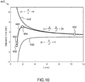
- a model 442 for quantifying the interactions of specific bio-particles as thrombin for example comprises a first curve 446, a second curve 448 and a third curve 450.
- the first curve 446 is a first model function that shows the evolution of the saturation time expressed in minute(s), as well as the total interaction force between two specific neighboring immobilized bio-particles, here thrombin molecules, versus the distance x, expressed in nm, separating the two specific neighboring immobilized bio-particles.
- the second curve 448 is a second model function that represents the contribution of the attractive force due to Coulomb interaction to the total interaction force between the two specific neighboring immobilized bio-particles, here thrombin molecules, versus the distance x, expressed in nm, separating the two specific neighboring immobilized bio-particles.
- the third curve 450 is a third model function that represents the contribution of the repulsive force due to Van-der-Waals interaction to the total interaction force between the two specific neighboring immobilized bio-particles, here thrombin molecules, versus the distance x, expressed in nm, separating the two specific neighboring immobilized bio-particles.
- the fitting parameters A, B and C are determined by fitting the first curve 446 with several measurements of saturation times corresponding to different concentrations of the bio-particles, here thrombin, immobilized to the sensor surface through the aptamer sandwich structure, and defining here four points 452, 454, 456, 458 of the first curve 446.
- the first, second, third points 452, 454, 456 illustrate the measured saturation times corresponding to the respective concentrations of thrombin equal to 86 pM, 0,86 nM and 8,6 nM.
- the fourth point 458 provides with a same value of the measured saturation time corresponding to the thrombin concentration.
- fitting parameters A, B and C are equal to 6, 8 and 3.
- the improvement of the minimum detection level of the magnetic measurement system 2, 302, 312 according to the invention has been measured and confirmed by experiments using streptavidin-biotin hybridization without embedding here a specific bio-particle in the sandwich aptamer structure.
- the voltage changes of the biosensor according to the invention caused by magnetic particles bound to the magnetic track 24 have been measured and compared by applying a constant magnetic field H1 or a constant magnetic field H 2.
- each sensor 12 was fabricated on Si/SiO 2 (1000 nm) substrates using a standard UV photolithography and lift-off methods.
- Sensor material is a tri-layer stack Ta/NiFe/Cu/IrMn/Ta (5/10/0.1/10/5 nm) fabricated using a DC magnetron sputtering (Seoul vacuum, Korea).
- the sensor shape is a cross-juntion of 50 ⁇ m ⁇ 50 ⁇ m.
- the lithography and lift-off processes are repeated the same for the fabrication of electrode Ta/Au (5/50 nm), passivation layer SiO 2 (200 nm) and activation layer Ta/Au (5/10 nm).
- the sensor was connected to a customized printed circuit board (PCB) using a wire bonding system (West Bond 7327C, USA) and packaged using UV epoxy with open active surface for measurement of magnetic particles.
- PCB printed circuit board
- Immobilization of the sensors surface with biotin was done with the following protocol. Especially, the sensor surface of SiO2 is modified by APTES (an aminosilane) and then functionalized with biotin.
- APTES an aminosilane
- magnetic nanoparticles are modified and functionalized with APTES and streptavidin.
- Streptavidin and biotin are to demonstrate the high resolution of the sensor because they have very strong bio affinity.
- the magnetic nanoparticles were then stored in a refrigerator at 4 - 8 degrees for later usage.
- the streptavidin functionalized magnetic particles were deposited on the sensor, to bind with the biotin, with concentrations of 1.5 fM, 3 fM, 15 fM, 150 fM and 1.5 nM.
- the voltage change induced by the magnetic particles was then measured for each concentration.
- the measurements showed that the voltage variation at H 2 is smaller than that at H 1 due to small Barkhausen noise.
- the S/N ratios measured at H 2 and H 1 are corresponding to 12.5 and 2.4, confirming the inventor's finding that higher sensitivity in detection of magnetic particles when the magnetic field applied is H 2 .
- the Figure 11 illustrates the voltage changes measured as a function of the concentration of magnetic particles, and the limits of detection (LOD) for two sets of experiments at two fields H 1 and H 2 .
- the voltage change resulting from the magnetic particles ( ⁇ V particles ) increases linearly with log scale of particle number.
- the high-accuracy of the fitting of 98 % shows that the measurement system and more specifically the magnetic sensor presents a high sensitivity and a good reproducibility for quantification of magnetic particles.
- LOD at applied field H 1 and H 2 are determined from linear fitting line to be as low as 2800 and 550 particles per micro-litter corresponding to 4.6 fM and 0.9 fM respectively.
- the LOD is calculated based on signal-to-noise approach, i.e., the signal is 3 times of standard deviation of the voltage variation recorded consecutively in 6 minutes without magnetic labels.
- the utilized sensors have similar magnetic sensitivity and surface modification process. The magnetic sensor exhibits feasibility in detection of ultra-low quantity of magnetic labels when the constant magnetic field applied is H 2 , down to one femto-Molar resolution.
- the detectable amount of the MR sensor is estimated to be 550 NPs (0.22 nanoparticle per ⁇ m 2 ) corresponding to the magnetic moment of 1.2 ⁇ 10 -13 emu measured in buffer solution.
- ⁇ V 5
- r 50 nm
- the inventors further used the highly sensitive magnetic sensor 12 to the detection of thrombin, one of the most important biomarkers in the blood.
- thrombin was sandwiched between two aptamers, a thiolated 15-mer DNA aptamer covalently bound to Au on the sensor surface (primary aptamer) and a biotinylated 15-mer DNA aptamer probe bound to the target thrombin with biotin (secondary aptamer).
- the voltage signals of the sensors were detected by means of a lock-in amplifier (RS830, Stanford research, USA) using first harmonic and 30 data points averaging setup.
- Measurement setup including electronics devices and sensor circuits are placed inside a homemade Faraday cage to minimize electrical noises of the measurement system.
- the Figure 12 illustrates real-time voltage measurements of different thrombin concentration modified on sensor surfaces in response to the same quantity of magnetic labels.
- Positive samples are the measurement of sensor with modified thrombin concentration from 8.6 ⁇ M to 86 pM with 10-fold dilution.
- Negative sample is the measurement of non modified sensor.
- Detection threshold of MR sensor is calculated by three times voltage signal of the non modified sensor with respect to the spot of magnetic labels (negative sample).
- LOD of thrombin concentration can be calculated from Figure 12 , where the changes of voltages ( ⁇ V MR ) are plotted with thrombin concentration. LOD of thrombin concentration is calculated by the interception of ⁇ V MR fitting line and LOD of voltage to be about 70 pM. The sensitivity of present MR sensor is thus proved to be superior in comparison with other measurement techniques.
- the inventors have investigated the variation of the detection threshold time with the thrombin concentration, which appeared to be a decreasing function of this concentration, as illustrated on the plot of Figure 13 .
- the measurement system according to the invention therefore opens up possible studies of phenomena which could not be investigated until now.
Landscapes
- Health & Medical Sciences (AREA)
- Immunology (AREA)
- Life Sciences & Earth Sciences (AREA)
- Chemical & Material Sciences (AREA)
- Engineering & Computer Science (AREA)
- Biomedical Technology (AREA)
- Urology & Nephrology (AREA)
- Molecular Biology (AREA)
- Hematology (AREA)
- Biochemistry (AREA)
- Analytical Chemistry (AREA)
- Physics & Mathematics (AREA)
- General Health & Medical Sciences (AREA)
- Pathology (AREA)
- General Physics & Mathematics (AREA)
- Cell Biology (AREA)
- Biotechnology (AREA)
- Microbiology (AREA)
- Food Science & Technology (AREA)
- Medicinal Chemistry (AREA)
- Chemical Kinetics & Catalysis (AREA)
- Electrochemistry (AREA)
- Investigating Or Analyzing Materials By The Use Of Magnetic Means (AREA)
Claims (16)
- Système de mesure magnétique permettant de mesurer une concentration de bio-particules spécifiques par le biais d'une détection sensible de marqueurs de particules magnétiques comprenant :- un capteur magnéto-résistif/magnéto-résistif Hall plan anisotrope hybride magnétique à base d'aptamère (AMR/PHR) (12) présentant :• une surface active (22) sur laquelle au moins une particule magnétique (28) est prête à être ou est étroitement liée à travers une structure aptamère de type sandwich (27) qui inclut une bio-particule unitaire capturée, la surface active incluant une piste magnétique (24) avec une forme de boucle fermée,• une première borne de courant (30) et une seconde borne (32), formant une paire de bornes de courant (30, 32) faisant face l'une à l'autre et en contact avec la piste magnétique à boucle fermée (24),• une première borne de tension (34) et une seconde borne de tension (36) formant une paire de bornes de tension faisant face l'une à l'autre et en contact avec la piste magnétique à boucle fermée (24),- une source de courant de polarisation électrique (14) configurée pour injecter un courant de polarisation dans la piste magnétique (24), la source électrique (14) étant raccordée entre la première et la seconde borne de courant (30, 32), et- un dispositif de mesure de tension (16) raccordé entre la première et la seconde borne de tension (34, 36) mesurant une tension différentielle VMR entre la paire de bornes de tension (34, 36),- un élément magnétique (18) permettant d'appliquer un champ magnétique constant DC effectif sur la piste magnétique à une amplitude prédéterminée ;- un dispositif de traitement de signal (20 ; 320) configuré pour déduire au moins une quantité physique sur la base de la tension différentielle et représentative de la concentration de bio-particules caractérisé en ce que le système de mesure magnétique est configuré pour choisir l'amplitude effective du champ magnétique constant DC appliqué afin qu'elle soit située à proximité (218, 210) d'une amplitude optimale du champ magnétique DC permanent compris dans un ensemble de deux valeurs optimales H1, H2 du champ magnétique constant DC, chaque valeur optimale H1, H2 optimisant localement la valeur absolue d'une première quantité


- Système de mesure magnétique selon la revendication 1, dans lequel :
le diamètre de la proximité (218, 210) entourant l'amplitude optimale H1 et H2, du champ magnétique DC permanent est inférieur à un premier seuil prédéterminé de sorte qu'un premier rapport entre la valeur absolue de la première quantité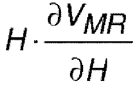

- Système de mesure selon l'une quelconque des revendications 1 à 2, dans lequel l'amplitude optimale locale H2 du champ magnétique DC permanent le plus proche de l'amplitude effective du champ magnétique constant DC appliqué est choisie parmi les deux amplitudes optimales H1, H2 de l'ensemble comme l'amplitude optimale locale qui maximise une seconde quantité


- Système de mesure selon l'une quelconque des revendications 1 à 3, dans lequel :
le diamètre de la proximité entourant l'amplitude optimale H1 ou H2 du champ magnétique DC permanent est inférieur à un second seuil prédéterminé de sorte qu'un second rapport entre la valeur absolue d'une seconde quantité


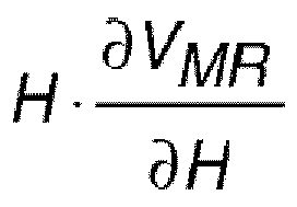

- Système de mesure magnétique selon l'une quelconque des revendications 1 à 4,
comprenant en outre une source magnétique de champ AC (314 ; 316) permettant d'appliquer un champ magnétique alternatif AC effectif sur la piste magnétique (24) à une amplitude prédéterminée et à une fréquence prédéterminée, le champ magnétique alternatif AC effectif appliqué étant colinéaire avec le champ magnétique DC constant effectif appliqué par l'élément magnétique (18). - Système de mesure magnétique selon la revendication 5, dans lequel la source magnétique de champ AC (314, 316) est
soit une source de champ magnétique externe incluant au moins une bobine (318) et une source de courant de bobine (317) permettant d'alimenter une source de courant AC,
soit une source de courant de polarisation AC électrique (334), configurée pour injecter un courant de polarisation AC alternatif dans la piste magnétique (24), la piste magnétique (24) générant en conséquence par auto-induction le champ AC appliqué. - Système de mesure magnétique selon l'une quelconque des revendications 1 à 6, dans lequel l'élément magnétique (18) est un ensemble comprenant au moins une bobine magnétique ou un aimant permanent.
- Système de mesure magnétique selon l'une quelconque des revendications 1 à 7, dans lequel la piste magnétique (24) est choisie dans le groupe constitué d'une piste croisée, d'une piste annulaire et d'une piste multi-anneaux.
- Système de mesure magnétique selon l'une quelconque des revendications 1 à 8, dans lequel la piste magnétique (24) est une piste annulaire, le nombre d'anneaux étant compris entre 1 et 17.
- Système de mesure magnétique selon la revendication 1 à 9, dans lequel la piste magnétique (24) est réalisée dans une structure choisie dans le groupe constitué d'une structure à trois couches incluant un film ferromagnétique, un film métallique et antiferromagnétique, en particulier Ta/NiFe/Cu/IrMn/Ta, une structure bicouches, en particulier Ta/NiFe/IrMn/Ta, et une vanne de spin, en particulier Ta/NiFe/Cu/NiFe/IrMn/Ta.
- Système de mesure magnétique selon l'une quelconque des revendications 1 à 10, dans lequel :le dispositif de traitement de signal (20 ; 320) comprend un processeur autonome (48) quand aucun champ magnétique AC n'est appliqué sur la piste magnétique (24), et comprend un processeur (48) et une unité d'enclenchement (326) quand un champ magnétique AC est appliqué sur la piste magnétique (24) ; etle dispositif de traitement de signal (320) est configuré pour extraire de la tension différentielle VMR la première ou seconde harmonique de la tension différentielle quand un champ magnétique AC est appliqué sur la piste magnétique (24) ; etle dispositif de traitement de signal (320) est configuré pour déterminer ladite au moins une quantité physique sur la base de ladite première ou seconde harmonique, quand la source de courant de polarisation électrique (14) injecte un courant de polarisation AC alternatif dans la piste magnétique (24) ou quand un champ magnétique AC extérieur est appliqué de manière colinéaire avec le champ magnétique DC constant extérieur.
- Procédé de mesure magnétique permettant de mesurer de faibles concentrations de bio-particules spécifiques contenues dans une solution donnée et/ou de quantifier les interactions de bio-particules spécifiques contenues dans une solution donnée, en particulier dans des solutions présentant des concentrations comprises entre des nanomoles et des picomoles,
le procédé de mesure magnétique comprenant les étapes consistant à :- fournir (404) un système de mesure magnétique (2) configuré pour mesurer une concentration de bio-particules à travers une détection sensible de marqueurs de particules magnétiques, le système de mesure magnétique (2) comprenant :- un capteur AMR/PHR hybride magnétique à base d'aptamère (12) incluant :• une surface préparée (22) sur laquelle au moins une particule magnétique (28) est prête à être ou est étroitement liée à travers une structure aptamère de type sandwich qui inclut une bio-particule unitaire capturée, la surface active incluant une piste magnétique (24) avec une forme en boucle fermée,• une première borne de courant (30) et une seconde borne (32), formant une paire de bornes de courant (30, 32) en face l'une de l'autre et en contact avec la piste magnétique à boucle fermée (24),• une première borne de tension (34) et une seconde borne de tension (36) formant une paire de bornes de tension l'une face à l'autre et en contact avec la piste magnétique à boucle fermée (24),- injecter (406) un courant de polarisation dans la piste magnétique (24) en utilisant la source électrique (14) qui est une source de courant de polarisation électrique (14) connectée entre la première et la seconde borne de courant (30, 32) ; et- appliquer (408) un champ magnétique constant DC effectif sur la piste magnétique (24) à une amplitude prédéterminée en utilisant un élément magnétique (18) ;- mesurer (410) une tension différentielle VMR entre la paire de bornes de tension (34, 36) en utilisant un dispositif de mesure de tension (16) raccordé entre la première et la seconde borne de tension (34, 36) ;- déterminer (412) au moins une quantité physique basée sur la tension différentielle et représentative de la concentration de bio-particules en utilisant un dispositif de traitement de signal (20) ;ledit procédé de mesure magnétique étant caractérisé en ce que :
l'amplitude effective du champ magnétique constant DC appliqué est étroitement située à proximité d'une amplitude optimale du champ magnétique DC permanent compris dans un ensemble de deux valeurs optimales H1, H2 du champ magnétique DC permanent, chaque valeur optimale H1, H2 maximisant localement la valeur absolue d'une première quantité

- Procédé de mesure magnétique selon la revendication 12, comprenant une étape (414) consistant à appliquer sur la surface active préparée une goutte d'une solution magnétique contenant des nanoparticules magnétiques revêtues de streptavidine qui est exécutée :soit avant l'étape consistant à fournir le système de mesure magnétique lors de la mesure de la concentration des bio-particules,soit après le début des étapes (406, 408) consistant à injecter un courant de polarisation dans la piste magnétique (24) et à appliquer un champ magnétique constant DC sur la piste magnétique et après le démarrage de l'étape (410) de mesure d'une tension différentielle VMR lors de la quantification des interactions des biomolécules spécifiques.
- Procédé de mesure magnétique selon l'une quelconque des revendications 12 à 13, dans lequel l'amplitude optimale locale H2 du champ magnétique DC permanent le plus proche de l'amplitude effective du champ magnétique constant DC appliqué est sélectionnée parmi les deux amplitudes optimales H1, H2 de l'ensemble comme l'amplitude optimale locale qui maximise une seconde quantité


- Procédé de mesure magnétique selon l'une quelconque des revendications 12 à 14, comprenant une étape (416) consistant à préparer la surface active (22) :- en modifiant la surface active avec un aptamère primaire marqué au thiol, puis- en appliquant une goutte d'une solution de bio-particules spécifiques à une concentration à déterminer à la surface immobilisée primaire, le volume de la goutte étant a priori connu, puis- en utilisant des aptamères secondaires marqués à la biotine pour se lier avec les bio-particules.
- Procédé de mesure magnétique selon l'une quelconque des revendications 12 à 15, permettant de quantifier les interactions de bio-particules spécifiques contenues dans une solution donnée comprenant une étape de traitement de signal supplémentaire (418) incluant les étapes consistant à :- déterminer (420) la cinétique de la liaison des particules magnétiques aux bio-particules spécifiques capturées et immobilisées sur la surface active à partir de l'évolution temporelle du signal magnétique mesuré ; puis- déterminer (422) un temps de saturation à partir de la cinétique de liaison des particules magnétiques ;- à partir du temps de saturation et d'une fonction de modèle, calculer une distance moyenne séparant les bio-particules dans leur solution et quantifier (424) les interactions de bio-particules spécifiques qui se répartissent dans une interaction de Coulomb à long terme et une interaction de Van de Waals à court terme.
Priority Applications (2)
| Application Number | Priority Date | Filing Date | Title |
|---|---|---|---|
| EP16305639.3A EP3252461B1 (fr) | 2016-06-02 | 2016-06-02 | Système de mesure magnétique ultrasensible basé sur un biocapteur planaire à effet hall (phr) et procédé pour mesurer de faibles concentrations de bioparticules spécifiques et quantifier des interactions de bio-particules |
| PCT/EP2017/063174 WO2017207640A1 (fr) | 2016-06-02 | 2017-05-31 | Système de mesure magnétique basé sur un biocapteur phr ultrasensible et procédé de mesure de faibles concentrations de bioparticules spécifiques et quantification d'interactions de bioparticules |
Applications Claiming Priority (1)
| Application Number | Priority Date | Filing Date | Title |
|---|---|---|---|
| EP16305639.3A EP3252461B1 (fr) | 2016-06-02 | 2016-06-02 | Système de mesure magnétique ultrasensible basé sur un biocapteur planaire à effet hall (phr) et procédé pour mesurer de faibles concentrations de bioparticules spécifiques et quantifier des interactions de bio-particules |
Publications (2)
| Publication Number | Publication Date |
|---|---|
| EP3252461A1 EP3252461A1 (fr) | 2017-12-06 |
| EP3252461B1 true EP3252461B1 (fr) | 2021-05-26 |
Family
ID=56292641
Family Applications (1)
| Application Number | Title | Priority Date | Filing Date |
|---|---|---|---|
| EP16305639.3A Active EP3252461B1 (fr) | 2016-06-02 | 2016-06-02 | Système de mesure magnétique ultrasensible basé sur un biocapteur planaire à effet hall (phr) et procédé pour mesurer de faibles concentrations de bioparticules spécifiques et quantifier des interactions de bio-particules |
Country Status (2)
| Country | Link |
|---|---|
| EP (1) | EP3252461B1 (fr) |
| WO (1) | WO2017207640A1 (fr) |
Families Citing this family (6)
| Publication number | Priority date | Publication date | Assignee | Title |
|---|---|---|---|---|
| CN109541014B (zh) * | 2018-12-26 | 2022-09-06 | 河南工业大学 | 一种基于磁信号的磁性纳米粒子质量检测方法 |
| CN110967396B (zh) * | 2019-12-16 | 2023-01-06 | 内蒙古工业大学 | 基于磁珠浓度和模拟病变体形状的巨磁阻抗效应生物磁测装置 |
| CN113219170B (zh) * | 2021-04-27 | 2022-02-01 | 成都云芯医联科技有限公司 | 磁免疫检测系统及使用方法 |
| US20220404347A1 (en) * | 2021-06-17 | 2022-12-22 | Roche Diagnostics Operations, Inc. | Methods for detecting an analyte using structure switching binding agents |
| EP4416518A1 (fr) | 2021-10-11 | 2024-08-21 | Institut National De La Sante Et De La Recherche Medicale (Inserm) | Dispositifs et systèmes de mesure de champs magnétiques |
| CN115963038B (zh) * | 2022-12-14 | 2023-07-28 | 中国科学院空间应用工程与技术中心 | 基于空间微重力条件的磁性颗粒运动轨迹测量系统及方法 |
Family Cites Families (1)
| Publication number | Priority date | Publication date | Assignee | Title |
|---|---|---|---|---|
| EP2685273A1 (fr) * | 2012-07-13 | 2014-01-15 | Université Montpellier 2, Sciences et Techniques | Système et procédé de détection micromagnétometrique permettant de détecter des signatures magnétiques de matériaux magnétiques |
-
2016
- 2016-06-02 EP EP16305639.3A patent/EP3252461B1/fr active Active
-
2017
- 2017-05-31 WO PCT/EP2017/063174 patent/WO2017207640A1/fr not_active Ceased
Non-Patent Citations (1)
| Title |
|---|
| None * |
Also Published As
| Publication number | Publication date |
|---|---|
| EP3252461A1 (fr) | 2017-12-06 |
| WO2017207640A1 (fr) | 2017-12-07 |
Similar Documents
| Publication | Publication Date | Title |
|---|---|---|
| EP3252461B1 (fr) | Système de mesure magnétique ultrasensible basé sur un biocapteur planaire à effet hall (phr) et procédé pour mesurer de faibles concentrations de bioparticules spécifiques et quantifier des interactions de bio-particules | |
| EP1456658B1 (fr) | Capteur et procede pour mesurer la densite locale des nanoparticules magnetiques dans un micro-reseau | |
| Li et al. | Spin valve sensors for ultrasensitive detection of superparamagnetic nanoparticles for biological applications | |
| CN101632018B (zh) | 用于感测磁性粒子的传感器设备和方法 | |
| Sinha et al. | Planar Hall magnetoresistive aptasensor for thrombin detection | |
| CN1829922B (zh) | 具有改进信噪比的芯片内磁性粒子传感器 | |
| US20100188075A1 (en) | Nanomagnetic detector array for biomolecular recognition | |
| JP2008522150A (ja) | バイオセンサにおける磁気クロストークを低減する手段及び方法 | |
| US9551687B2 (en) | High magnetic moment particle detection | |
| CN101517394A (zh) | 用于感测粒子的传感器装置和方法 | |
| JP4731927B2 (ja) | 磁性体センサおよび検出キット | |
| Feng et al. | An integrated magnetic microfluidic chip for rapid immunodetection of the prostate specific antigen using immunomagnetic beads | |
| JP4756868B2 (ja) | 検出方法 | |
| EP2488866A2 (fr) | Système d'amplifcation pour elisa utilisant la détection du movement d'une particule magnetique | |
| CN101443674A (zh) | 用于激励磁阻传感器的系统和方法 | |
| US9733315B2 (en) | Nanomagnetic detector array for biomolecular recognition | |
| Su et al. | GMR biosensing with magnetic nanowires as labels for the detection of osteosarcoma cells | |
| Lagae et al. | Magnetic biosensors for genetic screening of cystic fibrosis | |
| Freitas et al. | Magnetoresistive DNA chips | |
| Kim et al. | An InSb-based magnetoresistive biosensor using Fe3O4 nanoparticles | |
| US20230273199A1 (en) | Single-molecule, real-time, label-free dynamic biosensing with nanoscale magnetic field sensors | |
| Ahmadi et al. | Application of magnetic nanomaterials in magnetic field sensors | |
| Albisetti et al. | Optimization of the bio-functionalized area of magnetic biosensors | |
| Udaya et al. | Magnetic biosensors: Need and progress | |
| Udaya et al. | Magnetic biosensors |
Legal Events
| Date | Code | Title | Description |
|---|---|---|---|
| PUAI | Public reference made under article 153(3) epc to a published international application that has entered the european phase |
Free format text: ORIGINAL CODE: 0009012 |
|
| STAA | Information on the status of an ep patent application or granted ep patent |
Free format text: STATUS: THE APPLICATION HAS BEEN PUBLISHED |
|
| AK | Designated contracting states |
Kind code of ref document: A1 Designated state(s): AL AT BE BG CH CY CZ DE DK EE ES FI FR GB GR HR HU IE IS IT LI LT LU LV MC MK MT NL NO PL PT RO RS SE SI SK SM TR |
|
| AX | Request for extension of the european patent |
Extension state: BA ME |
|
| STAA | Information on the status of an ep patent application or granted ep patent |
Free format text: STATUS: REQUEST FOR EXAMINATION WAS MADE |
|
| 17P | Request for examination filed |
Effective date: 20180323 |
|
| RBV | Designated contracting states (corrected) |
Designated state(s): AL AT BE BG CH CY CZ DE DK EE ES FI FR GB GR HR HU IE IS IT LI LT LU LV MC MK MT NL NO PL PT RO RS SE SI SK SM TR |
|
| GRAP | Despatch of communication of intention to grant a patent |
Free format text: ORIGINAL CODE: EPIDOSNIGR1 |
|
| STAA | Information on the status of an ep patent application or granted ep patent |
Free format text: STATUS: GRANT OF PATENT IS INTENDED |
|
| INTG | Intention to grant announced |
Effective date: 20201222 |
|
| GRAS | Grant fee paid |
Free format text: ORIGINAL CODE: EPIDOSNIGR3 |
|
| GRAA | (expected) grant |
Free format text: ORIGINAL CODE: 0009210 |
|
| STAA | Information on the status of an ep patent application or granted ep patent |
Free format text: STATUS: THE PATENT HAS BEEN GRANTED |
|
| AK | Designated contracting states |
Kind code of ref document: B1 Designated state(s): AL AT BE BG CH CY CZ DE DK EE ES FI FR GB GR HR HU IE IS IT LI LT LU LV MC MK MT NL NO PL PT RO RS SE SI SK SM TR |
|
| REG | Reference to a national code |
Ref country code: GB Ref legal event code: FG4D |
|
| REG | Reference to a national code |
Ref country code: CH Ref legal event code: EP |
|
| REG | Reference to a national code |
Ref country code: AT Ref legal event code: REF Ref document number: 1396729 Country of ref document: AT Kind code of ref document: T Effective date: 20210615 |
|
| REG | Reference to a national code |
Ref country code: DE Ref legal event code: R096 Ref document number: 602016058349 Country of ref document: DE |
|
| REG | Reference to a national code |
Ref country code: IE Ref legal event code: FG4D |
|
| REG | Reference to a national code |
Ref country code: LT Ref legal event code: MG9D |
|
| REG | Reference to a national code |
Ref country code: AT Ref legal event code: MK05 Ref document number: 1396729 Country of ref document: AT Kind code of ref document: T Effective date: 20210526 |
|
| PG25 | Lapsed in a contracting state [announced via postgrant information from national office to epo] |
Ref country code: FI Free format text: LAPSE BECAUSE OF FAILURE TO SUBMIT A TRANSLATION OF THE DESCRIPTION OR TO PAY THE FEE WITHIN THE PRESCRIBED TIME-LIMIT Effective date: 20210526 Ref country code: LT Free format text: LAPSE BECAUSE OF FAILURE TO SUBMIT A TRANSLATION OF THE DESCRIPTION OR TO PAY THE FEE WITHIN THE PRESCRIBED TIME-LIMIT Effective date: 20210526 Ref country code: HR Free format text: LAPSE BECAUSE OF FAILURE TO SUBMIT A TRANSLATION OF THE DESCRIPTION OR TO PAY THE FEE WITHIN THE PRESCRIBED TIME-LIMIT Effective date: 20210526 Ref country code: BG Free format text: LAPSE BECAUSE OF FAILURE TO SUBMIT A TRANSLATION OF THE DESCRIPTION OR TO PAY THE FEE WITHIN THE PRESCRIBED TIME-LIMIT Effective date: 20210826 Ref country code: AT Free format text: LAPSE BECAUSE OF FAILURE TO SUBMIT A TRANSLATION OF THE DESCRIPTION OR TO PAY THE FEE WITHIN THE PRESCRIBED TIME-LIMIT Effective date: 20210526 |
|
| REG | Reference to a national code |
Ref country code: NL Ref legal event code: MP Effective date: 20210526 |
|
| PG25 | Lapsed in a contracting state [announced via postgrant information from national office to epo] |
Ref country code: LV Free format text: LAPSE BECAUSE OF FAILURE TO SUBMIT A TRANSLATION OF THE DESCRIPTION OR TO PAY THE FEE WITHIN THE PRESCRIBED TIME-LIMIT Effective date: 20210526 Ref country code: GR Free format text: LAPSE BECAUSE OF FAILURE TO SUBMIT A TRANSLATION OF THE DESCRIPTION OR TO PAY THE FEE WITHIN THE PRESCRIBED TIME-LIMIT Effective date: 20210827 Ref country code: IS Free format text: LAPSE BECAUSE OF FAILURE TO SUBMIT A TRANSLATION OF THE DESCRIPTION OR TO PAY THE FEE WITHIN THE PRESCRIBED TIME-LIMIT Effective date: 20210926 Ref country code: NO Free format text: LAPSE BECAUSE OF FAILURE TO SUBMIT A TRANSLATION OF THE DESCRIPTION OR TO PAY THE FEE WITHIN THE PRESCRIBED TIME-LIMIT Effective date: 20210826 Ref country code: PT Free format text: LAPSE BECAUSE OF FAILURE TO SUBMIT A TRANSLATION OF THE DESCRIPTION OR TO PAY THE FEE WITHIN THE PRESCRIBED TIME-LIMIT Effective date: 20210927 Ref country code: PL Free format text: LAPSE BECAUSE OF FAILURE TO SUBMIT A TRANSLATION OF THE DESCRIPTION OR TO PAY THE FEE WITHIN THE PRESCRIBED TIME-LIMIT Effective date: 20210526 Ref country code: RS Free format text: LAPSE BECAUSE OF FAILURE TO SUBMIT A TRANSLATION OF THE DESCRIPTION OR TO PAY THE FEE WITHIN THE PRESCRIBED TIME-LIMIT Effective date: 20210526 Ref country code: SE Free format text: LAPSE BECAUSE OF FAILURE TO SUBMIT A TRANSLATION OF THE DESCRIPTION OR TO PAY THE FEE WITHIN THE PRESCRIBED TIME-LIMIT Effective date: 20210526 |
|
| PG25 | Lapsed in a contracting state [announced via postgrant information from national office to epo] |
Ref country code: NL Free format text: LAPSE BECAUSE OF FAILURE TO SUBMIT A TRANSLATION OF THE DESCRIPTION OR TO PAY THE FEE WITHIN THE PRESCRIBED TIME-LIMIT Effective date: 20210526 |
|
| REG | Reference to a national code |
Ref country code: DE Ref legal event code: R119 Ref document number: 602016058349 Country of ref document: DE |
|
| PG25 | Lapsed in a contracting state [announced via postgrant information from national office to epo] |
Ref country code: CZ Free format text: LAPSE BECAUSE OF FAILURE TO SUBMIT A TRANSLATION OF THE DESCRIPTION OR TO PAY THE FEE WITHIN THE PRESCRIBED TIME-LIMIT Effective date: 20210526 Ref country code: EE Free format text: LAPSE BECAUSE OF FAILURE TO SUBMIT A TRANSLATION OF THE DESCRIPTION OR TO PAY THE FEE WITHIN THE PRESCRIBED TIME-LIMIT Effective date: 20210526 Ref country code: DK Free format text: LAPSE BECAUSE OF FAILURE TO SUBMIT A TRANSLATION OF THE DESCRIPTION OR TO PAY THE FEE WITHIN THE PRESCRIBED TIME-LIMIT Effective date: 20210526 Ref country code: SM Free format text: LAPSE BECAUSE OF FAILURE TO SUBMIT A TRANSLATION OF THE DESCRIPTION OR TO PAY THE FEE WITHIN THE PRESCRIBED TIME-LIMIT Effective date: 20210526 Ref country code: SK Free format text: LAPSE BECAUSE OF FAILURE TO SUBMIT A TRANSLATION OF THE DESCRIPTION OR TO PAY THE FEE WITHIN THE PRESCRIBED TIME-LIMIT Effective date: 20210526 Ref country code: RO Free format text: LAPSE BECAUSE OF FAILURE TO SUBMIT A TRANSLATION OF THE DESCRIPTION OR TO PAY THE FEE WITHIN THE PRESCRIBED TIME-LIMIT Effective date: 20210526 Ref country code: ES Free format text: LAPSE BECAUSE OF FAILURE TO SUBMIT A TRANSLATION OF THE DESCRIPTION OR TO PAY THE FEE WITHIN THE PRESCRIBED TIME-LIMIT Effective date: 20210526 |
|
| REG | Reference to a national code |
Ref country code: CH Ref legal event code: PL |
|
| REG | Reference to a national code |
Ref country code: BE Ref legal event code: MM Effective date: 20210630 |
|
| PLBE | No opposition filed within time limit |
Free format text: ORIGINAL CODE: 0009261 |
|
| STAA | Information on the status of an ep patent application or granted ep patent |
Free format text: STATUS: NO OPPOSITION FILED WITHIN TIME LIMIT |
|
| PG25 | Lapsed in a contracting state [announced via postgrant information from national office to epo] |
Ref country code: MC Free format text: LAPSE BECAUSE OF FAILURE TO SUBMIT A TRANSLATION OF THE DESCRIPTION OR TO PAY THE FEE WITHIN THE PRESCRIBED TIME-LIMIT Effective date: 20210526 Ref country code: LU Free format text: LAPSE BECAUSE OF NON-PAYMENT OF DUE FEES Effective date: 20210602 |
|
| GBPC | Gb: european patent ceased through non-payment of renewal fee |
Effective date: 20210826 |
|
| PG25 | Lapsed in a contracting state [announced via postgrant information from national office to epo] |
Ref country code: LI Free format text: LAPSE BECAUSE OF NON-PAYMENT OF DUE FEES Effective date: 20210630 Ref country code: IE Free format text: LAPSE BECAUSE OF NON-PAYMENT OF DUE FEES Effective date: 20210602 Ref country code: DE Free format text: LAPSE BECAUSE OF NON-PAYMENT OF DUE FEES Effective date: 20220101 Ref country code: CH Free format text: LAPSE BECAUSE OF NON-PAYMENT OF DUE FEES Effective date: 20210630 |
|
| 26N | No opposition filed |
Effective date: 20220301 |
|
| PG25 | Lapsed in a contracting state [announced via postgrant information from national office to epo] |
Ref country code: IS Free format text: LAPSE BECAUSE OF FAILURE TO SUBMIT A TRANSLATION OF THE DESCRIPTION OR TO PAY THE FEE WITHIN THE PRESCRIBED TIME-LIMIT Effective date: 20210926 Ref country code: AL Free format text: LAPSE BECAUSE OF FAILURE TO SUBMIT A TRANSLATION OF THE DESCRIPTION OR TO PAY THE FEE WITHIN THE PRESCRIBED TIME-LIMIT Effective date: 20210526 |
|
| PG25 | Lapsed in a contracting state [announced via postgrant information from national office to epo] |
Ref country code: IT Free format text: LAPSE BECAUSE OF FAILURE TO SUBMIT A TRANSLATION OF THE DESCRIPTION OR TO PAY THE FEE WITHIN THE PRESCRIBED TIME-LIMIT Effective date: 20210526 Ref country code: GB Free format text: LAPSE BECAUSE OF NON-PAYMENT OF DUE FEES Effective date: 20210826 Ref country code: BE Free format text: LAPSE BECAUSE OF NON-PAYMENT OF DUE FEES Effective date: 20210630 |
|
| PG25 | Lapsed in a contracting state [announced via postgrant information from national office to epo] |
Ref country code: HU Free format text: LAPSE BECAUSE OF FAILURE TO SUBMIT A TRANSLATION OF THE DESCRIPTION OR TO PAY THE FEE WITHIN THE PRESCRIBED TIME-LIMIT; INVALID AB INITIO Effective date: 20160602 |
|
| PG25 | Lapsed in a contracting state [announced via postgrant information from national office to epo] |
Ref country code: CY Free format text: LAPSE BECAUSE OF FAILURE TO SUBMIT A TRANSLATION OF THE DESCRIPTION OR TO PAY THE FEE WITHIN THE PRESCRIBED TIME-LIMIT Effective date: 20210526 |
|
| PG25 | Lapsed in a contracting state [announced via postgrant information from national office to epo] |
Ref country code: MK Free format text: LAPSE BECAUSE OF FAILURE TO SUBMIT A TRANSLATION OF THE DESCRIPTION OR TO PAY THE FEE WITHIN THE PRESCRIBED TIME-LIMIT Effective date: 20210526 |
|
| PG25 | Lapsed in a contracting state [announced via postgrant information from national office to epo] |
Ref country code: MT Free format text: LAPSE BECAUSE OF FAILURE TO SUBMIT A TRANSLATION OF THE DESCRIPTION OR TO PAY THE FEE WITHIN THE PRESCRIBED TIME-LIMIT Effective date: 20210526 |
|
| PGFP | Annual fee paid to national office [announced via postgrant information from national office to epo] |
Ref country code: FR Payment date: 20250523 Year of fee payment: 10 |
|
| PG25 | Lapsed in a contracting state [announced via postgrant information from national office to epo] |
Ref country code: TR Free format text: LAPSE BECAUSE OF FAILURE TO SUBMIT A TRANSLATION OF THE DESCRIPTION OR TO PAY THE FEE WITHIN THE PRESCRIBED TIME-LIMIT Effective date: 20210526 |