EP3252902A1 - Unité de détection d'arc électrique parasite - Google Patents
Unité de détection d'arc électrique parasite Download PDFInfo
- Publication number
- EP3252902A1 EP3252902A1 EP17171304.3A EP17171304A EP3252902A1 EP 3252902 A1 EP3252902 A1 EP 3252902A1 EP 17171304 A EP17171304 A EP 17171304A EP 3252902 A1 EP3252902 A1 EP 3252902A1
- Authority
- EP
- European Patent Office
- Prior art keywords
- product
- value
- current
- time
- voltage
- Prior art date
- Legal status (The legal status is an assumption and is not a legal conclusion. Google has not performed a legal analysis and makes no representation as to the accuracy of the status listed.)
- Withdrawn
Links
Images


Classifications
-
- G—PHYSICS
- G01—MEASURING; TESTING
- G01R—MEASURING ELECTRIC VARIABLES; MEASURING MAGNETIC VARIABLES
- G01R31/00—Arrangements for testing electric properties; Arrangements for locating electric faults; Arrangements for electrical testing characterised by what is being tested not provided for elsewhere
- G01R31/12—Testing dielectric strength or breakdown voltage ; Testing or monitoring effectiveness or level of insulation, e.g. of a cable or of an apparatus, for example using partial discharge measurements; Electrostatic testing
- G01R31/14—Circuits therefor, e.g. for generating test voltages, sensing circuits
-
- H—ELECTRICITY
- H02—GENERATION; CONVERSION OR DISTRIBUTION OF ELECTRIC POWER
- H02H—EMERGENCY PROTECTIVE CIRCUIT ARRANGEMENTS
- H02H1/00—Details of emergency protective circuit arrangements
- H02H1/0007—Details of emergency protective circuit arrangements concerning the detecting means
- H02H1/0015—Using arc detectors
-
- G—PHYSICS
- G01—MEASURING; TESTING
- G01R—MEASURING ELECTRIC VARIABLES; MEASURING MAGNETIC VARIABLES
- G01R19/00—Arrangements for measuring currents or voltages or for indicating presence or sign thereof
- G01R19/165—Indicating that current or voltage is either above or below a predetermined value or within or outside a predetermined range of values
-
- G—PHYSICS
- G01—MEASURING; TESTING
- G01R—MEASURING ELECTRIC VARIABLES; MEASURING MAGNETIC VARIABLES
- G01R31/00—Arrangements for testing electric properties; Arrangements for locating electric faults; Arrangements for electrical testing characterised by what is being tested not provided for elsewhere
- G01R31/50—Testing of electric apparatus, lines, cables or components for short-circuits, continuity, leakage current or incorrect line connections
- G01R31/52—Testing for short-circuits, leakage current or ground faults
-
- H—ELECTRICITY
- H02—GENERATION; CONVERSION OR DISTRIBUTION OF ELECTRIC POWER
- H02H—EMERGENCY PROTECTIVE CIRCUIT ARRANGEMENTS
- H02H3/00—Emergency protective circuit arrangements for automatic disconnection directly responsive to an undesired change from normal electric working condition with or without subsequent reconnection ; integrated protection
- H02H3/16—Emergency protective circuit arrangements for automatic disconnection directly responsive to an undesired change from normal electric working condition with or without subsequent reconnection ; integrated protection responsive to fault current to earth, frame or mass
-
- H—ELECTRICITY
- H02—GENERATION; CONVERSION OR DISTRIBUTION OF ELECTRIC POWER
- H02H—EMERGENCY PROTECTIVE CIRCUIT ARRANGEMENTS
- H02H3/00—Emergency protective circuit arrangements for automatic disconnection directly responsive to an undesired change from normal electric working condition with or without subsequent reconnection ; integrated protection
- H02H3/38—Emergency protective circuit arrangements for automatic disconnection directly responsive to an undesired change from normal electric working condition with or without subsequent reconnection ; integrated protection responsive to both voltage and current; responsive to phase angle between voltage and current
-
- G—PHYSICS
- G01—MEASURING; TESTING
- G01R—MEASURING ELECTRIC VARIABLES; MEASURING MAGNETIC VARIABLES
- G01R31/00—Arrangements for testing electric properties; Arrangements for locating electric faults; Arrangements for electrical testing characterised by what is being tested not provided for elsewhere
- G01R31/12—Testing dielectric strength or breakdown voltage ; Testing or monitoring effectiveness or level of insulation, e.g. of a cable or of an apparatus, for example using partial discharge measurements; Electrostatic testing
- G01R31/1227—Testing dielectric strength or breakdown voltage ; Testing or monitoring effectiveness or level of insulation, e.g. of a cable or of an apparatus, for example using partial discharge measurements; Electrostatic testing of components, parts or materials
- G01R31/1263—Testing dielectric strength or breakdown voltage ; Testing or monitoring effectiveness or level of insulation, e.g. of a cable or of an apparatus, for example using partial discharge measurements; Electrostatic testing of components, parts or materials of solid or fluid materials, e.g. insulation films, bulk material; of semiconductors or LV electronic components or parts; of cable, line or wire insulation
- G01R31/1272—Testing dielectric strength or breakdown voltage ; Testing or monitoring effectiveness or level of insulation, e.g. of a cable or of an apparatus, for example using partial discharge measurements; Electrostatic testing of components, parts or materials of solid or fluid materials, e.g. insulation films, bulk material; of semiconductors or LV electronic components or parts; of cable, line or wire insulation of cable, line or wire insulation, e.g. using partial discharge measurements
Definitions
- the invention relates to an arc fault detection unit, a circuit breaker, a short-circuiter and a method for arc fault detection.
- low-voltage circuits or low-voltage systems respectively low-voltage networks, i. Circuits for voltages up to 1000 volts AC or 1500 volts DC, short circuits are usually associated with arcing faults occurring, such as parallel or serial arcs. Particularly in high-performance distribution and switchgear installations, these can lead to disastrous destruction of equipment, plant components or complete switchgear if the shutdown is not sufficiently fast. In order to avoid a prolonged and large-scale failure of the power supply and to reduce personal injury, it is necessary such arcs, especially high-current or parallel arcs, to detect and delete in a few milliseconds. Conventional power system protection systems (e.g., fuses and circuit breakers) can not provide reliable protection under the required timing requirements.
- Conventional power system protection systems e.g., fuses and circuit breakers
- Circuit breaker here are meant in particular switch for low voltage.
- Circuit breakers are used, in particular in low-voltage systems, usually for currents of 63 to 6300 amperes. More specifically, closed circuit breakers, such as molded case circuit breakers, are used for currents of 63 to 1600 amperes, more particularly 125 to 630 or 1200 amperes. Open circuit breakers or air circuit breakers, such as Air Circuit Breaker, are used in particular for currents of 630 to 6300 amperes, more particularly of 1200 to 6300 amps.
- Circuit breakers according to the invention may in particular an electronic trip unit, also referred to as Electronic Trip Unit, short ETU, have.
- ETU Electronic Trip Unit
- Circuit breakers monitor the current flowing through them and interrupt the electrical current to an energy sink, or consumer, which is referred to as tripping when current limit values or current-time-out limits, i. if a current value exists for a certain period of time, be exceeded.
- the determination of tripping conditions and the tripping of a circuit breaker can be carried out by means of an electronic tripping unit.
- Short-circuiters are special devices for short-circuiting cables or busbars in order to produce defined short circuits for the protection of circuits or systems.
- Conventional arc fault detection systems evaluate the light emission generated by the arc and hereby detect the arc fault.
- optical waveguides or optical detection systems must be routed parallel to the electrical lines or busbars in order to detect any arcing faults that may occur.
- Object of the present invention is to show a way to detect arcing.
- an arc fault detection unit for a low-voltage electrical circuit at least one voltage sensor associated with the circuit, for the periodic determination of electrical voltage values (um) of the circuit, at least one current sensor associated with the circuit, for the periodic determination of electrical current values of the circuit, which are both connected to an evaluation unit, and which are configured in such a way in that pairs of values comprising a voltage value and a current quantity are continuously determined.
- a set of values comprises a plurality of pairs of values, and at least two sets of values are used to calculate an arc voltage which is compared with a first threshold value and, if this amount is exceeded, an arc detection signal is output.
- amount exceeding is meant exceeding, which could be below in terms of a positive first threshold of exceeding and / or a negative fourth threshold, analogous to a magnitude comparison of the arc voltage with a (positive) threshold, which of course can also be done.
- the sensors can be arranged externally and need not be arranged in the housing of the fault arc detection unit.
- the periodic or continuous determination of pairs of values of a voltage value and a current variable, in particular at a time, can be done for example by scanning the corresponding values. This has the particular advantage that a simple and secure way to detect arcing is given.
- the calculation of the arc voltage from three sets of values. This has the particular advantage that a particularly accurate determination of the arc voltage is made possible, so as to detect safe arc fault.
- the electric current quantity is either an electric current value (im) or a value for the change of the electric current after time (i ' m ).
- a Rogowski coil can advantageously be used to determine the current magnitude, whereby the change in the current over time is detected.
- a value pair thus advantageously has a voltage value (u m ), a current value (i m ) and a value for the change of the current after time (i ' m ), with which the arc voltage (U lb ) can be calculated.
- the three values of a value pair can also be determined, sampled or measured in parallel.
- the evaluation unit is designed such that the calculation of the arc voltage (U lb ) is performed by means of an integral equation or its solution. This has the particular advantage that a comprehensive calculation option is available taking into account many parameters of a real circuit.
- the evaluation unit is designed such that a value pair is assigned to only one set of values. This has the particular advantage that a particularly accurate calculation is made possible because redundancies of the determined Value pairs in different value sets are excluded.
- the evaluation unit is designed such that each value set has a fixed number of value pairs. This has the particular advantage that there is a simple possibility for the cyclical calculation of the arc voltage, since the same number of value pairs can be evaluated in each pass.
- the evaluation unit is configured such that the value pairs are continuously assigned to a value set until the fixed number of value pairs is reached, and the subsequent value pairs are assigned to the next value set.
- the evaluation unit is designed such that the electrical voltage values and / or current values are determined at a fixed time interval (dt). This in turn has the particular advantage that a particularly accurate determination of the arc voltage or an arc fault is possible.
- the evaluation unit is configured such that a sign value of the current value assumes the value zero if the magnitude of the voltage value of this value pair falls below a second threshold value. That is, the result of the sign function or signum function is always set to zero if the magnitude of the simultaneous voltage value is less than or equal to the second threshold value.
- a sign value of the current value assumes the value zero if the magnitude of the voltage value of this value pair falls below a second threshold value. That is, the result of the sign function or signum function is always set to zero if the magnitude of the simultaneous voltage value is less than or equal to the second threshold value.
- an anode-cathode voltage drop of about 20 V can be assumed as a typical threshold value since it can be assumed that no arc can arise below this second threshold value.
- the evaluation unit is designed such that the arc voltage (Ulb) is a quotient whose dividend has the seventh difference (D7) and whose divisor has the eighth difference (D8). This has the particular advantage that a very accurate determination of an arc fault voltage is made possible.
- the evaluation unit is designed such that the arc voltage (Ulb) is set to the value zero when the sum of the first (ss1), second (ss2) and third (ss3) time-sign product is equal to zero is.
- This has the special advantage that impermissible calculation results in the calculation of the arc voltage be avoided. These can occur when the three time sign products (ss1, ss2, ss3) are each zero. In this case, the arc voltage is set to zero.
- a circuit breaker for a low-voltage electrical circuit is further provided.
- This has an inventive arc fault detection unit.
- This is connected to the power switch, which are designed such that upon delivery of an arc fault detection signal, the circuit breaker triggers, i. breaks the electrical circuit.
- the circuit breaker triggers, i. breaks the electrical circuit.
- a cancellation of the arc fault can be achieved.
- the circuit breaker has an electronic trip unit, a very rapid tripping of the circuit breaker can be achieved in the presence of an arcing fault detection signal.
- This has the particular advantage that a circuit breaker is extended by a further, advantageous functionality for the protection of electrical systems.
- the detection and shutdown of arcs takes place advantageously in a device.
- existing assemblies such as voltage and / or current sensors, power supply, microprocessors for the evaluation, etc. co-use and thus achieve synergies.
- a short-circuiter comprising an arc fault detection unit which is connected to the short-circuiter.
- These are designed such that upon delivery of an arc fault detection signal of Short circuiter short circuits the electrical circuit to cause erasure of the arc.
- a method for detecting arcing for an electrical circuit, in particular a low-voltage circuit.
- electrical voltage values and current variables of the electric circuit are periodically determined so that there are continuously pairs of values, including a voltage value and a current value.
- a value set comprises several value pairs. From (at least) two sets of values, an arc voltage is calculated which is compared with a first threshold value and, when exceeded, an arc fault detection signal is emitted.
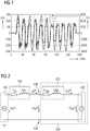
- FIG. 1 shows a representation of a diagram in which the time profile of the electrical voltage U and the electric current I after ignition of an arc or arc fault, in particular parallel arc fault, in an electrical circuit, in particular low-voltage circuit is shown.
- the time t is shown in milliseconds (ms) on the horizontal X-axis.
- the size of the electrical voltage U in volts (V) is shown on the vertical Y-axis on the left scale.
- the right scale shows the magnitude of the electric current I in amperes (A).
- electrical voltage values u m and electrical current values i m are determined, for example with one sensor each.
- the electric current i m can be measured directly.
- the change in the current after the time i ' m can be measured.
- the change in the current after time i ' m can be determined therefrom, for example by differentiation of the current value i m .
- the electric current i m can be determined therefrom, for example by integration of the change in the electric current after the time i' m .
- the measurement of the change of the electric current after the time i ' m can be done for example with a Rogowski coil.
- the integration is particularly easy to implement, since the integral of the sine is a cosine and of the cosine a sine wave.
- the current value i m and the change in the current after the time i ' m can also be measured in parallel, eg with 2 sensors. This eliminates the need for a conversion.
- a time interval for example a fixed time interval dt
- voltage values u m and current values i m or voltage values u m and values for the change in the electrical current after time i ' m are repeatedly determined.
- the determination can be made by sampling the values.
- the sampling frequency or measuring frequency should be a multiple of the frequency of the measured alternating variables.
- the measuring frequency could be in the kilohertz range, for example between 1 and 200 kHz, more specifically at 10 to 60 or 100 kHz, in particular in the range 40-50 kHz.
- a voltage value and a current value are respectively determined at one, in particular the same, instant.
- two values of the current value such as the current value and the change in the current value after the time, can also be determined in parallel.
- FIG. 12 shows an equivalent circuit diagram of an electrical circuit including an electrical energy source 100 providing a grid voltage u n (t), a grid connected thereto, and a feeder cable 200 represented by spare electrical circuit elements such as a feed cable Resistor R ek and a feed cable inductor or coil L ek , which is an electrical load,
- Operating means or energy sink 300 follows, again represented by electrical equivalent switching elements, such as a load resistor R BM and a load inductance or coil L BM .
- feed cable 200 and load 300 can be an electrical voltage u m (t) and an electric current magnitude, such as the electric current value i m (t) or / and the change of the current after the time i ' m (t), respectively first derivative of the current after the time to be measured.
- These quantities are detected at the measuring points 600 in order to be further processed in the fault arc detection unit.
- the area monitored for arc fault is shown by a dashed line 500.
- an arc can occur, which is represented by an arc 400 with an arc voltage U lb (t).
- an arc voltage U lb in the fault arc detection unit is continuously calculated with the aid of the measured / sampled voltage u m (t) and the measured / sampled current variable (current or / and current change).
- the voltage, the current and the change in the current over time are used for the calculation.
- a value pair is assigned to at least one value set.
- a value pair is assigned to exactly one value set. It is essential that a set of values contains at least one value pair that is not contained in the preceding or following value set.
- an arc voltage is calculated from at least two sets of values.
- a fixed number of value pairs which are determined, for example, temporally successively, for example with a fixed time interval, assigned to a set of values.
- a set of values 10 value pairs.
- the first 10 value pairs are assigned to the first value set.
- the second 10 value pairs are assigned to the second value set, the third 10 value pairs to the third value set, etc.
- At least 2 sets of values are used for the determination of an arc voltage or an arc fault.
- the calculation takes place continuously, ie for example first calculation with the value sets 1 and 2 or 1 to 3, second inventive calculation with the value sets 2 and 3 or 2 to 4, etc. (first information for calculation with 2 value sets, second information for Calculation with 3 value sets).
- the pairs of values can also be arranged one after the other and have a distance from a specific number of pairs of values.
- the calculation is carried out by continuously calculating certain terms (mathematical expressions or equations).
- the arc is simplified simulated as a purely resistive consumer. Thus, it is assumed that the arc voltage is in phase with the arc current.
- the arc voltage is calculated by converting and solving equation (5) to U LB.
- the trapezoidal trapezoid method according to equation (7) is used.
- ⁇ t A t e f t dt ⁇ .delta.t 2 f t A + 2 ⁇ v 1 t e - t A .delta.t - 1 f t A + v ⁇ .delta.t + f t e
- the value t s is the number of pairs of values per set of values ⁇ t corresponds to the reference numeral dt, which corresponds to the time interval of the sampled voltage values or current values, respectively, pairs of values.
- the variable t E corresponds to the time of the last-time value pair of a value set, t A corresponds to the time of the time-first value pair of the value set.
- the system of equations contains the three unknown sources R BM , L BM and U LB.
- u s 1 R BM i s 1 + L BM i ' s 1 + U LB s s 1
- u s 2 R BM i s 2 + L BM i ' s 2 + U LB s s 2
- u s 3 R BM i s 3 + L BM i ' s 3 + U LB s s 3
- the arc voltage U LB can therefore be calculated according to the invention, for example, with the following formula.
- U LB u s 3 i s 2 - u s 2 i s 3 i ' s 2 i s 1 - i ' s 1 i s 2 - u s 2 i s 1 - u s 1 i s 2 i ' s 3 i s 2 - i ' s 2 i s 3 s 1 i s 2 - s s 2 i s 1 i ' s 3 i s 2 - i ' s 2 i s 3 - s s 2 i s 3 - s s 2 i s 3 - s s 2 i s 3 - s s 3 i s 2 i s 3 - s s 3 i s 2 i s 3 - s s 3 i s
- first, second and third Value set are, according to index.
- the 6 differences D1,..., D6 again form 4 higher-order products P13,..., P16. These in turn form 2 superordinate differences D7, D8, by means of which an arc voltage can be determined. If this exceeds a first threshold value SW1, an arc fault detection signal SLES is output.
- the arc voltage can be further calculated, for example, with the following simplified formulas, which are also solutions of the integral equation. In this case, only two sets of values are required for the determination according to the invention.
- the arc voltage for each sample is recalculated. With a subsequent threshold comparison of the determined arc voltage, the distinction between the states: a) fault arc present and b) no fault arc present, made.
- FIG. 3 such a diagram is shown.
- a first step 1 the continuous calculation of the arc voltage takes place.
- a second step 2 this or its amount is compared in each case with the first threshold value SW1. If the first threshold value SW1 is exceeded, the detection of an arc fault is indicated in a third step 3 and / or an arc fault detection signal is emitted. If the first threshold SW1 is not exceeded, in a fourth step 4, the message that no fault arc exists, take place.
- the first threshold value SW1 may be 30 volts.
- the threshold for a low voltage grid may be in the range 20 to 300 volts, more specifically in the range 20 to 150 volts, more specifically in the range 20 to 70 volts. In particular, values of 25 to 50 volts seem to be well suited.
- Stable calculation results are often only available for the time after the arc ignition, when the measuring voltage has completely detected the burning arc and is completely contained in the two or three integration intervals or value sets. In the transition area, unstable calculation results can occur. If the calculation results are filtered for this area, then there is a slight delay of the detection, but with safer determination results. According to the invention, therefore, a further embodiment can be used in which the signing function is set to the value zero when the determined voltage falls below a second threshold value SW2, such as a voltage threshold value.
- s t 0
- the result of the sign function is always set to zero, for example, if the magnitude of, for example, simultaneous voltage value of the value pair is less than or equal to the second threshold value SW2, such as U I - RLs s . is.
- the second threshold value SW2 or U I - RLs s may take any value in the range 5 to 150 volts, more specifically in the range 10 volts to 50 volts, especially 15 to 20 volts.
- step 2 The procedure is analogous to FIG. 3 to the effect that in step 1 the determined voltage values are present.
- step 2 a threshold comparison with the second threshold is performed. If the threshold falls below the threshold value, the signum function for the simultaneous or temporally corresponding current value is set to the value zero. This value is then used for further calculation. When the threshold is exceeded, as usual, the signum function based on the current value is applied.
- the arc voltage can be set to the value zero, if the sum of the two or three integrals s s of the Signumfunktion or the sum of the two or three time sign value products s s the value Zero results.
- U LB 0 V
- s s 1 + s s 2 0
- U LB 0 V
- s s 1 1 + s s 2 + s s 3 0
- the arc fault detection according to the invention can be combined with other criteria. For example, with a further comparison of the amount of electrical current of the circuit.
- the measured current in particular the rms value of the measured current, which can be calculated, for example, by the method of Mann-Morrison, is compared with a third threshold value SW3 and only if this third threshold value SW3 is exceeded and the calculated arc voltage exceeds the first threshold value SW1 , an arc fault detection signal is output.
- This criterion called the overcurrent release, leads to a reliable error definition.
- a minimum arc fault current must be present in the circuit flow to cause an arcing fault detection signal.
- the threshold value for the overcurrent release can be a value dependent on the operating current.
- the threshold value could also be made specific to the arc, since an arc current of usually 1000 A is necessary for a burning parallel low-voltage arc. With serial arcs significantly lower currents are present.
- the third threshold value SW3 can assume any value starting from, for example, 1 A, 10 A, 100 A, 1000 A or 5000 A, depending on the application or application.
- FIG. 4 The link between overcurrent release and the arc voltage calculation according to the invention is shown in FIG. 4 shown.
- FIG. 4 shows a representation in which the determined voltage U and the determined current value of the circuit of a first evaluation unit AE1, is supplied to determine the arc voltage according to the invention.
- the determined current value of the circuit is a second evaluation unit AE2, for checking the current criterion - exceeded the third threshold SW3 supplied.
- the outputs of the two evaluation units AE1, AE2 are linked to an AND unit, whose output outputs an arc fault detection signal SLES when the criteria are fulfilled.
- the three evaluation units can be arranged as subunits or subunits in an evaluation unit AE.
- the emission of an arcing fault detection signal can only take place if the arc voltage or / and the current criterion exceed the corresponding threshold value at least twice. Analogously, a triple, four, five, etc. exceeding of the threshold value can lead to the emission of an arcing fault detection signal. This ensures particularly reliable evaluation and detection of an arc fault.
- FIG. 5 shows a schematic representation of an overview diagram for a system configuration with outlet-selective fault arc detection unit for the detection of faulty arc.
- FIG. 5 shows a low-voltage power supply NSE, with fuses SI, followed by busbars or busbars L1, L2, L3 for the conductors of a three-phase AC network or circuit. The neutral conductor or neutral is not shown.
- Each of the three busbars L1, L2, L3 is assigned a voltage sensor SEU1, SEU2, SEU3 and a current sensor SEI1, SEI2, SEI3.
- the busbars are connected to a switching and / or distribution SVA.
- the voltage and current sensors are connected to an inventive arc fault detection unit SEE, which has an evaluation unit AE according to the invention.
- the voltage and current sensors determine voltage values and current values (current value and / or current value change) of the busbars L1, L2, L3 and supply them to the fault arc detection unit SEE according to the invention.
- the sensors are arranged outside the arc fault detection unit and connected thereto.
- FIG. 6 shows a further schematic representation of an overview diagram for a system configuration with a central arc fault detection unit for the detection of faulty arc.
- FIG. 6 shows a low voltage supply NSE, which follows a feed cable ELT1, followed by a feed switch ESCH, which is followed by a current sensor SEI1 and a voltage sensor SEU1, followed by a bus bar SS.
- Three outlets ABG I ABG II and ABG III are planned on the busbar SS. These are each assigned an outgoing cable ALT1, ALT2, ALT3.
- the sensors SEI1, SEU1 are connected to an arc fault detection unit SEE whose output is in turn connected to the supply switch ESCH.
- the feed switch can be a circuit breaker.
- the electrical circuit ie the power supply of the busbar SS can be interrupted if, for example, in one of the outgoing an arc occurs.
- FIG. 7 shows a representation according to FIG. 6 , with the difference that the sensors are arranged in the second outlet ABG II, which also has fuses SI and a short-circuiting KS.
- the sensors SEI1 and SEU1 detect current and voltage values of the outlet ABG II and pass them on to the fault arc detection unit SEE. If the fault arc detection unit SEE detects an arc fault, an arc fault detection signal is output at its output and transmitted to the short-circuiting device KS. This then closes the outlet ABG II briefly to extinguish the arc.
- the arc fault detection according to FIG. 6 or 7 may for example be designed as a mobile system.
- arcs in particular parallel or high-current, in particular in low-voltage switching and distribution systems, can be detected.
- a numerical solution or detection algorithm based on the evaluation of measured voltage and current values or signals is available for this purpose.
- the voltage and the current or change of the current is measured and determined using an arc voltage calculation according to the invention, an arc fault. Because of the rapid arc detection necessary in practice, an extraordinarily fast time evaluation can be provided according to the invention.
- the invention can be used particularly advantageously in or in cooperation with circuit breakers or short-circuiters.
- a complex installation of optical fibers in systems for arc fault detection is not required.
- the voltage / current measurement can be realized centrally and, if necessary, used synergistically by other equipment.
- the invention can be realized as an assembly with central voltage and current detection.
- the detection systems hitherto established on the market are based on optical error detection and thus have potential for false triggering by the action of extraneous light (for example flash light).
- extraneous light for example flash light.
- this potential danger is not present.
Landscapes
- Physics & Mathematics (AREA)
- General Physics & Mathematics (AREA)
- Emergency Protection Circuit Devices (AREA)
- Measurement Of Current Or Voltage (AREA)
Applications Claiming Priority (1)
| Application Number | Priority Date | Filing Date | Title |
|---|---|---|---|
| DE102016209443.2A DE102016209443B4 (de) | 2016-05-31 | 2016-05-31 | Störlichtbogenerkennungseinheit |
Publications (1)
| Publication Number | Publication Date |
|---|---|
| EP3252902A1 true EP3252902A1 (fr) | 2017-12-06 |
Family
ID=58714974
Family Applications (1)
| Application Number | Title | Priority Date | Filing Date |
|---|---|---|---|
| EP17171304.3A Withdrawn EP3252902A1 (fr) | 2016-05-31 | 2017-05-16 | Unité de détection d'arc électrique parasite |
Country Status (4)
| Country | Link |
|---|---|
| US (1) | US10663509B2 (fr) |
| EP (1) | EP3252902A1 (fr) |
| CN (1) | CN107450000B (fr) |
| DE (1) | DE102016209443B4 (fr) |
Families Citing this family (6)
| Publication number | Priority date | Publication date | Assignee | Title |
|---|---|---|---|---|
| WO2017207029A1 (fr) * | 2016-05-31 | 2017-12-07 | Siemens Aktiengesellschaft | Unité de détection d'arcs électriques parasites |
| DE102020201887A1 (de) | 2020-02-14 | 2021-09-23 | Siemens Aktiengesellschaft | Anordnung und Verfahren zur Erkennung von Lichtbögen |
| DE102021204530A1 (de) | 2021-05-05 | 2022-11-10 | Siemens Aktiengesellschaft | Schalter mit Störlichtbogenerkennung |
| CN114540774B (zh) * | 2022-01-29 | 2022-09-27 | 深圳市瀚强科技股份有限公司 | 电源以及电弧处理方法 |
| US12196800B2 (en) * | 2023-03-08 | 2025-01-14 | Pratt & Whitney Canada Corp. | Sensor for arc detection |
| DE102024208163A1 (de) | 2024-08-28 | 2026-03-05 | Siemens Aktiengesellschaft | Optimierte Fehlererkennung in einem Stromnetz |
Citations (4)
| Publication number | Priority date | Publication date | Assignee | Title |
|---|---|---|---|---|
| DE102004056436A1 (de) * | 2004-11-19 | 2006-06-01 | Esw-Extel Systems Wedel Gesellschaft Für Ausrüstung Mbh | Verfahren und Vorrichtung zur Erkennung von Fehlerstrom-Lichtbögen in elektrischen Stromkreisen |
| US7627400B2 (en) * | 2004-10-01 | 2009-12-01 | Airbus France | Method and device for detecting electric arc phenomenon on at least one electric cable |
| EP2424059A2 (fr) * | 2010-08-23 | 2012-02-29 | General Electric Company | Procédés, systèmes et appareil de détection d'événements de flash ARC utilisant du courant et tension |
| EP2916455A1 (fr) * | 2014-03-07 | 2015-09-09 | Siemens Aktiengesellschaft | Détection d'un arc électrique en série dans une installation électrique |
Family Cites Families (20)
| Publication number | Priority date | Publication date | Assignee | Title |
|---|---|---|---|---|
| GB0104763D0 (en) * | 2001-02-27 | 2001-04-18 | Smiths Group Plc | Arc detection |
| US7349188B2 (en) * | 2005-06-06 | 2008-03-25 | Eaton Corporation | Arc fault detector responsive to patterns in interval to interval change in integrated sensed current values |
| US7359168B2 (en) * | 2005-10-18 | 2008-04-15 | Eaton Corporation | Arc fault circuit interrupter and method for disabling series arc protection during current transients |
| DE102007021270A1 (de) * | 2007-05-03 | 2008-11-06 | Siemens Ag | Verfahren zum selektiven Auslösen von Leistungsschaltern |
| US7746605B2 (en) * | 2007-08-07 | 2010-06-29 | Eaton Corporation | Arc fault circuit interrupter and method of detecting and interrupting a resistive series arc of a power circuit |
| US8058751B2 (en) * | 2007-10-24 | 2011-11-15 | Eaton Corporation | Circuit interrupter and method of processor phase synchronization |
| DE102007052963A1 (de) * | 2007-10-30 | 2009-05-14 | Siemens Ag | Verfahren zur Kurzschlusserkennung in einem elektrischen Stromnetz |
| US8089737B2 (en) * | 2008-12-19 | 2012-01-03 | Eaton Corporation | Arc fault circuit interrupter and method providing improved nuisance trip rejection |
| EP2457313B1 (fr) * | 2009-07-23 | 2014-03-05 | Enphase Energy, Inc. | Procédé et appareil de détection d arcs électriques |
| US20120280717A1 (en) | 2009-12-11 | 2012-11-08 | Junhua Fu | Method For Arc Detection And Devices Thereof |
| US8218274B2 (en) * | 2009-12-15 | 2012-07-10 | Eaton Corporation | Direct current arc fault circuit interrupter, direct current arc fault detector, noise blanking circuit for a direct current arc fault circuit interrupter, and method of detecting arc faults |
| US8421473B2 (en) | 2010-05-10 | 2013-04-16 | Eaton Corporation | Apparatus and method to detect a series arc fault of an electrical circuit |
| SG192913A1 (en) * | 2011-02-23 | 2013-09-30 | Ellenberger & Poensgen | Method for identifying arcing faults and circuit breaker |
| US8654487B2 (en) | 2011-03-11 | 2014-02-18 | Siemens Industry, Inc. | Methods, systems, and apparatus and for detecting parallel electrical arc faults |
| CN102375107B (zh) * | 2011-09-20 | 2013-07-10 | 上海交通大学 | 基于时频综合分析的故障电弧检测方法及其装置 |
| GB201120295D0 (en) * | 2011-11-24 | 2012-01-04 | Metroic Ltd | Current measurement apparatus |
| CN102749533A (zh) * | 2012-04-23 | 2012-10-24 | 华侨大学 | 一种低压电弧故障检测方法 |
| US9979178B2 (en) * | 2014-09-08 | 2018-05-22 | Pass & Seymour, Inc. | Arc fault circuit interrupter with surge suppression |
| GB2546553B (en) * | 2016-01-25 | 2020-08-26 | Ge Aviat Systems Ltd | Circuit and method for detecting arc faults |
| US20180145497A1 (en) * | 2016-11-23 | 2018-05-24 | Schneider Electric USA, Inc. | Method to utilize multiple configuration software for df/cafi breakers |
-
2016
- 2016-05-31 DE DE102016209443.2A patent/DE102016209443B4/de not_active Expired - Fee Related
-
2017
- 2017-05-16 EP EP17171304.3A patent/EP3252902A1/fr not_active Withdrawn
- 2017-05-27 CN CN201710388280.1A patent/CN107450000B/zh active Active
- 2017-05-31 US US15/609,112 patent/US10663509B2/en active Active
Patent Citations (4)
| Publication number | Priority date | Publication date | Assignee | Title |
|---|---|---|---|---|
| US7627400B2 (en) * | 2004-10-01 | 2009-12-01 | Airbus France | Method and device for detecting electric arc phenomenon on at least one electric cable |
| DE102004056436A1 (de) * | 2004-11-19 | 2006-06-01 | Esw-Extel Systems Wedel Gesellschaft Für Ausrüstung Mbh | Verfahren und Vorrichtung zur Erkennung von Fehlerstrom-Lichtbögen in elektrischen Stromkreisen |
| EP2424059A2 (fr) * | 2010-08-23 | 2012-02-29 | General Electric Company | Procédés, systèmes et appareil de détection d'événements de flash ARC utilisant du courant et tension |
| EP2916455A1 (fr) * | 2014-03-07 | 2015-09-09 | Siemens Aktiengesellschaft | Détection d'un arc électrique en série dans une installation électrique |
Also Published As
| Publication number | Publication date |
|---|---|
| CN107450000A (zh) | 2017-12-08 |
| US20170343598A1 (en) | 2017-11-30 |
| DE102016209443A1 (de) | 2017-11-30 |
| DE102016209443B4 (de) | 2021-06-10 |
| CN107450000B (zh) | 2020-11-06 |
| US10663509B2 (en) | 2020-05-26 |
Similar Documents
| Publication | Publication Date | Title |
|---|---|---|
| DE102016209445B4 (de) | Störlichtbogenerkennungseinheit | |
| EP3446386B1 (fr) | Unité de détection d'arcs électriques parasites | |
| EP3446387B1 (fr) | Unité de détection d'arcs électriques parasites | |
| EP3252901B1 (fr) | Unité de détection d'arc électrique | |
| EP3252902A1 (fr) | Unité de détection d'arc électrique parasite | |
| EP3443626B1 (fr) | Unité de détection d'arcs électriques parasites | |
| EP3198698B1 (fr) | Procédé de protection de différentiel et appareil de protection de différentiel permettant de mettre en oeuvre un procédé de protection de différentiel | |
| DE102004056436B4 (de) | Verfahren und Vorrichtung zur Erkennung von Fehlerstrom-Lichtbögen in elektrischen Stromkreisen | |
| DE102018122248A1 (de) | Verfahren und Systeme zur Erdschlusserfassung in einem Leistungsverteilungssystem | |
| EP3552289B1 (fr) | Disjoncteur basse tension | |
| DE102015218052B4 (de) | Schaltanlage, welche eine Auswerte- und Auslöseelektronik zum Erkennen und Begrenzen der Energie eines Störlichtbogens in einem Einschub eines Schaltschranks der Schaltanlage aufweist | |
| EP3446388A1 (fr) | Unité de détection d'arcs électriques parasites | |
| WO2017207032A1 (fr) | Unité de détection d'arcs électriques parasites | |
| EP3422512B1 (fr) | Commutateur de protection contre l'incendie et procédé | |
| EP4152540A1 (fr) | Disjoncteur basse tension | |
| EP3916939B1 (fr) | Procédé pour une protection de conduites et agencement de protection | |
| DE102020201887A1 (de) | Anordnung und Verfahren zur Erkennung von Lichtbögen | |
| AT507102B1 (de) | Schutzschalter | |
| WO2023274505A1 (fr) | Court-circuiteur | |
| DE102016212944A1 (de) | Energieverteilungssystem | |
| DE69711051T2 (de) | Verfahren und vorrichtung zur aufrechterhaltung der elektrischen stromversorgung in einem elektrischen mehrphasigen energieverteilungsnetz | |
| DE102017121788A1 (de) | Hybrides Gleichstromschutzschaltgerät | |
| DE102022202652A1 (de) | Verfahren zum Störlichtbogenschutz |
Legal Events
| Date | Code | Title | Description |
|---|---|---|---|
| PUAI | Public reference made under article 153(3) epc to a published international application that has entered the european phase |
Free format text: ORIGINAL CODE: 0009012 |
|
| STAA | Information on the status of an ep patent application or granted ep patent |
Free format text: STATUS: THE APPLICATION HAS BEEN PUBLISHED |
|
| AK | Designated contracting states |
Kind code of ref document: A1 Designated state(s): AL AT BE BG CH CY CZ DE DK EE ES FI FR GB GR HR HU IE IS IT LI LT LU LV MC MK MT NL NO PL PT RO RS SE SI SK SM TR |
|
| AX | Request for extension of the european patent |
Extension state: BA ME |
|
| STAA | Information on the status of an ep patent application or granted ep patent |
Free format text: STATUS: REQUEST FOR EXAMINATION WAS MADE |
|
| 17P | Request for examination filed |
Effective date: 20180605 |
|
| RBV | Designated contracting states (corrected) |
Designated state(s): AL AT BE BG CH CY CZ DE DK EE ES FI FR GB GR HR HU IE IS IT LI LT LU LV MC MK MT NL NO PL PT RO RS SE SI SK SM TR |
|
| STAA | Information on the status of an ep patent application or granted ep patent |
Free format text: STATUS: EXAMINATION IS IN PROGRESS |
|
| 17Q | First examination report despatched |
Effective date: 20210317 |
|
| GRAP | Despatch of communication of intention to grant a patent |
Free format text: ORIGINAL CODE: EPIDOSNIGR1 |
|
| STAA | Information on the status of an ep patent application or granted ep patent |
Free format text: STATUS: GRANT OF PATENT IS INTENDED |
|
| INTG | Intention to grant announced |
Effective date: 20230713 |
|
| GRAJ | Information related to disapproval of communication of intention to grant by the applicant or resumption of examination proceedings by the epo deleted |
Free format text: ORIGINAL CODE: EPIDOSDIGR1 |
|
| STAA | Information on the status of an ep patent application or granted ep patent |
Free format text: STATUS: EXAMINATION IS IN PROGRESS |
|
| GRAP | Despatch of communication of intention to grant a patent |
Free format text: ORIGINAL CODE: EPIDOSNIGR1 |
|
| STAA | Information on the status of an ep patent application or granted ep patent |
Free format text: STATUS: GRANT OF PATENT IS INTENDED |
|
| INTC | Intention to grant announced (deleted) | ||
| INTG | Intention to grant announced |
Effective date: 20231102 |
|
| GRAJ | Information related to disapproval of communication of intention to grant by the applicant or resumption of examination proceedings by the epo deleted |
Free format text: ORIGINAL CODE: EPIDOSDIGR1 |
|
| STAA | Information on the status of an ep patent application or granted ep patent |
Free format text: STATUS: EXAMINATION IS IN PROGRESS |
|
| GRAP | Despatch of communication of intention to grant a patent |
Free format text: ORIGINAL CODE: EPIDOSNIGR1 |
|
| STAA | Information on the status of an ep patent application or granted ep patent |
Free format text: STATUS: GRANT OF PATENT IS INTENDED |
|
| INTC | Intention to grant announced (deleted) | ||
| INTG | Intention to grant announced |
Effective date: 20240124 |
|
| STAA | Information on the status of an ep patent application or granted ep patent |
Free format text: STATUS: THE APPLICATION IS DEEMED TO BE WITHDRAWN |
|
| 18D | Application deemed to be withdrawn |
Effective date: 20240525 |