EP3252945A1 - Anschlussdose für solarzelle - Google Patents
Anschlussdose für solarzelle Download PDFInfo
- Publication number
- EP3252945A1 EP3252945A1 EP16200338.8A EP16200338A EP3252945A1 EP 3252945 A1 EP3252945 A1 EP 3252945A1 EP 16200338 A EP16200338 A EP 16200338A EP 3252945 A1 EP3252945 A1 EP 3252945A1
- Authority
- EP
- European Patent Office
- Prior art keywords
- diode
- diodes
- solar cell
- junction box
- dissipation power
- Prior art date
- Legal status (The legal status is an assumption and is not a legal conclusion. Google has not performed a legal analysis and makes no representation as to the accuracy of the status listed.)
- Withdrawn
Links
- 238000000034 method Methods 0.000 claims description 4
- 210000004027 cell Anatomy 0.000 description 11
- 238000010438 heat treatment Methods 0.000 description 8
- 230000017525 heat dissipation Effects 0.000 description 5
- 238000010586 diagram Methods 0.000 description 4
- 238000005516 engineering process Methods 0.000 description 2
- 238000005259 measurement Methods 0.000 description 2
- 238000010248 power generation Methods 0.000 description 2
- 230000003247 decreasing effect Effects 0.000 description 1
- 230000000694 effects Effects 0.000 description 1
- 230000007613 environmental effect Effects 0.000 description 1
- 210000004692 intercellular junction Anatomy 0.000 description 1
- 238000004519 manufacturing process Methods 0.000 description 1
Images


Classifications
-
- H—ELECTRICITY
- H02—GENERATION; CONVERSION OR DISTRIBUTION OF ELECTRIC POWER
- H02S—GENERATION OF ELECTRIC POWER BY CONVERSION OF INFRARED RADIATION, VISIBLE LIGHT OR ULTRAVIOLET LIGHT, e.g. USING PHOTOVOLTAIC [PV] MODULES
- H02S40/00—Components or accessories in combination with PV modules, not provided for in groups H02S10/00 - H02S30/00
- H02S40/30—Electrical components
- H02S40/34—Electrical components comprising specially adapted electrical connection means to be structurally associated with the PV module, e.g. junction boxes
- H02S40/345—Electrical components comprising specially adapted electrical connection means to be structurally associated with the PV module, e.g. junction boxes with cooling means associated with the electrical connection means, e.g. cooling means associated with or applied to the junction box
-
- H—ELECTRICITY
- H02—GENERATION; CONVERSION OR DISTRIBUTION OF ELECTRIC POWER
- H02G—INSTALLATION OF ELECTRIC CABLES OR LINES, OR OF COMBINED OPTICAL AND ELECTRIC CABLES OR LINES
- H02G3/00—Installations of electric cables or lines or protective tubing therefor in or on buildings, equivalent structures or vehicles
- H02G3/02—Details
- H02G3/08—Distribution boxes; Connection or junction boxes
- H02G3/081—Bases, casings or covers
-
- H—ELECTRICITY
- H02—GENERATION; CONVERSION OR DISTRIBUTION OF ELECTRIC POWER
- H02S—GENERATION OF ELECTRIC POWER BY CONVERSION OF INFRARED RADIATION, VISIBLE LIGHT OR ULTRAVIOLET LIGHT, e.g. USING PHOTOVOLTAIC [PV] MODULES
- H02S40/00—Components or accessories in combination with PV modules, not provided for in groups H02S10/00 - H02S30/00
- H02S40/30—Electrical components
- H02S40/34—Electrical components comprising specially adapted electrical connection means to be structurally associated with the PV module, e.g. junction boxes
-
- H—ELECTRICITY
- H02—GENERATION; CONVERSION OR DISTRIBUTION OF ELECTRIC POWER
- H02S—GENERATION OF ELECTRIC POWER BY CONVERSION OF INFRARED RADIATION, VISIBLE LIGHT OR ULTRAVIOLET LIGHT, e.g. USING PHOTOVOLTAIC [PV] MODULES
- H02S40/00—Components or accessories in combination with PV modules, not provided for in groups H02S10/00 - H02S30/00
- H02S40/30—Electrical components
- H02S40/36—Electrical components characterised by special electrical interconnection means between two or more PV modules, e.g. electrical module-to-module connection
-
- H—ELECTRICITY
- H10—SEMICONDUCTOR DEVICES; ELECTRIC SOLID-STATE DEVICES NOT OTHERWISE PROVIDED FOR
- H10F—INORGANIC SEMICONDUCTOR DEVICES SENSITIVE TO INFRARED RADIATION, LIGHT, ELECTROMAGNETIC RADIATION OF SHORTER WAVELENGTH OR CORPUSCULAR RADIATION
- H10F19/00—Integrated devices, or assemblies of multiple devices, comprising at least one photovoltaic cell covered by group H10F10/00, e.g. photovoltaic modules
- H10F19/70—Integrated devices, or assemblies of multiple devices, comprising at least one photovoltaic cell covered by group H10F10/00, e.g. photovoltaic modules comprising bypass diodes
-
- H—ELECTRICITY
- H10—SEMICONDUCTOR DEVICES; ELECTRIC SOLID-STATE DEVICES NOT OTHERWISE PROVIDED FOR
- H10F—INORGANIC SEMICONDUCTOR DEVICES SENSITIVE TO INFRARED RADIATION, LIGHT, ELECTROMAGNETIC RADIATION OF SHORTER WAVELENGTH OR CORPUSCULAR RADIATION
- H10F19/00—Integrated devices, or assemblies of multiple devices, comprising at least one photovoltaic cell covered by group H10F10/00, e.g. photovoltaic modules
- H10F19/90—Structures for connecting between photovoltaic cells, e.g. interconnections or insulating spacers
- H10F19/902—Structures for connecting between photovoltaic cells, e.g. interconnections or insulating spacers for series or parallel connection of photovoltaic cells
-
- H—ELECTRICITY
- H10—SEMICONDUCTOR DEVICES; ELECTRIC SOLID-STATE DEVICES NOT OTHERWISE PROVIDED FOR
- H10F—INORGANIC SEMICONDUCTOR DEVICES SENSITIVE TO INFRARED RADIATION, LIGHT, ELECTROMAGNETIC RADIATION OF SHORTER WAVELENGTH OR CORPUSCULAR RADIATION
- H10F77/00—Constructional details of devices covered by this subclass
- H10F77/95—Circuit arrangements
- H10F77/953—Circuit arrangements for devices having potential barriers
- H10F77/955—Circuit arrangements for devices having potential barriers for photovoltaic devices
-
- Y—GENERAL TAGGING OF NEW TECHNOLOGICAL DEVELOPMENTS; GENERAL TAGGING OF CROSS-SECTIONAL TECHNOLOGIES SPANNING OVER SEVERAL SECTIONS OF THE IPC; TECHNICAL SUBJECTS COVERED BY FORMER USPC CROSS-REFERENCE ART COLLECTIONS [XRACs] AND DIGESTS
- Y02—TECHNOLOGIES OR APPLICATIONS FOR MITIGATION OR ADAPTATION AGAINST CLIMATE CHANGE
- Y02E—REDUCTION OF GREENHOUSE GAS [GHG] EMISSIONS, RELATED TO ENERGY GENERATION, TRANSMISSION OR DISTRIBUTION
- Y02E10/00—Energy generation through renewable energy sources
- Y02E10/50—Photovoltaic [PV] energy
-
- Y—GENERAL TAGGING OF NEW TECHNOLOGICAL DEVELOPMENTS; GENERAL TAGGING OF CROSS-SECTIONAL TECHNOLOGIES SPANNING OVER SEVERAL SECTIONS OF THE IPC; TECHNICAL SUBJECTS COVERED BY FORMER USPC CROSS-REFERENCE ART COLLECTIONS [XRACs] AND DIGESTS
- Y02—TECHNOLOGIES OR APPLICATIONS FOR MITIGATION OR ADAPTATION AGAINST CLIMATE CHANGE
- Y02E—REDUCTION OF GREENHOUSE GAS [GHG] EMISSIONS, RELATED TO ENERGY GENERATION, TRANSMISSION OR DISTRIBUTION
- Y02E10/00—Energy generation through renewable energy sources
- Y02E10/50—Photovoltaic [PV] energy
- Y02E10/56—Power conversion systems, e.g. maximum power point trackers
Definitions
- the present invention belongs to the field of solar power generation technology, and more particular, to a junction box for a solar cell.
- the junction box structure includes a box body, the box body is provided with a plurality of conducting pieces for connecting the solar cell pieces; a plurality of diodes are connected among various conducting pieces and connected with component cell pieces for bypass; and the conducting pieces at both ends are connected to the outside via a guide line, respectively.
- the main problem faces by the junction box is heating.
- the conducting pieces and diodes will heat up when the current passes through. If the temperature is too high, the normal use of those parts will be affected.
- two solutions are generally adopted.
- One solution is to reduce the power consumption of the diodes so as to reduce heating; and the other solution is to enlarge the surface of the conducting piece to increase the heat dissipation surface so as to accelerate the heat dissipation.
- both of the methods will increase the cost of the junction box.
- the Japanese Patent JP4699060 discloses a solar cell junction box, wherein different heat dissipation areas are designed according to the temperature rise degrees of the different conducting pieces so as to make the best use of all heat dissipation areas, thus preferably balancing the heat dissipation effect and the manufacturing cost.
- An object of the present invention is to provide a junction box for a solar cell, which can economically and reasonably reduce the heating.
- a junction box for a solar cell comprising a box body, wherein the box body is provided with a plurality of conducting pieces for connecting with the solar cell pieces; two adjacent conducting pieces are connected by a diode; the conducting pieces at both ends are connected to the outside parts via a guide line respectively; characterized in that the forward dissipation power of the diode in the middle is less than that of the diodes at both sides.
- the present invention is also suitable for a module product in which a chip and a conducting piece are packaged, and the diode in the present invention refers to the chip in the module product. Furthermore, the present invention is also suitable for the product with parallelly connected diodes, that is to say, two diodes or diode chips are connected between two conducting pieces at the same time. At this time, two diodes or diode chips are connected in parallel as a group.
- the forward dissipation power represents the overall forward dissipation power of the group of diodes or diode chips.
- the box body is provided with N+1 conducting pieces connected by N diodes, and the power dissipation of each diode satisfies the following conditions:
- the subscript with bracket expresses that the overall in the bracket is numerator or denominator; while the subscript without bracket expresses that fraction operation is conducted first, and then addition and subtraction operation are conducted.
- the box body is provided with four conducting pieces connected by three diodes, wherein the forward dissipation power of the diode in the middle is less than that of the diodes at both ends.
- the difference of the forward dissipation power of the diode can be realized either by employing different models of diodes, or by setting different numbers of diodes to connect in parallel, or changing the technology to reduce the forward dissipation power.
- the temperature of the junction box rises, and the heating source is mainly from the forward dissipation power of the diode. Therefore, heating can be reduced by decreasing the forward dissipation power of the diode so as to further reduce the temperature rise. But it does not seem desirable to blindly decrease the forward dissipation power of the diode because this will greatly increase the cost.
- the applicant designs the technical scheme that the diode with lower forward dissipation power is employed in parts where the temperature rise is easily produced to reduce the temperature rise; while the diode with higher forward dissipation power is employed in parts where the temperature rise is not easily produced to control cost.
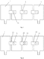
- the junction box described in the embodiment comprises a box body, wherein the box body is provided with a plurality of conducting pieces 1 for connecting solar cell pieces; two adjacent conducting pieces 1 are connected by a diode 2; the conducting pieces 1 at both ends are connected to the outside via a busbar respectively; as illustrated in Fig. 1 , in the prior art, the box body is provided with four conducting pieces 1 connected by three diodes 2, and the forward dissipation power of a first chip 31 on all the diode 2 is the same. It does not seem desirable as the cost is increased greatly once the forward dissipation power of the diode is reduced.
- the method employed in the embodiment is that the forward dissipation power of the diode in the middle is reduced so as to be less than that of the chip of the diodes at both sides.
- the box body of the embodiment is provided with four conducting pieces 1 for connecting solar cell pieces; two adjacent conducting pieces 1 are connected by a diode; the conducting pieces 1 at both ends are connected to the outside via a busbar respectively; wherein the model of a second chip 32 of the middle diode 21 is different from that of the first chip 31 of two-end diodes 22.
- the forward dissipation power of the second chip 32 on the middle diode 21 is less than that of the first chip 31 on the two-end diode 22. Thus, the cost increase is controlled due to the decrease in heating.
- the box body of the embodiment is provided with four conducting pieces 1 for connecting solar cell pieces; two adjacent conducting pieces 1 are connected by a total of three diodes; the conducting pieces 1 at both ends are connected to the outside parts via a busbar respectively; wherein the middle diode 21 is connected parallelly with two first chips 31 respectively so that the forward dissipation power of the two first chips 31 on the middle diode 21 is less than that of the two-end diode 22.
- the cost increase is controlled due to the decrease in heating.
- the box body of the embodiment is provided with four conducting pieces 1 for connecting solar cell pieces; two adjacent conducting pieces 1 are connected by a total of three diodes; the conducting pieces 1 at both ends are connected to the outside parts via a busbar respectively; wherein the surface of a third chip 33 on the middle diode 21 is provided with a trench or groove 34, the forward dissipation power of the third chip 33 is reduced by the trench/groove 34 so as to be less than that of the first chip 31 on the two-end diode 22.
- the cost increase is controlled due to the decrease in heating.
Landscapes
- Engineering & Computer Science (AREA)
- Architecture (AREA)
- Civil Engineering (AREA)
- Structural Engineering (AREA)
- Photovoltaic Devices (AREA)
- Life Sciences & Earth Sciences (AREA)
- Sustainable Development (AREA)
- Sustainable Energy (AREA)
Applications Claiming Priority (1)
| Application Number | Priority Date | Filing Date | Title |
|---|---|---|---|
| CN201610385642.7A CN105790704A (zh) | 2016-06-03 | 2016-06-03 | 太阳能电池用接线盒 |
Publications (1)
| Publication Number | Publication Date |
|---|---|
| EP3252945A1 true EP3252945A1 (de) | 2017-12-06 |
Family
ID=56375503
Family Applications (1)
| Application Number | Title | Priority Date | Filing Date |
|---|---|---|---|
| EP16200338.8A Withdrawn EP3252945A1 (de) | 2016-06-03 | 2016-11-23 | Anschlussdose für solarzelle |
Country Status (6)
| Country | Link |
|---|---|
| US (1) | US9887666B2 (de) |
| EP (1) | EP3252945A1 (de) |
| JP (1) | JP2017221096A (de) |
| KR (1) | KR20170137595A (de) |
| CN (1) | CN105790704A (de) |
| CA (1) | CA2953436A1 (de) |
Families Citing this family (2)
| Publication number | Priority date | Publication date | Assignee | Title |
|---|---|---|---|---|
| JP6661686B2 (ja) * | 2018-03-16 | 2020-03-11 | 矢崎総業株式会社 | 電気接続箱 |
| US11757269B2 (en) | 2021-01-28 | 2023-09-12 | Tyler Uebelhoer | Electrical junction box for installation on metal roofs to accommodate internal wiring of solar panels |
Citations (4)
| Publication number | Priority date | Publication date | Assignee | Title |
|---|---|---|---|---|
| EP1753033A1 (de) * | 2004-05-19 | 2007-02-14 | Angel Co., Ltd.; | Diode mit anschlussleitungs-abschluss für eine solarzelle |
| EP2077579A1 (de) * | 2007-08-13 | 2009-07-08 | Onamba Co., Ltd. | Auf chip montierte doppeldiode |
| JP4699060B2 (ja) | 2005-03-24 | 2011-06-08 | 三菱電機株式会社 | 太陽電池モジュール用端子ボックス装置 |
| EP2728627A1 (de) * | 2012-11-05 | 2014-05-07 | SEMIKRON Elektronik GmbH & Co. KG | Verbindungseinrichtung und Anordnung hiermit und mit einem Photovoltaikmodul |
Family Cites Families (23)
| Publication number | Priority date | Publication date | Assignee | Title |
|---|---|---|---|---|
| JP2005150277A (ja) * | 2003-11-13 | 2005-06-09 | Yukita Electric Wire Co Ltd | 太陽電池モジュール用端子ボックス |
| FR2863775B1 (fr) * | 2003-12-15 | 2006-04-21 | Photowatt Internat Sa | Module photovoltaique avec un dispositif electronique dans l'empilage lamine. |
| JP5144201B2 (ja) * | 2004-05-25 | 2013-02-13 | 木谷電器株式会社 | 太陽電池モジュール用端子ボックス |
| GB2415841B (en) * | 2004-11-08 | 2006-05-10 | Enecsys Ltd | Power conditioning unit |
| ES2348609T3 (es) * | 2005-11-28 | 2010-12-09 | Onamba Co., Ltd. | Caja de terminales para panel de batería solar. |
| US8384243B2 (en) * | 2007-12-04 | 2013-02-26 | Solaredge Technologies Ltd. | Distributed power harvesting systems using DC power sources |
| US9130401B2 (en) * | 2006-12-06 | 2015-09-08 | Solaredge Technologies Ltd. | Distributed power harvesting systems using DC power sources |
| US8963369B2 (en) * | 2007-12-04 | 2015-02-24 | Solaredge Technologies Ltd. | Distributed power harvesting systems using DC power sources |
| US20080149170A1 (en) * | 2006-12-15 | 2008-06-26 | Evergreen Solar, Inc. | Plug-Together Photovoltaic Modules |
| EP2232690B1 (de) * | 2007-12-05 | 2016-08-31 | Solaredge Technologies Ltd. | Parallel geschaltete umrichter |
| EP3561881A1 (de) * | 2007-12-05 | 2019-10-30 | Solaredge Technologies Ltd. | Prüfung eines fotovoltaikplanels |
| IT1390778B1 (it) * | 2008-07-01 | 2011-09-23 | St Microelectronics Srl | Architettura per diodo di by-pass di celle in serie di un pannello fotovoltaico |
| DE102008052037B3 (de) * | 2008-10-16 | 2010-04-08 | Moeller Gmbh | Solarmodul |
| JP2011018674A (ja) * | 2009-07-07 | 2011-01-27 | Kitani Denki Kk | 太陽電池モジュール用端子ボックス |
| EP2457258B1 (de) * | 2009-08-26 | 2015-11-04 | Fraunhofer-Gesellschaft zur Förderung der angewandten Forschung e.V. | Bypass- und schutzschaltung für ein solarmodul und verfahren zum steuern eines solarmoduls |
| US8809671B2 (en) * | 2009-12-08 | 2014-08-19 | Sunpower Corporation | Optoelectronic device with bypass diode |
| US8952672B2 (en) * | 2011-01-17 | 2015-02-10 | Kent Kernahan | Idealized solar panel |
| DE102011002215A1 (de) * | 2011-04-21 | 2012-10-25 | Fpe Fischer Gmbh | Anschlussdose für Solarmodule |
| CN202678374U (zh) * | 2012-08-01 | 2013-01-16 | 山东迪一电子科技有限公司 | 太阳能光伏接线盒用旁路保护模块 |
| CN104467656A (zh) * | 2014-10-24 | 2015-03-25 | 苏州快可光伏电子股份有限公司 | 一种具有高效散热性能的光伏组件接线盒 |
| CN104901622A (zh) * | 2015-05-28 | 2015-09-09 | 常熟市冠日新材料有限公司 | 用于太阳能光伏组件的接线盒 |
| CN205051644U (zh) * | 2015-08-26 | 2016-02-24 | 泰科电子(上海)有限公司 | 光伏接线盒 |
| CN205666792U (zh) * | 2016-06-03 | 2016-10-26 | 浙江人和光伏科技有限公司 | 太阳能电池用接线盒 |
-
2016
- 2016-06-03 CN CN201610385642.7A patent/CN105790704A/zh active Pending
- 2016-11-14 US US15/351,176 patent/US9887666B2/en not_active Expired - Fee Related
- 2016-11-23 EP EP16200338.8A patent/EP3252945A1/de not_active Withdrawn
- 2016-12-01 KR KR1020160162667A patent/KR20170137595A/ko not_active Ceased
-
2017
- 2017-01-04 CA CA2953436A patent/CA2953436A1/en not_active Abandoned
- 2017-02-09 JP JP2017021902A patent/JP2017221096A/ja active Pending
Patent Citations (4)
| Publication number | Priority date | Publication date | Assignee | Title |
|---|---|---|---|---|
| EP1753033A1 (de) * | 2004-05-19 | 2007-02-14 | Angel Co., Ltd.; | Diode mit anschlussleitungs-abschluss für eine solarzelle |
| JP4699060B2 (ja) | 2005-03-24 | 2011-06-08 | 三菱電機株式会社 | 太陽電池モジュール用端子ボックス装置 |
| EP2077579A1 (de) * | 2007-08-13 | 2009-07-08 | Onamba Co., Ltd. | Auf chip montierte doppeldiode |
| EP2728627A1 (de) * | 2012-11-05 | 2014-05-07 | SEMIKRON Elektronik GmbH & Co. KG | Verbindungseinrichtung und Anordnung hiermit und mit einem Photovoltaikmodul |
Also Published As
| Publication number | Publication date |
|---|---|
| US20170353152A1 (en) | 2017-12-07 |
| CA2953436A1 (en) | 2017-12-03 |
| KR20170137595A (ko) | 2017-12-13 |
| US9887666B2 (en) | 2018-02-06 |
| CN105790704A (zh) | 2016-07-20 |
| JP2017221096A (ja) | 2017-12-14 |
Similar Documents
| Publication | Publication Date | Title |
|---|---|---|
| MY197283A (en) | Solar cell photovoltaic module and solar cell photovoltaic assembly | |
| EP3252945A1 (de) | Anschlussdose für solarzelle | |
| CN203719602U (zh) | 一种光伏焊带弯曲度测量装置 | |
| EP3252946A1 (de) | Anschlussdose für solarzelle | |
| CN102593217A (zh) | 一种防热斑智能光伏组件 | |
| CN103412609A (zh) | 光伏并网逆变器的输出功率控制方法 | |
| CN103884444A (zh) | 基于热敏电阻测温和rfid传输的远程监控型光伏接线盒 | |
| Balato et al. | A new strategy for the identification of the optimal operating points in PV applications with distributed MPPT | |
| CN205666792U (zh) | 太阳能电池用接线盒 | |
| CN203827280U (zh) | 基于霍尔传感器和wifi传输的远程监控型光伏接线盒 | |
| CN103856165A (zh) | 一种设有集成汇流带的晶体硅太阳能电池组件 | |
| CN102931241A (zh) | 一种晶体硅组件 | |
| CN108281500A (zh) | 一种新型半片光伏电池组件 | |
| CN103888061A (zh) | 基于半导体测温和fm传输的远程监控型光伏接线盒 | |
| CN207490855U (zh) | 一种太阳能电池组件 | |
| CN203827274U (zh) | 基于半导体测温和wifi传输的远程监控型光伏接线盒 | |
| CN203827277U (zh) | 基于半导体测温和rfid传输的远程监控型光伏接线盒 | |
| CN203827278U (zh) | 基于测电流和电力导线载波的远程监控型光伏接线盒 | |
| CN103888062A (zh) | 基于测电流和电力导线载波的远程监控型光伏接线盒 | |
| CN203824668U (zh) | 基于热敏电阻测温和rfid传输的远程监控型光伏接线盒 | |
| WO2020134900A1 (zh) | 一种太阳电池组件的电气连接方法及采用该方法的太阳电池组件 | |
| CN205040138U (zh) | 自动调压器散热片 | |
| Bastidas-Rodríguez et al. | Model of series-parallel photovoltaic arrays designed for parallel computing | |
| Tiwari et al. | Performance Analysis of 3kW Residential Grid-Connected Photovoltaic System with Microinverter Topology using System Advisor Model | |
| CN204859104U (zh) | 具有dc-dc转换器芯片的光伏组件接线盒 |
Legal Events
| Date | Code | Title | Description |
|---|---|---|---|
| PUAI | Public reference made under article 153(3) epc to a published international application that has entered the european phase |
Free format text: ORIGINAL CODE: 0009012 |
|
| AK | Designated contracting states |
Kind code of ref document: A1 Designated state(s): AL AT BE BG CH CY CZ DE DK EE ES FI FR GB GR HR HU IE IS IT LI LT LU LV MC MK MT NL NO PL PT RO RS SE SI SK SM TR |
|
| AX | Request for extension of the european patent |
Extension state: BA ME |
|
| STAA | Information on the status of an ep patent application or granted ep patent |
Free format text: STATUS: THE APPLICATION IS DEEMED TO BE WITHDRAWN |
|
| 18D | Application deemed to be withdrawn |
Effective date: 20180607 |