EP3253665B1 - Tropfstopper und verpackung dafür - Google Patents
Tropfstopper und verpackung dafür Download PDFInfo
- Publication number
- EP3253665B1 EP3253665B1 EP16700599.0A EP16700599A EP3253665B1 EP 3253665 B1 EP3253665 B1 EP 3253665B1 EP 16700599 A EP16700599 A EP 16700599A EP 3253665 B1 EP3253665 B1 EP 3253665B1
- Authority
- EP
- European Patent Office
- Prior art keywords
- drip
- drip catcher
- stopper
- wall
- bottle
- Prior art date
- Legal status (The legal status is an assumption and is not a legal conclusion. Google has not performed a legal analysis and makes no representation as to the accuracy of the status listed.)
- Active
Links
Images
Classifications
-
- B—PERFORMING OPERATIONS; TRANSPORTING
- B65—CONVEYING; PACKING; STORING; HANDLING THIN OR FILAMENTARY MATERIAL
- B65D—CONTAINERS FOR STORAGE OR TRANSPORT OF ARTICLES OR MATERIALS, e.g. BAGS, BARRELS, BOTTLES, BOXES, CANS, CARTONS, CRATES, DRUMS, JARS, TANKS, HOPPERS, FORWARDING CONTAINERS; ACCESSORIES, CLOSURES, OR FITTINGS THEREFOR; PACKAGING ELEMENTS; PACKAGES
- B65D23/00—Details of bottles or jars not otherwise provided for
- B65D23/06—Integral drip catchers or drip-preventing means
- B65D23/065—Loose or loosely-attached drip catchers or drip preventing means
-
- B—PERFORMING OPERATIONS; TRANSPORTING
- B65—CONVEYING; PACKING; STORING; HANDLING THIN OR FILAMENTARY MATERIAL
- B65D—CONTAINERS FOR STORAGE OR TRANSPORT OF ARTICLES OR MATERIALS, e.g. BAGS, BARRELS, BOTTLES, BOXES, CANS, CARTONS, CRATES, DRUMS, JARS, TANKS, HOPPERS, FORWARDING CONTAINERS; ACCESSORIES, CLOSURES, OR FITTINGS THEREFOR; PACKAGING ELEMENTS; PACKAGES
- B65D5/00—Rigid or semi-rigid containers of polygonal cross-section, e.g. boxes, cartons or trays, formed by folding or erecting one or more blanks made of paper
- B65D5/42—Details of containers or of foldable or erectable container blanks
- B65D5/44—Integral, inserted or attached portions forming internal or external fittings
- B65D5/50—Internal supporting or protecting elements for contents
- B65D5/5028—Elements formed separately from the container body
- B65D5/503—Tray-like elements formed in one piece
Definitions
- the invention relates to a drip stopper for preventing the unwanted drop of drops when pouring from a bottle, especially a wine bottle, in a drinking vessel or the like.
- a drip stopper for preventing the unwanted drop of drops when pouring from a bottle, especially a wine bottle, in a drinking vessel or the like.
- the problem of unwanted drops when pouring bottles into glasses is known in the gastronomy and in the private sector. Because of a single drop of red wine, an otherwise clean tablecloth often needs to be changed. In order to solve this problem, various inserts or attachments have been described in the prior art in or on a bottleneck.
- the invention has for its object to provide a drip stopper that overcomes the above disadvantages and also offers advantages. This object is achieved by the above-mentioned drip stopper with the characterizing features of claim 1.
- the drip stopper according to the invention offers the technical possibilities of using it in the packaging described below and also in an insertion device such as the aforementioned patent application.
- the one-piece drip stopper is made of resilient plastic, which is allowed to handle foodstuffs, e.g. PE.
- a resilient folding device makes it possible that the drip stopper can be varied steplessly in its diameter.
- the drip stopper is universally suitable for bottle necks of various internal diameters, e.g. from 17 mm to 19.5 mm. It is short and can be put together with others to save space. He is also stackable and can be made suitable for the mentioned insertion device. It is easy to make and apply even as a disposable item.
- a packaging for this drip stopper is the subject of claim 7.
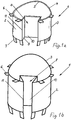
- the in Fig. 1 Tropfstopper shown consists of a substantially cylindrical pipe section 1, which is partially plugged into the neck of an open bottle for the purpose of drop-free pouring.
- the lower part of the pipe section, which extends in the inserted state into the bottle neck, is referred to as insert part 3, the upper part, which protrudes from the bottle neck in the inserted state, as pouring part 4.
- the upper opening of the Ausgiessteils 4 is shaped so that a defined Ausgiesskante 5 is formed. This is achieved in the present example, characterized in that the pipe section is cut above obliquely to its axis.
- a plurality of radially outwardly directed position elements 6 are arranged, which rest in the inserted state of the dropper stopper on the upper edge of the bottle neck and thus limit the insertion depth.
- a plurality of guide elements 7 are formed at the lower end portion of the male part 3. These are directed downwards obliquely to the axis of the male part 3 and facilitate the unerring insertion of the anti-drip into narrower necks.
- the substantially cylindrical wall of the pipe section has on the side opposite the pouring edge 5 a niche-shaped recess 8 which extends in the axial direction over the entire length of the pipe section and is formed by two side walls 9 and a rear wall 10.
- a niche-shaped recess 8 which extends in the axial direction over the entire length of the pipe section and is formed by two side walls 9 and a rear wall 10.
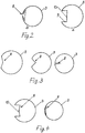
- Fig. 2a schematically shows a cross section of the male part 3, ie a section perpendicular to the axis of the pipe section, with the preferred folding zone 8, in the ready-basic position, such as the drip stopper is delivered.
- the outer diameter of the male part 3 is minimally larger than the inner diameter of the largest intended neck.
- the rear wall 10 is tensioned and bent slightly toward the axis of the male part 3.
- the tilting side walls 9 are forced to lie between the rear wall 10 and the outer wall.
- the rear wall 10 is pulled radially outwardly, as in Fig. 2b it can be seen, which shows the state of the folding zone 8 with plugged drop stopper in a bottleneck with the smallest, mentioned diameter.
- the force required for inserting the drip stopper in the bottle neck generates a tension in the male part 3, as well as in the side walls 9 and the rear wall 10 of the folding zone 8.
- the functioning of the seal is thus based on pressure and back pressure between the male part. 3 and the folding zone 8 is formed by the constriction when the drip stopper is pushed into the neck of the bottle.
- the angle settings between the rear wall 10, side walls 9 and male part 3 specify how and where the side walls 9 have to move when the male part 3 is narrowed.
- the leading edges 11 and the inner edges between the rear wall 10 and the side walls 9 can transmit tension forces between the adjacent areas. In other words, they must not be bent so sharply that they can be kinked without tension. This is preferably achieved in that the edges have a radius of curvature of a few millimeters.
- the folding zone 8 is stretched, while this tension, at the same time, the male part 3 everywhere and uniformly pressed against the bottle neck. This creates a seal. This has the effect that no wine can penetrate between plug-in part 3 and bottleneck.
- FIG. 3 Another possibility for the design of an open angle folding zone is shown, left in the ready state, ie as it is delivered, in the middle with an approximately rectangular position of the folding zone in a bottleneck with medium and right in a bottleneck with the smallest inner diameter.
- Fig. 4 shows a similar variant as Fig. 2 , but with an outwardly directed kink in the rear wall 10.
- the rear wall 10 when tightening the male part 3, pressed closer to the bottle wall than in the version according to Fig. 2 ,
- the drip stoppers can be stacked to save space by nesting. To make this possible, the following is provided:
- the pouring part 4 has a thinner wall than the plug-in part 3.
- the inside diameter of the pouring part 4 corresponds approximately to the outside diameter of the plug-in part 3.
- a support is formed on the inside.
- the lower portion of the male member is tapered on a short section to facilitate insertion into the neck of the bottle. In the same length as this taper, the folding zone 8 is omitted.
- the guide elements 7 are arranged so that they are in the stack laterally of the folding zone 8 and the support. Thus, if the drip stoppers are inserted into one another, the plug-in part 3 of the upper drip-stopper sits on the folding zone 8 and the support of the lower drip stopper. Stacked a drip stopper needs only as much space as the plug 3 is long.
- the drip stopper is made of resilient, tough, hydrophobic plastic, e.g. PE.
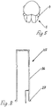
- Fig. 5 shows a drip stopper, in which, in contrast to the drip stopper with guide elements of the lower portion of the male part is tapered. This rejuvenation facilitates the unerring insertion of the drip stopper into the bottleneck with the smallest diameter mentioned above.
- the back wall or crest of the fold zone is cut to the end of the taper. This ensures that the taper can not influence the uniform contact pressure of the male part to the neck of the bottle.
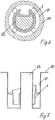
- 6 and 7 show schematically a packaging in which individual or stacked drip stoppers are stored without being able to touch them with your fingers.
- the packaging consists of a decorative, flat cardboard box with a hinged lid, similar to a box of chocolates. Inside, there is a downwardly deep-drawn, flat on the surface sheet 20.
- This sheet 20 has a plurality of annular recesses, as a stacking space 21, in which drip stopper 1 individually or preferably stacked, can be stored with the pouring parts 4 upwards;
- the outer diameter of this stacking space 21 corresponds approximately to the outer diameter of the circle of the end portions of the position elements 6.
- a likewise deep-drawn column 22 is formed, which is adapted to the inner contours of the drip stopper 1, with some distance.
- the column serves as a straightening element.
- the drip stoppers 1 thus sit and stacked in the stacking space 21, and indeed so deep that they can not be touched with the fingers, ie between the surface of the package and the Ausgiesskante 5 of the uppermost drip stopper 1, a distance is formed.
- the stacking room where the drip stoppers sit is narrower than a finger is thick.
- the inner diameter of the pouring part 4, of the respective lower drop stopper 1 corresponds, as mentioned, approximately to the outer diameter of the plug-in part, the next upper drop stopper 1, so that the upper drip stopper is easily held by the lower one.
- the depressions in the film 20 are made narrower in the lower area than in the upper area.
- the lower area of the depression is adapted to the drip stopper so that the position elements 5 of the lowest drip stopper are slightly clamped. Since this is thereby pressed against the packaging and the upper drip stops are held by the respective lower, there is no danger that the Stack can slip out of the package, even if it is turned upside down.
- Inserting device 25 shown consists of a handle 26 and a pressing member 27.
- the handle 26 consists of a downwardly open tube, which leads to the lower end portion of the pressing member 27.
- the inner diameter of the tube is minimally smaller than the outer diameter of the circle of the pouring part 2 of the drip stopper 1, when it is not stretched.
- the outer diameter of the pressing member 27 is about the same size as the outer diameter of the recess in the film 20 and slightly smaller than the outer circle of the position elements 6 of the drip stopper 1.
- the straight cut lower end portion of the tube is, like the lower surface of the pressing member 27, perpendicular to the axis of the pipe.
- the pressing member 27 is closed at the bottom, to the edge of the tube.
- the insertion tool is grasped on the handle and the pressing part is guided into the circular depression of the packaging, ie into the stacking space 21.
- the depression shows a drip stopper 1 with its pouring part 4 upwards.
- the tube which has a short extension in the lower section, is slipped over this pouring part 4.
- the tube clamps the pouring part 4 of the dropper stopper and holds it by compressing it.
- the plug-in part 3 of the drip-stopper 1 also becomes smaller in its circumference, so that it can become detached from the lower drip-stopper.
- the tube (handle) is raised with the clamped pouring part 4. Now the drip stopper, with the insertion device 25, pressed into the neck of the bottle until the Positioning elements 6 sit on the edge of the bottle neck. The drip stopper 1 is now firmly in the neck of the bottle.
- the diameter of the dropper stopper 1 and with it the diameter of the pouring part 4 becomes smaller.
- the pouring part 4 is released from the insertion device 25.
- the insertion device 25 can be lifted and placed in the packaging, or a new drop stopper 1 can be detected and placed in a bottle neck.
- the tube is supplemented by a flat profile in the receiving space for pouring part 4, which is located when receiving the drip stopper in the interior of the male part 3 and presses against the rear wall 10 lightly.
- This flat profile may extend to the lower end portion of the male part 3.
Landscapes
- Engineering & Computer Science (AREA)
- Mechanical Engineering (AREA)
- Packages (AREA)
Description
- Die Erfindung betrifft einen Tropfstopper zum Verhindern des unerwünschten Abfallens von Tropfen beim Eingiessen aus einer Flasche, vor allem einer Weinflasche, in ein Trinkgefäss oder dergl.
Das Problem unerwünschter Tropfen beim Eingiessen aus Flaschen in Gläser ist aus der Gastronomie und aus dem privaten Bereich bekannt. Wegen eines einzigen Tropfens Rotwein muss oft ein ansonsten sauberes Tischtuch gewechselt werden. Um dieses Problem zu lösen wurden im Stand der Technik verschiedene Einsätze oder Aufsätze in bzw. auf einen Flaschenhals beschrieben. - In der internationalen Patentanmeldung Nr.
WO2012/175571 (PCT/EP 2012/061880 NL1020238 - Der Erfindung liegt die Aufgabe zugrunde, einen Tropfstopper bereitzustellen, der obige Nachteile behebt und zusätzlich Vorteile bietet.
Diese Aufgabe wird gelöst durch den eingangs erwähnten Tropfstopper mit den kennzeichnenden Merkmalen des Anspruchs 1. - Der erfindungsgemässe Tropfstopper bietet die technischen Möglichkeiten, diesen in der nachfolgend beschriebenen Verpackung und auch in einem Einsetzgerät, wie der genannten Patentanmeldung beschrieben, einzusetzen. Der aus einem Stück hergestellte Tropfstopper besteht aus rückstellfähigem Kunststoff, der im Umgang mit Lebensmitteln erlaubt ist, wie z.B. PE. Eine federnde Falteinrichtung macht es möglich, dass der Tropfstopper in seinem Durchmesser stufenlos verändert werden kann. Somit ist der Tropfstopper universell passend für Flaschenhälse von verschiedenen Innendurchmessern, z.B. von 17 mm bis 19.5 mm. Er ist kurz und kann mit anderen platzsparend ineinander gesteckt werden. Er ist ausserdem stapelbar und kann für das erwähnte Einsetzgerät passend gemacht werden. Er ist einfach, auch als Wegwerfartikel, herzustellen und anzuwenden.
- Eine Verpackung für diesen Tropfstopper ist Gegenstand des Anspruchs 7.
- Im Folgenden werden anhand der beiliegenden Zeichnungen bevorzugte Ausführungsbeispiele beschrieben. Es zeigen:
- Fig. 1
- schematische perspektivische Darstellungen eines erfindungsgemässen Tropfstoppers und zwar a) im einsatzbereiten Zustand und b) im eingesetzten Zustand;
- Fig. 2
- schematische Querschnitte desselben Tropfstoppers in den beiden genannten Zuständen;
- Fig. 3, 4
- schematische Querschnitte alternativer Versionen von erfindungsgemässen Tropfstoppern in verschiedenen Zuständen;
- Fig. 5
- eine schematische Darstellung einer anderen Version eines Tropfstoppers;
- Fig. 6
- eine schematische Schnittdarstellung von Tropfstoppern in einer Verpackung;
- Fig. 7
- ein schematischer axialer Schnitt einer Verpackung;
- Fig. 8
- eine schematische Schnittzeichnung eines Einsetzgerätes für Tropfstopper.
- Der in
Fig. 1 dargestellte Tropfstopper besteht aus einem im Wesentlichen zylindrischen Rohrstück 1, das zum Zweck des tropfenfreien Ausgiessens teilweise in den Hals einer geöffneten Flasche gesteckt wird. Der in der Zeichnung untere Teil des Rohrstücks, der sich im eingesetzten Zustand in den Flaschenhals erstreckt, wird als Einsteckteil 3, der obere Teil, der im eingesetzten Zustand aus dem Flaschenhals herausragt, als Ausgiessteil 4 bezeichnet. - Die obere Öffnung des Ausgiessteils 4 ist so geformt dass eine definierte Ausgiesskante 5 gebildet ist. Dies ist beim vorliegenden Beispiel dadurch erreicht, dass das Rohrstück oben schräg zu seiner Achse geschnitten ist. Zwischen dem Ausgiessteil 4 und dem Einsteckteil 3 sind mehrere radial nach aussen gerichtete Positionselemente 6 angeordnet, die im eingesetzten Zustand des Tropfstoppers auf der Oberkante des Flaschenhalses aufliegen und damit die Einstecktiefe begrenzen. Am unteren Endabschnitt des Einsteckteils 3, sind mehrere Leitelemente 7 angeformt. Diese sind nach unten hin schräg zur Achse des Einsteckteils 3 hin gerichtet und erleichtern das treffsichere Einführen des Tropfstoppers in engere Flaschenhälse.
- Die im Wesentlichen zylindrische Wand des Rohrstücks weist auf der der Ausgiesskante 5 gegenüber liegenden Seite einen nischenförmigen Rücksprung 8 auf, der sich in axialer Richtung über die gesamte Länge des Rohrstücks erstreckt und durch zwei Seitenwände 9 und eine Rückwand 10 gebildet wird. Wie nachfolgend anhand der
Fig. 2 erläutert, werden die von den Seitenwänden mit der Mantelfläche gebildeten Vorderkanten 11 des Rücksprungs beim Zusammendrücken des zylindrischen Bereichs des Rohrstücks einander angenähert. Dadurch faltet sich der Rücksprung zusammen und wird daher in der folgenden Beschreibung auch als Faltzone 8 bezeichnet. -
Fig. 2a zeigt schematisch dargestellt einen Querschnitt des Einsteckteils 3, d.h. einen Schnitt senkrecht zur Achse des Rohrstücks, mit der bevorzugten Faltzone 8, in der einsatzbereiten Grundstellung, wie der Tropfstopper angeliefert wird. In dieser Grundstellung, ist der Aussendurchmesser des Einsteckteils 3 minimal grösser als der Innendurchmesser des grössten vorgesehenen Flaschenhalses. Beim Einstecken des Tropfstoppers in den Flaschenhals wird der Einsteckteil 3 verengt. Gleichzeitig werden die Vorderkanten 11 näher aneinander geschoben. - Die Rückwand 10 wird gespannt und leicht zur Achse des Einsteckteils 3 hin gebogen. Die kippenden Seitenwände 9 werden gezwungen, sich zwischen die Rückwand 10 und die Aussenwand zu legen. Zwangsläufig wird auch die Rückwand 10 radial nach aussen gezogen, wie in
Fig. 2b ersichtlich, welche den Zustand der Faltzone 8 bei eingestecktem Tropfstopper in einen Flaschenhals mit dem kleinsten, erwähnten Durchmesser zeigt. - Die Kraft, die zum Einsetzen des Tropfstoppers in den Flaschenhals benötigt wird, erzeugt eine Spannung im Einsteckteil 3, sowie in den Seitenwänden 9 und der Rückwand 10 der Faltzone 8. Das Funktionieren der Abdichtung beruht also auf Druck und Gegendruck, der zwischen dem Einsteckteil 3 und der Faltzone 8 durch die Verengung entsteht, wenn der Tropfstopper in den Flaschenhals geschoben wird. Die Winkeleinstellungen zwischen Rückwand 10, Seitenwänden 9 und Einsteckteil 3 geben vor, wie und wohin sich die Seitenwände 9 zu bewegen haben, wenn der Einsteckteil 3 verengt wird.
- Um diese Funktion, vor allem das Andrücken an die Innenseite des Flaschenhalses, sicherzustellen, ist es notwendig, dass die Vorderkanten 11 und die Innenkanten zwischen Rückwand 10 und den Seitenwänden 9 Spannungskräfte zwischen den angrenzenden Bereichen übertragen können. Mit anderen Worten dürfen sie nicht so scharf abgekantet sein, dass sie spannungslos geknickt werden können. Vorzugsweise wird dies dadurch erreicht, dass die Kanten einen Krümmungsradius von wenigen Millimetern aufweisen.
- Durch das Verengen des Einsteckteils 3 wird die Faltzone 8 gespannt, während diese Spannung, gleichzeitig, den Einsteckteil 3 überall und gleichmässig an den Flaschenhals presst. Dadurch entsteht eine Dichtung. Dies bewirkt, dass zwischen Einsteckteil 3 und Flaschenhals kein Wein durchdringen kann.
- Auch kann kein Wein im Bereich der Faltzone 8 durchfliessen, weil hier die rückwärts strömende Luft dies verhindert. Zudem fliesst der Wein, beim korrekten Einschenken, nur im unteren Bereich des Durchgangs.
- In
Fig. 3 ist eine weitere Möglichkeit für die Gestaltung einer Faltzone mit offenem Winkel dargestellt, und zwar links im einsatzbereiten Zustand, d.h. so wie es angeliefert wird, in der Mitte mit einer etwa rechtwinkligen Stellung der Faltzone in einem Flaschenhals mit mittlerem und rechts in einem Flaschenhals mit kleinstem Innendurchmesser. -
Fig. 4 zeigt eine ähnliche Variante wieFig. 2 , jedoch mit einem nach aussen gerichteten Knick in der Rückwand 10. Bei dieser Variante wird der Rückwand 10, beim Verengen des Einsteckteils 3, näher an die Flaschenwand gedrückt als bei der Version gemässFig. 2 . - Die Tropfstopper können durch Ineinanderstecken platzsparend gestapelt werden. Um dies zu ermöglichen, ist folgendes vorgesehen:
Der Ausgiessteil 4 ist dünnwandiger als der Einsteckteil 3. Der Innendurchmesser des Ausgiessteils 4 entspricht in etwa dem Aussendurchmesser des Einsteckteils 3. Dadurch entsteht zwischen Ausgiessteil und Einsteckteil an der Wandinnenseite ein umlaufender Absatz in dem Bereich in welchem aussen die Positionselemente 6 angeformt sind. Im Bereich des Ausgiessteils 4, auf gleicher Höhe mit der Oberkante der Faltzone 8 ist innen eine Stütze angeformt. Der untere Bereich des Einsteckteils ist auf einem kurzen Abschnitt verjüngt, um das Einschieben in den Flaschenhals zu erleichtern. In gleicher Länge, wie diese Verjüngung ist die Faltzone 8 weggelassen. Die Leitelemente 7 sind so angeordnet, dass sie sich im Stapel seitlich der Faltzone 8 und der Stütze befinden. Wenn also die Tropfstopper ineinander gesteckt sind, sitzt der Einsteckteil 3 des oberen Tropfstoppers auf der Faltzone 8 und der Stütze des unteren Tropfstoppers. Gestapelt braucht ein Tropfstopper nur so viel Platz, wie der Einsteckteil 3 lang ist. - Der Tropfstopper besteht aus rückstellfähigem, zähem, hydrophobem Kunststoff, z.B. PE.
- Für die Gestaltung der Faltzone gibt es weitere Möglichkeiten. So kann z.B. anstelle der Seitenwände und der Rückwand eine Wölbung nach innen ausgebildet sein. Das Prinzip bleibt dasselbe.
-
Fig. 5 zeigt einen Tropfstopper, bei dem im Unterschied zum Tropfstopper mit Leitelementen der untere Bereich des Einsteckteils verjüngt ist. Durch diese Verjüngung wird das treffsichere Einführen des Tropfstoppers in den Flaschenhals mit dem kleinsten oben erwähnten Durchmesser, erleichtert. Die Rückwand oder der Scheitel der Faltzone ist bis zum Ende der Verjüngung, eingeschnitten. Damit wird erreicht, dass die Verjüngung keinen Einfluss nehmen kann auf den gleichmässigen Anpressdruck des Einsteckteils an den Flaschenhals. -
Fig. 6 und 7 zeigen schematisch dargestellt, eine Verpackung, in der einzelne oder gestapelte Tropfstopper gelagert werden, ohne diese mit den Fingern berühren zu können. - Die Verpackung besteht aus einer dekorativen, flachen Kartonschachtel mit einem Klappdeckel, ähnlich wie eine Pralinenschachtel. Im Inneren befindet sich eine nach unten tiefgezogene, auf der Oberfläche flache Folie 20. Diese Folie 20 weist mehrere ringförmige Vertiefungen, als Stapelraum 21 auf, in denen Tropfstopper 1 einzeln, oder vorzugsweise gestapelt, mit den Ausgiessteilen 4 nach oben gelagert werden können;.
Der äussere Durchmesser dieses Stapelraumes 21 entspricht in etwa dem Aussendurchmesser des Kreises der Endabschnitte der Positionselemente 6. Mittig im Stapelraum 21 ist eine ebenfalls tiefgezogene Säule 22 gebildet, welche an den inneren Konturen des Tropfstoppers 1, mit etwas Abstand, angepasst ist. Die Säule dient als Richtelement.
Die Tropfstopper 1 sitzen also gerichtet und gestapelt im Stapelraum 21 und zwar so tief, dass sie mit den Fingern nicht berührt werden können, d.h. zwischen der Oberfläche der Verpackung und der Ausgiesskante 5 des obersten Tropfstoppers 1 ist ein Abstand gebildet. Der Stapelraum, in dem die Tropfstopper sitzen ist schmäler, als ein Finger dick ist.
Beim Stapel sitzt der jeweils obere Tropfstopper 1, im Ausgiessteil 4 des jeweils darunter befindlichen. Der Innendurchmesser des Ausgiessteils 4, des jeweils unteren Tropfstoppers 1, entspricht, wie erwähnt, in etwa dem Aussendurchmesser des Einsteckteils, des nächst oberen Tropfstoppers 1, sodass der obere Tropfstopper vom unteren leicht festgehalten wird. - Die Vertiefungen in der Folie 20 sind im unteren Bereich enger gestaltet, als im oberen Bereich. Der untere Bereich der Vertiefung ist dem Tropfstopper so angepasst, dass die Positionselemente 5 des untersten Tropfstoppers leicht eingeklemmt sind. Da dieser dadurch an der Verpackung angedrückt wird und die oberen Tropfstopper von den jeweils unteren festgehalten werden, besteht keine Gefahr, dass der Stapel aus der Verpackung rutschen kann, auch wenn diese auf den Kopf gestellt wird.
- Das in
Fig. 8 gezeigte Einsetzgerät 25 besteht aus einem Handgriff 26 und einem Drückteil 27. Der Handgriff 26 besteht aus einem unten offenen Rohr, welches bis zum unteren Endabschnitt des Drückteils 27 führt. Der Innendurchmesser des Rohres ist minimal kleiner als der Aussendurchmesser des Kreises des Ausgiessteils 2 des Tropfstoppers 1, wenn dieser nicht gespannt ist. Der Aussendurchmesser des Drückteils 27 ist etwa gleich gross wie der äussere Durchmesser der Vertiefung in der Folie 20 und etwas kleiner als der äussere Kreis der Positionselemente 6 des Tropfstoppers 1. Der gerade geschnittene untere Endabschnitt des Rohres steht, wie die untere Fläche des Drückteils 27, rechtwinklig zur Achse des Rohres. Der Drückteil 27 ist unten, bis zum Rand des Rohres, geschlossen. - Zum Herausnehmen aus der Verpackung und Einsetzen in den Flaschenhals wird das Einsetzwerkzeug am Griff erfasst und der Drückteil in die kreisrunde Vertiefung der Verpackung, d.h. in den Stapelraum 21, geführt. In der Vertiefung zeigt ein Tropfstopper 1 mit seinem Ausgiessteil 4 nach oben. Das Rohr, welches im unteren Abschnitt eine kurze Erweiterung aufweist, wird über diesen Ausgiesssteil 4 gestülpt. Das Rohr klemmt den Ausgiessteil 4 des Tropfstoppers ein und hält ihn fest, indem er diesen zusammendrückt. Gleichzeitig wird auch der Einsteckteil 3 des Tropfstoppers 1 in seinem Umfang kleiner, sodass er sich vom unteren Tropfstopper lösen kann. Das Rohr (Handgriff) wird mit dem festgeklemmten Ausgiessteil 4 angehoben. Nun wird der Tropfstopper, mit dem Einsetzgerät 25, in den Flaschenhals gedrückt, bis die Positionselemente 6 auf dem Rande des Flaschenhalses sitzen. Der Tropfstopper 1 sitzt nun fest im Flaschenhals.
- Durch das Eindrücken in den Flaschenhals wird der Durchmesser des Tropfstoppers 1 und mit ihm der Durchmesser des Ausgiessteils 4 kleiner. So löst sich der Ausgiessteil 4 vom Einsetzgerät 25. Das Einsetzgerät 25 kann abgehoben und in die Verpackung gelegt werden, oder es kann ein neuer Tropfstopper 1 erfasst und in einen Flaschenhals gesetzt werden.
- In einer anderen Variante wird das Rohr durch ein Flachprofil im Aufnahmeraum für Ausgiessteil 4 ergänzt, das sich beim Aufnehmen des Tropfstoppers im Inneren des Einsteckteils 3 befindet und sich an den Rückwand 10 leicht anpresst. Dieses Flachprofil kann sich bis zum unteren Endabschnitt des Einsteckteils 3 erstrecken. Diese Variante ist vorteilhaft bei sehr kurzem Ausgiessteil. Selbstverständlich wird die tiefgezogene Verpackungsfolie 20 angepasst.
Claims (7)
- Tropfstopper (1) zum Verhindern des unerwünschten Abfallens von Tropfen beim Eingiessen aus einer Flasche, vor allem einer Weinflasche, in ein Trinkgefäss oder dergl., mit einer im Wesentlichen zylindrischen Wand (2), einem Einsteckteil (3) zum Einführen in einen Flaschenhals und einem Ausgiessteil (4), dadurch gekennzeichnet, dass die Wand einen nischenförmigen achsparallelen Rücksprung (8) aufweist, der sich über die axiale Länge der Wand erstreckt.
- Tropfstopper nach Anspruch 1, dadurch gekennzeichnet, dass der Rücksprung (8) einen etwa U-förmigen Querschnitt hat.
- Tropfstopper nach Anspruch 1, dadurch gekennzeichnet, dass der Rücksprung (8) einen etwa V-förmigen Querschnitt hat.
- Tropfstopper nach Anspruch 2, dadurch gekennzeichnet, dass der Rücksprung (8) eine bogenförmige oder geknickte Rückwand (10) hat.
- Tropfstopper nach einem der vorangehenden Ansprüche, gekennzeichnet durch aussen an der Wand (2) angeordnete Positionselemente (6) zur Begrenzung der Einstecktiefe.
- Tropfstopper nach einem der vorangehenden Ansprüche, gekennzeichnet durch unten an der Wand (2) angeordnete Führungselemente (7) zur Erleichterung des Einsteckens in einen engen Flaschenhals.
- Verpackung für Tropfstopper nach einem der vorangehenden Ansprüche, gekennzeichnet durch ringförmige Vertiefungen (21) in einem Trägerelement (20) mit konzentrisch in den Vertiefungen angeordneten Säulen (22), wobei die Tiefe der Vertiefungen grösser ist als die Höhe eines aufzunehmenden Stapels von Tropfstoppern.
Applications Claiming Priority (2)
| Application Number | Priority Date | Filing Date | Title |
|---|---|---|---|
| CH00123/15A CH710688A1 (de) | 2015-02-02 | 2015-02-02 | Antitropfvorrichtung. |
| PCT/EP2016/050625 WO2016124365A1 (de) | 2015-02-02 | 2016-01-14 | Tropfstopper und verpackung dafür |
Publications (2)
| Publication Number | Publication Date |
|---|---|
| EP3253665A1 EP3253665A1 (de) | 2017-12-13 |
| EP3253665B1 true EP3253665B1 (de) | 2018-10-17 |
Family
ID=53199761
Family Applications (1)
| Application Number | Title | Priority Date | Filing Date |
|---|---|---|---|
| EP16700599.0A Active EP3253665B1 (de) | 2015-02-02 | 2016-01-14 | Tropfstopper und verpackung dafür |
Country Status (4)
| Country | Link |
|---|---|
| US (2) | US10329051B2 (de) |
| EP (1) | EP3253665B1 (de) |
| CH (1) | CH710688A1 (de) |
| WO (1) | WO2016124365A1 (de) |
Families Citing this family (1)
| Publication number | Priority date | Publication date | Assignee | Title |
|---|---|---|---|---|
| WO2026027940A1 (de) * | 2024-07-30 | 2026-02-05 | Goetschi Rudolf | System zum vermeiden von tropfen |
Family Cites Families (19)
| Publication number | Priority date | Publication date | Assignee | Title |
|---|---|---|---|---|
| US184315A (en) * | 1876-11-14 | Improvement in combined stopper and dropper for bottles | ||
| US2317046A (en) * | 1941-03-14 | 1943-04-20 | Fleming Paul Nelson | Anchoring means for sanitary drinking caps |
| US2272549A (en) * | 1941-08-04 | 1942-02-10 | Richard E Deschner | Pouring attachment for containers |
| US2649090A (en) * | 1950-09-29 | 1953-08-18 | American Cyanamid Co | Rubber closure for pharmaceutical vials |
| US2763402A (en) * | 1952-06-10 | 1956-09-18 | Livingstone Jay Gould | Adapter |
| US2848145A (en) * | 1955-03-17 | 1958-08-19 | Jay G Livingstone | Pouring adapter |
| US2750063A (en) * | 1955-07-14 | 1956-06-12 | Opsitnik William | Non-drip insert for bottles |
| US2908426A (en) * | 1957-03-28 | 1959-10-13 | Schenley Ind Inc | Flexible spout combination stopper and pouring device |
| US3217935A (en) * | 1964-05-11 | 1965-11-16 | Procter & Gamble | Pouring fitment |
| US4222504A (en) * | 1978-04-21 | 1980-09-16 | Bernard Ackerman | Drip preventive spout particularly adapted for use in pouring wines |
| US4501361A (en) * | 1984-02-01 | 1985-02-26 | Communications Packaging Corporation | Printer thimble element holder |
| US5435467A (en) * | 1994-04-20 | 1995-07-25 | Phoenix Closures, Inc. | Stackable dispenser closure |
| US7097076B1 (en) * | 2000-10-11 | 2006-08-29 | Unilever Home & Personal Care Usa, Division Of Conopco, Inc. | Fitment and bottle |
| NL1020238C1 (nl) * | 2002-03-22 | 2003-09-23 | Louisa Maria Fr Terpstra-Mossa | Druppelbreker voor in een flessenhals of andere cilindrische vorm of houder, die direct en preventief vloeistofdruppels breekt d.m.v. een scherpe snijrand aan de bovenzijde van deze druppelbreker. |
| NL1022297C2 (nl) * | 2003-01-02 | 2004-07-22 | Vacu Vin Innovations Ltd | Uitschenkinrichting. |
| GB0622969D0 (en) * | 2006-11-17 | 2006-12-27 | Obrist Closures Switzerland | Improvements in or relating to bottle fitments |
| US8091746B2 (en) * | 2008-05-29 | 2012-01-10 | David Gotler | Tamper-evident container with pour-out container fitment |
| WO2015103494A1 (en) * | 2014-01-03 | 2015-07-09 | Schlumberger Technology Corporation | Graph partitioning to distribute wells in parallel reservoir simulation |
| CH712432A1 (de) * | 2016-05-03 | 2017-11-15 | Hoffmann Neopac Ag | Tube mit Drosseleinsatz. |
-
2015
- 2015-02-02 CH CH00123/15A patent/CH710688A1/de not_active Application Discontinuation
-
2016
- 2016-01-14 US US15/548,127 patent/US10329051B2/en active Active
- 2016-01-14 EP EP16700599.0A patent/EP3253665B1/de active Active
- 2016-01-14 WO PCT/EP2016/050625 patent/WO2016124365A1/de not_active Ceased
-
2019
- 2019-05-23 US US16/420,223 patent/US10518935B2/en active Active
Non-Patent Citations (1)
| Title |
|---|
| None * |
Also Published As
| Publication number | Publication date |
|---|---|
| US20180009568A1 (en) | 2018-01-11 |
| US10518935B2 (en) | 2019-12-31 |
| US20190276185A1 (en) | 2019-09-12 |
| EP3253665A1 (de) | 2017-12-13 |
| US10329051B2 (en) | 2019-06-25 |
| CH710688A1 (de) | 2016-08-15 |
| WO2016124365A1 (de) | 2016-08-11 |
Similar Documents
| Publication | Publication Date | Title |
|---|---|---|
| DE69206120T2 (de) | Vorrichtung umfassend einen mit einem Schlitzventil als Entlüftungsventil versehenen Behälter und eine in diesem Behälter enthaltene Flüssigkeit. | |
| DE3854305T2 (de) | Verfahren zum Füllen oben offener Behälter mit quadratischem Querschnitt. | |
| DE102009019723B4 (de) | Trichter mit einer elastischen Verbindungsöffnung | |
| DE2334451A1 (de) | Behaelterverschluss und verfahren zum anbringen und loesen dieses verschlusses | |
| CH617145A5 (de) | ||
| DE102004023796A1 (de) | Dose | |
| WO2012097396A1 (de) | Universelle verschlussvorrichtung | |
| EP1254842A1 (de) | Kunststoffbehälter | |
| CH715953A2 (de) | Verschlusskappe zum Verschliessen eines Behälters und Behälter mit einer solchen unverlierbar gehaltenen Verschlusskappe. | |
| EP3253665B1 (de) | Tropfstopper und verpackung dafür | |
| EP3241781B1 (de) | Tube mit drosseleinsatz | |
| EP2256058A2 (de) | Ausgabeeinrichtung für flüssige Medien in einem Behälter sowie Dichtung für solche Behälter | |
| DE2432733C3 (de) | Dosendeckel | |
| WO2012072207A1 (de) | Behältnis, insbesondere für getränke | |
| WO2000026116A1 (de) | Ventil für die abgabe von unter druck stehenden flüssigkeiten | |
| DE202016008566U1 (de) | Flüssigkeitsbehandlungskartusche und Flüssigkeitsbehandlungssystem | |
| DE102009057415B4 (de) | Behälter für Lebensmittel | |
| DE602005005214T2 (de) | Ventile für trinkbecher | |
| DE102011105480B3 (de) | Trichter für eine Babyflasche | |
| EP1755973A1 (de) | Verschlusselement | |
| DE3418530A1 (de) | Vorrichtung zum verstopfen von behaeltern mit einem hals | |
| WO2016045653A2 (de) | Ausgiesser | |
| DE2614538A1 (de) | Verschluss fuer eine flasche | |
| WO2021198086A1 (de) | Pipettenspitze | |
| EP3825284B1 (de) | Filter, insbesondere filter für trinkflaschen |
Legal Events
| Date | Code | Title | Description |
|---|---|---|---|
| STAA | Information on the status of an ep patent application or granted ep patent |
Free format text: STATUS: THE INTERNATIONAL PUBLICATION HAS BEEN MADE |
|
| PUAI | Public reference made under article 153(3) epc to a published international application that has entered the european phase |
Free format text: ORIGINAL CODE: 0009012 |
|
| STAA | Information on the status of an ep patent application or granted ep patent |
Free format text: STATUS: REQUEST FOR EXAMINATION WAS MADE |
|
| 17P | Request for examination filed |
Effective date: 20170904 |
|
| AK | Designated contracting states |
Kind code of ref document: A1 Designated state(s): AL AT BE BG CH CY CZ DE DK EE ES FI FR GB GR HR HU IE IS IT LI LT LU LV MC MK MT NL NO PL PT RO RS SE SI SK SM TR |
|
| AX | Request for extension of the european patent |
Extension state: BA ME |
|
| DAV | Request for validation of the european patent (deleted) | ||
| DAX | Request for extension of the european patent (deleted) | ||
| GRAP | Despatch of communication of intention to grant a patent |
Free format text: ORIGINAL CODE: EPIDOSNIGR1 |
|
| STAA | Information on the status of an ep patent application or granted ep patent |
Free format text: STATUS: GRANT OF PATENT IS INTENDED |
|
| INTG | Intention to grant announced |
Effective date: 20180628 |
|
| GRAS | Grant fee paid |
Free format text: ORIGINAL CODE: EPIDOSNIGR3 |
|
| GRAA | (expected) grant |
Free format text: ORIGINAL CODE: 0009210 |
|
| STAA | Information on the status of an ep patent application or granted ep patent |
Free format text: STATUS: THE PATENT HAS BEEN GRANTED |
|
| AK | Designated contracting states |
Kind code of ref document: B1 Designated state(s): AL AT BE BG CH CY CZ DE DK EE ES FI FR GB GR HR HU IE IS IT LI LT LU LV MC MK MT NL NO PL PT RO RS SE SI SK SM TR |
|
| REG | Reference to a national code |
Ref country code: GB Ref legal event code: FG4D Free format text: NOT ENGLISH |
|
| REG | Reference to a national code |
Ref country code: CH Ref legal event code: EP |
|
| REG | Reference to a national code |
Ref country code: IE Ref legal event code: FG4D Free format text: LANGUAGE OF EP DOCUMENT: GERMAN |
|
| REG | Reference to a national code |
Ref country code: DE Ref legal event code: R096 Ref document number: 502016002271 Country of ref document: DE Ref country code: AT Ref legal event code: REF Ref document number: 1053728 Country of ref document: AT Kind code of ref document: T Effective date: 20181115 |
|
| REG | Reference to a national code |
Ref country code: CH Ref legal event code: NV Representative=s name: BRAUNPAT BRAUN EDER AG, CH |
|
| REG | Reference to a national code |
Ref country code: NL Ref legal event code: MP Effective date: 20181017 |
|
| REG | Reference to a national code |
Ref country code: LT Ref legal event code: MG4D |
|
| PG25 | Lapsed in a contracting state [announced via postgrant information from national office to epo] |
Ref country code: NL Free format text: LAPSE BECAUSE OF FAILURE TO SUBMIT A TRANSLATION OF THE DESCRIPTION OR TO PAY THE FEE WITHIN THE PRESCRIBED TIME-LIMIT Effective date: 20181017 |
|
| PG25 | Lapsed in a contracting state [announced via postgrant information from national office to epo] |
Ref country code: ES Free format text: LAPSE BECAUSE OF FAILURE TO SUBMIT A TRANSLATION OF THE DESCRIPTION OR TO PAY THE FEE WITHIN THE PRESCRIBED TIME-LIMIT Effective date: 20181017 Ref country code: IS Free format text: LAPSE BECAUSE OF FAILURE TO SUBMIT A TRANSLATION OF THE DESCRIPTION OR TO PAY THE FEE WITHIN THE PRESCRIBED TIME-LIMIT Effective date: 20190217 Ref country code: BG Free format text: LAPSE BECAUSE OF FAILURE TO SUBMIT A TRANSLATION OF THE DESCRIPTION OR TO PAY THE FEE WITHIN THE PRESCRIBED TIME-LIMIT Effective date: 20190117 Ref country code: PL Free format text: LAPSE BECAUSE OF FAILURE TO SUBMIT A TRANSLATION OF THE DESCRIPTION OR TO PAY THE FEE WITHIN THE PRESCRIBED TIME-LIMIT Effective date: 20181017 Ref country code: LT Free format text: LAPSE BECAUSE OF FAILURE TO SUBMIT A TRANSLATION OF THE DESCRIPTION OR TO PAY THE FEE WITHIN THE PRESCRIBED TIME-LIMIT Effective date: 20181017 Ref country code: HR Free format text: LAPSE BECAUSE OF FAILURE TO SUBMIT A TRANSLATION OF THE DESCRIPTION OR TO PAY THE FEE WITHIN THE PRESCRIBED TIME-LIMIT Effective date: 20181017 Ref country code: LV Free format text: LAPSE BECAUSE OF FAILURE TO SUBMIT A TRANSLATION OF THE DESCRIPTION OR TO PAY THE FEE WITHIN THE PRESCRIBED TIME-LIMIT Effective date: 20181017 Ref country code: NO Free format text: LAPSE BECAUSE OF FAILURE TO SUBMIT A TRANSLATION OF THE DESCRIPTION OR TO PAY THE FEE WITHIN THE PRESCRIBED TIME-LIMIT Effective date: 20190117 Ref country code: FI Free format text: LAPSE BECAUSE OF FAILURE TO SUBMIT A TRANSLATION OF THE DESCRIPTION OR TO PAY THE FEE WITHIN THE PRESCRIBED TIME-LIMIT Effective date: 20181017 |
|
| PG25 | Lapsed in a contracting state [announced via postgrant information from national office to epo] |
Ref country code: AL Free format text: LAPSE BECAUSE OF FAILURE TO SUBMIT A TRANSLATION OF THE DESCRIPTION OR TO PAY THE FEE WITHIN THE PRESCRIBED TIME-LIMIT Effective date: 20181017 Ref country code: SE Free format text: LAPSE BECAUSE OF FAILURE TO SUBMIT A TRANSLATION OF THE DESCRIPTION OR TO PAY THE FEE WITHIN THE PRESCRIBED TIME-LIMIT Effective date: 20181017 Ref country code: PT Free format text: LAPSE BECAUSE OF FAILURE TO SUBMIT A TRANSLATION OF THE DESCRIPTION OR TO PAY THE FEE WITHIN THE PRESCRIBED TIME-LIMIT Effective date: 20190217 Ref country code: RS Free format text: LAPSE BECAUSE OF FAILURE TO SUBMIT A TRANSLATION OF THE DESCRIPTION OR TO PAY THE FEE WITHIN THE PRESCRIBED TIME-LIMIT Effective date: 20181017 Ref country code: GR Free format text: LAPSE BECAUSE OF FAILURE TO SUBMIT A TRANSLATION OF THE DESCRIPTION OR TO PAY THE FEE WITHIN THE PRESCRIBED TIME-LIMIT Effective date: 20190118 |
|
| REG | Reference to a national code |
Ref country code: DE Ref legal event code: R097 Ref document number: 502016002271 Country of ref document: DE |
|
| PG25 | Lapsed in a contracting state [announced via postgrant information from national office to epo] |
Ref country code: CZ Free format text: LAPSE BECAUSE OF FAILURE TO SUBMIT A TRANSLATION OF THE DESCRIPTION OR TO PAY THE FEE WITHIN THE PRESCRIBED TIME-LIMIT Effective date: 20181017 Ref country code: IT Free format text: LAPSE BECAUSE OF FAILURE TO SUBMIT A TRANSLATION OF THE DESCRIPTION OR TO PAY THE FEE WITHIN THE PRESCRIBED TIME-LIMIT Effective date: 20181017 Ref country code: DK Free format text: LAPSE BECAUSE OF FAILURE TO SUBMIT A TRANSLATION OF THE DESCRIPTION OR TO PAY THE FEE WITHIN THE PRESCRIBED TIME-LIMIT Effective date: 20181017 |
|
| PLBE | No opposition filed within time limit |
Free format text: ORIGINAL CODE: 0009261 |
|
| STAA | Information on the status of an ep patent application or granted ep patent |
Free format text: STATUS: NO OPPOSITION FILED WITHIN TIME LIMIT |
|
| PG25 | Lapsed in a contracting state [announced via postgrant information from national office to epo] |
Ref country code: SM Free format text: LAPSE BECAUSE OF FAILURE TO SUBMIT A TRANSLATION OF THE DESCRIPTION OR TO PAY THE FEE WITHIN THE PRESCRIBED TIME-LIMIT Effective date: 20181017 Ref country code: EE Free format text: LAPSE BECAUSE OF FAILURE TO SUBMIT A TRANSLATION OF THE DESCRIPTION OR TO PAY THE FEE WITHIN THE PRESCRIBED TIME-LIMIT Effective date: 20181017 Ref country code: SK Free format text: LAPSE BECAUSE OF FAILURE TO SUBMIT A TRANSLATION OF THE DESCRIPTION OR TO PAY THE FEE WITHIN THE PRESCRIBED TIME-LIMIT Effective date: 20181017 Ref country code: MC Free format text: LAPSE BECAUSE OF FAILURE TO SUBMIT A TRANSLATION OF THE DESCRIPTION OR TO PAY THE FEE WITHIN THE PRESCRIBED TIME-LIMIT Effective date: 20181017 Ref country code: RO Free format text: LAPSE BECAUSE OF FAILURE TO SUBMIT A TRANSLATION OF THE DESCRIPTION OR TO PAY THE FEE WITHIN THE PRESCRIBED TIME-LIMIT Effective date: 20181017 |
|
| 26N | No opposition filed |
Effective date: 20190718 |
|
| PG25 | Lapsed in a contracting state [announced via postgrant information from national office to epo] |
Ref country code: LU Free format text: LAPSE BECAUSE OF NON-PAYMENT OF DUE FEES Effective date: 20190114 |
|
| REG | Reference to a national code |
Ref country code: BE Ref legal event code: MM Effective date: 20190131 |
|
| REG | Reference to a national code |
Ref country code: IE Ref legal event code: MM4A |
|
| PG25 | Lapsed in a contracting state [announced via postgrant information from national office to epo] |
Ref country code: SI Free format text: LAPSE BECAUSE OF FAILURE TO SUBMIT A TRANSLATION OF THE DESCRIPTION OR TO PAY THE FEE WITHIN THE PRESCRIBED TIME-LIMIT Effective date: 20181017 |
|
| PG25 | Lapsed in a contracting state [announced via postgrant information from national office to epo] |
Ref country code: BE Free format text: LAPSE BECAUSE OF NON-PAYMENT OF DUE FEES Effective date: 20190131 |
|
| PG25 | Lapsed in a contracting state [announced via postgrant information from national office to epo] |
Ref country code: IE Free format text: LAPSE BECAUSE OF NON-PAYMENT OF DUE FEES Effective date: 20190114 |
|
| PG25 | Lapsed in a contracting state [announced via postgrant information from national office to epo] |
Ref country code: TR Free format text: LAPSE BECAUSE OF FAILURE TO SUBMIT A TRANSLATION OF THE DESCRIPTION OR TO PAY THE FEE WITHIN THE PRESCRIBED TIME-LIMIT Effective date: 20181017 |
|
| PG25 | Lapsed in a contracting state [announced via postgrant information from national office to epo] |
Ref country code: MT Free format text: LAPSE BECAUSE OF FAILURE TO SUBMIT A TRANSLATION OF THE DESCRIPTION OR TO PAY THE FEE WITHIN THE PRESCRIBED TIME-LIMIT Effective date: 20181017 |
|
| PG25 | Lapsed in a contracting state [announced via postgrant information from national office to epo] |
Ref country code: CY Free format text: LAPSE BECAUSE OF FAILURE TO SUBMIT A TRANSLATION OF THE DESCRIPTION OR TO PAY THE FEE WITHIN THE PRESCRIBED TIME-LIMIT Effective date: 20181017 |
|
| PG25 | Lapsed in a contracting state [announced via postgrant information from national office to epo] |
Ref country code: HU Free format text: LAPSE BECAUSE OF FAILURE TO SUBMIT A TRANSLATION OF THE DESCRIPTION OR TO PAY THE FEE WITHIN THE PRESCRIBED TIME-LIMIT; INVALID AB INITIO Effective date: 20160114 |
|
| PG25 | Lapsed in a contracting state [announced via postgrant information from national office to epo] |
Ref country code: MK Free format text: LAPSE BECAUSE OF FAILURE TO SUBMIT A TRANSLATION OF THE DESCRIPTION OR TO PAY THE FEE WITHIN THE PRESCRIBED TIME-LIMIT Effective date: 20181017 |
|
| REG | Reference to a national code |
Ref country code: CH Ref legal event code: U11 Free format text: ST27 STATUS EVENT CODE: U-0-0-U10-U11 (AS PROVIDED BY THE NATIONAL OFFICE) Effective date: 20260201 |
|
| PGFP | Annual fee paid to national office [announced via postgrant information from national office to epo] |
Ref country code: GB Payment date: 20260123 Year of fee payment: 11 |
|
| PGFP | Annual fee paid to national office [announced via postgrant information from national office to epo] |
Ref country code: DE Payment date: 20260121 Year of fee payment: 11 |
|
| PGFP | Annual fee paid to national office [announced via postgrant information from national office to epo] |
Ref country code: AT Payment date: 20260122 Year of fee payment: 11 |
|
| PGFP | Annual fee paid to national office [announced via postgrant information from national office to epo] |
Ref country code: FR Payment date: 20260123 Year of fee payment: 11 |
|
| PGFP | Annual fee paid to national office [announced via postgrant information from national office to epo] |
Ref country code: CH Payment date: 20260201 Year of fee payment: 11 |