EP3254010B1 - Agencements d'étanchéité pour des systèmes sous-marins de conduite à enveloppes multiples - Google Patents
Agencements d'étanchéité pour des systèmes sous-marins de conduite à enveloppes multiples Download PDFInfo
- Publication number
- EP3254010B1 EP3254010B1 EP16714518.4A EP16714518A EP3254010B1 EP 3254010 B1 EP3254010 B1 EP 3254010B1 EP 16714518 A EP16714518 A EP 16714518A EP 3254010 B1 EP3254010 B1 EP 3254010B1
- Authority
- EP
- European Patent Office
- Prior art keywords
- restriction
- annulus
- pipe
- projection
- longitudinally
- Prior art date
- Legal status (The legal status is an assumption and is not a legal conclusion. Google has not performed a legal analysis and makes no representation as to the accuracy of the status listed.)
- Active
Links
Images





Classifications
-
- E—FIXED CONSTRUCTIONS
- E21—EARTH OR ROCK DRILLING; MINING
- E21B—EARTH OR ROCK DRILLING; OBTAINING OIL, GAS, WATER, SOLUBLE OR MELTABLE MATERIALS OR A SLURRY OF MINERALS FROM WELLS
- E21B17/00—Drilling rods or pipes; Flexible drill strings; Kellies; Drill collars; Sucker rods; Cables; Casings; Tubings
- E21B17/003—Drilling rods or pipes; Flexible drill strings; Kellies; Drill collars; Sucker rods; Cables; Casings; Tubings with electrically conducting or insulating means
-
- E—FIXED CONSTRUCTIONS
- E21—EARTH OR ROCK DRILLING; MINING
- E21B—EARTH OR ROCK DRILLING; OBTAINING OIL, GAS, WATER, SOLUBLE OR MELTABLE MATERIALS OR A SLURRY OF MINERALS FROM WELLS
- E21B36/00—Heating, cooling or insulating arrangements for boreholes or wells, e.g. for use in permafrost zones
- E21B36/003—Insulating arrangements
-
- E—FIXED CONSTRUCTIONS
- E21—EARTH OR ROCK DRILLING; MINING
- E21B—EARTH OR ROCK DRILLING; OBTAINING OIL, GAS, WATER, SOLUBLE OR MELTABLE MATERIALS OR A SLURRY OF MINERALS FROM WELLS
- E21B36/00—Heating, cooling or insulating arrangements for boreholes or wells, e.g. for use in permafrost zones
- E21B36/005—Heater surrounding production tube
-
- E—FIXED CONSTRUCTIONS
- E21—EARTH OR ROCK DRILLING; MINING
- E21B—EARTH OR ROCK DRILLING; OBTAINING OIL, GAS, WATER, SOLUBLE OR MELTABLE MATERIALS OR A SLURRY OF MINERALS FROM WELLS
- E21B36/00—Heating, cooling or insulating arrangements for boreholes or wells, e.g. for use in permafrost zones
- E21B36/04—Heating, cooling or insulating arrangements for boreholes or wells, e.g. for use in permafrost zones using electrical heaters
-
- E—FIXED CONSTRUCTIONS
- E21—EARTH OR ROCK DRILLING; MINING
- E21B—EARTH OR ROCK DRILLING; OBTAINING OIL, GAS, WATER, SOLUBLE OR MELTABLE MATERIALS OR A SLURRY OF MINERALS FROM WELLS
- E21B43/00—Methods or apparatus for obtaining oil, gas, water, soluble or meltable materials or a slurry of minerals from wells
- E21B43/01—Methods or apparatus for obtaining oil, gas, water, soluble or meltable materials or a slurry of minerals from wells specially adapted for obtaining from underwater installations
-
- E—FIXED CONSTRUCTIONS
- E21—EARTH OR ROCK DRILLING; MINING
- E21B—EARTH OR ROCK DRILLING; OBTAINING OIL, GAS, WATER, SOLUBLE OR MELTABLE MATERIALS OR A SLURRY OF MINERALS FROM WELLS
- E21B43/00—Methods or apparatus for obtaining oil, gas, water, soluble or meltable materials or a slurry of minerals from wells
- E21B43/01—Methods or apparatus for obtaining oil, gas, water, soluble or meltable materials or a slurry of minerals from wells specially adapted for obtaining from underwater installations
- E21B43/013—Connecting a production flow line to an underwater well head
-
- F—MECHANICAL ENGINEERING; LIGHTING; HEATING; WEAPONS; BLASTING
- F16—ENGINEERING ELEMENTS AND UNITS; GENERAL MEASURES FOR PRODUCING AND MAINTAINING EFFECTIVE FUNCTIONING OF MACHINES OR INSTALLATIONS; THERMAL INSULATION IN GENERAL
- F16L—PIPES; JOINTS OR FITTINGS FOR PIPES; SUPPORTS FOR PIPES, CABLES OR PROTECTIVE TUBING; MEANS FOR THERMAL INSULATION IN GENERAL
- F16L1/00—Laying or reclaiming pipes; Repairing or joining pipes on or under water
- F16L1/12—Laying or reclaiming pipes on or under water
- F16L1/123—Devices for the protection of pipes under water
-
- F—MECHANICAL ENGINEERING; LIGHTING; HEATING; WEAPONS; BLASTING
- F16—ENGINEERING ELEMENTS AND UNITS; GENERAL MEASURES FOR PRODUCING AND MAINTAINING EFFECTIVE FUNCTIONING OF MACHINES OR INSTALLATIONS; THERMAL INSULATION IN GENERAL
- F16L—PIPES; JOINTS OR FITTINGS FOR PIPES; SUPPORTS FOR PIPES, CABLES OR PROTECTIVE TUBING; MEANS FOR THERMAL INSULATION IN GENERAL
- F16L1/00—Laying or reclaiming pipes; Repairing or joining pipes on or under water
- F16L1/12—Laying or reclaiming pipes on or under water
- F16L1/16—Laying or reclaiming pipes on or under water on the bottom
-
- F—MECHANICAL ENGINEERING; LIGHTING; HEATING; WEAPONS; BLASTING
- F16—ENGINEERING ELEMENTS AND UNITS; GENERAL MEASURES FOR PRODUCING AND MAINTAINING EFFECTIVE FUNCTIONING OF MACHINES OR INSTALLATIONS; THERMAL INSULATION IN GENERAL
- F16L—PIPES; JOINTS OR FITTINGS FOR PIPES; SUPPORTS FOR PIPES, CABLES OR PROTECTIVE TUBING; MEANS FOR THERMAL INSULATION IN GENERAL
- F16L11/00—Hoses, i.e. flexible pipes
- F16L11/20—Double-walled hoses
-
- F—MECHANICAL ENGINEERING; LIGHTING; HEATING; WEAPONS; BLASTING
- F16—ENGINEERING ELEMENTS AND UNITS; GENERAL MEASURES FOR PRODUCING AND MAINTAINING EFFECTIVE FUNCTIONING OF MACHINES OR INSTALLATIONS; THERMAL INSULATION IN GENERAL
- F16L—PIPES; JOINTS OR FITTINGS FOR PIPES; SUPPORTS FOR PIPES, CABLES OR PROTECTIVE TUBING; MEANS FOR THERMAL INSULATION IN GENERAL
- F16L39/00—Joints or fittings for double-walled or multi-channel pipes or pipe assemblies
- F16L39/005—Joints or fittings for double-walled or multi-channel pipes or pipe assemblies for concentric pipes
-
- F—MECHANICAL ENGINEERING; LIGHTING; HEATING; WEAPONS; BLASTING
- F16—ENGINEERING ELEMENTS AND UNITS; GENERAL MEASURES FOR PRODUCING AND MAINTAINING EFFECTIVE FUNCTIONING OF MACHINES OR INSTALLATIONS; THERMAL INSULATION IN GENERAL
- F16L—PIPES; JOINTS OR FITTINGS FOR PIPES; SUPPORTS FOR PIPES, CABLES OR PROTECTIVE TUBING; MEANS FOR THERMAL INSULATION IN GENERAL
- F16L53/00—Heating of pipes or pipe systems; Cooling of pipes or pipe systems
- F16L53/30—Heating of pipes or pipe systems
-
- F—MECHANICAL ENGINEERING; LIGHTING; HEATING; WEAPONS; BLASTING
- F16—ENGINEERING ELEMENTS AND UNITS; GENERAL MEASURES FOR PRODUCING AND MAINTAINING EFFECTIVE FUNCTIONING OF MACHINES OR INSTALLATIONS; THERMAL INSULATION IN GENERAL
- F16L—PIPES; JOINTS OR FITTINGS FOR PIPES; SUPPORTS FOR PIPES, CABLES OR PROTECTIVE TUBING; MEANS FOR THERMAL INSULATION IN GENERAL
- F16L53/00—Heating of pipes or pipe systems; Cooling of pipes or pipe systems
- F16L53/30—Heating of pipes or pipe systems
- F16L53/35—Ohmic-resistance heating
- F16L53/38—Ohmic-resistance heating using elongate electric heating elements, e.g. wires or ribbons
-
- F—MECHANICAL ENGINEERING; LIGHTING; HEATING; WEAPONS; BLASTING
- F16—ENGINEERING ELEMENTS AND UNITS; GENERAL MEASURES FOR PRODUCING AND MAINTAINING EFFECTIVE FUNCTIONING OF MACHINES OR INSTALLATIONS; THERMAL INSULATION IN GENERAL
- F16L—PIPES; JOINTS OR FITTINGS FOR PIPES; SUPPORTS FOR PIPES, CABLES OR PROTECTIVE TUBING; MEANS FOR THERMAL INSULATION IN GENERAL
- F16L59/00—Thermal insulation in general
- F16L59/06—Arrangements using an air layer or vacuum
- F16L59/065—Arrangements using an air layer or vacuum using vacuum
-
- F—MECHANICAL ENGINEERING; LIGHTING; HEATING; WEAPONS; BLASTING
- F16—ENGINEERING ELEMENTS AND UNITS; GENERAL MEASURES FOR PRODUCING AND MAINTAINING EFFECTIVE FUNCTIONING OF MACHINES OR INSTALLATIONS; THERMAL INSULATION IN GENERAL
- F16L—PIPES; JOINTS OR FITTINGS FOR PIPES; SUPPORTS FOR PIPES, CABLES OR PROTECTIVE TUBING; MEANS FOR THERMAL INSULATION IN GENERAL
- F16L59/00—Thermal insulation in general
- F16L59/14—Arrangements for the insulation of pipes or pipe systems
-
- F—MECHANICAL ENGINEERING; LIGHTING; HEATING; WEAPONS; BLASTING
- F16—ENGINEERING ELEMENTS AND UNITS; GENERAL MEASURES FOR PRODUCING AND MAINTAINING EFFECTIVE FUNCTIONING OF MACHINES OR INSTALLATIONS; THERMAL INSULATION IN GENERAL
- F16L—PIPES; JOINTS OR FITTINGS FOR PIPES; SUPPORTS FOR PIPES, CABLES OR PROTECTIVE TUBING; MEANS FOR THERMAL INSULATION IN GENERAL
- F16L7/00—Supporting pipes or cables inside other pipes or sleeves, e.g. for enabling pipes or cables to be inserted or withdrawn from under roads or railways without interruption of traffic
-
- F—MECHANICAL ENGINEERING; LIGHTING; HEATING; WEAPONS; BLASTING
- F16—ENGINEERING ELEMENTS AND UNITS; GENERAL MEASURES FOR PRODUCING AND MAINTAINING EFFECTIVE FUNCTIONING OF MACHINES OR INSTALLATIONS; THERMAL INSULATION IN GENERAL
- F16L—PIPES; JOINTS OR FITTINGS FOR PIPES; SUPPORTS FOR PIPES, CABLES OR PROTECTIVE TUBING; MEANS FOR THERMAL INSULATION IN GENERAL
- F16L7/00—Supporting pipes or cables inside other pipes or sleeves, e.g. for enabling pipes or cables to be inserted or withdrawn from under roads or railways without interruption of traffic
- F16L7/02—Supporting pipes or cables inside other pipes or sleeves, e.g. for enabling pipes or cables to be inserted or withdrawn from under roads or railways without interruption of traffic and sealing the pipes or cables inside the other pipes, cables or sleeves
-
- F—MECHANICAL ENGINEERING; LIGHTING; HEATING; WEAPONS; BLASTING
- F16—ENGINEERING ELEMENTS AND UNITS; GENERAL MEASURES FOR PRODUCING AND MAINTAINING EFFECTIVE FUNCTIONING OF MACHINES OR INSTALLATIONS; THERMAL INSULATION IN GENERAL
- F16L—PIPES; JOINTS OR FITTINGS FOR PIPES; SUPPORTS FOR PIPES, CABLES OR PROTECTIVE TUBING; MEANS FOR THERMAL INSULATION IN GENERAL
- F16L9/00—Rigid pipes
- F16L9/18—Double-walled pipes; Multi-channel pipes or pipe assemblies
-
- F—MECHANICAL ENGINEERING; LIGHTING; HEATING; WEAPONS; BLASTING
- F16—ENGINEERING ELEMENTS AND UNITS; GENERAL MEASURES FOR PRODUCING AND MAINTAINING EFFECTIVE FUNCTIONING OF MACHINES OR INSTALLATIONS; THERMAL INSULATION IN GENERAL
- F16L—PIPES; JOINTS OR FITTINGS FOR PIPES; SUPPORTS FOR PIPES, CABLES OR PROTECTIVE TUBING; MEANS FOR THERMAL INSULATION IN GENERAL
- F16L9/00—Rigid pipes
- F16L9/18—Double-walled pipes; Multi-channel pipes or pipe assemblies
- F16L9/19—Multi-channel pipes or pipe assemblies
- F16L9/20—Pipe assemblies
-
- F—MECHANICAL ENGINEERING; LIGHTING; HEATING; WEAPONS; BLASTING
- F17—STORING OR DISTRIBUTING GASES OR LIQUIDS
- F17D—PIPE-LINE SYSTEMS; PIPE-LINES
- F17D1/00—Pipe-line systems
- F17D1/08—Pipe-line systems for liquids or viscous products
- F17D1/16—Facilitating the conveyance of liquids or effecting the conveyance of viscous products by modification of their viscosity
- F17D1/18—Facilitating the conveyance of liquids or effecting the conveyance of viscous products by modification of their viscosity by heating
-
- F—MECHANICAL ENGINEERING; LIGHTING; HEATING; WEAPONS; BLASTING
- F17—STORING OR DISTRIBUTING GASES OR LIQUIDS
- F17D—PIPE-LINE SYSTEMS; PIPE-LINES
- F17D3/00—Arrangements for supervising or controlling working operations
- F17D3/01—Arrangements for supervising or controlling working operations for controlling, signalling, or supervising the conveyance of a product
-
- H—ELECTRICITY
- H05—ELECTRIC TECHNIQUES NOT OTHERWISE PROVIDED FOR
- H05B—ELECTRIC HEATING; ELECTRIC LIGHT SOURCES NOT OTHERWISE PROVIDED FOR; CIRCUIT ARRANGEMENTS FOR ELECTRIC LIGHT SOURCES, IN GENERAL
- H05B3/00—Ohmic-resistance heating
- H05B3/40—Heating elements having the shape of rods or tubes
- H05B3/42—Heating elements having the shape of rods or tubes non-flexible
-
- F—MECHANICAL ENGINEERING; LIGHTING; HEATING; WEAPONS; BLASTING
- F16—ENGINEERING ELEMENTS AND UNITS; GENERAL MEASURES FOR PRODUCING AND MAINTAINING EFFECTIVE FUNCTIONING OF MACHINES OR INSTALLATIONS; THERMAL INSULATION IN GENERAL
- F16L—PIPES; JOINTS OR FITTINGS FOR PIPES; SUPPORTS FOR PIPES, CABLES OR PROTECTIVE TUBING; MEANS FOR THERMAL INSULATION IN GENERAL
- F16L9/00—Rigid pipes
- F16L9/18—Double-walled pipes; Multi-channel pipes or pipe assemblies
- F16L9/19—Multi-channel pipes or pipe assemblies
-
- H—ELECTRICITY
- H05—ELECTRIC TECHNIQUES NOT OTHERWISE PROVIDED FOR
- H05B—ELECTRIC HEATING; ELECTRIC LIGHT SOURCES NOT OTHERWISE PROVIDED FOR; CIRCUIT ARRANGEMENTS FOR ELECTRIC LIGHT SOURCES, IN GENERAL
- H05B2214/00—Aspects relating to resistive heating, induction heating and heating using microwaves, covered by groups H05B3/00, H05B6/00
- H05B2214/03—Heating of hydrocarbons
Definitions
- This invention relates to rigid pipelines of pipe-in-pipe ('PiP') construction, suitable for subsea applications. More specifically, the invention relates to electrically trace-heated PiP pipelines, and particularly to sealing arrangements for the annulus of such a pipeline.
- Subsea pipelines are used in oil and gas production as 'tie-backs' to transport crude oil and/or natural gas from a subsea wellhead across the seabed on the way to the surface.
- the oil and gas flows up a riser from the seabed to the surface to undergo treatment and temporary storage at a surface installation.
- Oil and gas are present in subterranean formations at elevated temperature and pressure, which may be increased by the injection of fluids such as steam.
- fluids such as steam.
- the produced fluid emerges from the wellhead and enters the pipeline in a multi-phase state.
- the temperature and pressure of the produced fluid have to be kept high enough to ensure a sufficient flow rate across the seabed and up the riser.
- various measures are taken to ensure that the internal temperature of the pipeline remains high, typically above 65°C and in some cases above 200°C, despite thermal exchange with seawater which, for example, is at 4°C below 1000m depth.
- an oil or gas field must occasionally be shut down for maintenance. During shut-down, production is stopped and so no hot fluid flows through the pipeline. Consequently, to avoid clogging by solid-phase materials, mitigating fluid such as methanol or diesel oil is injected into the pipeline during shut-down. When production restarts, temperature within the pipeline must be increased quickly so that no plugs will form.
- a passive system is a PiP structure comprising a fluid-carrying inner pipe positioned concentrically within an outer pipe.
- the inner and outer pipes may be of steel or composite material, or one pipe may be of steel and the other pipe may be of composite.
- the pipes are spaced from each other to define an insulating annulus between them.
- insulating material is disposed in the annulus; it is also common to draw down a partial vacuum in the annulus to reduce transmission of heat through the annulus.
- PiP structures provide high-performance thermal insulation by virtue of the annulus. Their double-walled construction also enhances mechanical strength and leak protection.
- a trace heating system typically employs resistive electrical wires running along, and in thermal contact with, the outer surface of a steel pipeline. Heat produced by passing an electric current along the wires is conducted through the pipe wall to the production fluid flowing within.
- An example of an electrically trace-heated flowline is disclosed in WO 02/16732 .
- Electrically trace-heated PiP employs a combination of passive and active thermal management measures to manage the temperature of production fluids particularly effectively.
- GB 2492883 and WO 2014/029644 disclose typical electrically trace-heated PiP flowline sections.
- a further example of electrically trace-heated PiP is shown in Figure 1 of the drawings.
- low-voltage electric heating elements 10 such as copper wires are disposed around a steel inner pipe 12 of a PiP assembly 14.
- the heating elements 10 lie within the annulus 16 defined between the inner pipe 12 and an outer pipe 18 of the PiP assembly 14.
- the heating elements 10 extend longitudinally along the PiP assembly 14 in parallel to its central longitudinal axis, although the heating elements 10 could instead be twisted helically around the inner pipe 12 or arranged in a wave pattern - known in the art as an S-Z layout - along the inner pipe 12.
- One or more other longitudinally-extending elements 20 such as fibre-optic data cables or power cables may be positioned beside and between the heating elements 10.
- the annulus 16 may also contain an insulating layer 22 that overlays the heating elements 10 and other elements 20 as shown. Again, air may be evacuated from the annulus 16.
- electrical power is suitably provided to the heating elements 10 by subsea electrical cables that are connected to the electrically trace-heated PiP system underwater via wet-mateable electrical connectors.
- Another approach is to splice an end of the heating elements 10 to a subsea electrical cable above the surface, aboard an installation vessel.
- thermal management system it is important to maintain thermal management continuously along the length of a pipeline. Otherwise, 'cold spots' will arise, which increase the likelihood of plugs forming at those locations. Similarly, for ease of manufacture and for reliability, it is beneficial to avoid discontinuities due to splices or other connections in the heating elements 10 or in other longitudinally-extending elements 20 such as fibre-optic cables.
- PiP pipelines may be fabricated offshore on, and laid from, a pipelaying vessel using J-lay or S-lay techniques.
- PiP pipe joints are welded successively at field joints to an upper end of a pipe string extending as a catenary toward the seabed from a hang-off mechanism or tensioner of the vessel. The welds are tested and the field joints are coated before each new section of the pipe string is launched into the sea.
- Accessories are incorporated into the pipeline between pipe joints at appropriate intervals and are launched with the pipe string into the sea.
- PiP pipelines may also be laid in reel-lay operations, in which the pipeline is prefabricated at a coastal spoolbase that a reel-lay vessel visits for loading. At the spoolbase, the pipeline is spooled onto a reel carried by the vessel. During subsequent pipelaying at sea, the pipeline is unspooled from the reel and straightened. Accessories may be incorporated into the pipeline at appropriate intervals during laying by cutting through an unspooled length of the pipeline and welding the cut ends to opposite sides of the accessory.
- the annulus of a PiP pipeline can be evacuated on a vessel offshore. However, if possible, the annulus of a PiP pipeline is evacuated during an onshore pre-fabrication process as this removes that operation from the critical path during subsequent offshore operations.
- Effective sealing may also be necessary to create a waterstop. If the outer pipe is breached due to a failure, a waterstop serves as a barrier that isolates a flooded section of the annulus by preventing seawater entering adjacent sections of the annulus. This makes repair and refurbishment of the damaged pipeline easier and less expensive.
- a waterstop must resist external hydrostatic pressure if it is to maintain the integrity of the remainder of the pipeline. Hydrostatic pressure on one side of the waterstop exposed to a flooded section of the annulus may of course be extremely high at great depth, whereas pressure on the other side of the waterstop exposed to an adjoining section of the annulus will be very much lower. This imbalance of pressures is greater if the adjoining section of the annulus contains a partial vacuum.
- a PiP sealing system must also be able to accommodate differential elongation of the inner and outer pipe under thermal influences.
- the engagement between the metal of a pipe and a plastics seal must be sufficiently strong to avoid disengagement due to shear stress, which could create a leakage path.
- FR 2991024 discloses a full forged steel bulkhead connecting the inner and outer pipes of an ETH PiP system. Bores penetrate the bulkhead, and electrical wires are connected to respective sides of penetrators fitted into the bores.
- the drawbacks of this solution are fragility, discontinuity and the high cost of penetrators.
- the bulkhead assembly will ovalise slightly in cross-section; penetrators may not ensure sufficient leak-tightness because each bore containing a penetrator will also ovalise locally. Additionally, some bores may remain empty, which will preclude sealing between successive annulus sections separated by the bulkhead.
- an elastomeric sealing ring for an ETH PiP system is compressed axially between a closing ring and an L-shaped front ring. This causes the sealing ring to expand radially to fill the full radial width of the annulus and so to seal against the inner and outer pipes.
- Penetrators for electric cables or optical fibres are carried by the sealing ring or the front ring. All parts are pre-fabricated and assembled inside the annulus. A drawback is that a large number of separate elements need to be assembled, which complicates manufacture and creates failure points. Additionally, leak paths may remain if the sealing ring is not sufficiently expanded radially by longitudinal axial compression.
- EP 1509719 discloses a waterstop assembly for an ETH PiP system comprising a polymeric ring that is inserted into the annulus to close the annulus.
- the ring is penetrated by longitudinal bores for electrical heating cables and contains a sealing system to close the bores around the cables.
- the ring comprises lip seals that may not be vacuum-tight even if they are water-tight. Also, lip seals are not efficiently tight around cables that move during installation. There remains a need for more effective sealing.
- WO 2016/062319 is prior art according to Article 54(3) EPC, and describes an end fitting adapted for connecting an unbonded flexible pipe to a connector.
- a cavity is formed between inner and outing casings of the end-fitting and tensile armour elements are fixed within this cavity using epoxy material.
- US 2003/017007 describes waterstops formed in the annulus of a direct electrically heated PiP pipeline. The arrangement described in US 2003/017007 would not provide sufficient sealing around electrical heating cables.
- WO 01/02764 discloses a buckle arrestor for a PiP system that is moulded in place inside the annulus to span the full radial width of the annulus between the inner and outer pipes. Whilst a buckle arrestor is designed to provide mechanical resistance and so has a function that is very different to the function of a waterstop, WO 01/02764 suggests that the moulded-in-place buckle arrestor may be leak-tight. However, there is no teaching of how the buckle arrestor could be interfaced with longitudinally-extending elements such as heating elements or fibre-optic cables, which as noted above present special challenges for effective sealing.
- FR 29910204 describes a reinforcing ring for the annulus of a PiP arrangement which allows electrical heating elements of adjacent PiP pipeline sections to be connected.
- WO 00/06933 describes a pipe liner for inserting into the annulus of a PiP pipeline.
- the liner comprises channels which accommodate longitudinally extending heating elements.
- the invention provides a means for holding elevated seawater pressure versus reduced pressure between consecutive annulus sections of an electrically trace-heated pipe-in-pipe flowline system.
- the invention provides one or more elastomeric parts, for example of a polymer such as polypropylene, that are moulded in situ between the inner and outer pipes and around elongate elements such as heating wires and fibre-optic cables. There is no need for any electrical or optical discontinuity in those elements, such as a spliced connection.
- elastomeric moulded part instead of having a single elastomeric moulded part, there may be multiple elastomeric mouldings such as individual elastomeric mouldings around each heating wire or other elongate element.
- the invention is an electrically trace-heated pipe-in-pipe structure, comprising: an inner ring spaced within an outer ring to define an annulus between said rings; a restriction at which the annulus is narrowed radially; at least one elongate heating element extending generally longitudinally along the annulus and through the restriction; and at least one sealing mass that is moulded in situ to close the restriction by bridging the restriction radially, and to embed the or each heating element in the restriction.
- the annulus may, for example, be narrowed by at least one projection that extends radially into the annulus from at least one of said rings toward the other of said rings, and that may be integral with either of the rings.
- a ring, a projection, or at least a part of a ring that defines the restriction may typically be a short tubular section whose diameter exceeds its length.
- a ring, a projection, or a part of a ring that defines the restriction may either be separate from and attached to longer pipe sections or integral with longer pipe sections.
- steel pipe it may ease manufacture to weld a ring with an internal projection in series with inner and/or outer pipe sections.
- a ring and a projection could be of the same material, being integral with each other or attached to each other by, for example, welding or bonding.
- a ring and a projection could be of different materials attached to each other by, for example, welding or bonding.
- Possible materials for a ring and/or a projection include metals, plastics and composites. If the ring and/or the projection are of plastics material, this may allow better management of shear stress when the inner pipe expands and contracts relative to the outer pipe in use.
- the restriction enables a stable, strong and effective seal to be made between successive sections of an annulus and enables that seal to be made with less filler material, which reduces cost and saves time.
- Elongate elements other than heating elements, such as data cables, may also extend generally longitudinally along the annulus and through the restriction to be embedded by the or each sealing mass.
- At least one of the inner and outer rings may be integral with, or attached to, an inner or outer pipe. It is also possible for the inner and outer rings to be conjoined via the or each radially-extending projection.
- the system further comprises at least one insulating layer disposed in the annulus on a radially outer side of the or each heating element, which insulating layer is longitudinally interrupted at the restriction. This allows the or each sealing mass to seal effectively against the inner and outer pipes and/or against the or each projection that defines the restriction.
- the or each heating element may, for example, extend longitudinally across at least one projection that defines the restriction, by following an external contour of that projection.
- the or each heating element may lie externally upon and extend around that projection from one longitudinal side of the projection to the other. It is, however, possible for the or each heating element to extend through a female formation such as a groove or bore in at least one projection that defines the restriction or between at least two of such projections.
- At least one projection that forms the restriction suitably comprises longitudinally-opposed inclined shoulders that define longitudinally-tapering spaces of the annulus.
- the or each sealing mass may extend into the longitudinally-tapering spaces to engage and locate the sealing mass relative to the inner and outer rings.
- the or each projection reduces the likelihood of a leak by reducing the area of the interface between a pipe and the seal, providing fewer and longer leak paths. Additionally, shear stress caused by differential expansion of the inner and outer pipes is easier to manage with a smaller, more compact seal.
- the restriction may comprise a plurality of circumferentially-spaced bores.
- the restriction may further comprise at least one wall that bridges the restriction radially, such as a radially-extending wall between adjacent bores.
- the restriction is circumferentially continuous around the inner ring, being partially defined by a circumferentially-continuous land of the or each radially-extending projection.
- the restriction may be defined between an inner projection that projects radially outwardly from the inner ring and an outer projection that projects radially inwardly from the outer ring.
- the projections suitably confront each other across the narrowed annulus, and the or each sealing mass seals against the projections and around the or each heating element extending through a gap between the projections, to close the gap.
- the projections may abut or join each other across the annulus, for example via an intermediate ring through which one or more bores extend longitudinally.
- a respective sealing mass may seal around the or each heating element extending through one or more bores between the projections, to close the or each bore.
- a plurality of heating elements may extend individually through a corresponding plurality of bores, each bore containing a respective sealing mass that seals around a respective one of the heating elements and that closes the bore. Nevertheless, it is possible for two or more of the sealing masses to be joined outside the bores.
- the structure of the invention may further comprise at least one circumferentially-extending filling channel that communicates between at least one port in the outer ring and the restriction.
- the filling channel may intersect radially with the restriction, preferably by joining circumferentially-spaced longitudinally-extending bores or grooves that receive the elongate elements.
- the filling channel may be positioned radially outboard of the restriction in the outer ring and/or in a projection that extends radially into the annulus from the outer ring. In that case, the filling channel may communicate with a plurality of further channels that lead to the restriction.
- the filling channel may be radially outboard of the outer ring and may communicate with a plurality of ports in the outer ring that lead to the restriction.
- the inventive concept embraces a corresponding method of sealing an annulus of an electrically trace-heated pipe-in-pipe structure, which annulus is defined between an inner ring and an outer ring spaced outside the inner ring.
- the method comprises introducing a flowable filler material to mould in situ one or more sealing masses that close a restriction at which the annulus is narrowed radially and that embed at least one heating element that extends generally longitudinally through the restriction.
- the sealing mass may be extended into at least one space of the restriction at which the annulus tapers longitudinally.
- the or each heating element may be placed into the restriction before moulding the filler material.
- the or each heating element may be inserted into one or more bores of the restriction.
- the restriction may be created around the or each heating element before moulding the filler material.
- the or each heating element may be supported on the inner ring and then the outer ring may be placed around the or each heating element to complete the restriction. This may involve opposing the or each heating element with a projection of the outer ring that at least partially defines the restriction.
- the or each heating element is laid across a projection of the inner ring that at least partially defines the restriction, the or each heating element following an external contour of that projection.
- the filler material may be introduced into the restriction through the outer ring, in which case the filler material may be distributed circumferentially before entering the restriction.
- the filler material may be introduced into the restriction along the annulus. In either case, it is possible for the filler material to be divided between circumferentially-spaced bores of the restriction.
- Specific embodiments of the invention have two radial protrusions integral with inner and outer pipes that define a restriction of the surface of the annulus at a pre-determined location. Heating cables and fibre-optic cables are installed along the inner pipe and through this restricted section. Polymeric material is injected, for example using a hose with a nozzle inside the annulus, all around the annulus to close the annulus at this pre-determined location, so that it ensures vacuum-tightness and watertightness.
- the protrusions may instead be parts of two rings welded to the inner and outer pipes.
- the inner and outer pipe protrusions may be replaced by a full forged or cast steel bulkhead that connects the inner and outer pipes, which bulkhead has traversing longitudinal bores. After installation of the cables through the bores, the bores are sealed by injecting polymer material. Sealing can be performed before or after welding the bulkhead to inner and outer pipe sections.
- the bulkhead or the protrusion of the outer pipe may also comprise bores and ports for injecting the polymer from outside the outer pipe rather than through the annulus. Ports are closed by welding plugs. If the bulkhead or the rings are of cast steel, an internal ring bore can be used as a manifold.
- Either or both of the inner and outer pipes may be of composite material.
- the invention provides a tight closure of the cross-section of a pipe-in-pipe annulus, wherein:
- the invention also provides a method for manufacturing a tight closure of the cross-section of a pipe-in-pipe annulus, comprising:
- FIG. 1 shows, other longitudinally-extending elements such as fibre-optic data cables, power cables or cables for monitoring sensors may be positioned beside and between the heating elements 10.
- other elements such as fibre-optic data cables, power cables or cables for monitoring sensors may be positioned beside and between the heating elements 10.
- such other elements have been omitted from Figures 2 to 15 but they could of course be present in practical embodiments of the invention.
- circumferentially-spaced heating elements 10 extend longitudinally along the annulus 16 between the inner pipe 12 and the outer pipe 18. Insulating layers 22 have been omitted from these views for clarity; in any event, insulating layers 22 will be spaced apart or cut away at the location of the sealing arrangements 24, 26 to leave a gap for effective sealing.
- the heating elements 10 extend beside each other through a circumferentially-continuous throat region 28 of the annulus 16.
- the radial width of the annulus 16 is restricted in comparison with the full radial width of the annulus 16 between the inner and outer pipes 12, 18.
- the radial width of the annulus 16 in the throat region 28 is only slightly greater than the thickness of the heating elements 10 that traverse the restriction.
- the internal formations that define the throat region 28 may, for example, be shaped like those shown in Figures 4a to 4g , to be described later.
- the throat region 28 is filled with an injection-moulded elastomeric filler that embeds the heating elements 10.
- the filler forms an annular filler mass 30 that is circumferentially continuous and that spans the annulus 16 from the inner pipe 12 to the outer pipe 18, thus being in conforming sealing contact with the heating elements 10 and with both pipes 12, 18 along longitudinally-extending contact interfaces.
- the annular filler mass 30 separates and supports the heating elements 10, fully surrounding, conforming to and sealing against each of those elements 10.
- the annular filler mass 30 may extend longitudinally beyond the radially-narrowest part of the throat region 28, for example to fill the full radial width of the annulus 16 between the inner and outer pipes 12, 18. This better engages the filler mass 30 in the throat region 30 and so helps to resist a large pressure differential between sections of the annulus 16 to each side of the throat region 30.
- the circumferentially-spaced heating elements 10 extend beside each other through respective circumferentially-spaced, longitudinally-extending bores 32 disposed between the inner and outer pipes 12, 18.
- the internal diameter of each bore 32 is less than the full radial width of the annulus 16 between the inner and outer pipes 12, 18, and is only slightly greater than the thickness of the heating element 10 that the bore 32 contains. Again, therefore, the radial width of the annulus 16 is restricted in the bores in comparison with the full radial width of the annulus 16 between the inner and outer pipes 12, 18.
- each heating element 10 within its bore 32 is filled with an injection-moulded tubular body of elastomeric filler 34 that embeds the heating element 10.
- the heating elements 10 are separately embedded in the bodies of filler 34 in their respective bores 32.
- the bodies of filler 34 it is possible for the bodies of filler 34 to extend longitudinally beyond the bores 32 and optionally to fill the full radial width of the annulus 16 between the inner and outer pipes 12, 18.
- the bodies of filler 34 to be part of a common filler mass that extends into the bores 32 and that is joined at longitudinally-offset positions outside the bores 32. Again, this better engages the filler mass relative to the bores 32 and so helps to resist a large pressure differential between sections of the annulus 16 to each side of the bores 32.
- the circumferentially-spaced bores 32 of the sealing arrangement 26 shown in Figure 3 define a throat region that is like the throat region 28 of Figure 2 apart from being circumferentially discontinuous by virtue of circumferentially-spaced walls 36 that separate the bores 32.
- the internal formations that define the bores 32 may, for example, be shaped like those shown in Figures 5a to 5f , to be described later.
- a preferred example of a flowable filler material that is suitable for the sealing arrangements 24, 26 of Figures 2 and 3 is a thermoplastic material such as polypropylene, although a thermoset material such as polyurethane or a polyimide would be possible instead.
- Preferred filler materials are engineered synthetic polymers that have thermally-insulating qualities to avoid thermal bridging across the annulus 16 despite there being a gap in the insulating layer 22 to enable effective sealing.
- the injected polymer surrounds, embeds and seals against the heating elements 10 and seals against the surrounding metal or composite surfaces where the insulating layer 22 is not present, thus creating a gas-tight, vacuum-tight and water-tight seal where a section of the annulus 16 ends.
- Preferred polymer materials can withstand the elevated surface temperatures that are typical of a flowline or steel or other material, which may be in excess of 100°C. Preferred polymer materials must also remain sufficiently visco-elastic once cured or hardened to perform the mechanical duty of sealing while accommodating thermal expansion of the pipes and deformation of the pipes such as ovalisation. Particular advantages of using a resilient polymeric filler material to seal the annulus 16 are that it removes the need for penetrators and can better comply with deformation due to ovalisation when spooling a pipe onto a reel.
- Figures 4a to 14 show various sealing arrangements of the invention that embody the principles of the embodiments shown in general terms in Figures 2 and 3 .
- FIGs 4a to 4g are a sequence of views showing one way to assemble an ETH PiP sealing arrangement 24 of the invention as shown in Figure 2 .
- the sealing arrangement 24 is characterised by a throat region 28 at which the annulus 16 is radially narrowed and through which the heating elements 10 extend longitudinally.
- the throat region 28 extends continuously around the circumference of the annulus 16.
- Figure 4d shows that the throat region 28 is defined by opposed circumferential projections 38, 40 that extend into the annulus 16 to narrow the annulus 16.
- the projections 38, 40 are rotationally symmetrical about the common central longitudinal axis of the inner and outer pipes 12, 18.
- an inner projection 38 of the inner pipe 12 projects radially outwardly into the annulus 16 toward the outer pipe 18; and a radially-opposed outer projection 40 of the outer pipe 18 projects radially inwardly into the annulus 16 toward the inner pipe 12.
- Longitudinally-extending lands 42 of the inner and outer projections 38, 40 confront each other across a narrow gap to define the throat region 28.
- the lands 42 are substantially parallel to the central longitudinal axis of the pipes 12, 18.
- the inner and outer projections 38, 40 are shown here as being integral with the inner and outer pipes 12, 18. Integral projections 38, 40 may be particularly apt where either of the inner and outer pipes 12, 18 is of composite material. However, other embodiments to be described later will show how separate inner and outer projections 38, 40 may be incorporated into, or attached to, the inner and outer pipes 12, 18.
- the inner projection 38 comprises inclined frusto-conical shoulders 44 that extend from the inner pipe 12 to respective ends of the longitudinally-extending face or land 42.
- the outer projection 40 on the outer pipe 18 is a mirror image of the inner projection 38 and so has corresponding features.
- the projections 38, 40 are generally symmetrical about a central transverse plane that is orthogonal to the central longitudinal axis of the pipes 12, 18 and that bisects the projections 38, 40.
- the shoulders 44 face away from each other in opposite longitudinal directions and with equal but opposite inclinations.
- Figure 4d shows that in the assembled ETH PiP sealing arrangement 24, the lands 42 of the inner and outer projections 38, 40 confront each other in parallel spaced concentric relation.
- the radially-opposed shoulders 44 of the inner and outer projections 38, 40 define longitudinally-tapering annular spaces 46 at each end of the throat region 28.
- Figure 4a shows a wall of the inner pipe 12 including the inner projection 38, which in turn comprises a land 42 and inclined shoulders 44.
- Figure 4b shows one of several longitudinally-extending heating elements 10 laid along the exterior of the inner pipe 12 to surmount and traverse the inner projection 38.
- Figure 4c shows an insulating layer 22 laid around the inner pipe 12 on top of the heating elements 10 to complete an inner pipe assembly 48.
- the insulating layer 22 is interrupted in the longitudinal direction to accommodate the inner projection 38. In this example, longitudinally-spaced portions of the insulating layer 22 terminate at the base of the shoulders 44.
- Figure 4d and 4e show the inner pipe assembly 48 placed into the outer pipe 18 to create the annulus 16, while bringing the inner and outer projections 38, 40 into longitudinal alignment to create the throat region 28 of the annulus 16.
- the inner pipe assembly 48 may be inserted telescopically into the outer pipe 18.
- the outer pipe 18 may be assembled and fabricated around the inner pipe assembly 48.
- the port 50 may be one of multiple ports 50 distributed in angularly-spaced positions around the circumference of the outer pipe 18.
- the port 50 is aligned longitudinally with the outer projection 40 to communicate with the annulus 16 in the throat region 28, specifically with the narrow annular gap between the lands 42 of the inner and outer projections 38, 40.
- Figures 4f and 4g show the purpose of the port 50, which is to admit liquid filler material into the throat region of the annulus 16 under pressure from injection moulding apparatus 52.
- the filler material flows axially and circumferentially from the port 50 to fill the throat region 28 with a circumferentially-continuous annular filler mass 30 that cures and hardens to embed the heating elements 10.
- the port 50 can then be disconnected from the injection moulding apparatus 52 and closed with a welded or threaded filler plug.
- the filler mass 30 may be confined to the narrow annular gap between the lands 42 of the inner and outer projections 38, 40. Preferably, however, the filler mass 30 oozes out of that gap to extend and expand into the tapering annular spaces 46 between the radially-opposed shoulders 44 of the inner and outer projections 38, 40. This better engages the filler mass 30 in the throat region 30.
- Figure 4f shows the filler mass 30 extending to the base of the shoulders 44. There, the filler mass 30 meets the insulating layer 22 to maintain continuous thermal insulation along the length of the pipeline.
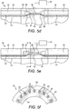
- FIGS 5a to 5f show one way to assemble an ETH PiP sealing arrangement 26 of the invention as shown in Figure 3 .
- the sealing arrangement 26 is characterised by the heating elements 10 being separately embedded in respective bodies of filler 34 in respective longitudinally-extending bores 32.
- the sealing arrangement 26 comprises a cast steel bulkhead 54 that is butt-welded in series with the inner and outer pipes 12, 18. Once welded into that position, the bulkhead 54 becomes integrated with the inner and outer pipes 12, 18 as an extension of the pipe walls.
- the bulkhead 54 comprises concentric inner and outer walls 56, 58 that are spaced to align with the inner and outer pipes 12, 18 respectively and to continue the annulus 16 between them.
- Figures 5a, 5b and 5c show the bulkhead 54 welded to two sections of the inner pipe 12 via the inner wall 54.
- Figures 5d, 5e and 5f show the addition of two sections of the outer pipe 18, welded to the outer wall 58.
- the inner and outer projections 38, 40 extend radially into the annulus 16 from the inner and outer walls 56, 58 respectively.
- the inner and outer walls 56, 58 equate to the inner and outer pipes 12, 18 of the preceding embodiment.
- the inner and outer projections 38, 40 are now joined integrally by a central intermediate ring 60 through which the bores 32 extend longitudinally, leaving walls 36 of the central ring 60 between each adjacent pair of bores 32 as best shown in Figure 5b .
- the bores 32 are connected by a circumferential ring bore 62 that encircles the inner projection 38 and aligns with the port 50.
- the ring bore 62 serves as a manifold that effects fluid communication between the port 50 and all of the bores 32.
- the inner and outer projections 38, 40 each comprise inclined frusto-conical shoulders 44 that extend into the annulus 16 from the respective inner and outer walls 56, 58.
- the shoulders 44 extend to respective ends of the central ring 60, so that the radially-opposed shoulders 44 define longitudinally-tapering annular spaces 64 at each end of the central ring 60.
- the shoulders 44 narrow the annulus 16 from its full width so that the central ring 60, and hence the bores 32 that penetrate the central ring 60, are radially narrower than the full width of the annulus 16.
- the spaces 64 are circumferentially continuous.
- the central ring 60 and the bores 32 could extend into the spaces 64, making the spaces 64 circumferentially discontinuous.
- Figures 5a and 5b show the bulkhead 54 welded to two sections of the inner pipe 12 via the inner wall 54.
- Figure 5c shows one of several longitudinally-extending heating elements 10 laid on the exterior of the inner pipe 12 and threaded through a bore 32 of the bulkhead 54.
- Figure 5c also shows an insulating layer 22 laid around the inner pipe 12 on top of the heating elements 10. Again, the insulating layer 22 is interrupted in the longitudinal direction to accommodate the inner projection 38 of the bulkhead 54. In this example, longitudinally-spaced portions of the insulating layer 22 extend a short distance into the bulkhead 54 to terminate at the base of the shoulders 44.
- Figure 5d and 5e show sections of the outer pipe 18 welded to the bulkhead 54around the corresponding sections of the inner pipe 12 to create the annulus 16, which contains the heating elements 10 and the insulating layer 22.
- Figure 5e shows a liquid or other flowable filler material injected through the port 50, through the ring bore 62 and into the bores 32 under pressure from injection moulding apparatus 52.
- the filler material flows circumferentially from the port 50 to fill the ring bore 62 and then flows axially into the bores 32 around the heating elements 10.
- the port 50 can then be disconnected from the injection moulding apparatus 52 and closed with a welded or threaded filler plug.
- the filler bodies 34 may be confined to the bores 32. Preferably, however, the filler material oozes out of the bores 32 to extend and expand into the tapering annular spaces 64 between the radially-opposed shoulders 44 of the inner and outer projections 38, 40. This better engages the filler bodies 34 with the bores 32.
- Figure 5e shows the filler bodies 34 merging into a circumferentially-continuous mass in the spaces 64, which mass extends to the base of the shoulders 44. There, the filler material meets the insulating layer 22 to maintain continuous thermal insulation along the length of the pipeline.
- injection of filler material can be performed before welding sections of the outer pipe 18 and/or the inner pipe 12 to the bulkhead 54.
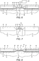
- Figure 6 shows a variant in which the bulkhead 54 is replaced by separate inner and outer rings 66, 68 that are separately butt-welded to the inner and outer pipes 12, 18 respectively.
- Figure 6 shows the inner ring 66 welded between two sections of the inner pipe 12 and the outer ring 68 welded between two sections of the outer pipe 18.
- the inner and outer rings 66, 68 may be machined, forged, cast or moulded.
- inner and outer projections 38, 40 extend radially into the annulus 16 from the inner and outer rings 66, 68 respectively.
- the projections 38, 40 may abut or approach each other radially to define longitudinal bores 32 and a ring bore 62 between them as shown, supplied with liquid filler material from an injection moulding apparatus 52 via a port 50.
- the longitudinal bores 32 and the ring bore 62 may be partially defined by grooves in the inner and outer projections 38, 40 that are brought together in mutual opposition to define the full bores 32, 62. Examples of this approach will be described below in more detail with reference to Figures 11a to 14 .
- the projections 38, 40 may approach each other radially to define a circumferentially-continuous throat region like that shown in Figures 4a to 4g .
- FIG 7 shows that inner and/or outer projections 38, 40 may be separate from and attached to the inner and/or outer pipes 12, 18, for example by welding or bonding.
- the inner and/or outer projections 38, 40 may be machined, forged, cast or moulded. It will be evident to the skilled reader that the inner and/or outer projections 38, 40 could instead be similarly attached to inner and/or outer rings 66, 68 like those shown in Figure 6 or indeed to a bulkhead 54 like that shown in Figures 5a to 5f .
- the inner and outer projections 38, 40 approach each other radially to define a circumferentially-continuous throat region 28 like that shown in Figures 4a to 4g .
- the projections 38, 40 could instead abut or approach each other radially to define longitudinal bores and/or a ring bore between them as in Figures 5a to 5f .
- Figure 7 also shows that a ring bore 62 may be contained in the outer projection 40 or between the outer pipe 18 and the outer projection 40.
- the ring bore 62 is partially defined by circumferential grooves in the outer pipe 18 and the outer projection 40 that are brought together in mutual opposition to define the full ring bore 62.
- the ring bore 62 communicates with the port 50 in the outer pipe 18 to receive liquid filler material.
- the ring bore 62 also communicates with longitudinally-spaced channels 70 to distribute the filler material into the circumferential gap or into longitudinal bores between the inner and outer projections 38, 40.
- the channels 70 may be distributed in angularly-spaced positions around the circumference of the ring bore 62 and may be arranged singly or in groups such as pairs.
- FIG. 8 this shows that it is not essential to introduce liquid filler material via a port 50 as in the preceding embodiments.
- the liquid filler material is introduced via a filler head 72 that is supplied under pressure by a hose or pipe 74 extending along the annulus 16 from an external injection moulding apparatus, which is not shown in this diagram.
- Figure 8 shows the filler head 72 positioned in a section of the annulus 16 on one side of the throat region 28.
- a filler mass 30 of liquid filler material has been forced under pressure from the filler head 72 through the throat region 28 between the inner and outer projections 38, 40.
- the filler mass 30 therefore surrounds and embeds heating elements 10 extending through the throat region 28.
- the filler mass 30 also extends into the section of annulus 16 on the other side of the throat region 28.
- Figure 9 shows that it is not essential for there to be symmetry between inner and outer projections 38, 40 to define the radially-narrowed gap through which the heating elements 10 extend. Indeed, Figure 9 shows that it is not essential for there to be an inner projection 28 at all. Instead, Figure 9 shows the heating elements 10 lying against the straight-sided exterior of the inner pipe 12. A radially-enlarged outer projection 40 is shown facing a longitudinally-extending gap in the insulating layer 22 that lies over the heating elements 10. The heating elements 10 span the gap. An injection moulding apparatus 52 has injected a filler mass 30 through a port 50 to fill the gap, embedding the heating elements 10 and maintaining thermal insulation despite the interruption of the insulating layer 22.
- Liquid or other flowable filler material may be distributed circumferentially around a sealing arrangement by means other than a ring bore.
- Figure 10 shows an annular external channel 76 that is clamped around and sealed to the outer pipe 18.
- the channel 76 communicates with multiple radially-extending ports 50 distributed in angularly-spaced positions around the circumference of the outer pipe 18.
- the channel receives liquid filler material from an injection moulding apparatus 52 and distributes that material to the ports 50.
- the ports 50 then direct the liquid filler material into the gap between the inner and outer projections 38, 40, where it hardens to form a filler mass 30 that embeds the heating elements 10 extending longitudinally through the gap.
- the inner and outer projections 38, 40 may be shaped to define longitudinally-extending bores 32 between them when the projections 38, 40 are brought together to abut or approach each other radially.
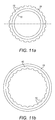
- Figures 11a and 11b show an inner projection 38 on an inner pipe 12 and an outer projection 40 on an outer pipe 18 respectively.
- Matching circumferential arrays of longitudinally-extending angularly-spaced grooves 78 are disposed around the outer face of the inner projection 38 and around the inner face of the outer projection 40.
- the internal diameter of the outer projection 40 slightly exceeds the external diameter of the inner projection 38, so that the inner pipe 12 can fit concentrically within the outer pipe 18 when the inner and outer projections 38, 40 are in longitudinal alignment.
- the grooves 78 are brought together in mutual opposition and radial alignment to define a circumferential array of longitudinally-extending angularly-spaced bores 32 as shown in Figure 12 .
- Figures 13 and 14 show different arrangements to provide for a flow of liquid filler material into the array of bores 32 shown in Figure 12 .
- opposed circumferential grooves 80 encircle the inner and outer projections 38, 40 to define a circumferential ring bore 62 when the inner and outer pipes 12, 18 are brought together.
- a port 50 communicates with the ring bore 62. This is akin to the embodiment shown in Figures 5a to 5f but omits the separate bulkhead 54 of that embodiment.
- the circumferential grooves 80 intersect the longitudinal grooves 78.
- the ring bore 62 defined by longitudinal alignment of the opposed circumferential grooves 80 connects the port 50 to the bores 32, which are defined in turn by radial alignment of the opposed longitudinal grooves 78.
- Figure 14 shows a variant that combines features of Figure 7 with features of Figure 12 .
- the inner and/or outer projections 38, 40 are separate components that are welded to the inner and/or outer pipes 12, 18.
- a ring bore 62 is partially defined by circumferential grooves in the outer pipe 18 and the outer projection 40 that are brought together in mutual opposition.
- the ring bore 62 communicates with a port 50 in the outer pipe 18 to receive liquid filler material.
- the liquid filler material is distributed into the longitudinal bores 32 via channels 70 spaced angularly around the circumference of the ring bore 62.
- Figure 14 also shows, in dotted lines, longitudinally-extending circumferentially-spaced heating elements 10.
- the heating elements 10 lie under an insulating layer 22 that is interrupted by the inner projection 38, where the heating elements 10 can be seen following the longitudinal grooves 78 that form the bores 32 seen in Figure 12 .
- Figure 15 shows inner and outer forged rings 82, 84 respectively of a bulkhead assembly 86.
- the rings 82, 84 are in concentric relation and are attached by butt welds 88 to ends of inner and outer pipes 12, 18 respectively.
- the annulus 16 between the pipes 12, 18 also extends between the rings 82, 84.
- the other ends of the rings 82, 84 are shown in Figure 15 ready for welding to an adjoining pipe length or to an intermediate or termination structure of a pipeline such as a pipeline accessory.
- inner and outer projections 38, 40 that are integral with the rings 82, 84 are spaced longitudinally from each other and overlap radially with each other to interlock.
- Opposed interlocking shoulders 90 of the projections 38, 40 bear against an insulating polymeric spacer ring 92 that fills the longitudinal gap between the confronting shoulders 90.
- the spacer ring 92 provides a mechanical interface between the projections 38, 40 to resist relative longitudinal movement between the inner and outer pipes 12, 18.
- the inner projection 38 is not wholly continuous around the full circumference of the annulus 16, being penetrated by longitudinal bores 32 to accommodate heating elements 10 that are laid on the outside of the inner pipe 12.
- the spacer ring 92 accommodates the heating elements 10 in channels on the radially inner side of the spacer ring 92, aligned with the bores 32. In this way, the heating elements 10 extend through the inner projection 38 and also through the abutting spacer ring 92.
- a polymer is injected into the annulus 16 through a port 94 that penetrates a wall of the outer ring 84.
- the port 94 does not extend through the outer projection 40; instead, the port 94 is longitudinally offset from the outer projection 40. However, the port 94 still communicates with the restriction of the annulus 16 defined by the outer projection 40, so that the sealing mass 30 extends into, and fills all of the remaining space in, that restriction.
- the injected polymer conforms with and seals against the features in the annulus 16 and hardens to form a sealing mass 30.
- the sealing mass 30 separates the sealing function from the function of mechanical resistance, which is performed by the spacer ring 92.
- the sealing mass 30 is shown sealed against one side of the spacer ring 92 and around the heating elements 10.
- the insulating layer 22 is cut back from the spacer ring 92 to leave a gap between the end of the insulating layer 22 and the spacer ring 92 where the inner ring 82 is exposed.
- the sealing mass 30 seals against the exposed surface of the inner ring 82 and the opposed surface of the outer projection 40, and surrounds and embeds the heating elements 10, thus creating a gas-tight seal at an end of the annulus 16.
- either or both of the inner and outer projections may be continuous around the full circumference of the annulus.
- either or both of the inner and outer projections may be discontinuous circumferentially, being interrupted or penetrated by gaps, grooves or holes to accommodate longitudinal heating elements laid on the outside of the inner pipe.
- either or both of the projections may be interrupted circumferentially to the extent that the projection comprises a circumferential array of angularly-spaced teeth.
- Ring bores are only one example of channels that communicate between the or each port and the gaps or bores. Sealing arrangements of the invention may comprise any number of ports or channels leading to the gaps or bores between the inner and outer projections. There may be any number of bores per port or channel; similarly, a channel like a ring bore may communicate with any number of bores.
- a flowable polymer material may be poured through a port in a casting process rather than being injected under pressure.
- Mould plates may be inserted into the annulus to define the boundary of a moulding cavity.
Landscapes
- Engineering & Computer Science (AREA)
- General Engineering & Computer Science (AREA)
- Mechanical Engineering (AREA)
- Geology (AREA)
- Mining & Mineral Resources (AREA)
- Life Sciences & Earth Sciences (AREA)
- Fluid Mechanics (AREA)
- Physics & Mathematics (AREA)
- General Life Sciences & Earth Sciences (AREA)
- Geochemistry & Mineralogy (AREA)
- Environmental & Geological Engineering (AREA)
- Public Health (AREA)
- Health & Medical Sciences (AREA)
- Water Supply & Treatment (AREA)
- Thermal Insulation (AREA)
- Rigid Pipes And Flexible Pipes (AREA)
- Pipe Accessories (AREA)
- Resistance Heating (AREA)
- Gasket Seals (AREA)
- Laying Of Electric Cables Or Lines Outside (AREA)
Claims (20)
- Structure (14) à tuyaux gigognes, chauffée électriquement par traçage, comprenant :une bague intérieure (12, 82) espacée à l'intérieur d'une bague extérieure (18, 84) afin de définir un espace annulaire (16) entre lesdits anneaux ;une restriction (28) à laquelle l'espace annulaire (16) est rétréci radialement par au moins une saillie (38, 40) qui s'étend radialement dans l'espace annulaire (16) depuis au moins l'un desdits anneaux vers l'autre desdits anneaux ;au moins un élément chauffant allongé (10) s'étendant généralement longitudinalement le long de l'espace annulaire (16) et à travers la restriction (28) ;caractérisée en ce que la structure à tuyaux gigognes, chauffée électriquement par traçage comprend au moins une masse d'étanchéité (30) moulée in situ qui ferme radialement la restriction (28) et qui enrobe le ou chaque élément chauffant (10) dans la restriction (28).
- Structure selon la revendication 1, comprenant en outre au moins une couche isolante (22) disposée dans l'espace annulaire (16) sur un côté radialement extérieur du ou de chaque élément chauffant (10), ladite couche isolante (22) est interrompue longitudinalement au niveau de la restriction.
- Procédé selon la revendication 1 ou la revendication 2, dans lequel au moins une saillie (38, 40) qui définit la restriction comprend des épaules inclinées opposées longitudinalement (44) qui définissent des espaces coniques longitudinaux (46) de l'espace annulaire.
- Structure selon la revendication 3, dans laquelle la ou chaque masse d'étanchéité (30) s'étend dans les espaces coniques longitudinaux (46).
- Structure selon l'une quelconque des revendications précédentes, dans laquelle le ou chaque élément chauffant (10) s'étend longitudinalement sur au moins une saillie (38, 40) qui définit la restriction (28), en suivant un contour externe de cette saillie.
- Structure selon l'une quelconque des revendications précédentes, dans laquelle le ou chaque élément chauffant (10) s'étend le long d'une formation femelle qui est prévue dans au moins une saillie (38, 40) définissant la restriction (28) ou qui est prévue entre au moins deux de ces projections.
- Structure selon la revendication 6, dans laquelle la formation femelle est un alésage défini au moins partiellement par une rainure ou par un trou dans ou entre la ou chaque saillie (38, 40).
- Structure selon l'une quelconque des revendications précédentes, dans laquelle la restriction (28) comprend une pluralité d'alésages espacés circonférentiellement (32).
- Structure selon la revendication 7 ou la revendication 8, dans laquelle la restriction (28) comprend en outre au moins une paroi qui ponte la restriction radialement.
- Structure selon l'une quelconque des revendications précédentes, dans laquelle la restriction (28) est continue circonférentiellement autour de la bague intérieure (12, 82), étant partiellement définie par un terrain continu circonférentiellement de la ou de chaque saillie s'étendant radialement.
- Structure selon l'une quelconque des revendications précédentes, dans laquelle la restriction (28) est définie entre une saillie intérieure (38) qui fait saillie radialement vers l'extérieur depuis la bague intérieure (12, 82) et une saillie extérieure (40) qui fait saillie radialement vers l'intérieur depuis la bague extérieure (18, 84).
- Structure selon la revendication 11, dans laquelle :les saillies (38, 40) se font face à travers l'espace annulaire rétréci (16) ; etla ou chaque masse d'étanchéité (30) assure l'étanchéité contre les saillies (38, 40) et autour du ou chaque élément chauffant (10) s'étendant à travers un espace entre les saillies (38, 40), afin de fermer l'espace.
- Structure selon la revendication 11, dans laquelle :les saillies (38, 40) viennent buter ou se rejoignent les unes avec les autres à travers l'espace annulaire (16) ; etune masse d'étanchéité respective (30) assure l'étanchéité autour du ou de chaque élément chauffant (10) s'étendant à travers au moins un trou (32) entre les saillies, afin de fermer le ou chaque trou (32).
- Structure selon l'une quelconque des revendications précédentes, comprenant en outre au moins un canal de remplissage s'étendant circonférentiellement qui communique entre au moins un orifice (50) situé dans la bague extérieure (18, 84) et la restriction (28).
- Procédé d'étanchéification d'un espace annulaire (16) d'une structure (14) à tuyaux gigognes, chauffée électriquement par traçage, ledit espace annulaire (16) est défini entre une bague intérieure (12, 82) et une bague extérieure (18, 84) espacée à l'extérieur de la bague intérieure, le procédé comprenant l'introduction d'un matériau de remplissage fluide pour mouler in situ au moins une masse d'étanchéité (30) qui ferme une restriction (28) au niveau de laquelle l'espace annulaire (16) se réduit radialement et qui intègre au moins un élément chauffant (10) s'étendant généralement dans la longueur par la restriction (28) et le long de l'espace annulaire (16).
- Procédé selon la revendication 15, consistant à placer le ou chaque élément chauffant (10) dans la restriction (28) avant de mouler le matériau de remplissage.
- Procédé selon la revendication 15, comprenant la création de la restriction (28) autour du ou de chaque élément chauffant (10) avant le moulage du matériau de remplissage.
- Procédé selon l'une quelconque des revendications 15 à 17, comprenant l'introduction du matériau de remplissage dans la restriction (28) par la bague extérieure (18, 84).
- Procédé selon la revendication 18, comprenant la distribution circonférentielle du matériau de remplissage avant que le matériau de remplissage n'entre dans la restriction (28).
- Procédé selon l'une quelconque des revendications 15 à 19, comprenant l'extension de la masse d'étanchéité (30) dans au moins un espace (46) de la restriction (28) au niveau duquel l'espace annulaire (16) diminue longitudinalement.
Applications Claiming Priority (3)
| Application Number | Priority Date | Filing Date | Title |
|---|---|---|---|
| GB1501775.9A GB2535145B (en) | 2015-02-03 | 2015-02-03 | Termination bulkheads for subsea pipe-in-pipe systems |
| GB1511632.0A GB2534952B (en) | 2015-02-03 | 2015-07-02 | Sealing arrangements for subsea pipe-in-pipe systems |
| PCT/IB2016/000160 WO2016125010A1 (fr) | 2015-02-03 | 2016-02-02 | Agencements d'étanchéité pour des systèmes sous-marins de conduite à enveloppes multiples |
Publications (2)
| Publication Number | Publication Date |
|---|---|
| EP3254010A1 EP3254010A1 (fr) | 2017-12-13 |
| EP3254010B1 true EP3254010B1 (fr) | 2019-09-25 |
Family
ID=52705682
Family Applications (4)
| Application Number | Title | Priority Date | Filing Date |
|---|---|---|---|
| EP16715604.1A Active EP3254011B1 (fr) | 2015-02-03 | 2016-01-27 | Structures sous-marines de conduites à enveloppes multiples |
| EP16715607.4A Active EP3254012B1 (fr) | 2015-02-03 | 2016-01-27 | Cloisons de terminaison pour systèmes sous-marins de conduites à enveloppes multiples |
| EP16714518.4A Active EP3254010B1 (fr) | 2015-02-03 | 2016-02-02 | Agencements d'étanchéité pour des systèmes sous-marins de conduite à enveloppes multiples |
| EP16713976.5A Active EP3254009B8 (fr) | 2015-02-03 | 2016-02-02 | Ensembles d'étanchéité pour systèmes de conduites sous-marines à double enveloppe |
Family Applications Before (2)
| Application Number | Title | Priority Date | Filing Date |
|---|---|---|---|
| EP16715604.1A Active EP3254011B1 (fr) | 2015-02-03 | 2016-01-27 | Structures sous-marines de conduites à enveloppes multiples |
| EP16715607.4A Active EP3254012B1 (fr) | 2015-02-03 | 2016-01-27 | Cloisons de terminaison pour systèmes sous-marins de conduites à enveloppes multiples |
Family Applications After (1)
| Application Number | Title | Priority Date | Filing Date |
|---|---|---|---|
| EP16713976.5A Active EP3254009B8 (fr) | 2015-02-03 | 2016-02-02 | Ensembles d'étanchéité pour systèmes de conduites sous-marines à double enveloppe |
Country Status (6)
| Country | Link |
|---|---|
| US (4) | US10577871B2 (fr) |
| EP (4) | EP3254011B1 (fr) |
| AU (4) | AU2016214075B2 (fr) |
| BR (4) | BR112017015690B1 (fr) |
| GB (3) | GB2535145B (fr) |
| WO (4) | WO2016125024A1 (fr) |
Families Citing this family (31)
| Publication number | Priority date | Publication date | Assignee | Title |
|---|---|---|---|---|
| GB2535145B (en) * | 2015-02-03 | 2017-10-18 | Acergy France SAS | Termination bulkheads for subsea pipe-in-pipe systems |
| DE102016000192B3 (de) * | 2016-01-13 | 2017-01-19 | A. Kayser Automotive Systems Gmbh | Beheizbare Medienleitung |
| GB2546749B (en) * | 2016-01-26 | 2019-01-09 | Nylacast Ltd | Spacer for a double walled marine conduit |
| CN106704733B (zh) * | 2017-01-23 | 2018-09-18 | 中国铁道科学研究院铁道建筑研究所 | 排水管件及其在铁路建筑中的应用 |
| BR112019017720A2 (pt) * | 2017-02-28 | 2020-03-31 | Sandvik Intellectual Property Ab | Uma estrutura de tubo com um sensor protegido e método para fabricação de uma estrutura de tubo com um sensor protegido |
| EP3421715A1 (fr) * | 2017-06-30 | 2019-01-02 | Nexans | Système de chauffage électrique direct étendu |
| US11231137B2 (en) * | 2018-05-14 | 2022-01-25 | Oceaneering International, Inc. | Subsea flowline blockage remediation using external heating device |
| IT201800006717A1 (it) * | 2018-06-27 | 2019-12-27 | Metodo di monitoraggio di una condotta continua, dispositivo di monitoraggio e assieme comprendente detto dispositivo | |
| US11287067B2 (en) * | 2018-06-27 | 2022-03-29 | The Boeing Company | Ferrule coupling for joining ducts together |
| CN109027497B (zh) * | 2018-08-29 | 2021-04-13 | 西安石油大学 | 一种石油化工流体换热用螺旋流减阻流体输运管道 |
| CN109282089B (zh) * | 2018-11-30 | 2021-04-30 | 江苏洁润管业有限公司 | 一种双通道复合管 |
| RU202636U1 (ru) * | 2019-10-23 | 2021-03-01 | Федеральное государственное бюджетное учреждение науки Федеральный исследовательский центр "Якутский научный центр Сибирского отделения Российской академии наук" | Устройство для защиты газопроводов от механических повреждений |
| EP3819530B1 (fr) * | 2019-11-07 | 2023-06-07 | GammaSwiss SA | Système de chauffage électrique de pipeline |
| GB2590611B (en) | 2019-12-12 | 2022-06-01 | Subsea 7 Ltd | Mitigation of buckling in subsea pipe-in-pipe systems |
| GB2590453B (en) | 2019-12-18 | 2022-06-01 | Subsea 7 Ltd | Spooling and installing trace-heated pipelines of pipe-in-pipe configuration |
| CN111456682B (zh) * | 2020-04-20 | 2021-06-22 | 大庆市鹤翔机械有限公司 | 井下油管与抽油杆加热装置 |
| CN111503405A (zh) * | 2020-05-15 | 2020-08-07 | 朱昀 | 一种管道伴热电缆 |
| WO2022031791A1 (fr) * | 2020-08-04 | 2022-02-10 | Micropen Technologies Corporation | Ensembles conduit de fluide et systèmes de transport de fluide |
| CN112066100B (zh) * | 2020-08-28 | 2024-03-12 | 李宛芸 | 一种涡轮式石油管道 |
| US11608940B2 (en) * | 2020-09-01 | 2023-03-21 | Saudi Arabian Oil Company | Passive thermal diode for transportation pipelines using contact switch based on polymer thermal expansion (PTE-PTD) |
| US11402051B2 (en) | 2020-09-01 | 2022-08-02 | Saudi Arabian Oil Company | System for installing insulation sleeves on pipelines |
| US11359759B2 (en) * | 2020-09-01 | 2022-06-14 | Saudi Arabian Oil Company | Passive thermal diode for transportation pipelines using contact switch based on shape memory polymer (SMP-PTD) |
| EP4229321B1 (fr) | 2020-10-16 | 2024-10-02 | SAIPEM S.p.A. | Système pour transporter un fluide |
| CN112983328B (zh) * | 2021-02-18 | 2021-11-19 | 江苏腾龙石化机械有限公司 | 一种防冻石油井口 |
| CA3115685C (fr) * | 2021-04-21 | 2022-02-15 | Integrity Products And Supplies Inc. | Systeme d`entretoise d`isolation de conduite |
| US20230023662A1 (en) * | 2021-07-26 | 2023-01-26 | Motivo Group, Inc. | Chemical Sewer Pipe Liner System and Method |
| US11548784B1 (en) | 2021-10-26 | 2023-01-10 | Saudi Arabian Oil Company | Treating sulfur dioxide containing stream by acid aqueous absorption |
| US12116326B2 (en) | 2021-11-22 | 2024-10-15 | Saudi Arabian Oil Company | Conversion of hydrogen sulfide and carbon dioxide into hydrocarbons using non-thermal plasma and a catalyst |
| US12179129B2 (en) | 2021-12-14 | 2024-12-31 | Saudi Arabian Oil Company | Synergetic solvent for crude oil emulsion breakers |
| US11926799B2 (en) | 2021-12-14 | 2024-03-12 | Saudi Arabian Oil Company | 2-iso-alkyl-2-(4-hydroxyphenyl)propane derivatives used as emulsion breakers for crude oil |
| WO2024206626A2 (fr) * | 2023-03-30 | 2024-10-03 | Damico Joseph V Iii | Système et procédé de traçage thermique |
Citations (1)
| Publication number | Priority date | Publication date | Assignee | Title |
|---|---|---|---|---|
| WO2016062319A1 (fr) * | 2014-10-20 | 2016-04-28 | National Oilwell Varco Denmark I/S | Ensemble comprenant un embout et un tuyau flexible non lié |
Family Cites Families (70)
| Publication number | Priority date | Publication date | Assignee | Title |
|---|---|---|---|---|
| USRE16523E (en) * | 1927-01-04 | and the like and method of and apparatus for making the same | ||
| US2440245A (en) * | 1944-03-13 | 1948-04-27 | Standard Telephones Cables Ltd | Cooling of high-temperature bodies |
| US2720267A (en) * | 1949-12-12 | 1955-10-11 | Cicero C Brown | Sealing assemblies for well packers |
| US3407835A (en) * | 1965-06-21 | 1968-10-29 | Trans Continental Electronics | Insulated heating or cooling system for elongated pipes |
| US3374308A (en) * | 1966-09-12 | 1968-03-19 | Res Molding Inc | Conduit insulating spacer |
| JPS4929027B1 (fr) | 1968-08-08 | 1974-07-31 | ||
| US3540487A (en) * | 1968-12-20 | 1970-11-17 | Eastman Kodak Co | Spacer for preinsulated pipe |
| JPS4823928B1 (fr) * | 1969-03-26 | 1973-07-17 | ||
| CA926377A (en) * | 1970-08-25 | 1973-05-15 | Harold S. Chapman | Dual concentric drillpipe |
| US3971416A (en) * | 1974-08-16 | 1976-07-27 | Thermon Manufacturing Company | Preinsulated pipe assembly and pipeline |
| US3964754A (en) * | 1975-05-19 | 1976-06-22 | Nishiyama Gomu Kabushiki Kaisha | Device for sealing the end of sheath pipe |
| GB1579670A (en) * | 1976-05-21 | 1980-11-19 | Wavin Bv | Pipes |
| DE2647235C2 (de) * | 1976-10-20 | 1986-11-20 | Dieter Spezial-Isolierungen GmbH & Co., 7401 Nehren | Distanzhalter für durch Schutzrohre hindurchgeführte Rohre |
| US4194536A (en) * | 1976-12-09 | 1980-03-25 | Eaton Corporation | Composite tubing product |
| DE2823101C2 (de) * | 1978-05-26 | 1982-08-05 | Kabel- und Metallwerke Gutehoffnungshütte AG, 3000 Hannover | Verfahren zur Herstellung wärmeisolierter Leitungsrohre |
| DE2836957A1 (de) * | 1978-08-24 | 1980-03-13 | Kabel Metallwerke Ghh | Waermeisoliertes leitungsrohr |
| NL177516C (nl) * | 1978-09-12 | 1985-10-01 | Pidou Bv | Afdichtmanchet. |
| DE3010437A1 (de) * | 1980-03-19 | 1981-09-24 | Kabel- und Metallwerke Gutehoffnungshütte AG, 3000 Hannover | Verfahren zur kontinuierlichen herstellung von abstandshaltern fuer koaxiale rohrsysteme |
| IT1150849B (it) | 1982-04-20 | 1986-12-17 | Snam Progetti | Tubazione isolata termicamente per la costruzione di condotte subacquee |
| IT1176382B (it) | 1984-07-09 | 1987-08-18 | Snam Progetti | Tubazione perfezionata per la costruzione di condotte isolate termicamente e procedimento per detta costruzione |
| US5803127A (en) * | 1985-12-16 | 1998-09-08 | R & R Precision Corp. | Coaxial piping systems |
| CH672014A5 (fr) * | 1986-08-29 | 1989-10-13 | Fischer Ag Georg | |
| US4751947A (en) * | 1987-06-30 | 1988-06-21 | Landers Phillip G | System for plugging conduits |
| US5069255A (en) * | 1988-07-29 | 1991-12-03 | Power Lone Star, Inc. | Pipeline casing insulator |
| DE3931058C1 (en) | 1989-09-18 | 1990-07-26 | Jung Ohg, 6232 Bad Soden, De | Pipeline laying method - outer pipe casings are welded before inner flow pipes, and latter pushed into already laid pipe casing |
| US4984633A (en) | 1989-10-20 | 1991-01-15 | Weatherford U.S., Inc. | Nozzle effect protectors, centralizers, and stabilizers and related methods |
| US5071140A (en) * | 1990-01-02 | 1991-12-10 | Federico Quevedo Del Rio | Self-pressurized gasket seal |
| US5259651A (en) | 1991-04-04 | 1993-11-09 | Sharp Bruce R | Double wall fittings for use with double wall pipeline systems |
| FR2699979B1 (fr) * | 1992-12-29 | 1995-02-03 | Courant Ets Sa | Conduit multicouche et filière pour sa fabrication. |
| US5390961A (en) * | 1993-04-28 | 1995-02-21 | Thermon Manufacturing Company | Dual wall thermally insulated conduit including skin effect heat tracing pipes |
| US5497809A (en) * | 1994-01-05 | 1996-03-12 | Wolf; Lawrence W. | Vented bending sleeves for coaxial tubing systems |
| JPH09189382A (ja) * | 1996-01-10 | 1997-07-22 | Usui Internatl Ind Co Ltd | アイジョイントと細径金属管との接続構造およびその連接方法 |
| US6279654B1 (en) * | 1996-10-04 | 2001-08-28 | Donald E. Mosing | Method and multi-purpose apparatus for dispensing and circulating fluid in wellbore casing |
| US6202656B1 (en) * | 1998-03-03 | 2001-03-20 | Applied Materials, Inc. | Uniform heat trace and secondary containment for delivery lines for processing system |
| US6634388B1 (en) * | 1998-07-22 | 2003-10-21 | Safetyliner Systems, Llc | Annular fluid manipulation in lined tubular systems |
| AU756204B2 (en) * | 1998-07-28 | 2003-01-09 | Safetyliner Systems, Llc | Enhancement of profiled tubular lining systems by channel augmentation |
| FR2795807B1 (fr) | 1999-07-02 | 2001-07-27 | Coflexip | Dispositif limiteur de propagation d'une deformation dans un tube a double paroi |
| NO994044D0 (no) * | 1999-08-20 | 1999-08-20 | Kvaerner Oilfield Prod As | Anordning og fremgangsmÕter ved produksjons-/injeksjonsrörledning |
| DE10018380A1 (de) * | 2000-04-13 | 2001-10-18 | Scc Special Comm Cables Gmbh | Kanal- oder Rohrsystem und Verfahren zur Sanierung eines Kanal- oder Rohrsystems und zur Installation eines Kabels oder Leerrohrs in einem Kanal- oder Rohrsystem sowie Vorrichtung zur Installation eines Kabels oder Leerrohrs |
| GB0019502D0 (en) * | 2000-08-08 | 2000-09-27 | Oil States Ind Uk Ltd | Pipe assembly |
| US6564011B1 (en) | 2000-08-23 | 2003-05-13 | Fmc Technologies, Inc. | Self-regulating heat source for subsea equipment |
| US6739803B2 (en) * | 2001-07-20 | 2004-05-25 | Shell Oil Company | Method of installation of electrically heated pipe-in-pipe subsea pipeline |
| FR2828924B1 (fr) * | 2001-08-27 | 2003-10-31 | Coflexip | Conduite flexible pour le transport d'un fluide |
| GB0125148D0 (en) | 2001-10-19 | 2001-12-12 | Coflexip | Bulkhead assembly for use in pipe-in-pipe systems |
| WO2003102455A1 (fr) | 2002-05-31 | 2003-12-11 | Technip France Sa | Systeme d'etancheite |
| GB2391281B (en) | 2002-07-26 | 2005-11-02 | Coflexip Stena Offshore Ltd | Seal assembly |
| US20050212285A1 (en) * | 2004-03-29 | 2005-09-29 | Ope International, L.P. | Dual-walled piping system and methods |
| GB0501056D0 (en) | 2005-01-18 | 2005-02-23 | Downhole Products Plc | Centraliser |
| GB0523599D0 (en) | 2005-11-19 | 2005-12-28 | Nylacast Ltd | Improved spacer |
| GB2444060B (en) * | 2006-11-21 | 2008-12-17 | Swelltec Ltd | Downhole apparatus and method |
| BRPI0605003B1 (pt) | 2006-11-30 | 2020-04-22 | Petroleo Brasileiro S.A. - Petrobras | dispositivo para vedação de anular de duto "pipe-in-pipe" |
| FR2918149B1 (fr) | 2007-06-29 | 2009-09-25 | Inst Francais Du Petrole | Conduite renforcee a deux enveloppes et methode de fabrication. |
| US20090152817A1 (en) * | 2007-12-14 | 2009-06-18 | Schlumberger Technology Corporation | Energized dynamic seal used in oil well equipment |
| WO2009083937A2 (fr) * | 2007-12-27 | 2009-07-09 | Acergy France Sa | Conduites isolées et leurs procédés de construction et d'installation |
| CA2715647C (fr) * | 2008-02-19 | 2013-10-01 | Weatherford/Lamb, Inc. | Garniture d'etancheite expansible |
| CN103148293B (zh) * | 2009-01-27 | 2015-07-29 | 株式会社久保田 | 管接头 |
| US20120312560A1 (en) * | 2011-06-07 | 2012-12-13 | Board Of Regents, The University Of Texas System | Sealing apparatus and method for forming a seal in a subterranean wellbore |
| FR2991024B1 (fr) * | 2012-05-25 | 2014-06-20 | Itp Sa | Procede de pose d'un conduit de transport d'un fluide par troncons equipes chacun d'un systeme de chauffage electrique |
| MY161019A (en) * | 2011-07-11 | 2017-03-31 | Itp Sa | Electrical heating system for a section of fluid transport pipe,section and pipe equipped with such an electrical heating system |
| US8443680B2 (en) | 2011-07-13 | 2013-05-21 | J. Ray Mcdermott, S.A. | Pipe reel load simulator |
| GB2493545B (en) * | 2011-08-11 | 2013-09-11 | Technip France | T-piece preformer |
| GB2494180B (en) * | 2011-09-02 | 2013-09-04 | Technip France | A connector arrangement for pipe-in-pipe pipeline |
| EP2631421A1 (fr) * | 2012-02-22 | 2013-08-28 | Quantum Technologie GmbH | Pipeline chauffant pour pétrole brut |
| NO334988B1 (no) * | 2012-03-14 | 2014-08-18 | Purapipe Holding Ltd | Flerlagsrør i polymermateriale, apparat for framstilling av flerlagsrøret og framgangsmåte for samme |
| MY176920A (en) * | 2012-06-25 | 2020-08-26 | Kubota Kk | Sealing material, pressing ring, joint, and valve |
| FR2994593B1 (fr) | 2012-08-20 | 2014-09-05 | Technip France | Raccord intermediaire de connexion d'elements de conduite rigide de transport de fluide, reseau de conduites et procede d'assemblage associes |
| US8833440B1 (en) * | 2013-11-14 | 2014-09-16 | Douglas Ray Dicksinson | High-temperature heat, steam and hot-fluid viscous hydrocarbon production and pumping tool |
| DE102014105555A1 (de) * | 2014-04-17 | 2015-10-22 | Brugg Rohr Ag, Holding | Anschlussverbindung für Wellrohre |
| FR3021385B1 (fr) | 2014-05-23 | 2017-01-20 | Itp Sa | Troncon pour un conduit double enveloppe monte par vissage thermiquement isole et chauffe et son procede de mise en oeuvre |
| GB2535145B (en) | 2015-02-03 | 2017-10-18 | Acergy France SAS | Termination bulkheads for subsea pipe-in-pipe systems |
-
2015
- 2015-02-03 GB GB1501775.9A patent/GB2535145B/en active Active
- 2015-03-30 GB GB1505466.1A patent/GB2535240B/en active Active
- 2015-07-02 GB GB1511632.0A patent/GB2534952B/en active Active
-
2016
- 2016-01-27 US US15/547,702 patent/US10577871B2/en active Active
- 2016-01-27 US US15/547,762 patent/US10435953B2/en active Active
- 2016-01-27 BR BR112017015690-3A patent/BR112017015690B1/pt active IP Right Grant
- 2016-01-27 AU AU2016214075A patent/AU2016214075B2/en active Active
- 2016-01-27 BR BR112017016294-6A patent/BR112017016294B1/pt active IP Right Grant
- 2016-01-27 EP EP16715604.1A patent/EP3254011B1/fr active Active
- 2016-01-27 EP EP16715607.4A patent/EP3254012B1/fr active Active
- 2016-01-27 WO PCT/IB2016/000280 patent/WO2016125024A1/fr not_active Ceased
- 2016-01-27 AU AU2016214078A patent/AU2016214078B2/en active Active
- 2016-01-27 WO PCT/IB2016/000238 patent/WO2016125021A1/fr not_active Ceased
- 2016-02-02 BR BR112017015179-0A patent/BR112017015179B1/pt active IP Right Grant
- 2016-02-02 EP EP16714518.4A patent/EP3254010B1/fr active Active
- 2016-02-02 US US15/547,798 patent/US10344539B2/en active Active
- 2016-02-02 WO PCT/IB2016/000163 patent/WO2016125011A1/fr not_active Ceased
- 2016-02-02 AU AU2016214065A patent/AU2016214065B2/en active Active
- 2016-02-02 EP EP16713976.5A patent/EP3254009B8/fr active Active
- 2016-02-02 AU AU2016214118A patent/AU2016214118B2/en active Active
- 2016-02-02 WO PCT/IB2016/000160 patent/WO2016125010A1/fr not_active Ceased
- 2016-02-02 US US15/547,791 patent/US10352107B2/en active Active
- 2016-02-02 BR BR112017015787-0A patent/BR112017015787B1/pt active IP Right Grant
Patent Citations (1)
| Publication number | Priority date | Publication date | Assignee | Title |
|---|---|---|---|---|
| WO2016062319A1 (fr) * | 2014-10-20 | 2016-04-28 | National Oilwell Varco Denmark I/S | Ensemble comprenant un embout et un tuyau flexible non lié |
Also Published As
Similar Documents
| Publication | Publication Date | Title |
|---|---|---|
| EP3254010B1 (fr) | Agencements d'étanchéité pour des systèmes sous-marins de conduite à enveloppes multiples | |
| JP2009540244A (ja) | フレキシブルパイプ用継手の組立方法 | |
| JP2009540245A (ja) | フレキシブルパイプ用の継手装置 | |
| US9909706B2 (en) | Branch structures of electrically-heated pipe-in-pipe flowlines | |
| US11781700B2 (en) | Insulating inserts for field joints of coated rigid pipelines | |
| US10309162B2 (en) | Techniques for coating pipes |
Legal Events
| Date | Code | Title | Description |
|---|---|---|---|
| STAA | Information on the status of an ep patent application or granted ep patent |
Free format text: STATUS: THE INTERNATIONAL PUBLICATION HAS BEEN MADE |
|
| PUAI | Public reference made under article 153(3) epc to a published international application that has entered the european phase |
Free format text: ORIGINAL CODE: 0009012 |
|
| STAA | Information on the status of an ep patent application or granted ep patent |
Free format text: STATUS: REQUEST FOR EXAMINATION WAS MADE |
|
| 17P | Request for examination filed |
Effective date: 20170721 |
|
| AK | Designated contracting states |
Kind code of ref document: A1 Designated state(s): AL AT BE BG CH CY CZ DE DK EE ES FI FR GB GR HR HU IE IS IT LI LT LU LV MC MK MT NL NO PL PT RO RS SE SI SK SM TR |
|
| AX | Request for extension of the european patent |
Extension state: BA ME |
|
| DAV | Request for validation of the european patent (deleted) | ||
| DAX | Request for extension of the european patent (deleted) | ||
| GRAP | Despatch of communication of intention to grant a patent |
Free format text: ORIGINAL CODE: EPIDOSNIGR1 |
|
| STAA | Information on the status of an ep patent application or granted ep patent |
Free format text: STATUS: GRANT OF PATENT IS INTENDED |
|
| RIC1 | Information provided on ipc code assigned before grant |
Ipc: E21B 17/00 20060101ALI20180924BHEP Ipc: F16L 53/30 20180101ALI20180924BHEP Ipc: F17D 1/18 20060101ALI20180924BHEP Ipc: F16L 1/16 20060101ALI20180924BHEP Ipc: F16L 9/18 20060101ALI20180924BHEP Ipc: F16L 7/00 20060101ALI20180924BHEP Ipc: E21B 43/013 20060101ALI20180924BHEP Ipc: H05B 3/42 20060101AFI20180924BHEP Ipc: F16L 59/065 20060101ALI20180924BHEP Ipc: F16L 9/19 20060101ALI20180924BHEP Ipc: E21B 36/04 20060101ALI20180924BHEP Ipc: F16L 53/38 20180101ALI20180924BHEP Ipc: F16L 7/02 20060101ALI20180924BHEP Ipc: E21B 36/00 20060101ALI20180924BHEP Ipc: F16L 1/12 20060101ALI20180924BHEP Ipc: E21B 43/01 20060101ALI20180924BHEP |
|
| INTG | Intention to grant announced |
Effective date: 20181019 |
|
| RIC1 | Information provided on ipc code assigned before grant |
Ipc: F16L 9/18 20060101ALI20180924BHEP Ipc: H05B 3/42 20060101AFI20180924BHEP Ipc: F16L 9/19 20060101ALI20180924BHEP Ipc: F16L 7/02 20060101ALI20180924BHEP Ipc: F16L 53/38 20180101ALI20180924BHEP Ipc: F17D 1/18 20060101ALI20180924BHEP Ipc: E21B 17/00 20060101ALI20180924BHEP Ipc: F16L 7/00 20060101ALI20180924BHEP Ipc: F16L 53/30 20180101ALI20180924BHEP Ipc: E21B 36/04 20060101ALI20180924BHEP Ipc: F16L 1/12 20060101ALI20180924BHEP Ipc: F16L 1/16 20060101ALI20180924BHEP Ipc: F16L 59/065 20060101ALI20180924BHEP Ipc: E21B 43/013 20060101ALI20180924BHEP Ipc: E21B 43/01 20060101ALI20180924BHEP Ipc: E21B 36/00 20060101ALI20180924BHEP |
|
| GRAJ | Information related to disapproval of communication of intention to grant by the applicant or resumption of examination proceedings by the epo deleted |
Free format text: ORIGINAL CODE: EPIDOSDIGR1 |
|
| STAA | Information on the status of an ep patent application or granted ep patent |
Free format text: STATUS: REQUEST FOR EXAMINATION WAS MADE |
|
| REG | Reference to a national code |
Ref country code: DE Ref legal event code: R079 Ref document number: 602016021208 Country of ref document: DE Free format text: PREVIOUS MAIN CLASS: F16L0001160000 Ipc: F17D0003010000 |
|
| GRAP | Despatch of communication of intention to grant a patent |
Free format text: ORIGINAL CODE: EPIDOSNIGR1 |
|
| STAA | Information on the status of an ep patent application or granted ep patent |
Free format text: STATUS: GRANT OF PATENT IS INTENDED |
|
| INTC | Intention to grant announced (deleted) | ||
| RIC1 | Information provided on ipc code assigned before grant |
Ipc: F16L 7/02 20060101ALI20190306BHEP Ipc: F16L 9/19 20060101ALI20190306BHEP Ipc: F16L 7/00 20060101ALI20190306BHEP Ipc: H05B 3/42 20060101ALI20190306BHEP Ipc: E21B 43/013 20060101ALI20190306BHEP Ipc: F17D 1/18 20060101ALI20190306BHEP Ipc: F16L 53/38 20180101ALI20190306BHEP Ipc: E21B 36/00 20060101ALI20190306BHEP Ipc: F16L 53/30 20180101ALI20190306BHEP Ipc: E21B 17/00 20060101ALI20190306BHEP Ipc: E21B 43/01 20060101ALI20190306BHEP Ipc: E21B 36/04 20060101ALI20190306BHEP Ipc: F16L 9/18 20060101ALI20190306BHEP Ipc: F16L 1/16 20060101ALI20190306BHEP Ipc: F17D 3/01 20060101AFI20190306BHEP Ipc: F16L 59/065 20060101ALI20190306BHEP |
|
| INTG | Intention to grant announced |
Effective date: 20190321 |
|
| GRAS | Grant fee paid |
Free format text: ORIGINAL CODE: EPIDOSNIGR3 |
|
| GRAA | (expected) grant |
Free format text: ORIGINAL CODE: 0009210 |
|
| STAA | Information on the status of an ep patent application or granted ep patent |
Free format text: STATUS: THE PATENT HAS BEEN GRANTED |
|
| RIN1 | Information on inventor provided before grant (corrected) |
Inventor name: ROUSSEAU, HENRI Inventor name: DELAUNAY, NATHALIE Inventor name: GEROMETTA, GERALD |
|
| AK | Designated contracting states |
Kind code of ref document: B1 Designated state(s): AL AT BE BG CH CY CZ DE DK EE ES FI FR GB GR HR HU IE IS IT LI LT LU LV MC MK MT NL NO PL PT RO RS SE SI SK SM TR |
|
| REG | Reference to a national code |
Ref country code: GB Ref legal event code: FG4D |
|
| REG | Reference to a national code |
Ref country code: CH Ref legal event code: EP |
|
| REG | Reference to a national code |
Ref country code: AT Ref legal event code: REF Ref document number: 1184157 Country of ref document: AT Kind code of ref document: T Effective date: 20191015 |
|
| REG | Reference to a national code |
Ref country code: IE Ref legal event code: FG4D |
|
| REG | Reference to a national code |
Ref country code: DE Ref legal event code: R096 Ref document number: 602016021208 Country of ref document: DE |
|
| REG | Reference to a national code |
Ref country code: NL Ref legal event code: MP Effective date: 20190925 |
|
| PG25 | Lapsed in a contracting state [announced via postgrant information from national office to epo] |
Ref country code: BG Free format text: LAPSE BECAUSE OF FAILURE TO SUBMIT A TRANSLATION OF THE DESCRIPTION OR TO PAY THE FEE WITHIN THE PRESCRIBED TIME-LIMIT Effective date: 20191225 Ref country code: LT Free format text: LAPSE BECAUSE OF FAILURE TO SUBMIT A TRANSLATION OF THE DESCRIPTION OR TO PAY THE FEE WITHIN THE PRESCRIBED TIME-LIMIT Effective date: 20190925 Ref country code: HR Free format text: LAPSE BECAUSE OF FAILURE TO SUBMIT A TRANSLATION OF THE DESCRIPTION OR TO PAY THE FEE WITHIN THE PRESCRIBED TIME-LIMIT Effective date: 20190925 Ref country code: SE Free format text: LAPSE BECAUSE OF FAILURE TO SUBMIT A TRANSLATION OF THE DESCRIPTION OR TO PAY THE FEE WITHIN THE PRESCRIBED TIME-LIMIT Effective date: 20190925 Ref country code: FI Free format text: LAPSE BECAUSE OF FAILURE TO SUBMIT A TRANSLATION OF THE DESCRIPTION OR TO PAY THE FEE WITHIN THE PRESCRIBED TIME-LIMIT Effective date: 20190925 |
|
| REG | Reference to a national code |
Ref country code: NO Ref legal event code: T2 Effective date: 20190925 |
|
| REG | Reference to a national code |
Ref country code: LT Ref legal event code: MG4D |
|
| PG25 | Lapsed in a contracting state [announced via postgrant information from national office to epo] |
Ref country code: RS Free format text: LAPSE BECAUSE OF FAILURE TO SUBMIT A TRANSLATION OF THE DESCRIPTION OR TO PAY THE FEE WITHIN THE PRESCRIBED TIME-LIMIT Effective date: 20190925 Ref country code: GR Free format text: LAPSE BECAUSE OF FAILURE TO SUBMIT A TRANSLATION OF THE DESCRIPTION OR TO PAY THE FEE WITHIN THE PRESCRIBED TIME-LIMIT Effective date: 20191226 Ref country code: LV Free format text: LAPSE BECAUSE OF FAILURE TO SUBMIT A TRANSLATION OF THE DESCRIPTION OR TO PAY THE FEE WITHIN THE PRESCRIBED TIME-LIMIT Effective date: 20190925 |
|
| REG | Reference to a national code |
Ref country code: AT Ref legal event code: MK05 Ref document number: 1184157 Country of ref document: AT Kind code of ref document: T Effective date: 20190925 |
|
| PG25 | Lapsed in a contracting state [announced via postgrant information from national office to epo] |
Ref country code: IT Free format text: LAPSE BECAUSE OF FAILURE TO SUBMIT A TRANSLATION OF THE DESCRIPTION OR TO PAY THE FEE WITHIN THE PRESCRIBED TIME-LIMIT Effective date: 20190925 Ref country code: RO Free format text: LAPSE BECAUSE OF FAILURE TO SUBMIT A TRANSLATION OF THE DESCRIPTION OR TO PAY THE FEE WITHIN THE PRESCRIBED TIME-LIMIT Effective date: 20190925 Ref country code: PT Free format text: LAPSE BECAUSE OF FAILURE TO SUBMIT A TRANSLATION OF THE DESCRIPTION OR TO PAY THE FEE WITHIN THE PRESCRIBED TIME-LIMIT Effective date: 20200127 Ref country code: EE Free format text: LAPSE BECAUSE OF FAILURE TO SUBMIT A TRANSLATION OF THE DESCRIPTION OR TO PAY THE FEE WITHIN THE PRESCRIBED TIME-LIMIT Effective date: 20190925 Ref country code: AT Free format text: LAPSE BECAUSE OF FAILURE TO SUBMIT A TRANSLATION OF THE DESCRIPTION OR TO PAY THE FEE WITHIN THE PRESCRIBED TIME-LIMIT Effective date: 20190925 Ref country code: NL Free format text: LAPSE BECAUSE OF FAILURE TO SUBMIT A TRANSLATION OF THE DESCRIPTION OR TO PAY THE FEE WITHIN THE PRESCRIBED TIME-LIMIT Effective date: 20190925 Ref country code: PL Free format text: LAPSE BECAUSE OF FAILURE TO SUBMIT A TRANSLATION OF THE DESCRIPTION OR TO PAY THE FEE WITHIN THE PRESCRIBED TIME-LIMIT Effective date: 20190925 Ref country code: ES Free format text: LAPSE BECAUSE OF FAILURE TO SUBMIT A TRANSLATION OF THE DESCRIPTION OR TO PAY THE FEE WITHIN THE PRESCRIBED TIME-LIMIT Effective date: 20190925 Ref country code: AL Free format text: LAPSE BECAUSE OF FAILURE TO SUBMIT A TRANSLATION OF THE DESCRIPTION OR TO PAY THE FEE WITHIN THE PRESCRIBED TIME-LIMIT Effective date: 20190925 |
|
| PG25 | Lapsed in a contracting state [announced via postgrant information from national office to epo] |
Ref country code: IS Free format text: LAPSE BECAUSE OF FAILURE TO SUBMIT A TRANSLATION OF THE DESCRIPTION OR TO PAY THE FEE WITHIN THE PRESCRIBED TIME-LIMIT Effective date: 20200224 Ref country code: SK Free format text: LAPSE BECAUSE OF FAILURE TO SUBMIT A TRANSLATION OF THE DESCRIPTION OR TO PAY THE FEE WITHIN THE PRESCRIBED TIME-LIMIT Effective date: 20190925 Ref country code: SM Free format text: LAPSE BECAUSE OF FAILURE TO SUBMIT A TRANSLATION OF THE DESCRIPTION OR TO PAY THE FEE WITHIN THE PRESCRIBED TIME-LIMIT Effective date: 20190925 Ref country code: CZ Free format text: LAPSE BECAUSE OF FAILURE TO SUBMIT A TRANSLATION OF THE DESCRIPTION OR TO PAY THE FEE WITHIN THE PRESCRIBED TIME-LIMIT Effective date: 20190925 |
|
| REG | Reference to a national code |
Ref country code: DE Ref legal event code: R097 Ref document number: 602016021208 Country of ref document: DE |
|
| PG2D | Information on lapse in contracting state deleted |
Ref country code: IS |
|
| PG25 | Lapsed in a contracting state [announced via postgrant information from national office to epo] |
Ref country code: DK Free format text: LAPSE BECAUSE OF FAILURE TO SUBMIT A TRANSLATION OF THE DESCRIPTION OR TO PAY THE FEE WITHIN THE PRESCRIBED TIME-LIMIT Effective date: 20190925 Ref country code: IS Free format text: LAPSE BECAUSE OF FAILURE TO SUBMIT A TRANSLATION OF THE DESCRIPTION OR TO PAY THE FEE WITHIN THE PRESCRIBED TIME-LIMIT Effective date: 20200126 |
|
| PLBE | No opposition filed within time limit |
Free format text: ORIGINAL CODE: 0009261 |
|
| STAA | Information on the status of an ep patent application or granted ep patent |
Free format text: STATUS: NO OPPOSITION FILED WITHIN TIME LIMIT |
|
| REG | Reference to a national code |
Ref country code: DE Ref legal event code: R119 Ref document number: 602016021208 Country of ref document: DE |
|
| 26N | No opposition filed |
Effective date: 20200626 |
|
| REG | Reference to a national code |
Ref country code: CH Ref legal event code: PL |
|
| REG | Reference to a national code |
Ref country code: BE Ref legal event code: MM Effective date: 20200229 |
|
| PG25 | Lapsed in a contracting state [announced via postgrant information from national office to epo] |
Ref country code: MC Free format text: LAPSE BECAUSE OF FAILURE TO SUBMIT A TRANSLATION OF THE DESCRIPTION OR TO PAY THE FEE WITHIN THE PRESCRIBED TIME-LIMIT Effective date: 20190925 Ref country code: LU Free format text: LAPSE BECAUSE OF NON-PAYMENT OF DUE FEES Effective date: 20200202 |
|
| PG25 | Lapsed in a contracting state [announced via postgrant information from national office to epo] |
Ref country code: LI Free format text: LAPSE BECAUSE OF NON-PAYMENT OF DUE FEES Effective date: 20200229 Ref country code: SI Free format text: LAPSE BECAUSE OF FAILURE TO SUBMIT A TRANSLATION OF THE DESCRIPTION OR TO PAY THE FEE WITHIN THE PRESCRIBED TIME-LIMIT Effective date: 20190925 Ref country code: CH Free format text: LAPSE BECAUSE OF NON-PAYMENT OF DUE FEES Effective date: 20200229 |
|
| PG25 | Lapsed in a contracting state [announced via postgrant information from national office to epo] |
Ref country code: DE Free format text: LAPSE BECAUSE OF NON-PAYMENT OF DUE FEES Effective date: 20200901 Ref country code: IE Free format text: LAPSE BECAUSE OF NON-PAYMENT OF DUE FEES Effective date: 20200202 |
|
| PG25 | Lapsed in a contracting state [announced via postgrant information from national office to epo] |
Ref country code: BE Free format text: LAPSE BECAUSE OF NON-PAYMENT OF DUE FEES Effective date: 20200229 |
|
| PG25 | Lapsed in a contracting state [announced via postgrant information from national office to epo] |
Ref country code: TR Free format text: LAPSE BECAUSE OF FAILURE TO SUBMIT A TRANSLATION OF THE DESCRIPTION OR TO PAY THE FEE WITHIN THE PRESCRIBED TIME-LIMIT Effective date: 20190925 Ref country code: MT Free format text: LAPSE BECAUSE OF FAILURE TO SUBMIT A TRANSLATION OF THE DESCRIPTION OR TO PAY THE FEE WITHIN THE PRESCRIBED TIME-LIMIT Effective date: 20190925 Ref country code: CY Free format text: LAPSE BECAUSE OF FAILURE TO SUBMIT A TRANSLATION OF THE DESCRIPTION OR TO PAY THE FEE WITHIN THE PRESCRIBED TIME-LIMIT Effective date: 20190925 |
|
| PG25 | Lapsed in a contracting state [announced via postgrant information from national office to epo] |
Ref country code: MK Free format text: LAPSE BECAUSE OF FAILURE TO SUBMIT A TRANSLATION OF THE DESCRIPTION OR TO PAY THE FEE WITHIN THE PRESCRIBED TIME-LIMIT Effective date: 20190925 |
|
| P01 | Opt-out of the competence of the unified patent court (upc) registered |
Effective date: 20230526 |
|
| PGFP | Annual fee paid to national office [announced via postgrant information from national office to epo] |
Ref country code: GB Payment date: 20260226 Year of fee payment: 11 |
|
| PGFP | Annual fee paid to national office [announced via postgrant information from national office to epo] |
Ref country code: NO Payment date: 20260217 Year of fee payment: 11 |
|
| PGFP | Annual fee paid to national office [announced via postgrant information from national office to epo] |
Ref country code: FR Payment date: 20260223 Year of fee payment: 11 |