EP3254184B1 - Procédé pour découvrir de multiples instances de valeurs récurrentes dans un vecteur ainsi que dispositif et programme d'ordinateur correspondants - Google Patents
Procédé pour découvrir de multiples instances de valeurs récurrentes dans un vecteur ainsi que dispositif et programme d'ordinateur correspondants Download PDFInfo
- Publication number
- EP3254184B1 EP3254184B1 EP15703274.9A EP15703274A EP3254184B1 EP 3254184 B1 EP3254184 B1 EP 3254184B1 EP 15703274 A EP15703274 A EP 15703274A EP 3254184 B1 EP3254184 B1 EP 3254184B1
- Authority
- EP
- European Patent Office
- Prior art keywords
- vector
- output vector
- value
- elements
- values
- Prior art date
- Legal status (The legal status is an assumption and is not a legal conclusion. Google has not performed a legal analysis and makes no representation as to the accuracy of the status listed.)
- Active
Links
Images




Classifications
-
- G—PHYSICS
- G06—COMPUTING OR CALCULATING; COUNTING
- G06F—ELECTRIC DIGITAL DATA PROCESSING
- G06F9/00—Arrangements for program control, e.g. control units
- G06F9/06—Arrangements for program control, e.g. control units using stored programs, i.e. using an internal store of processing equipment to receive or retain programs
- G06F9/30—Arrangements for executing machine instructions, e.g. instruction decode
- G06F9/30003—Arrangements for executing specific machine instructions
- G06F9/30007—Arrangements for executing specific machine instructions to perform operations on data operands
- G06F9/30021—Compare instructions, e.g. Greater-Than, Equal-To, MINMAX
-
- G—PHYSICS
- G06—COMPUTING OR CALCULATING; COUNTING
- G06F—ELECTRIC DIGITAL DATA PROCESSING
- G06F7/00—Methods or arrangements for processing data by operating upon the order or content of the data handled
- G06F7/22—Arrangements for sorting or merging computer data on continuous record carriers, e.g. tape, drum, disc
- G06F7/24—Sorting, i.e. extracting data from one or more carriers, rearranging the data in numerical or other ordered sequence, and rerecording the sorted data on the original carrier or on a different carrier or set of carriers sorting methods in general
-
- G—PHYSICS
- G06—COMPUTING OR CALCULATING; COUNTING
- G06F—ELECTRIC DIGITAL DATA PROCESSING
- G06F9/00—Arrangements for program control, e.g. control units
- G06F9/06—Arrangements for program control, e.g. control units using stored programs, i.e. using an internal store of processing equipment to receive or retain programs
- G06F9/30—Arrangements for executing machine instructions, e.g. instruction decode
- G06F9/30003—Arrangements for executing specific machine instructions
- G06F9/30007—Arrangements for executing specific machine instructions to perform operations on data operands
- G06F9/30032—Movement instructions, e.g. MOVE, SHIFT, ROTATE, SHUFFLE
-
- G—PHYSICS
- G06—COMPUTING OR CALCULATING; COUNTING
- G06F—ELECTRIC DIGITAL DATA PROCESSING
- G06F9/00—Arrangements for program control, e.g. control units
- G06F9/06—Arrangements for program control, e.g. control units using stored programs, i.e. using an internal store of processing equipment to receive or retain programs
- G06F9/30—Arrangements for executing machine instructions, e.g. instruction decode
- G06F9/30003—Arrangements for executing specific machine instructions
- G06F9/30007—Arrangements for executing specific machine instructions to perform operations on data operands
- G06F9/30036—Instructions to perform operations on packed data, e.g. vector, tile or matrix operations
-
- G—PHYSICS
- G06—COMPUTING OR CALCULATING; COUNTING
- G06F—ELECTRIC DIGITAL DATA PROCESSING
- G06F9/00—Arrangements for program control, e.g. control units
- G06F9/06—Arrangements for program control, e.g. control units using stored programs, i.e. using an internal store of processing equipment to receive or retain programs
- G06F9/30—Arrangements for executing machine instructions, e.g. instruction decode
- G06F9/30003—Arrangements for executing specific machine instructions
- G06F9/30007—Arrangements for executing specific machine instructions to perform operations on data operands
- G06F9/30036—Instructions to perform operations on packed data, e.g. vector, tile or matrix operations
- G06F9/30038—Instructions to perform operations on packed data, e.g. vector, tile or matrix operations using a mask
-
- G—PHYSICS
- G06—COMPUTING OR CALCULATING; COUNTING
- G06F—ELECTRIC DIGITAL DATA PROCESSING
- G06F9/00—Arrangements for program control, e.g. control units
- G06F9/06—Arrangements for program control, e.g. control units using stored programs, i.e. using an internal store of processing equipment to receive or retain programs
- G06F9/30—Arrangements for executing machine instructions, e.g. instruction decode
- G06F9/38—Concurrent instruction execution, e.g. pipeline or look ahead
- G06F9/3836—Instruction issuing, e.g. dynamic instruction scheduling or out of order instruction execution
- G06F9/3838—Dependency mechanisms, e.g. register scoreboarding
Definitions
- the present disclosure relates to computer science and more specifically to methods and devices for discovering multiple instances of recurring values within a vector as well as their application in sorting algorithms.
- SIMD Single instruction multiple data
- DLP data level parallelism
- SIMD instructions are used in SIMD and vector architectures (see Flynn, "Some Computer Organizations and Their Effectiveness, IEEE Transactions On Computers, Vol. c-21, No. 9, Sep. 1972 ).
- SIMD instruction sets offer an efficient way to accelerate DLP.
- a specific way of providing support for SIMD instructions is through vector processing systems, i.e. computer systems using vector architecture. This patent uses the terms "vector” and “SIMD” interchangeably.
- a vector processing system is a system configured to process a plurality of values with a single instruction.
- the vector processing system may comprise a number of vectors, or vector registers, each having a number of elements with a unique index assigned to each element.
- the indexes may be assigned in an ascending order, the ascending order corresponding to the position of the elements in the vectors.
- Implementing an algorithm using SIMD instructions may be considered an algorithm vectorization.
- Sorting is a widely studied problem in computer science and an elementary building block in many of its subfields including scientific computing and database management systems.
- Radix Sort is a non-comparative numerical sorting algorithm.
- Zagha et al. see M. Zagha and G. E. Blelloch, "Radix Sort for Vector Multiprocessors," Proceedings of the 1991 ACM/IEEE Conference on Supercomputing, ser. Supercomputing '91, 1991, pp. 712-721 ) proposed a way to vectorize Radix Sort.
- the vectorized Radix sort algorithm requires storing data to arrays using indexed accesses. In indexed accesses, the elements may be located at arbitrary locations in memory with the addresses of the elements indicated by the contents of a second vector. This is known as gather in its load form. Accordingly, the term scatter is used in its store form, respectively.
- vectorized radix sort replicates the involved arrays, which in itself is a drawback.
- the other main drawback in this technique is that the array being sorted needs to be accessed with a non-contiguous (stride) pattern.
- a method for discovering multiple instances of recurring values within the input vector comprises loading the values to a vector, hereafter called input vector.
- Each element of the input vector is selected and then compared with all elements of the input vector having an index lower than the index of the selected element, to calculate the number of matches for the selected element.
- the number of matches is the number of elements having the same value as the selected element.
- a first output vector is generated, having the same number of elements as the input vector and the same indexes.
- Each element of the input vector corresponds to the element of the first output vector having the same index.
- Each element of the first output vector has a value equal to the number of matches calculated for the corresponding element of the input vector.
- VPI Vector Prior Instances
- the values of the elements of the first output vector may be set first equal to zero. Then, for each selected element of the input vector and for each element in the input vector having an index lower than the index of the selected element, the value of the selected element may be compared with the value of the element in the input vector having an index lower than the index of the selected element to identify a match. Generating a first output vector may comprise incrementing by one the value of the element of the first output vector corresponding to the selected element when said comparing identifies a match.
- the method may further comprise comparing the values of the elements of the input vector to each other to identify equal values and generating a second output vector of the same number of elements as the input vector and with the same indexes in response to said comparing.
- Each element of the input vector may then correspond to the element of the second output vector having the same index.
- the value of each element of the second output vector may be set equal to a first value unless the corresponding element of the input vector has a value equal to the value of an element of the input vector with an index higher than the index of the corresponding element. Then the value of said element of the second output vector may be set equal to a second value.
- the second output vector may be considered a vector mask.
- This method as well may be implemented as a new SIMD instruction.
- This new instruction, as disclosed herein, shall be hereafter called Vector Last Unique (VLU). It is noted that the two instructions (VPI and VLU) as disclosed herein may be used independently or together to vectorize various algorithms.
- the method further comprises providing a Content Addressable Memory (CAM) having a number of entries equal to the number of elements of the input vector.
- Each entry of the CAM comprises at least a key field, a count field and a valid field.
- An entry is considered valid when its valid field is set equal to a third value and considered not valid when set equal to a fourth value.
- the method further comprises setting first the valid field of all entries equal to the fourth value.
- Each element of the input vector is then selected in an index ascending order. Then each selected element is simultaneously compared with the key field of all valid entries to either identify a matching entry having a key field equal to the value of the selected element or to generate a new valid entry otherwise.
- the value of the element of the first output vector corresponding to the selected element is set equal to the count field of the matching entry. Then the count field of the matching entry is incremented by one.
- a new valid entry is generated, a not valid entry is first selected. Then, the valid field of the selected entry is set equal to the third value. Subsequently, the key field of the selected entry is set equal to the value of the selected element. In a next step the value of the element of the output vector corresponding to the selected element is set equal to zero. Finally, the count field of the selected entry is set to one.
- each entry of the CAM may further comprise a last index field.
- the last index field may be updated every time a matching entry is identified and every time a new valid entry is generated.
- the updated last index field may be set equal to the index of the selected element.
- the second output vector may be generated by setting the value of each element of the second output vector having an index equal to the last index field of a valid entry equal to the first value and the rest may be set equal to the second value.
- the updating of the last index field may be performed at the same time when the first output vector is generated. Subsequently, the generation of the second output vector requires a single step.
- a plurality of elements of the input vector may be selected and processed in parallel. This may be done by increasing the number of ports of the CAM structure. Thus the process may be further accelerated.
- Such parallel processing may comprise selecting simultaneously a plurality of adjacent elements of the input vector, comparing the simultaneously selected values to each other and processing in parallel the plurality of values if said comparison does not identify any match. Otherwise the process may not proceed in parallel but sequentially for the selected plurality of values.
- the second output vector may be used as a mask on the first output vector to select elements of the first output vector and generate a third output vector.
- Generating the third output vector may comprise identifying the elements of the second output vector having the first value and compressing the first output vector into the third output vector by using the elements of the second output vector having the first value as mask.
- compress refers to a vector compress instruction as defined in Krste Asanovic, "Vector Microprocessors", PhD thesis, 1998, University of California, Berkeley, section 2.2.2 (Asanovic, 1998). That is, the compress instruction compacts elements at locations indicated by a mask register from an input vector (source vector register) to contiguous elements at the start of an output vector (destination vector register). The elements can then be processed with subsequent vector instructions more efficiently than if masked instructions were used throughout.
- the third output vector may be used to increment a histogram array.
- a histogram array is an array of elements. Each of these elements is known as a bin. Each bin has a unique identifier known as bin id.
- bin id When updating the histogram array with a given array, the content of a bin of the histogram array is incremented by the number of elements of the given array with a value equal to the bin id of said bin.
- the input vector may be compressed into a fifth output vector by using the second output vector as mask.
- the values of the elements of the fifth output vector may then be used as indexes to gather from the histogram array to a sixth output vector.
- a seventh output vector may be generated by adding the values of the elements of the sixth output vector to the values of the fourth output vector.
- the values of the elements of the fifth output vector may be used as indexes to scatter the values of the elements of the seventh output vector to the histogram array.
- a sorting method is disclosed.
- An initial input array having at most n x m values organized in at least n consecutive blocks of at most m consecutive values may be provided.
- Each value may have z number of bits.
- a prefix sum of the histogram array may be generated.
- the value of the first element of the prefix sum may be set equal to zero and the value of each of the rest of the elements of the prefix sum may be set equal to the sum of the value of the element having the previous index in the prefix sum plus the value of the element of the histogram array having the same previous index.
- the values of the eighth output vector may be set equal to the values of the block while maintaining in the eighth output vector the consecutive order said values had in the input array; the value of each element of the input vector may be set equal to the subset k of bits of the value of the element in the eighth output vector having the same index; the first and second output vectors may be generated according to example methods disclosed herein and using the instructions VPI and VLU; a ninth output vector may be generated by using the values of the elements of the input vector as indexes to gather from the prefix sum; a tenth output vector may be generated by adding the values of the elements of the first output vector and the ninth output vector; the tenth output vector may be compressed into an eleventh output vector by using the second output vector as mask; one may be added to the values of the elements of the eleventh output vector to generate a twelfth output vector; the input vector may be compressed into
- VLU instructions the proposed sorting algorithm is efficiently vectorizable. Without VPI and VLU, the only known method to vectorize the radix sort algorithm requires replicating the histogram arrays. This has several consequences that lead to substantial less performance, one of them being the use of large strided access patterns. With VPI, VLU instructions a much more efficient unit-stride access is used instead.
- a computing device comprises a memory and a processor.
- the memory stores computer program instructions executable by the processor which comprise functionality to execute a method according to embodiments disclosed herein.
- a computer program product comprises instructions to provoke that a computing device implements a method according to embodiments disclosed herein.
- the computer program product may be embodied on a storage medium (for example, a CD-ROM, a DVD, a USB drive, on a computer memory or on a read-only memory) or carried on a carrier signal (for example, on an electrical or optical carrier signal).
- a storage medium for example, a CD-ROM, a DVD, a USB drive, on a computer memory or on a read-only memory
- a carrier signal for example, on an electrical or optical carrier signal
- the computer program may be in the form of source code, object code, a code intermediate source and object code such as in partially compiled form, or in any other form suitable for use in the implementation of the processes.
- the carrier may be any entity or device capable of carrying the computer program.
- the carrier may comprise a storage medium, such as a ROM, for example a CD ROM or a semiconductor ROM, or a magnetic recording medium, for example a hard disk.
- a storage medium such as a ROM, for example a CD ROM or a semiconductor ROM, or a magnetic recording medium, for example a hard disk.
- the carrier may be a transmissible carrier such as an electrical or optical signal, which may be conveyed via electrical or optical cable or by radio or other means.
- the carrier may be constituted by such cable or other device or means.
- the carrier may be an integrated circuit in which the computer program is embedded, the integrated circuit being adapted for performing, or for use in the performance of, the relevant methods.
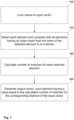
- Fig. 1 shows an example flow diagram of a method of calculating the prior instances of a vector.
- the values are loaded to a vector of a vector processing system, hereafter called input vector.
- each element of the input vector is selected and compared with all elements of the input vector having an index lower than the index of the selected element to identify matches.
- the number of matches for each selected element is calculated. The number of matches is the number of elements having an index lower than the index of the selected element that have the same value as the selected element.
- a first output vector is generated. The first output vector has the same number of elements as the input vector and the same indexes.
- each element of the input vector corresponds to the element of the first output vector having the same index.
- Each element of the first output vector has a value equal to the number of matches calculated for the corresponding element of the input vector. In one implementation, this may be done by incrementing by one the value of the element of the first output vector corresponding to the selected element when a comparison identifies a match. In this implementation, the values of the elements of the first output vector must be equal to zero or set equal to zero before they are processed.
- Fig. 1a shows an illustrative example of the VPI instruction semantics.
- the elements are processed from left to right.
- the value 5 is encountered for the first time in the position with index 1 of the input vector (in). Up to this point all elements of the output vector (out) are equal to 0.
- the value 5 is encountered again for the second time in the position with index 2.
- the position with index 2 of the output vector (out) is set to 1, which corresponds to the number of prior instances of the value of the element in the position with index 2.
- the position with index 3 of the output vector (out) is set to 2, which corresponds to the number of prior instances of the value of the element in the position with index 3.
- Fig. 2 shows an example flow diagram of a method of calculating the last unique instances of a vector.
- first step 210 m values are loaded to a vector, hereafter called input vector.
- a vector of the same number of elements as the input vector, hereafter known as second output vector, is generated having the same indexes.
- Each element of the input vector corresponds to the element of the second output vector having the same index.
- step 210 e is set equal to 0.
- Fig. 2a shows an illustrative example of the VLU instruction semantics.
- the output vector (out) may be considered a vector mask where each element is a bit.
- the first value may be 1 and the second value may be 0.
- a bit in the output vector is set only if the corresponding value in the input vector is not seen afterwards. These cases are shaded in the input vector.
- the elements of the output vector with indexes 0, 3, 6 and 7 are set to 1, as they correspond to the last unique instance of the values of the elements of the input vector.
- Fig. 3 shows an example flow diagram of a method of calculating the prior instances of a vector using a Content Addressable Memory (CAM).
- the CAM may have a number of entries equal to the number of elements (m) of the input vector. Each entry may comprise at least a key field, a count field and a valid field. An entry is considered valid when its valid field is set equal to a third value, e.g. equal to Y, and not valid when set equal to a fourth value, e.g. when equal to N.
- the valid field of all entries is set to N. Also e is set equal to 0. Then, the e-th element of the input vector is selected.
- step 310 the value of the selected element is compared with the key field of all valid entries.
- step 315 it is checked if a matching entry is identified, i.e. an entry having a key field equal to the value of the selected (e-th) element. If the answer is yes, then in step 325, the value of the element of the first output vector corresponding to the selected element (e-th) is set equal to the count field of the matching entry. If not, then, in step 320, a new valid entry is generated. Following step 325, the count field of the matching entry is incremented by one in step 335. Then the process continues in step 355.
- Each entry may further comprise a last index field.
- the last index field may be updated in step 370, either after step 335 when a matching entry is identified or after step 320, when a new valid entry is generated.
- the updated last index field is then set equal to the index of the selected element.
- Fig. 3a shows an example flow diagram of a method of calculating the last unique instances of an input vector using a Content Addressable Memory (CAM) after VPI has been calculated.
- step 375 it is checked if the last index field for all elements has been updated, i.e. if VPI is completed. If not, then the process waits until this condition is met. After updating the last index field for all elements then the process continues in step 380.
- step 380 the elements of the second output vector are set equal to the second value.
- each element of the second output vector having an index equal to the value of the last index field of a valid entry is set equal to the first value.
- VLU is considered completed.
- Fig. 4 shows an example implementation to calculate VPI using a CAM memory.
- the diagram shows the state of the process at an intermediate step before the instruction has completed.
- Six of the eight elements of the input vector have already been processed and six of the eight elements of the output vector have been calculated (shown with a dotted pattern).
- the seventh element of the input vector is being processed and the corresponding element of the output vector is just about to be calculated.
- the CAM memory shown in Fig. 4 comprises eight entries. Each entry comprises a valid, a key, a last index (last idx in the figure) and a count field.
- four valid fields are set to Y and the rest are set to N.
- the value 9 of the element with index 6 of the input is now used to access the CAM. As the value 9 has already been encountered in a previously processed element (element with index 5) there is already a valid entry with a key field equal to the value of the element of the input vector with index 6.
- the value located in the count field of the valid entry is copied into the seventh element of the first output vector. This value is equal to 1 because there has been exactly one element of input encountered up until this point with the value 9. Afterwards the count field is incremented by 1 and the value of the corresponding last idx field is updated to 6 as this refers to the most recent index of the input vector where the value 9 has been observed.
- the last idx field is not used to calculate VPI however it is relatively simple to update this field when updating count, this way if VLU is executed after VPI using the same input, all that remains to be done is to convert the array of last idx values to a bitmask. This can be done in relatively few cycles.
- a way to optimize the above process is to select and process in parallel a plurality of elements of the input vector using multiple lanes, as defined in Asanovic, 1998, p. 32, section 3.3.
- One obvious obstacle to extend this implementation to multiple lanes is that the methods for calculating prior instances and last unique elements are defined serially.
- Adjacent elements of the input vector may be arranged into groups. The elements within a group may be processed in parallel provided they do not conflict with one another otherwise they are processed serially. Detecting conflicts requires comparators where l is the number of parallel lanes targeted, i.e. the group size.
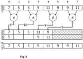
- Fig. 5 illustrates a parallel optimization using two parallel paths (or lanes ) .
- Each block of the timelines represents the time that is required to process one element, however the parallel timeline shows stacked blocks meaning the elements of this group are processed in tandem.
- the first, third and fourth groups of elements can be processed in parallel as there are no conflicts.
- the second group of elements has a conflict and needs to be serialized.
- the hatched box represents the relative time saved over the serial implementation.
- Fig. 6 shows an example flow diagram of a method of updating a histogram array with the values of the input vector.
- a first output vector may be generated from the input vector using the VPI instruction as described with reference to Fig. 1 or 3 .
- a second output vector may be generated from the input vector using the VLU instruction as described with reference to Fig. 2 or 3a .
- the first output vector is compressed into a third output vector by using the second output vector as mask. The elements of the first output vector corresponding to elements of the second output vector having the first value are selected by the compress instruction.
- a fourth output vector is generated by adding one to the values of the elements of the third output vector.
- step 625 the input vector is compressed into a fifth output vector by using the second output vector as mask.
- step 630 the values of the elements of the fifth output vector are used as indexes to gather from the histogram array to a sixth output vector.
- a seventh output vector is generated by adding the values of the elements of the sixth output vector and of the fourth output vector.
- step 640 the values of the elements of the fifth output vector are used as indexes to scatter the values of the elements of the seventh output vector to the histogram array.
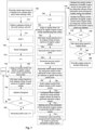
- Fig. 7 shows an example flow diagram of a method of sorting an input array.
- first step 705 an initial input array having at most n x m values organized in at least n consecutive blocks of at most m consecutive values, each value having z number of bits is provided.
- step 710 a plurality j of subsets of bits of the values is defined.
- step 735 the value of each element of the input vector is set equal to the k-th subset of bits of the value of the element in the eighth output vector having the same index.
- the histogram array may be updated with the input vector according to the method described with reference to Fig. 6 .
- steps 764, 765 the VPI and VLU instructions are used to generate the first and second output vectors.
- the VPI, VLU instructions may be implemented according to examples disclosed herein with reference to Fig. 1 , 2 , 3 and 3a .
- a ninth output vector is generated by using the values of the elements of the input vector as indexes to gather from the prefix sum.
- a tenth output vector is generated by adding the values of the elements of the first output vector to those of the ninth output vector.
- the tenth output vector is compressed into an eleventh output vector by using the second output vector as mask.
- one is added to the values of the elements of the eleventh output vector to generate a twelfth output vector.
- step 774 the input vector is compressed into a thirteenth output vector by using the second output vector as mask.
- step 776 the values of the elements of the thirteenth output vector are used as indexes to scatter the values of the elements of the twelfth output vector to the prefix sum.
- step 778 the values of the elements of the tenth output vector are used as indexes to scatter the values of the elements of the eighth output vector to the output array.
- steps 805 and 810 the input is loaded iteratively and a histogram array is created for the first subset of the input's bits.
- step 805 the input is loaded into a vector (v) and the first subset of bits of these values are selected.
- Step 805 corresponds to steps 730 and 735 of Fig. 7 .
- the vector of selected bits is used to update a histogram array.
- Step 810 corresponds to step 740 of Fig. 7 . Steps 805 and 810 are repeated for the rest of the blocks of the input array (not shown).
- step 815 a prefix sum is performed over the histogram array.
- Step 815 corresponds to step 750 of Fig. 7 .
- steps 820, 825 and 830 the entire input array is loaded again and scattered to an output array with indexes determined by the prefix sum.
- step 820 the input is reloaded into a vector in an identical way to step 805 and the same subset of bits is selected.
- step 820 corresponds to steps 760 and 762 of Fig. 7 .
- step 825 the selected bits are indexes into the prefix sum which is read and incremented.
- the prefix sum is updated.
- Step 830 The values loaded from the prefix sum are modified according to the calculated prior instances and are stored in a vector (offset) used in the next step 830.
- Step 825 corresponds to steps 764 to 776.
- step 830 the values of the elements of the offset are used as indexes to scatter the values of the elements of vector v to the output array.
- Step 830 corresponds to step 778 of Fig. 7 . Steps 820, 825 and 830 are repeated for the rest of the blocks of the input array (not shown).
Landscapes
- Engineering & Computer Science (AREA)
- Theoretical Computer Science (AREA)
- Software Systems (AREA)
- Physics & Mathematics (AREA)
- General Engineering & Computer Science (AREA)
- General Physics & Mathematics (AREA)
- Mathematical Physics (AREA)
- Computer Hardware Design (AREA)
- Complex Calculations (AREA)
- Management, Administration, Business Operations System, And Electronic Commerce (AREA)
- Advance Control (AREA)
Claims (13)
- Procédé mettant en oeuvre un algorithme de tri radix vectorisé dans un système de traitement vectoriel pour traiter une pluralité de valeurs appartenant à un ensemble de données, le système de traitement vectoriel comprenant au moins un vecteur d'entrée ayant un certain nombre d'éléments avec un index unique attribué à chaque élément, les index étant attribués dans un ordre ascendant, l'ordre ascendant correspondant à la position des éléments dans le vecteur d'entrée, le procédé utilisant une instruction SIMD (single instruction multiple data) pour découvrir des instances multiples de valeurs récurrentes dans le vecteur d'entrée et comprenant :le chargement (110) des valeurs dans le vecteur d'entrée ;la sélection (115) de chaque élément du vecteur d'entrée ;la comparaison (115) de chaque élément sélectionné avec tous les éléments du vecteur d'entrée ayant un indice inférieur à l'indice de l'élément sélectionné, pour calculer (120) le nombre de correspondances pour l'élément sélectionné, dans lequel le nombre de correspondances est le nombre d'éléments ayant la même valeur que l'élément sélectionné ; etgénérer (125) un premier vecteur de sortie du même nombre d'éléments que le vecteur d'entrée et des mêmes index, dans lequel chaque élément du vecteur d'entrée correspond à l'élément du premier vecteur de sortie ayant le même index, dans lequel chaque élément du premier vecteur de sortie a une valeur égale au nombre de correspondances calculé pour l'élément correspondant du vecteur d'entrée ; dans lequel le procédé utilise une mémoire adressable par le contenu (CAM) ayant un nombre d'entrées égal au nombre d'éléments du vecteur d'entrée, chaque entrée comprenant au moins un champ de clé, un champ de comptage et un champ valide, dans lequel une entrée est valide lorsque le champ valide de l'entrée est fixé à une troisième valeur et non valide lorsque le champ valide de l'entrée est fixé à une quatrième valeur, le champ valide de toutes les entrées étant initialement fixé (305) à la quatrième valeur ; dans lequella sélection (310) de chaque élément du vecteur d'entrée est effectuée dans un ordre ascendant d'index, dans lequel la comparaison de chaque élément sélectionné avec tous les éléments du vecteur d'entrée ayant un index inférieur à l'index de l'élément sélectionné comprend :la comparaison (315) de la valeur de l'élément sélectionné avec le champ clé de toutes les entrées valides pour soit identifier une entrée correspondante ayant un champ clé égal à la valeur de l'élément sélectionné, soit générer une nouvelle entrée valide sinon,dans lequel la génération du premier vecteur de sortie est effectuée par les étapes suivantes :
lorsqu'une entrée correspondante est identifiée, alors :la valeur de l'élément du premier vecteur de sortie correspondant à l'élément sélectionné est rendue égale au champ de comptage de l'entrée correspondante (325), puisle champ de comptage de l'entrée correspondante est incrémenté d'un (335) ;lorsque aucune correspondance n'est trouvée, une nouvelle entrée valide est générée (320) en sélectionnant une entrée non valide et en fixant le champ valide de l'entrée sélectionnée à la troisième valeur, puisle champ clé de l'entrée sélectionnée est défini comme étant égal à la valeur de l'élément sélectionné (330) ;la valeur de l'élément du premier vecteur de sortie correspondant à l'élément sélectionné est fixée à zéro (340) ; et ensuitele champ de comptage de l'entrée sélectionnée est fixé à un (350). - Procédé selon la revendication 1, comprenant en outre :la génération (220 - 250) d'un second vecteur de sortie du même nombre d'éléments que le vecteur d'entrée et avec les mêmes index, dans lequel chaque élément du vecteur d'entrée correspond à l'élément du second vecteur de sortie ayant le même index ; etdans lequel la valeur de chaque élément du second vecteur de sortie est fixée égale à une première valeur (235) à moins que l'élément correspondant du vecteur d'entrée ait une valeur égale à la valeur d'un élément du vecteur d'entrée avec un indice supérieur à l'indice de l'élément correspondant, de sorte que la valeur dudit élément du second vecteur de sortie est fixée égale à une seconde valeur.
- Procédé selon la revendication 2, dans lequel le second vecteur de sortie est un masque vectoriel.
- Procédé selon l'une quelconque des revendications 1 à 3, dans lequel chaque entrée comprend en outre un champ de dernier indice, dans lequel soit le champ de dernier indice d'une entrée correspondante est mis à jour (370) lorsqu'une entrée correspondante est identifiée, soit le champ de dernier indice d'une nouvelle entrée valide est mis à jour lorsque la nouvelle entrée valide est générée, et
dans lequel le dernier champ d'index mis à jour est égal à l'index de l'élément sélectionné. - Procédé selon la revendication 4, dans lequel, après avoir mis à jour le dernier champ d'indice pour tous les éléments (375), le procédé comprend en outre la génération du second vecteur de sortie, et
dans lequel la valeur de chaque élément du second vecteur de sortie ayant un index égal au dernier champ d'index d'une entrée valide est fixée égale à la première valeur (385) et sinon la valeur de chaque élément du second vecteur de sortie est fixée égale à la seconde valeur (380). - Procédé selon l'une quelconque des revendications 1 à 5, dans lequel une pluralité d'éléments du vecteur d'entrée sont sélectionnés et traités en parallèle.
- Le procédé selon la revendication 6, comprenant en outre :la sélection simultanée d'une pluralité d'éléments du vecteur d'entrée ;comparer les valeurs sélectionnées simultanément les unes aux autres ; ettraiter en parallèle la pluralité de valeurs si ladite comparaison n'identifie aucune correspondance.
- Procédé selon l'une quelconque des revendications 2 à 7 lorsqu'il dépend de la revendication 2, comprenant en outre :
l'utilisation (615) du deuxième vecteur de sortie comme masque sur le premier vecteur de sortie pour sélectionner des éléments du premier vecteur de sortie et générer un troisième vecteur de sortie. - Procédé selon la revendication 8, dans lequel la génération du troisième vecteur de sortie comprend :l'identification des éléments du deuxième vecteur de sortie ayant la première valeur ; etla compression (615) du premier vecteur de sortie en le troisième vecteur de sortie en utilisant les éléments du deuxième vecteur de sortie ayant la première valeur comme masque.
- Procédé selon la revendication 9, comprenant en outre l'utilisation du troisième vecteur de sortie pour incrémenter un tableau d'histogrammes par :ajoutant (620) un aux valeurs des éléments du troisième vecteur de sortie pour générer un quatrième vecteur de sortie ;la compression (625) du vecteur d'entrée en un cinquième vecteur de sortie en utilisant le deuxième vecteur de sortie comme masque ;utiliser (630) les valeurs des éléments du cinquième vecteur de sortie comme index pour rassembler à partir du tableau d'histogrammes à un sixième vecteur de sortie ;générer (635) un septième vecteur de sortie, en ajoutant les valeurs des éléments du sixième vecteur de sortie et du quatrième vecteur de sortie ; etutiliser (640) les valeurs des éléments du cinquième vecteur de sortie en tant qu'indices pour disperser les valeurs des éléments du septième vecteur de sortie dans le tableau d'histogrammes.
- Procédé selon la revendication 10, comprenant en outre :la fourniture (705) d'un tableau d'entrée initial ayant au plus n x m valeurs organisées en au moins n blocs consécutifs d'au plus m valeurs consécutives, chaque valeur ayant un nombre z de bits,définir (710) une pluralité j de sous-ensembles de bits des valeurs, où zk est le nombre de bits du sous-ensemble k, k=1 à j, où z1+z2+...+zj=z et où tous les bits d'un sous-ensemble k-1, k=2 à j, sont moins significatifs que tous les bits d'un sous-ensemble k ;répéter pour chaque sous-ensemble de bits k, k=1 à j, en commençant par k=1 et dans un ordre consécutif :∘ réinitialiser (720) le tableau d'histogramme en mettant à zéro toutes les valeurs du tableau d'histogramme ;∘ répéter pour chaque bloc i, i=1 à n, en commençant par i=1 et dans un ordre consécutif :▪ fixer (730) les valeurs d'un huitième vecteur de sortie égal aux valeurs du bloc tout en maintenant dans le huitième vecteur de sortie l'ordre consécutif que lesdites valeurs avaient dans le tableau d'entrée ;▪ fixant (735) la valeur de chaque élément du vecteur d'entrée égale au sous-ensemble k de bits de la valeur de l'élément dans le huitième vecteur de sortie ayant le même indice ;▪ mise à jour (740) du tableau d'histogrammes selon les étapes réalisées dans la revendication 11 ;∘ génération (750) d'une somme de préfixe du réseau d'histogrammes, dans laquelle la valeur du premier élément de la somme de préfixe est fixée à zéro et la valeur de chacun des autres éléments de la somme de préfixe est égale à la somme de la valeur de l'élément ayant l'indice précédent dans la somme de préfixe plus la valeur de l'élément du réseau d'histogrammes ayant le même indice précédent ;∘ en répétant pour chaque bloc i, i=1 à n, en partant de i=1 et dans un ordre consécutif :▪ fixant (760) les valeurs d'un huitième vecteur de sortie égales aux valeurs du bloc tout en maintenant dans le huitième vecteur de sortie l'ordre consécutif que lesdites valeurs avaient dans le tableau d'entrée.▪ fixant (762) la valeur de chaque élément du vecteur d'entrée égale au sous-ensemble k de bits de la valeur de l'élément dans le huitième vecteur de sortie ayant le même indice ;▪ générer (764, 765) le premier vecteur de sortie selon la revendication 1 et le deuxième vecteur de sortie selon la revendication 2 ;▪ générer (766) un neuvième vecteur de sortie en utilisant les valeurs des éléments du vecteur d'entrée comme indices à rassembler à partir de la somme préfixe ;▪ générer (768) un dixième vecteur de sortie en ajoutant les valeurs des éléments du premier vecteur de sortie et du neuvième vecteur de sortie ;▪ compresser (770) le dixième vecteur de sortie en un onzième vecteur de sortie en utilisant le deuxième vecteur de sortie comme masque ;▪ ajouter (772) un aux valeurs des éléments du onzième vecteur de sortie pour générer un douzième vecteur de sortie ;▪ compresser (774) le vecteur d'entrée en un treizième vecteur en utilisant le deuxième vecteur de sortie comme masque ;▪ utiliser (776) les valeurs des éléments du treizième vecteur comme indices pour disperser les valeurs des éléments du douzième vecteur de sortie à la somme de préfixe ;▪ utiliser (778) les valeurs des éléments du dixième vecteur de sortie comme indices pour disperser les valeurs des éléments du huitième vecteur de sortie vers le tableau de sortie ;∘ fixer (782) le tableau d'entrée égal au tableau de sortie ; etFournir (786) le tableau de sortie comme le tableau d'entrée initial trié.
- Dispositif informatique comprenant une mémoire et un processeur, dans lequel la mémoire stocke des instructions de programme informatique exécutables par le processeur, lesdites instructions étant adaptées pour exécuter un procédé selon l'une quelconque des revendications 1 à 11, lorsqu'elles sont exécutées sur le dispositif informatique.
- Produit de programme informatique comprenant des instructions adaptées pour exécuter un procédé selon l'une quelconque des revendications 1 à 11, lorsqu'il est exécuté sur un dispositif informatique.
Applications Claiming Priority (1)
| Application Number | Priority Date | Filing Date | Title |
|---|---|---|---|
| PCT/EP2015/052394 WO2016124242A1 (fr) | 2015-02-05 | 2015-02-05 | Procédé et dispositifs pour découvrir de multiples instances de valeurs récurrentes dans un vecteur avec une application à un tri |
Publications (3)
| Publication Number | Publication Date |
|---|---|
| EP3254184A1 EP3254184A1 (fr) | 2017-12-13 |
| EP3254184B1 true EP3254184B1 (fr) | 2023-06-07 |
| EP3254184C0 EP3254184C0 (fr) | 2023-06-07 |
Family
ID=52462922
Family Applications (1)
| Application Number | Title | Priority Date | Filing Date |
|---|---|---|---|
| EP15703274.9A Active EP3254184B1 (fr) | 2015-02-05 | 2015-02-05 | Procédé pour découvrir de multiples instances de valeurs récurrentes dans un vecteur ainsi que dispositif et programme d'ordinateur correspondants |
Country Status (6)
| Country | Link |
|---|---|
| US (1) | US10282203B2 (fr) |
| EP (1) | EP3254184B1 (fr) |
| JP (1) | JP6615209B2 (fr) |
| CN (1) | CN107430506B (fr) |
| ES (1) | ES2950383T3 (fr) |
| WO (1) | WO2016124242A1 (fr) |
Families Citing this family (3)
| Publication number | Priority date | Publication date | Assignee | Title |
|---|---|---|---|---|
| EP4557209A3 (fr) | 2015-06-10 | 2025-08-13 | Mobileye Vision Technologies Ltd. | Processeur d'images et procédés de traitement d'une image |
| US10592466B2 (en) * | 2016-05-12 | 2020-03-17 | Wisconsin Alumni Research Foundation | Graphic processor unit providing reduced storage costs for similar operands |
| US11436010B2 (en) | 2017-06-30 | 2022-09-06 | Intel Corporation | Method and apparatus for vectorizing indirect update loops |
Family Cites Families (5)
| Publication number | Priority date | Publication date | Assignee | Title |
|---|---|---|---|---|
| JPH03154920A (ja) * | 1989-11-13 | 1991-07-02 | Hitachi Ltd | 高速ソート処理方式 |
| US20110010509A1 (en) * | 2009-07-07 | 2011-01-13 | L3 Communications Integrated Systems,L.P. | System and method of sorting and calculating statistics on large data sets with a known value range |
| US9639325B2 (en) * | 2012-03-01 | 2017-05-02 | International Business Machines Corporation | Finding a best matching string among a set of strings |
| US9715383B2 (en) * | 2012-03-15 | 2017-07-25 | International Business Machines Corporation | Vector find element equal instruction |
| WO2015152757A1 (fr) * | 2014-04-01 | 2015-10-08 | Huawei Technologies Co., Ltd | Procédés et appareil de dissimulation de données dans des unités de codage multicouche structurées |
-
2015
- 2015-02-05 EP EP15703274.9A patent/EP3254184B1/fr active Active
- 2015-02-05 CN CN201580074330.8A patent/CN107430506B/zh active Active
- 2015-02-05 ES ES15703274T patent/ES2950383T3/es active Active
- 2015-02-05 JP JP2017539601A patent/JP6615209B2/ja active Active
- 2015-02-05 US US15/548,083 patent/US10282203B2/en active Active
- 2015-02-05 WO PCT/EP2015/052394 patent/WO2016124242A1/fr not_active Ceased
Also Published As
| Publication number | Publication date |
|---|---|
| CN107430506A (zh) | 2017-12-01 |
| JP2018510401A (ja) | 2018-04-12 |
| US20180018173A1 (en) | 2018-01-18 |
| WO2016124242A1 (fr) | 2016-08-11 |
| WO2016124242A8 (fr) | 2017-02-23 |
| EP3254184C0 (fr) | 2023-06-07 |
| JP6615209B2 (ja) | 2019-12-04 |
| EP3254184A1 (fr) | 2017-12-13 |
| US10282203B2 (en) | 2019-05-07 |
| CN107430506B (zh) | 2020-11-06 |
| ES2950383T3 (es) | 2023-10-09 |
Similar Documents
| Publication | Publication Date | Title |
|---|---|---|
| Cracco et al. | Extremely fast construction and querying of compacted and colored de Bruijn graphs with GGCAT | |
| US20240004655A1 (en) | Computing Machine Using a Matrix Space And Matrix Pointer Registers For Matrix and Array Processing | |
| JP6605573B2 (ja) | 並列ディシジョン・ツリー・プロセッサー・アーキテクチャ | |
| US9886377B2 (en) | Pipelined convolutional operations for processing clusters | |
| KR102594768B1 (ko) | 데이터 처리장치의 데이터 항목들 내의 성분들의 계수 | |
| JP2009116854A (ja) | スキャン演算を遂行するシステム、方法、及びコンピュータ・プログラムプロダクト | |
| US11573793B2 (en) | Lazy push strategies for vectorized D-Heaps | |
| US20100318773A1 (en) | Inclusive "or" bit matrix compare resolution of vector update conflict masks | |
| JP2019517060A (ja) | ベクトル演算を実行する際にアドレス衝突を管理するための装置及び方法 | |
| EP3254184B1 (fr) | Procédé pour découvrir de multiples instances de valeurs récurrentes dans un vecteur ainsi que dispositif et programme d'ordinateur correspondants | |
| Goswami et al. | Gpu-accelerated large-scale genome assembly | |
| Houtgast et al. | An efficient gpuaccelerated implementation of genomic short read mapping with bwamem | |
| US12530170B2 (en) | Vector operation acceleration with convolution computation unit | |
| Jiang et al. | BQSim: GPU-accelerated Batch Quantum Circuit Simulation using Decision Diagram | |
| Vidal et al. | A multi-GPU implementation of a cellular genetic algorithm | |
| US20200159811A1 (en) | Assigning dependent matrix-vector multiplication operations to consecutive crossbars of a dot product engine | |
| US12135953B2 (en) | Systems, methods, and devices for the sorting of digital lists | |
| Raghunandan et al. | A parallel implementation of FastBit radix sort using MPI and CUDA | |
| Lee et al. | Accelerated block-sparsity-aware matrix reordering for leveraging tensor cores in sparse matrix-multivector multiplication | |
| Aji et al. | GPU-RMAP: accelerating short-read mapping on graphics processors | |
| Soroushnia et al. | High performance pattern matching on heterogeneous platform | |
| Abbas et al. | Parallelizing exact motif finding algorithms on multi-core | |
| Munekawa et al. | Accelerating Smith-Waterman algorithm for biological database search on CUDA-compatible GPUs | |
| Ordóñez-Guillén et al. | Heuristic search space generation for maximum clique problem inspired in biomolecular filtering | |
| Kaski et al. | Engineering motif search for large motifs |
Legal Events
| Date | Code | Title | Description |
|---|---|---|---|
| STAA | Information on the status of an ep patent application or granted ep patent |
Free format text: STATUS: THE INTERNATIONAL PUBLICATION HAS BEEN MADE |
|
| PUAI | Public reference made under article 153(3) epc to a published international application that has entered the european phase |
Free format text: ORIGINAL CODE: 0009012 |
|
| STAA | Information on the status of an ep patent application or granted ep patent |
Free format text: STATUS: REQUEST FOR EXAMINATION WAS MADE |
|
| 17P | Request for examination filed |
Effective date: 20170905 |
|
| AK | Designated contracting states |
Kind code of ref document: A1 Designated state(s): AL AT BE BG CH CY CZ DE DK EE ES FI FR GB GR HR HU IE IS IT LI LT LU LV MC MK MT NL NO PL PT RO RS SE SI SK SM TR |
|
| AX | Request for extension of the european patent |
Extension state: BA ME |
|
| DAX | Request for extension of the european patent (deleted) | ||
| STAA | Information on the status of an ep patent application or granted ep patent |
Free format text: STATUS: EXAMINATION IS IN PROGRESS |
|
| 17Q | First examination report despatched |
Effective date: 20190912 |
|
| GRAP | Despatch of communication of intention to grant a patent |
Free format text: ORIGINAL CODE: EPIDOSNIGR1 |
|
| RIC1 | Information provided on ipc code assigned before grant |
Ipc: G06F 9/38 20060101ALI20220413BHEP Ipc: G06F 9/30 20060101ALI20220413BHEP Ipc: G06F 7/24 20060101AFI20220413BHEP |
|
| STAA | Information on the status of an ep patent application or granted ep patent |
Free format text: STATUS: GRANT OF PATENT IS INTENDED |
|
| INTG | Intention to grant announced |
Effective date: 20220519 |
|
| GRAJ | Information related to disapproval of communication of intention to grant by the applicant or resumption of examination proceedings by the epo deleted |
Free format text: ORIGINAL CODE: EPIDOSDIGR1 |
|
| STAA | Information on the status of an ep patent application or granted ep patent |
Free format text: STATUS: EXAMINATION IS IN PROGRESS |
|
| INTC | Intention to grant announced (deleted) | ||
| GRAP | Despatch of communication of intention to grant a patent |
Free format text: ORIGINAL CODE: EPIDOSNIGR1 |
|
| STAA | Information on the status of an ep patent application or granted ep patent |
Free format text: STATUS: GRANT OF PATENT IS INTENDED |
|
| INTG | Intention to grant announced |
Effective date: 20220907 |
|
| GRAS | Grant fee paid |
Free format text: ORIGINAL CODE: EPIDOSNIGR3 |
|
| GRAA | (expected) grant |
Free format text: ORIGINAL CODE: 0009210 |
|
| STAA | Information on the status of an ep patent application or granted ep patent |
Free format text: STATUS: THE PATENT HAS BEEN GRANTED |
|
| AK | Designated contracting states |
Kind code of ref document: B1 Designated state(s): AL AT BE BG CH CY CZ DE DK EE ES FI FR GB GR HR HU IE IS IT LI LT LU LV MC MK MT NL NO PL PT RO RS SE SI SK SM TR |
|
| REG | Reference to a national code |
Ref country code: GB Ref legal event code: FG4D |
|
| REG | Reference to a national code |
Ref country code: CH Ref legal event code: EP Ref country code: AT Ref legal event code: REF Ref document number: 1577068 Country of ref document: AT Kind code of ref document: T Effective date: 20230615 |
|
| REG | Reference to a national code |
Ref country code: DE Ref legal event code: R096 Ref document number: 602015083828 Country of ref document: DE |
|
| U01 | Request for unitary effect filed |
Effective date: 20230630 |
|
| U07 | Unitary effect registered |
Designated state(s): AT BE BG DE DK EE FI FR IT LT LU LV MT NL PT SE SI Effective date: 20230707 |
|
| REG | Reference to a national code |
Ref country code: LT Ref legal event code: MG9D |
|
| REG | Reference to a national code |
Ref country code: ES Ref legal event code: FG2A Ref document number: 2950383 Country of ref document: ES Kind code of ref document: T3 Effective date: 20231009 |
|
| PG25 | Lapsed in a contracting state [announced via postgrant information from national office to epo] |
Ref country code: NO Free format text: LAPSE BECAUSE OF FAILURE TO SUBMIT A TRANSLATION OF THE DESCRIPTION OR TO PAY THE FEE WITHIN THE PRESCRIBED TIME-LIMIT Effective date: 20230907 |
|
| PG25 | Lapsed in a contracting state [announced via postgrant information from national office to epo] |
Ref country code: RS Free format text: LAPSE BECAUSE OF FAILURE TO SUBMIT A TRANSLATION OF THE DESCRIPTION OR TO PAY THE FEE WITHIN THE PRESCRIBED TIME-LIMIT Effective date: 20230607 Ref country code: HR Free format text: LAPSE BECAUSE OF FAILURE TO SUBMIT A TRANSLATION OF THE DESCRIPTION OR TO PAY THE FEE WITHIN THE PRESCRIBED TIME-LIMIT Effective date: 20230607 Ref country code: GR Free format text: LAPSE BECAUSE OF FAILURE TO SUBMIT A TRANSLATION OF THE DESCRIPTION OR TO PAY THE FEE WITHIN THE PRESCRIBED TIME-LIMIT Effective date: 20230908 |
|
| PG25 | Lapsed in a contracting state [announced via postgrant information from national office to epo] |
Ref country code: SK Free format text: LAPSE BECAUSE OF FAILURE TO SUBMIT A TRANSLATION OF THE DESCRIPTION OR TO PAY THE FEE WITHIN THE PRESCRIBED TIME-LIMIT Effective date: 20230607 |
|
| PG25 | Lapsed in a contracting state [announced via postgrant information from national office to epo] |
Ref country code: IS Free format text: LAPSE BECAUSE OF FAILURE TO SUBMIT A TRANSLATION OF THE DESCRIPTION OR TO PAY THE FEE WITHIN THE PRESCRIBED TIME-LIMIT Effective date: 20231007 |
|
| PG25 | Lapsed in a contracting state [announced via postgrant information from national office to epo] |
Ref country code: SM Free format text: LAPSE BECAUSE OF FAILURE TO SUBMIT A TRANSLATION OF THE DESCRIPTION OR TO PAY THE FEE WITHIN THE PRESCRIBED TIME-LIMIT Effective date: 20230607 Ref country code: SK Free format text: LAPSE BECAUSE OF FAILURE TO SUBMIT A TRANSLATION OF THE DESCRIPTION OR TO PAY THE FEE WITHIN THE PRESCRIBED TIME-LIMIT Effective date: 20230607 Ref country code: RO Free format text: LAPSE BECAUSE OF FAILURE TO SUBMIT A TRANSLATION OF THE DESCRIPTION OR TO PAY THE FEE WITHIN THE PRESCRIBED TIME-LIMIT Effective date: 20230607 Ref country code: IS Free format text: LAPSE BECAUSE OF FAILURE TO SUBMIT A TRANSLATION OF THE DESCRIPTION OR TO PAY THE FEE WITHIN THE PRESCRIBED TIME-LIMIT Effective date: 20231007 Ref country code: CZ Free format text: LAPSE BECAUSE OF FAILURE TO SUBMIT A TRANSLATION OF THE DESCRIPTION OR TO PAY THE FEE WITHIN THE PRESCRIBED TIME-LIMIT Effective date: 20230607 |
|
| PG25 | Lapsed in a contracting state [announced via postgrant information from national office to epo] |
Ref country code: PL Free format text: LAPSE BECAUSE OF FAILURE TO SUBMIT A TRANSLATION OF THE DESCRIPTION OR TO PAY THE FEE WITHIN THE PRESCRIBED TIME-LIMIT Effective date: 20230607 |
|
| U20 | Renewal fee for the european patent with unitary effect paid |
Year of fee payment: 10 Effective date: 20240129 |
|
| REG | Reference to a national code |
Ref country code: DE Ref legal event code: R097 Ref document number: 602015083828 Country of ref document: DE |
|
| PLBE | No opposition filed within time limit |
Free format text: ORIGINAL CODE: 0009261 |
|
| STAA | Information on the status of an ep patent application or granted ep patent |
Free format text: STATUS: NO OPPOSITION FILED WITHIN TIME LIMIT |
|
| 26N | No opposition filed |
Effective date: 20240308 |
|
| PG25 | Lapsed in a contracting state [announced via postgrant information from national office to epo] |
Ref country code: MC Free format text: LAPSE BECAUSE OF FAILURE TO SUBMIT A TRANSLATION OF THE DESCRIPTION OR TO PAY THE FEE WITHIN THE PRESCRIBED TIME-LIMIT Effective date: 20230607 |
|
| REG | Reference to a national code |
Ref country code: CH Ref legal event code: PL |
|
| PG25 | Lapsed in a contracting state [announced via postgrant information from national office to epo] |
Ref country code: CH Free format text: LAPSE BECAUSE OF NON-PAYMENT OF DUE FEES Effective date: 20240229 |
|
| PG25 | Lapsed in a contracting state [announced via postgrant information from national office to epo] |
Ref country code: CH Free format text: LAPSE BECAUSE OF NON-PAYMENT OF DUE FEES Effective date: 20240229 |
|
| U1N | Appointed representative for the unitary patent procedure changed after the registration of the unitary effect |
Representative=s name: TRBL INTELLECTUAL PROPERTY; ES |
|
| PG25 | Lapsed in a contracting state [announced via postgrant information from national office to epo] |
Ref country code: IE Free format text: LAPSE BECAUSE OF NON-PAYMENT OF DUE FEES Effective date: 20240205 |
|
| PG25 | Lapsed in a contracting state [announced via postgrant information from national office to epo] |
Ref country code: IE Free format text: LAPSE BECAUSE OF NON-PAYMENT OF DUE FEES Effective date: 20240205 |
|
| U20 | Renewal fee for the european patent with unitary effect paid |
Year of fee payment: 11 Effective date: 20250205 |
|
| PG25 | Lapsed in a contracting state [announced via postgrant information from national office to epo] |
Ref country code: CY Free format text: LAPSE BECAUSE OF FAILURE TO SUBMIT A TRANSLATION OF THE DESCRIPTION OR TO PAY THE FEE WITHIN THE PRESCRIBED TIME-LIMIT; INVALID AB INITIO Effective date: 20150205 |
|
| PG25 | Lapsed in a contracting state [announced via postgrant information from national office to epo] |
Ref country code: HU Free format text: LAPSE BECAUSE OF FAILURE TO SUBMIT A TRANSLATION OF THE DESCRIPTION OR TO PAY THE FEE WITHIN THE PRESCRIBED TIME-LIMIT; INVALID AB INITIO Effective date: 20150205 |
|
| PG25 | Lapsed in a contracting state [announced via postgrant information from national office to epo] |
Ref country code: TR Free format text: LAPSE BECAUSE OF FAILURE TO SUBMIT A TRANSLATION OF THE DESCRIPTION OR TO PAY THE FEE WITHIN THE PRESCRIBED TIME-LIMIT Effective date: 20230607 |
|
| U20 | Renewal fee for the european patent with unitary effect paid |
Year of fee payment: 12 Effective date: 20260212 |
|
| PGFP | Annual fee paid to national office [announced via postgrant information from national office to epo] |
Ref country code: GB Payment date: 20260227 Year of fee payment: 12 |
|
| PGFP | Annual fee paid to national office [announced via postgrant information from national office to epo] |
Ref country code: ES Payment date: 20260304 Year of fee payment: 12 |